1
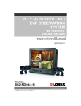
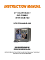
21” COLOR QUAD /
DVR COMBO
WITH 80GB HDD
SC21CD5444UQ-A80
FOR MORE INFORMATION
WWW.STRATEGICVISTA.COM
BEFORE OPERATING THIS SYSTEM, PLEASE READ THIS MANUAL THOROUGHLY
AND RETAIN IT FOR FUTURE REFERENCE
Thank you for purchasing the 21” Color Quad / DVR Combo from Strategic Vista. This
unique and innovative system provides a complete security package, with the
convenience of a built-in Digital Video Recorder combined with a 21” Color Quad
Observation System.
This system includes 3 CCD cameras, 1 Dome camera, and Web Ready Software to
connect the monitor to a PC
The DVR converts analog video into digital format and records them on a removable
hard disk drive (80 GB HDD included). Digital video allows you to quickly access and
search for a specific time segment or event which has been recorded. This system
features three different quality settings providing up to 2250 hours of recording
capability including 100 hours real time (using a 80 GB HDD).
To learn more about this 21” Color Quad / DVR Combo Observation system and to
learn about our complete range of accessory products, please visit our website at:
www.strategicvista.com
CAUTION
!
RISK OF ELECTRIC SHOCK. DO NOT OPEN.
CAUTION!
TO REDUCE THE RISK OF ELECTRIC SHOCK, DO NOT REMOVE
COVER (OR BACK). NO USER-SERVICEABLE PARTS INSIDE.
REFER SERVICING TO QUALIFIED SERVICE PERSONNEL.
Explanation of two Symbols
The lightning flash with arrowhead symbol, within an equilateral
triangle, is intended to alert the user to the presence of un-insulated
"dangerous voltage" within the product's enclosure that may be of
sufficient magnitude to constitute a risk of electric shock to persons.
!
The exclamation point within an equilateral triangle is intended to
alert the user to the presence of important operating and maintenance
(servicing) instructions in the literature accompanying the appliance.
THE GRAPHIC SYMBOLS WITH SUPPLEMENTAL MARKING ARE ON
THE BOTTOM OF THE SYSTEM.
“WARNING – TO PREVENT FIRE OR SHOCK HAZARD, DO NOT EXPOSE
THE UNIT TO RAIN OR MOISTURE”
-i-
NOTE
This equipment has been certified and found to comply with the limits regulated by
FCC, EMC and LVD. Therefore, it is designed to provide reasonable protection
against interference and will not cause interference with other appliance usage.
However, it is imperative that user follows this manual's guidelines to avoid improper
usage which may result in damage to the unit, electrical shock and fire hazard or
injury.
In order to improve the feature functions and quality of this product, the specifications
are subject to change without notice from time to time.
FCC CLASS B NOTICE
Note:
This equipment has been tested and found to comply with the limits For a Class B
digital device, pursuant to Part 15 of the FCC Rules. These limits are designed to
provide reasonable protection against harmful interference in a residential
installation. This equipment generates, uses and can radiate radio frequency energy
and, if not installed and used in accordance with the instruction, may cause harmful
interference to radio communications. However, there is no guarantee that
interference will not occur in a particular installation. If this equipment does cause
harmful interference to radio or television reception, (which can be determined by
turning the equipment off and on), the user is encouraged to try to correct the
interference by one or more of the following measures:
• Increase the separation between the camera and the monitor.
• Connect the equipment into an outlet on a circuit different from that to
which other electrical devices are connected.
• Consult the dealer or an experienced radio or television technician for help.
STRATEGIC VISTA CORP.
www.strategicvista.com
-ii-
CONTENTS:
GENERAL PRECAUTIONS -----------------------------------------------------------------------
1
FEATURES -------------------------------------------------------------------------------------------
2
SYSTEM CONTENTS -----------------------------------------------------------------------------
3
GETTING STARTED -------------------------------------------------------------------------------
4
CONTROLS - FRONT PANEL -------------------------------------------------------------------
5
MAIN MENU CONTROL---------------------------------------------------------------------------
8
SEARCH ----------------------------------------------------------------------------------------------- 13
PLAYBACK OPTIONS ----------------------------------------------------------------------------- 14
MASTER & SLAVE ---------------------------------------------------------------------------------- 14
PAN /TILT ZOOM -----------------------------------------------------------------------------------
15
CONTROLS - BACK PANEL --------------------------------------------------------------------- 16
REMOTE CONTROL-------------------------------------------------------------------------------
17
STANDARD WIRED CAMERA -----------------------------------------------------------------
18
DOME CAMERA-----------------------------------------------------------------------------------
19
CAMERA INSTALLATION -----------------------------------------------------------------------
20
TROUBLESHOOTING ----------------------------------------------------------------------------
21
TECHNICAL SPECIFICATIONS ---------------------------------------------------------------
22
OPTIONAL ACCESSORIES ---------------------------------------------------------------------
23
APPENDIX # 1 – INSTALLING THE HDD----------------------------------------------------
24
APPENDIX #2 – CONNECTION TO A SLAVE MONITOR & STANDARD VCR --
27
APPENDIX #3 – TYPICAL CONFIGURATION FOR A COMPLETE SYSTEM ----
28
APPENDIX #4 – RS 232 REMOTE PROTOCOL--------------------------------------------
29
APPENDIX #5 – RECORDING TIME ( IN HOURS ) --------------------------------------- 30
APPENDIX #6 - RECORDING TIME (GIGABYTES PER HOUR) ---------------------
31
CARE & MAINTENANCE--------------------------------------------------------------------------
32
GENERAL PRECAUTIONS:
1.
2.
3.
4.
5.
6.
7.
8.
9.
10.
11.
12.
13.
14.
Read Instructions
All of the safety and operating instructions should
be read and understood before the product is used.
Retain Instructions
The safety and operating instructions should be
retained for future reference.
Heed Warnings
All warnings on the product and the instruction
manual should be followed.
Follow Instructions
All operating and use instructions should be followed
for optimal performance
Cleaning
Disconnect this video product from the power supply
before cleaning. Do not use liquid cleaners or aerosol
cleaners. Use a damp cloth for cleaning.
Attachments
Do not use attachments not recommended by the
video product manufacturer as they may cause
hazards.
Water and Moisture
Do not use this product near water - for example,
near a bathtub, wash bowl, kitchen sink, wet
basement, or near a swimming pool.
Accessories
Use this product only with a stand, tripod, bracket or
table recommended by the manufacturer or sold
with the product. Any mounting of the product
should follow the manufacturer’s instructions.
Ventilation
This product should never be placed near or over a
radiator or heat register. This product should not be
placed in a built-in installation, such as a book case
or rack, unless proper ventilation is provided or the
Manufacturer’s instructions have been adhered to.
Power Source
This product should be operated from the type of
Power source indicated by the marking label. If you
are not sure of the type of power supply to your
location, consult your product dealer or your local
Power company
Power Cord Protection
Power supply cords should not be routed so that
they are likely to be walked on or pinched by items
placed on or near them
Lightning
For added protection, unplug this product from its
outlet during a lightning storm. This will prevent
damage to the video product due to lightning and
power surges
Overloading
To avoid the risk of fire and electric shock, do not
plug this product into an over-loaded power supply.
Object and Liquid Entry
Never push objects into the openings of this product
as they may touch dangerous voltage points that
may result in fire or electric shock. Never spill a
liquid of any kind on this product.
15.
16.
17.
18.
19.
20.
21.
22.
Servicing
Do not attempt to service this product yourself as
opening or removing covers may expose you to
voltage or other hazards. Refer all servicing to
qualified service personnel
Damage Requiring Service
Disconnect this product from the power supply
and refer servicing to qualified service
personnel under the following conditions:
a. When the power supply cord or plug is damaged
b. If objects have fallen into the product
c. If the product has been exposed to rain or liquids
d. If the product does not operate normally by
following the instruction manual. Adjust only
the controls that are covered in the instruction
manual as an improper adjustment may result
in damage and will often require extensive work
by a qualified service technician to restore
the product to its normal operation
e. If the product has been dropped or the cabinet
has been damaged
f. When the product displays a distinct change in
performance - this indicates a need for service
Replacement Parts
When replacement parts are required, be sure the
technician uses replacement parts specified by
the manufacturer. Unauthorized substitutions may
result in fire, electric shock, or other hazards.
Safety Check
Upon completion of any service to this product
ask the service technician to perform safety
checks to determine that the product is in
proper working condition.
Grounding or Polarization
This product is equipped with a three-wire
grounding-type plug, a plug having a third
(grounding) pin and will only fit into a
grounding-type power outlet. This is a safety
feature. If you are unable to insert the plug
into the outlet, contact your electrician to
replace your obsolete outlet. Do not defeat the
safety purpose of the grounding-type plug.
Power Lines
An outside antenna system should not be
located in the vicinity of overhead power lines
or other electric light or power circuits, or where
it can fall into such power lines or circuits.
When installing an outside antenna system,
extreme care should be taken to keep from
touching such power lines or circuits as contact
with them might be fatal.
Wall or Ceiling Mounting
The product should be mounted to a wall or ceiling
only as recommended by the manufacturer.
Heat
The product should be situated away from heat
such as radiators, heat registers, stoves, or other
products (including amplifiers) that produce heat.
-1-
CAUTIONS:
1. All the warnings and instructions of this manual should be followed
2. Remove the plug from the outlet before cleaning. Do not use liquid aerosol detergents. Use
water damped cloth for cleaning
3. Do not use this unit in very humid and wet places
4. Keep enough space around the unit for ventilation. Slots and openings of the cabinet should
not be blocked.
5. During flashes of lightning or cracks of thunder, or when the system is not used for a long time,
unplug the system power supply and disconnect the antenna and cables to protect the unit
from lightening or power surges.
Monitor Features:
• 21“ Color Quad with a high resolution of 450 TV lines
• Built-in Video Capture Card with Web Ready software for internet remote security monitoring
• View up to 4 camera locations in real time
• Pan/ Tilt capability on Channel 1 (Pelco D Protocol)
• Metal cabinet with 4 camera inputs (4 DIN / 4 BNC and 4 audio RCA)
• 2 way audio
• Single or Dual PIP / POP viewing options
• Selectable still frame in quad or full screen
• Dual Motion Sensing Alarm Function (using optional PIR motion sensor or Pixel-based Motion Detection)
• Remote control or main panel operation
• Multi-voltage system 100 – 240Volts, 50 / 60 Hz
Camera Features:
3 Color Cameras
• 1/4” CCD Color Camera
• Built in speaker and microphone to allow for two way audio communication
• Metal mounting bracket
1 Color Dome Camera
• 1/4” CCD Color Dome Camera
• 3.6 mm lens.
• 1.0 lux illumination
• One-way audio communication
DVR Features
•
•
•
•
•
•
•
•
•
•
100 Hour Real Time / 2250 Hour Recording (with 80 GB HDD, normal video quality)
High Quality Picture with Modified MJPEG Compression Format
3 Adjustable Video Quality Settings
Alarm, panic, repeat and timer options
Security password protection
Supports 20 ~300 GB HDD
Quick Multiple Search capability
Multiplexing feature allows you to playback each individual channel in Full Screen
Event list displays occurrences of Alarms, Video Loss, and Power Loss
RS232C communication port
-2-
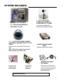
SYSTEM INCLUDES:
21” COLOR QUAD MONITOR
WITH BUILT-IN DVR
1 – ¼” CCD COLOR DOME CAMERA
WITH METAL BRACKET AND 57 FT OF
CABLE
(included with model SC21CD5444UQA80)
Note: This dome camera has a fixed
lens and does not Pan or Tilt
3 – 1/4” CCD COLOR
CAMERAS WITH METAL
STAND AND 57 FT CABLE
(3 cameras included with
Model SC21CD5444UQ-A80)
80 GB HARD DISK DRIVE
(HDD)
Already inserted into cabinet
INTERNET SECURITY
SOFTWARE
2 KEYS FOR
CARTRIDGE
OWNER’S
MANUAL
Please refer to the Quick Start
Guide and on-line manual for the
Digital Video Monitoring software,
and for more information on
Remote Monitoring
CHECK YOUR PACKAGE TO MAKE SURE THAT YOU RECEIVED THE COMPLETE SYSTEM, INCLUDING
THE COMPONENTS SHOWN ABOVE.
-3-
GETTING STARTED:
1.
2.
3.
Connect the AC Power Cord to the back of the monitor, and
connect up to 4 cameras to the 6 Pin DIN or BNC Video
inputs on the back of the monitor. Then turn the Main Power
Switch to ON.
Upon Powering Up, a message will appear “Please Check
HDD Key Lock before Turn ON”. This message is reminding
you to ensure that the cabinet of the DVR is locked before
proceeding.
*** MASTER HDD ***
HDD AUTO DETECT…….OK
HDD R/W CHECK………..OK
HDD SPACE ( xxxGB)…….OK
MODEL# XXXXXXXXXX
The check of the HDD key lock will be followed by an overall
diagnostic check of the HDD . The screen will appear as
shown to the right:
Note: The system is only checking for a MASTER HDD. If you have connected a SLAVE HDD to the
back of the monitor, refer to page 12 for instruction on how to enable your system to recognize it.
Note: If you get a “FAIL” message in HDD Auto Detect, the HDD is not installed correctly. Refer to
Appendix #1 if you encounter this problem as you will have to properly insert the HDD.
-4-
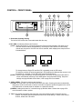
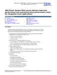
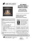
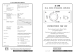
CONTROL - FRONT PANEL:
14
13
12
11
10
HDD
MIC
HDD
FULL
ALARM
CH1
CH2
SEQ
PIP
MENU
A-SEL
CH3
CH4
QUAD
PLAY
POWER/TIMER
REC
1
2
3
TALK
4
EVENT
SEARCH
5
REC
6
7
8
9
1. Removable Cartridge Casing
The built-in DVR comes with a removable hard disk drive tray.
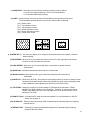
2. PIP / SEQ - this button performs two functions:
(1) PIP : Holding this button for 3 seconds triggers the Picture-In-Picture display. PIP allows you to
view two camera locations simultaneously, one being the main channel, the other being
viewed as a sub-picture. Dual PIP can also be selected, which displays two sub-pictures as
illustrated below.
SINGLE PIP
DUAL PIP
To change between Single PIP and Dual PIP, repeatedly press the PIP button.
To swap the positions of cameras appearing in PIP (between the Main and Sub screen), hold
this button for 3 seconds. To exit PIP mode, press the QUAD button.
(2) SEQ : Used to sequence between all camera locations in full screen in sequential order with the
screen automatically switching. Press SEQ again to stop sequential viewing. Sequence
settings are programmable via the Menu, refer to page 9 for more details.
3. A-SEL / MENU - This button performs two functions:
(1) A-SEL: In Quad mode, you can select the channel with audio. Pressing this button automatically
changes the audio from channel to channel. An audio microphone symbol will appear in the corner
of a Quad screen to indicate audio is available on a particular channel.
(2) MENU: Holding this button for 3 seconds brings up the Main Menu. Please refer to page 8 For
more information on Menu options.
4. TALK - By pressing and holding this button the user has the ability to talk to a specific camera
location. This button must be pressed the entire time, while talking. To listen to the camera
location, release the Talk button.
-5-
5. EVENT - Pressing this button brings up a list of up to 1000 Events, including Power Loss and Alarms. You
can scroll through Events using the and keys, and navigate between Pages of Events
using the and keys. Press Play / Enter to exit the Event list.
The following letters represent the different types of Events that you may find listed:
P : Shows the time when the POWER was turned ON
A : Shows the time when a PIR ALARM was triggered
M : Shows the time when Pixel-based MOTION detection was triggered
L : Shows when a Video LOSS from a Camera occurred
N : Starting time of storing data with Manual recording.
H : Time of problem occurring in HDD.
6. SEARCH - Pressing this button brings up the Search menu, which allows you to quickly find recordings.
For more information on Search options, please refer to page 13.
7. REC - Initiates manual recording.
8. PAUSE / STOP / FF / REW / PLAY
(1) PAUSE: This button serves 3 functions:
a) Press this button to pause video in playback.
b) Used to scroll Up in the Menu option screens..
c) Brings up the Pan/Tilt Zoom feature. For more information on Pan/Tilt Zoom, refer to page 15.
(2) STOP: This button serves 2 functions:
a) Press this button to stop in video playback.
b) Used to scroll Down in the Menu option screens.
(3) FF: This button serves 2 functions:
a) Begins high-speed forward playback during playback.
b) Used to scroll Right in the Menu option screens.
(4) REW: This button serves 2 functions:
a) Begins high-speed reverse playback during playback.
b) Used to scroll Left in the Menu option screens.
(5) PLAY: This button serves 2 functions:
a) Initiates video Playback. For more information on Playback, refer to page 14.
b) This button serves as the ENTER key in Menu mode.
9. REMOTE CONTROL SENSOR
10. POWER / KEY LOCK - This button serves two functions:
(1) POWER: Turns the monitor ON/OFF. A red LED indicator light turns ON when
the monitor is in Standby mode. Press the button to turn the power ON.
Note: The master power switch, which controls the monitor is located on the back of the unit.
Note: To provide longer life to the monitor, turn the Standby switch OFF when not in use.
The system will continue to record images even though no picture is showing.
(2) KEY LOCK: Holding this button for 3 seconds initiates Key Lock, which allows
you to “Lock” the buttons on the system. Locking disables the buttons and
prevents other people from using the system.
-6-
11. MICROPHONE
12. QUAD – Pressing this button goes to Quad viewing mode.
13. CH1/CH2/CH3/CH4 - These buttons perform the following functions:
a) Displays a picture in Full Screen.
In Quad Screen mode: select a Channel button (1-4) and hold for 2-3 seconds in order to view that
Camera in Full Screen.
In Full Screen mode: press a channel button (1-4) to navigate between Full Screen viewing of channels.
b) Freezes a specific camera. You have the option to freeze images in Full or Quad screen mode.
In Quad Screen mode: press a channel button to freeze this channel in the Quad screen; press again
to unfreeze;
In Full Screen mode: press the current channel being viewed to freeze it; press again to unfreeze.
14. LED indicators - Represent status of operation.
(1) HDD
: Blinks when HDD is being accessed (via recording or playback).
(2) HDD FULL : In case OVERWRITE menu is set up, LED does not blink in any case.
LED blinks if HDD is used below 1GB of storage space, and remains ON
when HDD is FULL.
(3) ALARM
: LED will be ON when the ALARM or MOTION function is set to ON. When
the ALARM or MOTION function is detected, the LED will blink as an Alarm
is being triggered.
(4) PLAY
: LED will be ON when playing data that has been stored into the HDD.
(5) REC
: LED will be ON when recording data into the HDD.
-7-
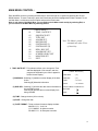
MAIN MENU CONTROL :
Enter the MENU screen by pressing the Menu button. Scroll through the 12 options by pressing the UP and
DOWN buttons. To enter a sub-menu, press the Enter button where the highlighted scroll bar is located. To exit
the Main Menu, scroll down to the Exit option and press the Enter button.
Note: In sub menu of the Main Menu, you can either exit the Menu mode entirely by selecting Exit, or
you can return to the Main Menu by selecting Return.
01
02
03
04
05
06
07
08
09
10
11
12
[ MAIN MENU]
TIME / DATE SET
SEQUENCE SET
TITLE SET
ALARM SET
MOTION SET
SYSTEM SET (I)
SYSTEM SET (II)
HDD / REC SET
ALARM REC SET
SCHEDULE REC SET
MONITOR SET
EXIT
1. TIME / DATE SET - This submenu allows you to change the Time
and Date displayed on the monitor, and also
program the information you’d like to appear in
the On-Screen Display.
(i) DISP MON : Selecting [Y] enables on screen display of the date
& time.
Selecting [N] hides this information.
(ii) DISP REC : Selecting [Y] will allow the date & time information to
be recorded into tape.
Selecting [N] prevents the on-screen display from
being recorded.
Note: The Menu is exited
automatically after 20 sec
of inactivity.
[TIME / DATE SET]
DISP MON
: [Y]
DISP REC
: [Y]
TIME
: 14:35:23
DATE
: 02/18/2003
DATE FORMAT: MM-DD-YY
RETURN
: [ ]
EXIT
: [ ]
(iii) TIME : Change the time (24 hour clock)
(iv) DATE : Change the date.
(v) DATE FORMAT : There are three formats to display the date:
MM-DD-YYYY : for U.S.A.
YYYY-MM-DD : for Asian countries.
DD-MM-YYYY : for European countries.
-8-
2. SEQUENCE SET - This submenu allows you to select how long
you’d like each channel to appear on-screen
before automatically switching to the next
channel in Sequence mode. The Dwell Time
is 0-59 seconds selectable for each of the 4
channels and for Quad mode.
NOTE : Channels without a camera, a Video Loss, or a Dwell
Time of zero will be skipped in sequencing.
3. TITLE SET - This submenu allows you to change the title of each
camera location (up to 8 characters), or remove the
titles from the on-screen display.
(i) DISPLAY : Selecting [Y] will enable the camera titles to appear
in the on-screen display. Selecting [N] will remove
all titles from appearing in the on-screen display.
(ii) CH 1 - 4 : Change the titles of each individual camera.
[SEQUENCE SET]
QUAD
: [03 SEC]
CH 1
: [03 SEC]
CH 2
: [03 SEC]
CH 3
: [03 SEC]
CH 4
: [03 SEC]
RETURN
:[
]
EXIT
:[
]
[TITLE SET]
DISPLAY
: [Y]
CH 1
: [CAMERA01]
CH 2
:[
C2
]
CH 3
:[
C3
]
CH 4
:[
C4
]
RETURN
: [ ]
EXIT
: [ ]
4. ALARM SET - This submenu allows you to enable / disable the camera’s PIR Alarm function by channel.
The PIR motion sensor is not included with the 3 observation cameras, but it is available as an
accessory (model ACC1401).
Note: The dome camera does not have the PIR motion detection feature
(i) ALARM : Selecting [OFF] disables PIR motion detection from triggering any alarm. Selecting [OSD] will
allow alarms to be triggered, and the letters “AL” will appear on the screen of the camera location where
the alarm is taking place. A third option, [OSD+BUZZER] will both display “AL” and emit a buzzer sound
in the event of an alarm.
(ii) CH 1-4 : Set the length of alarm time for each channel between 1~59 seconds. Additionally, you can
select the Alarm Input. The default setting is OFF - to activate the Alarm on a camera, change the
setting to N/O (Normally Open), N/C (Normally Close).
Note: Some alternative brand PIR motion sensors have a default setting of N.C (normally closed). In order
to activate the alarm on such a PIR motion sensor, change the setting to N.C
5. MOTION SET - This submenu allows you to enable / disable the Pixel-based Motion Detection function by
channel and set its Sensitivity level.
(i) MOTION : Selecting [OFF] disables the Pixel-based Motion Detection function. Selecting [OSD] will
allow motion to trigger alarms, and the letters “MD” will appear on the screen of the camera
location where the motion is taking place. A third option, [OSD+BUZZER] will display “MD”
and emit a buzzer sound in the event that motion is detected.
(ii) CHANNEL : Select which channels will have the Pixel Motion Sensing feature activated. The Sensitivity
level can be set to zero for a channel, which will disable the Motion Sensing ability for that
channel.
-9-
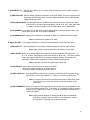
(iii) SENSITIVITY : Select the level of the Motion Sensing’s sensitivity level by channel.
Level 05 is the highest sensitivity, Level 01 is the least sensitive.
Level 00 deactivates Motion Sensing.
(iv) AREA : Select the area of the screen where the Pixel Motion Sensing feature will be active.
The digits below represent the area on the screen where motion is detected.
[ 00 ] - Whole screen.
[ 01 ] - Top left side of screen.
[ 02 ] - Top right side of screen.
[ 03 ] - Bottom left side of screen.
[ 04 ] - Bottom right side of screen.
[ 05 ] - Center of the screen.
01
02
00
05
03
04
6. SYSTEM SET ( l ) -This sub-menu allows you to configure various preferences on the system, related to
Monitor settings.
(i) KEY BUZZER: When set to [Y], the system will make a sound when a key is pressed on the remote
control or on the main panel of the monitor.
(ii) LOSS BUZZER: When set to [Y], the system will make a sound when a camera becomes
disconnected.
(iii) QUAD LINE: Activates and deactivates the border line in Quad mode.
(iv) BLANK COLOR: Choose between blue, gray or black as the background screen color in
Menu Mode.
(v) SLAVE OUT : When set to [ACTUAL], the system will output what is shown on-screen to another monitor
connected via the Slave Output. When set to [QUAD], the slave monitor will display Quad
mode, regardless of what’s appearing on the screen of the DVR Combo.
(vi) TITLE/TIME: Change the location of on-screen display for Time/Date and camera titles. T/R/B/L
represent Top / Right / Bottom / Left respectively. Therefore, for example, the setting
“TR/BL” would display the Title in the Top-Right corner of the screen, and the Time in
the Bottom Left corner.
(vii) PAN/TILT(CH1) : Activates Pan/Tilt mode to become accessible. For more information on Pan/Tilt
mode, refer to page 15.
(viii) ALARM OUT : Select the Alarm Out setting, which is defaulted to NO (Normally Open) for triggering
external devices.
(ix) DEFAULT SET: Selecting [Y] resets all programmed settings back to the default factory settings
(except for the time & date).
-10-
7. SYSTEM SET ( ll ) - This sub-menu allows you to configure various preferences on the system, related to
DVR settings.
(i) HDD INFO DISP: Sets the display settings for information on the HDD status. This can be displayed as a
percentage of HDD space used, or amount of Bytes available, or the HDD information
display can be set to OFF.
(ii) RS232 BAUD RATE: Sets the speed at which the RS 232 input and the computer communicate. Baud
Rate, which is the rate of data transmission, can be set to: OFF, 2400, 4800, 9600,
or 19200. For more information on the RS232 feature, refer to Appendix #4.
(iii) PASSWORD: If you select [Y], you will need to input a password when you enter the Main Menu, and
[N] will allow you into the menu without a password.
(iv) PASSWORD SET: Changes your password for accessing the Menu. The password must be 4 digits.
Note: the default factory password is “0000”
8. HDD / REC SET - This submenu allows you to set the Record parameters for your Hard Disk Drive.
(i) REC QUALITY: Sets the quality level of recording. Available settings are: Normal, High and Best.
Note: Higher quality recording consumes more memory on your HDD.
(ii) REC SPEED: Allows you to set the Images Per Second for recording. Available IPS settings are: 1, 2,
4, 8, 15, 30 & 60. The speed of 60 IPS is also known as “Real Time”. 1 IPS is the slowest
Time Lapse speed; it will allow for the longest recording durations as it records less
information. Please refer to Appendix # 5 for the different recording times.
Note: Audio does not record at a speed lower than 8 IPS.
(iii) REC SELECT: Selects which channels will be recorded to the HDD.
Select [0] to enable recording on a camera channel
Select [x] to disable recording on a camera channel
(iv) HDD CLEAR ALL: Select [MASTER] to delete all the contents in your Master HDD, then press the
button and you will be asked “REALLY?”. Select [Y] to confirm the HDD Clear.
Note: If you have a SLAVE HDD connected as well and the HDD Slave option
is set to [Y], then you may also choose to Clear the contents of your
Slave HDD.
(v) HDD OVERWRITE: Select [Y] to have the DVR automatically overwrite previously recorded video in the
event of the HDD becoming FULL. If you select “Y” it will display OVWR (Overwrite)
in the on-screen display. If you select “N”, the DVR will terminate recording once it
reaches its capacity.
Note: HDD Overwrite replaces the earliest recorded video with additional
video being recorded. When the HDD is Full and Overwrite is active,
the first piece of video that you recorded will be lost.
-11-
(vi) HDD SLAVE: Select [Y] to enable the system to check for a Slave HDD upon startup. Enabling HDD
SLAVE allows you to record to and playback from the Slave HDD (The HDD you
connect to the IDE-SUB on the back of the monitor). For more information regarding
how the Slave HDD backs up the Master HDD, please refer to page14.
Note: After activating the Slave HDD, you need to restart your system by turning
the Main Power Switch (located on the back of the monitor) OFF and then
ON again in order for the system to recognize the Slave HDD.
9. ALARM REC SET - This submenu allows you to configure the Recording parameters under the Alarm
condition.
(i) ALARM REC : This setting selects whether or not the DVR will record automatically when a Motion
Detection or a PIR alarm is triggered.
(ii) REC QUALITY : Selects the Recording Quality level for Alarm Recording (from Normal, High, or Best).
(iii) REC SPEED : Sets the speed of Alarm Recording from 60 / 30 / 15 / 08 / 04 / 02 / 01 IPS.
(iv) REC DURATION : Selects how long the DVR will automatically record after an alarm is triggered.
Available duration times are: [ 20SEC / 30SEC / 1MIN / 2MIN / 5MIN and CONTIN]
CONTIN refers to Continuous recording.
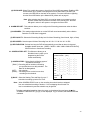
10. SCHEDULE REC SET - This Submenu allows you to
Schedule times in which you’re
programming the DVR to
record automatically.
(i) SCHEDULE REC : Select from the following types of
Scheduled recordings:
[DAILY] - Recording will be carried out according
to a specified time on a daily schedule. The
Date will be disregarded.
[OFF] - No schedule.
[ONCE] - Recording will be carried out one time,
according to the schedule.
(ii) N0-N7 - Select the Starting Time and Date for up to 7
scheduled recordings, plus the End Time.
[S CH E DU LE R EC SE T ]
SC H ED U LE R E C : [ OFF ]
N 0 : _ _ / _ _ _ _ : _ _ -> _ _ / _ _ _ _ : _ _
N 1 : _ _ / _ _ _ _ : _ _ -> _ _ / _ _ _ _ : _ _
N 2 : _ _ / _ _ _ _ : _ _ -> _ _ / _ _ _ _ : _ _
N 3 : _ _ / _ _ _ _ : _ _ -> _ _ / _ _ _ _ : _ _
N 4 : _ _ / _ _ _ _ : _ _ -> _ _ / _ _ _ _ : _ _
N 5 : _ _ / _ _ _ _ : _ _ -> _ _ / _ _ _ _ : _ _
N 6 : _ _ / _ _ _ _ : _ _ -> _ _ / _ _ _ _ : _ _
N 7 : _ _ / _ _ _ _ : _ _ -> _ _ / _ _ _ _ : _ _
R ETU R N
: { J]
EX IT
:{J ]
Note : When SCHEDULE REC is set up, the recording time should not be overlapped
from one scheduled recording to another. If it is overlapping this will result in a
loss in recorded activity and the schedule may be ignored.
To delete a scheduled recording, place the cursor on the selected time and press the key.
"CURRENT LINE DELETE? [Y] / [N]” is then displayed. If [Y] is selected, the selected schedule
is deleted.
-12-
11. MONITOR SET - This submenu allows you to adjust the Picture settings of the monitor.
You can switch between Full or Quad screen views while adjusting the monitor settings by
pressing the and keys
(i) CONTRAST : Changes the contrast of the picture.
(ii) BRIGHT : Changes the brightness of the picture.
(iii) COLOR : Changes the color of the picture.
(iv) TINT : Changes the tint of the picture.
(v) SHARPNESS : Change the sharpness of the picture.
12. EXIT - Exits the MENU mode.
SEARCH :
The DVR allows you to easily find sections of recorded video using the Search feature.
Press the SEARCH button to access the “PLAYBACK SEARCH SET” menu.
(1) LAST RECORD
(2) FULL LIST
(3) ALARM LIST
(4) TIME SEARCH
(5) EXIT
[PLAYBACK SEARCH SET]
: Plays the most recent recording.
: Shows a listing of all recorded video on the HDD, sorted by time.
: Shows a listing of all recorded video triggered by an Alarm.
: Finds video recorded on a specific date and time that is entered.
: Exits Search mode.
A listing of up to 1000 recordings can be stored in both the ALARM LIST and the FULL LIST. You can scroll
through Recordings using the and keys, and navigate between Pages of Recordings using the and
keys. To view a selected piece of video on the list, press the PLAY / Enter button on the highlighted recording.
The DVR will play that video. You can stop the video at any time by pressing the STOP button.
Note: When HDD SLAVE is set to “Y”, both the SLAVE and MASTER HDD’s are searchable.
You can navigate between the Master HDD Search and the Slave HDD Search by pressing
the and keys.
-13-
PLAYBACK OPTIONS
Upon pressing the PLAY button, one of the Playback Search menus will appear. These
Playback menus are the same as the Search options described on page 13. Whichever Search
option you last accessed will dictate which Playback menu that appears upon pressing PLAY.
For example, if the last Search option used was a Time Search, then pressing PLAY will bring
up the Playback Time Search. If the last Search option utilized was a Last Record, then
pressing play will simply play the most recent recording.
FAST REWIND AND FAST FORWARD
You can increase the speeds of Fast Forward and Rewind on the DVR.
While in PLAY mode, pressing the FF / REW button once initiates FF / REW at a speed of 2X.
Pressing the FF / REW button a second time increases the FF / REW speed to 4X.
Pressing the FF / REW button a third time increases the FF / REW speed to 8X….
The maximum FF / REW speed is 128X.
To terminate FF / REW, press the PLAY button, which will Pause the screen. You can then retry
FF / REW, or proceed to press PLAY again for standard Playback.
MULTIPLEXING FUNCTION IN PLAYBACK
Because of the Multiplexing function of the DVR, you can switch between individual channels
during playback and watch each one in Full-Screen. Press the Ch1-Ch4 buttons to view Full
Screen channels in Playback mode.
MASTER & SLAVE:
The Master HDD is the hard disk-drive in the cabinet accessible on the front of the monitor. On
the back of the monitor there is an IDE-SUB input for connecting another HDD to serve as a
backup to the Master HDD, providing extra storage space.
To connect a Slave HDD, you will need an External IDE drive with a built-in power supply.
Please contact the manufacturer or visit www.strategicvista.com for more information regarding
how to obtain an accessory External HDD Bay with IDE connection.
Note that once you have connected a Slave HDD, it needs to be activated in the HDD SLAVE
option of the HDD / REC SET submenu (refer back to page 12 for further details).
Note: any HDD that you connect to the system must be Cleared.
When recording to the Master HDD becomes Full, the Slave HDD commences receiving the
earliest recorded data from the Master HDD. Therefore, data is not lost, as it gets transferred to
the Slave HDD. The most recent recordings are found on the Master HDD.
-14-
PAN / TILT ZOOM:
The monitor is equipped with a built-in Pan/Tilt Zoom feature, which is only available when used in
conjunction with a compatible Pan/Tilt Zoom Dome camera (model SG7380).
Please refer to www.strategicvista.com for more information on the available accessories (sold separately).
The Pan/Tilt Zoom feature supports “Pelco D” protocol, and operates via the 6 Pin DIN connection on
Channel 1. To access and operate the PTZ feature, follow these instructions:
1)
2)
3)
4)
5)
6)
Connect the compatible Pan/Tilt Zoom Dome camera to Channel 1;
Go to the SYSTEM submenu and set the PAN/TILT(CH1) option to “Y”
You will see a contracted screen with a blue border. Use the Arrow keys to move sideways, and
ENTER, to select whether to MOVE, ZOOM, or FOCUS the camera. (note: Focusing is currently not
available on the SG7380 camera).
Enter the Pan/Tilt Zoom mode by holding the PAN/TILT key on the monitor for 3 seconds, or press
the Pan/Tilt button on the remote control;
If you have selected MOVE, you can use all four arrow keys to Pan and Tilt in all directions. If you
selected ZOOM or FOCUS, use the ▲▼arrow keys to Zoom / Focus IN / OUT.
Select and press the ENTER key on the EXIT option to escape the Pan/Tilt mode.
Note: The system automatically exits the Pan/Tilt mode after 20 seconds of inactivity.
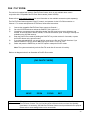
Refer to the diagram below for an illustration of Pan/Tilt Zoom mode
[CH1 PAN/TILT MODE]
MOVE
ZOOM
FOCUS
EXIT
Important Note: The dome camera that is included with this system, (model SC21CD5444UQ-A80) is not a
Pan/Tilt Dome Camera. This is a fixed lens dome camera and does not have the capability
listed above. An accessory, SG7380 Pan/Tilt Dome Camera can be purchased for this purpose.
Please refer to www.strategicvista.com for more details.
-15-
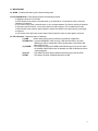
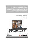
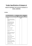
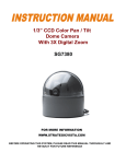
CONTROL - BACK PANEL :
10
2
6
CH1
CH3
CH2
CH4
9
7
12
USB
RS-232
SENSOR INPUT
SENSOR
OUTPUT
USB
POWER
MAIN S/W
+ -
+ -
+ -
+ -
+ -
VIDEO INPUT
CH2
CH4
SLAVE
OUT
AUDIO INPUT
MONITOR
OUT
IDE-SUB
CH3
VIDEO
CH1
AC INPUT
1
2
3
4
AUDIO
AC100-240V,50/60Hz
11
1
3
4
5
8
1. BNC Camera Inputs - Channel 1-4 camera inputs (for cameras with BNC Video outputs)
2. 6 Pin DIN Camera Inputs - Channel 1-4 Camera inputs (for cameras with 6 Pin DIN camera outputs).
3. RCA Audio inputs - Channel 1-4 Audio inputs (for cameras with RCA Audio outputs)
4. Slave A/V Out - Audio/Video Out signal for transmitting to a Slave Monitor or VCR.
5. Monitor A/V Out - Audio/Video output to another monitor.
6. Alarm Function Terminals - These terminals are used to connect external motion sensors.
7. Sensor Output - These terminals are used to connect external Alarm Output devices, such as a
siren or security light.
8. IDE-SUB - This connector is used to connect an external Slave HDD.
9. RS-232C Terminal - Connects to the RS-232C terminal on your computer. For more information on
RS-232C communication, refer to Appendix #4.
10. MAIN POWER SWITCH - Used to turn the system ON or OFF.
11. AC INPUT – Connects to a Power Plug (AC100-240V, 50/60Hz).
12. USB Port – Connects to a PC using a USB cable
-16-
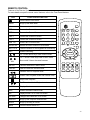
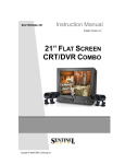
REMOTE CONTROL:
Features of the Remote Control.
For more details on specific remote control features, refer to the Front Panel features.
KEY
FUNCTION DESCRIPTION
Turns Power to unit On/Off.
MENU
Brings up the Main Menu
1-4
Allows user to select individual cameras
FRZ 1
Freezes the Channel 1 screen
FRZ 2
Freezes the Channel 2 screen
FRZ 3
Freezes the Channel 3 screen
FRZ 4
Freezes the Channel 4 screen
PAN TILT
Enters Pan/Tilt Zoom mode.
AUDIO SEL
Selects the Audio channel in Quad mode
KEY LOCK
Locks the buttons on the keypad from functioning
REC
Initiates Recording
MENU
3
2
1
FRZ1
5
4
6
FRZ2
9
8
7
FRZ3
PAN/ TI LT AUDI O KEY LOCK FRZ4
SEL
REC.
ENTER
UP / DOWN arrow keys, used in Menu mode.
/ VOL
LEFT / RIGHT arrow keys used in Menu mode.
Also control Volume decrease/increase.
ENTER
Confirms selections in Menu mode
FRZ ALL
Used to Freeze the current screen
Rewinds video in Playback mode
VOL
VOL
IN
ZOOM
OUT
QUAD
SEQ
FOCUS
NEAR
FAR
PI P
SEARCH
R-SEARCH P-SEA
RCH EVENT
PI P-SUB
ALRS
Initiates video Playback mode and Pauses video
Stops video Playback
Fast Forwards video in Playback mode
QUAD
Displays Quad screen
SEQ
Initiates automatic channel scan
PIP
Displays either PIP or Dual PIP screen
PIP-SUB
Changes the Subscreen in PIP mode
SEARCH
Brings up the Playback Search mode
EVENT
Brings up a listing of Events
ALRS
Turns the Alarm sound OFF.
-17-
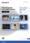
STANDARD WIRED CAMERA:
2
1
3
5
4
1.
2.
3.
4.
5.
Camera Lens – Delivers high quality image by using a 1/4” CCD Image Sensor
Speaker – Delivers sound from the monitor to the camera
Camera Input – Connects cable to the monitor
Bracket – Metal bracket connects to camera for mounting to walls, ceilings or table
Microphone – Picks up sound around the camera
INSTALLATION
A. Camera Unit
Permanent installation using metal camera bracket
IMPORTANT NOTE:
Keep camera installed away from direct sunlight. Also avoid places where humidity
is high or unable to protect from rain. The mounting bracket must be attached to a structural
device such as wall stud or ceiling rafter using suitable fastener.
-18-
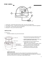
DOME CAMERA:
2
1
4
3
1.
2.
3.
4.
Camera Lens – Delivers high quality image by using a 1/4” Color CCD Image Sensor
Plastic Bubble Housing - Smoked acrylic housing protects lens and provides an unobtrusive appearance
Camera Input – Connect cable to the back of the monitor
Microphone – Picks up sound around the camera
INSTALLATION
A. Camera Unit
Permanent installation using metal camera bracket
1.) Connect the 65 ft Din cable (included with the dome
camera) to the wired lead of the dome camera
2.) Attach the adaptor plate on the ceiling or wall, using
the 3 screws provided (M3X20 screw).
M3
3.) Twist the base of the dome camera on to the
adaptor plate on the ceiling or wall.
Note: Do not hold the clear plastic bubble or swivel
when you attach the dome to the adapter plate
4.) Connect the other end of the 65 ft cable to the
Camera input on the back of the monitor
5.) Connect power to the observation system
IMPORTANT NOTE:
Keep camera installed away from direct sunlight. Also avoid places where humidity
is high or unable to protect from rain. The mounting bracket must be attached to a structural
device such as wall stud or ceiling rafter using suitable fastener.
-19-
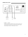
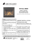
CAMERA INSTALLATION :
CH1
CH3
CH2
CH4
USB
RS-232
SENSOR INPUT
SENSOR
OUTPUT
USB
POWER
MAIN S/W
+ -
+ -
+ -
+ -
+ -
VIDEO INPUT
CH2
CH4
SLAVE
OUT
AUDIO INPUT
MONITOR
OUT
AC INPUT
1
2
3
IDE-SUB
CH3
VIDEO
CH1
4
AUDIO
AC100-240V,50/60Hz
1. CAMERA 1- 4 INPUTS
Connect one end of the supplied 65 ft cable to the first wired camera, and
the other end to the camera 1 input on the back of the monitor. Connect
the other supplied cameras to Camera Input 2, 3 and 4
-20-
TROUBLE SHOOTING:
If the system does not function properly, please check the following points.
PROBLEM
SOLUTION
Too dark or bright picture
Readjust the CONTRAST or
BRIGHTNESS controls
Poor picture quality
Clean the camera lens. Readjust the
CONTRAST or BRIGHTNESS controls
Picture but no sound
Adjust the volume
Picture, but no control
Reset the system by turning off the main
power and unplugging the system. Turn
the system on again after 30 seconds
Shrinking Picture
Check the condition of the power source
NO POWER
Make sure the AC Cord is connected
properly and the power switch is “ON”
NO VIDEO
Check the cable connected at
the Monitor, and at the camera
for any loose connection.
Picture flickering or over
exposed
Make sure the camera is not facing any
direct light or sunlight
Slave HDD not readable
Check the jumper PIN connection.
Activate the Slave HDD in the Menu option
HDD SLAVE.
HDD not found
Re-insert HDD as per Appendix #1.
Make sure that the HDD cartridge is
locked.
Keypad doesn’t work
Remove the Key Lock
Recording stopped
The HDD is Full, and Overwrite is not
enabled
MONITOR
WIRED
CAMERAS
DVR
-21-
TECHNICAL SPECIFICATIONS:
MONITOR
Picture Tube :
Horizontal Resolution :
Camera Capable :
Camera Input :
Input Signal :
Power Consumption :
AC INPUT :
Weight :
Dimension :
21” Color Quad Screen
450 lines
Up to 4
4 Mini Din / 4 BNC
Composite 1 Vp-p (V:0.714Vp-p, Sync : 0.3Vp-p)
105Watts (Max.)
100 ~ 240 Volts 50 / 60 Hz
57 Lbs. (26Kg)
19.7”(W) X 18.6”(W) X 18.2”(W)
STANDARD CAMERA
Image Device
Resolution
Shutter control
Power requirement
Illumination
Operating Temperature
Weight:
Dimensions:
1/4” CCD image sensor
330 TV Lines
Auto 1/60 - 1/100,000
Powered from monitor via cable
0.5 LUX @ F2.0
-4°F – 122°F (-20°C to 50°C)
12 oz (340 Grams)
3” (W) x 3.6”(D) x 3.5”(H)
DOME CAMERA
Image Device
Resolution
Video Output
Shutter control
Power requirement
Illumination
Lens
Operating Temperature
Dimensions
1/4” CCD Color image sensor
350 TV Lines
1.1 Vp-p at 75 ohms
Auto 1/60 - 1/100,000
Powered from monitor via cable
1.0 lux
3.6 mm
14°F – 113°F (-10°C to +45°C)
5” (Diameter) x 3.5” (H)
DVR
Recording Time:
Recording Speed :
HDD Capacity :
Recording Video Quality :
Recording Mode :
Playback :
Video Display :
Compression Rate:
View Resolution :
Record Resolution :
Display Frame :
Recording Frame :
OS :
100 hour Real Time / 2250 hour recording
(with 80 GB HDD at Normal Video Quality)
60 Field / Sec.
20GB(Min) ~ 300GB(Max.)
Normal, High, Best
Normal Rec, Alarm Rec, Schedule Rec
Normal Play Mode, 2X / 4X / 8X / 16X / 32X / 64X / 128X
Normal Mode (Full / Quad), Sequential Mode, PIP Mode
5~20K Byte / Frame
720 (H) X 480 (V)
640 (H) X 224 (V)
30 Frames/sec
Max.60 IPS
Embedded RTOS
Because our products are subject to continuous improvement, SVII and its subsidiaries reserve the right to modify product
design and specifications without notice and without incurring any obligation. E&OE
-22-
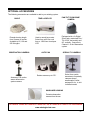
OPTIONAL ACCESSORIES
The following accessories are available to add to your existing system.
CABLE
Extends viewing length
from Camera to monitor.
Available In 65, 100 and
250 ft lengths
OBSERVATION CAMERAS
TIME LAPSE VCR
Used to record key events.
Select from a 40 hour real
time or 1280 Hour time lapse
VCR
AUTO PAN
PAN/TILT ZOOM DOME
CAMERA
Equipped with a 3x Digital
Zoom and a motorized Pan /
Tilt of 320° horizontally and
90° vertically. Connects to
Channel 1 of the Observation
system.
SPECIALTY CAMERAS
Rotates camera up to 270°
Accessory PIR motion
sensor observation
system camera
Select from a wide
assortment of specialty
cameras (dome,
weatherproof, bullet,
waterproof, etc., to suit
individual needs
SUNSHADE HOUSING
Protects observation
camera from the sun
TO ORDER THESE ACCESSORY ITEMS OR FOR A COMPLETE LINE OF ACCESSORIES
www.strategicvista.com
-23-
APPENDIX #1 – INSTALLING the HDD
The HDD serves the same purpose in a DVR as a video cassette does in a VCR.
However, installing the HDD is a bit more complicated. Please follow the next steps
carefully in order to ensure proper installation.
The compartment located on the front panel of the DVR is the removable Cartridge Casing in which you
insert the HDD. The various parts of the Cartridge Casing are labeled for your reference.
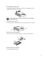
1.
Remove the Cartridge Casing from the DVR
Lift the Handle and pull towards you. The Cartridge Casing will slide out of the DVR.
Cartridge Casing
1. Keyhole
2. LED indicator lights
(Power indicator & HDD Access indicator)
3. Handle
YOU MAY FIND THAT THE CARTRIDGE CASING IS LOCKED. IN THIS CASE, SKIP
AHEAD TO STEP 8 TO FIND INSTRUCTIONS ON UNLOCKING THE CABINET, THEN
RETURN TO STEP 2.
2.
Remove the Cover from the Cartridge Casing
a) Unclip the release latch with the word “OPEN” printed beside it by gently pushing on the latch.
b) Slide the cover off the Cartridge Casing.
-24-
3.
Connect the HDD into the Cartridge Casing
Take the Hard Disk Drive and Connect the two cables from the back of the Cartridge Casing to the HDD.
The cables should be pushed in firmly, but not forcibly.
The 4 Pin connection is the DC Power cable, and the wider cable is the standard Hard
Drive IDE type connection.
4.
Secure the HDD in the Casing (optional)
Use screws and tighten them, positioning the HDD into place. This step is optional, but it is recommended.
5.
Slide the top Cover over the Cartridge Casing
Slide the Cover forward over the Cartridge Case. Ensure it is secured in place over the release latch.
6.
Reinsert the Cartridge Casing into the DVR
Fully insert the Cartridge Case into the DVR.
-25-
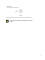
7.
Lock the Cabinet
Lock the cabinet by turning the key clockwise.
A
(locked)
B
(unlocked)
If you need to unlock the cabinet, turn the key counter-clockwise from the position shown above.
IF YOU DO NOT LOCK THE CABINET, THE DVR SYSTEM WILL NOT FUNCTION
PROPERLY.
-26-
APPENDIX #2 – CONNECTION TO A SLAVE
MONITOR & STANDARD VCR
CH1
CH3
CH2
CH4
USB
RS-232
SENSOR INPUT
SENSOR
OUTPUT
USB
POWER
MAIN S/W
+ -
+ -
+ -
+ -
+ -
VIDEO INPUT
CH2
CH4
SLAVE
OUT
AUDIO INPUT
MONITOR
OUT
AC INPUT
1
2
3
IDE-SUB
CH3
VIDEO
CH1
4
AUDIO
AC100-240V,50/60Hz
VCR
MONITOR
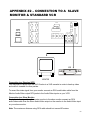
Connection to a Standard VCR
You may wish to record from the DVR Combo to a VHS cassette in order to back up video
and make it viewable for other parties.
To record the video signal from your monitor connect an RCA audio/video cable from the
Monitor Audio/Video output RCA jacks to the Audio/Video inputs on your VCR.
Connection to a Slave Monitor
To duplicate the signal from the master monitor to the slave monitor connect an RCA
audio/video cable from the Slave Audio/Video output on the monitor to the Audio/Video input
on your slave monitor.
Note: The maximum distance using RCA cable should not exceed 20 meters
-27-
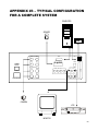
APPENDIX #3 – TYPICAL CONFIGURATION
FOR A COMPLETE SYSTEM
COMPUTER
SENSOR
HDD
CH1
CH3
CH2
CH4
USB
RS-232
SENSOR INPUT
SENSOR
OUTPUT
USB
POWER
MAIN S/W
+ -
+ -
+ -
+ -
+ -
VIDEO INPUT
CH2
CH4
SLAVE
OUT
AUDIO INPUT
MONITOR
OUT
AC INPUT
1
2
3
IDE-SUB
CH3
VIDEO
CH1
4
AUDIO
AC100-240V,50/60Hz
CAMERA
VCR
MONITOR
-28-
APPENDIX #4 - RS232 Remote Protocol
The RS232 / Alarm input allows you to control the DVR system from your PC. In order to achieve this, you will require an RS232 COM
Port communication program installed on your PC. There are many of these software programs available on the internet, some of which
are free. Please contact the manufacturer SVC if you require this software, or visit www.strategicvista.com for more information.
Use an RS-232C cable to connect the DVR Combo to your computer.
The remote connection on the DVR uses 8 data bits, 1 start bit, and 1 stop bit. Below is an example of the data stream with the control
codes shown.
ACT – OxFF
OxCO
ID
CODE
STOP – Ox7F
The PC keyboard simulates the DVR keypad. For example, pressing “r” will make the DVR stop.
Note that the letters are case sensitive. Below is a list of corresponding keys, and their codes:
FUNCTION
CH1
CH2
CH3
CH4
PIP_SUB
STOP
ALRS
REW
QUAD
PIP
SEQ
MENU
PAN/TILT
POWER
AUDIO_SEL
EVENT
CODE
0x31
0x32
0x33
0x34
0x6D
0x72
0x68
0x74
0x35
0x36
0x37
0x39
0x76
0x57
0x58
0X6F
ASCII
1
2
3
4
m
r
h
t
5
6
7
9
v
W
x
o
FUNCTION
ENTER
UP
DOWN
RIGHT
LEFT
CH1_FRZ
CH2_FRZ
CH3_FRZ
CH4_FRZ
REC
P-SEARCH
R-SEARCH
KEYLOCK
PLAY/PAUSE
FF
CODE
0x42
0x43
0x44
0x45
0x46
0x47
0x48
0x49
0x4A
0x6E
0x70
0x71
0x75
0x41
0x73
ASCII
B
C
D
E
F
G
H
I
J
n
p
q
u
A
s
-29-
APPENDIX #5 – RECORDING TIME (in hours)
BASED ON 80G H.D.D
QUALITY / FRAME
RATE
BEST
HIGH
NORMAL
60 IPS
34 Hours
70 Hours
100 Hours
30 IPS
58 Hours
90 Hours
140 Hours
15 IPS
80 Hours
144 Hours
210 Hours
08 IPS
160 Hours
256 Hours
406 Hours
04 IPS
242 Hours
408 Hours
660 Hours
02 IPS
476 Hours
768 Hours
1158 Hours
01 IPS
930 Hours
1270 Hours
2284 Hours
60 IPS is equal to 30 frames per second. 1 IPS is equal to 0.5 frames per second.
Note: Audio is not available at recording speeds lower than 8 IPS.
-30-
APPENDIX #6 – RECORDING TIME (gigabytes per hour)
QUALITY / FRAME
RATE
BEST
HIGH
NORMAL
60 IPS
2.31GB/Hour
1.12GB/Hour
0.800GB/Hour
30 IPS
1.35GB/Hour
0.878GB/Hour
0.571GB/Hour
15 IPS
0.990GB/Hour
0.555GB/Hour
0.380GB/Hour
08 IPS
0.499GB/Hour
0.311GB/Hour
0.197GB/Hour
04 IPS
0.328GB/Hour
0.196GB/Hour
0.121GB/Hour
02 IPS
0.168GB/Hour
0.104GB/Hour
0.069GB/Hour
01 IPS
0.086GB/Hour
0.063GB/Hour
0.035GB/Hour
-31-
CARE AND MAINTENANCE:
Please follow these instructions to ensure proper care and maintenance
of this system
Keep your monitor and camera dry. If it gets wet, wipe it dry immediately.
Use and store your unit in normal temperature environment. Extreme
temperatures can shorten the life of the electronic devices.
Handle the monitor carefully. Dropping it can cause serious damage
to the unit.
Occasionally clean the unit with a damp cloth to keep it looking new.
Do not use harsh chemicals, cleaning solvents, or strong detergents
to clean the unit.
Keep the unit away from excessive dirt and dust. It can cause
premature wear of parts.
-32-