1
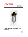
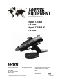
EQUIPMENT OPERATION MANUAL Hysol® 175-AIR P/N 98036 Hysol® 175-AIR-HT P/N 98040 Loctite Americas 1001 Trout Brook Crossing Rocky Hill, CT 06067-3910 Loctite Canada Inc. 2225 Meadowpine Boulevard Mississauga, Ontario L5N 7P2 Loctite Brazil Av. Prof. Vernon Krieble, 91 06690-11-Itapevi São Paulo-Brazil Loctite is a trademark of Loctite Corporation, U.S.A. Copyright 2001. Loctite Corporation. All rights reserved. Loctite Company de México, S.A.d e C.V. Calzada de la Viga s/n, Fracc. Los Laureles Loc. Tulpetlac, C.P. 55090 Ecatepac de Morelos, Edo. de México, México www.loctite.com A Company Data in the manual is subject to change without notice. 985067 06/01 Contents 1. 1.1. 1.2. Please Observe the Following................................................................................... 2 Safety .......................................................................................................................... 2 Items supplied.............................................................................................................. 2 2. Description................................................................................................................. 2 3. Technical Data............................................................................................................ 3 4. Installation.................................................................................................................. 3 5. 5.1. Operation.................................................................................................................... 4 Adhesive Flow Rate Adjustment ................................................................................... 4 6. Application Hints........................................................................................................ 5 7. Troubleshooting......................................................................................................... 5 8. Care and Maintenance ............................................................................................... 6 9. Accessories and Spare Parts .................................................................................... 6 10. Warranty..................................................................................................................... 8 11. Appendix. ................................................................................................................... 9 12. Exploded View.......................................................................................................... 10 13. Parts List. ................................................................................................................. 11 Page 1 1. Please Observe the Following 1.1.Safety Do not touch the nozzle or molten adhesive with bare skin as they are hot - the operating temperature of the Loctite® Hysol® 175-AIR and 175-AIR-HT applicators is approximately 400ºF (200ºC). Protective gloves should always be worn. Careless handling can cause skin burns. If molten adhesive comes into contact with the skin immerse the affected area immediately in plenty of cold water. Seek medical advice if necessary. In addition to the safety instructions herein, any statutory regulations, local fire insurance regulations, or other generally valid “regulations for accident prevention” must be complied with when using this tool. • Never use the tool if it is damaged in any way. • Do not use this tool in damp rooms, outdoors while it is raining, or where there is high humidity. • Do not use this tool in the vicinity of any heat-sensitive materials, or any flammable materials, liquids, or gases. • Only use extension cables that meet the specification shown in “Technical data”. • Never pull on the tool’s connecting cable. 1.2. Items supplied Loctite® Hysol® 175-AIR Pneumatically-driven Hot Melt Cartridge Dispenser, fitted with 383°F (195°C) thermostat (suitable for standard EVA-based hotmelt adhesives) Valve body air line adaptor Plastic Stand Manual Loctite® Hysol® 175-AIR-HT Pneumatically-driven Hot Melt Cartridge Dispenser, fitted with 400°F (204°C) thermostat (suitable for polyamide hotmelt adhesives) Valve body air line adaptor Plastic Stand Manual 2. Description The Loctite® Hysol® 175-AIR and 175-AIR-HT are the highest output, hand-held industrial hotmelt applicators available. With its two powerful 250W stainless steel cartridge heaters, they are capable of dispensing up to 9 lbs. of molten hotmelt per hour; yet only take 10 minutes to warm up from cold. Supported by a range of adhesive formulations, the Loctite® Hysol® 175-AIR and 175AIR-HT are suitable for most applications. Also, the Loctite® Hysol® 175-AIR and 175AIR-HT systems are solvent-free and non-toxic, so there are none of the environmental problems often associated with other adhesive applicators. Designed to comply with worldwide safety standards, the Loctite® Hysol® 175-AIR and 175-AIR-HT also feature a totally enclosed heater housing, and are fitted with thermal fuse protection. Page 2 3. Technical Data Dimensions (L x H x W): Diameter of adhesive inlet: approx. 11 13/16” x 9 15/32” x 2 17/32” (Approx. 300 x 240 x 65 mm) approx. 3 lbs. (1.4 Kg) 10 ft (3 m) long 110-120 VAC 50/60Hz 500W 10 minutes 175-AIR approx. 383°F (195°C) 175-AIR-HT approx. 400°F (204°C) 1 11/16” (43 mm) Extension cable: Wire cross section: max. 65ft (20 m) long at least 16 a.w.g. (1.5 mm2) Air Supply / Pneumatic Minimum Maximum Total weight: Connection cable with mains plug: Operating voltage: Power consumption Heating up time: Operating temperature: 45 p.s.i. (3 bar) 100 p.s.i. (7 bar) 4. Installation Before using the tool for the first time check it carefully for signs of external damage. If any transit damage is found DO NOT USE THE TOOL - return it to your supplier immediately. Steps 1 – 5 should be followed before connection to the mains supply: 1. 2. 3. 4. 5. Insert the applicator stand into the grooves at the base of the handle. Stand applicator on a flat surface. Connect the air supply hose to a clean, dry and regulated air supply using the Quick-Disconnect fitting provided (use of a filter/regulator is recommended) Pull piston back fully and rotate upwards. Load two adhesive cartridges into the barrel of the tool and push fully forward. Rotate the piston down and slide forward fully until it contacts the rear of the adhesive cartridge - it should engage about 5/16" (6-8mm) into the applicator barrel. 4 5 3 2 USERS AIR SUPPLY 6. 7. 8. 1 Connect tool to main power supply. Red ‘Power On’ indicator light illuminates. Allow the applicator to thoroughly warm up for 10 minutes. Do not attempt to operate the applicator until this time has elapsed. Page 3 5. Operation Normal use: • Fit the stand and place the applicator in an upright position on a flat surface. • Plug the applicator into the power supply socket, and switch on the power. Wait 10 minutes for the applicator to reach its normal operating temperature. • Squeeze the trigger to advance the piston and extrude molten adhesive through the nozzle. • To stop extruding adhesive simply release the trigger. During use, the piston will advance into the barrel as the trigger is pulled. A point will be reached where the piston no longer advances, and the sound of air escaping can be heard - this indicates that the applicator needs reloading. • Release the trigger. • Pull the piston back. • Insert a new adhesive cartridge. • Operate the tool normally. 5.1. Adhesive Flow Rate Adjustment The flow rate of adhesive is dependent on the air pressure to the piston, and this is adjusted by varying the setting of the pressure regulator on the air supply to the applicator. The air pressure operating range for the applicator is: Minimum 45 p.s.i. (3 bar) Maximum 100 p.s.i. (7 bar) USERS AIR SUPPLY . Page 4 6. Application Hints As with all adhesives, performance depends on conditions of use. Suggestions or recommendations contained herein are for guidance only, since actual conditions of use are outside the supplier’s control. • • • • • • • • • Ensure that the surfaces to be bonded are dry, free from dust, grease, and loose particles. Apply adhesive to one surface only. Bring the two surfaces together immediately, quickly making any further adjustments. Hold the joint for 20 – 30 seconds to complete the bond. When gluing dissimilar materials, apply the adhesive to the least heat conductive of the two. On materials that are cold to the touch, a better bond can be made by prewarming them before applying adhesive. Surplus adhesive can be trimmed using a sharp knife once it has cooled. Should molten adhesive drip onto a smooth or polished surface, allow it to cool completely before removal. Spots or blobs of adhesive are recommended for work pieces having a large surface area, or which are particularly long. Applying the adhesive in wavy lines is recommended for gluing textiles or similar materials. Foam materials, like polystyrene, can be easily bonded to other surfaces. However the adhesive must be applied to the other surfaces, not to the foam. Use only genuine Loctite® Hysol® adhesives to ensure reliable performance. Loctite® Hysol ® adhesives are non-toxic and non-flammable. 7. Troubleshooting Before proceeding with any repair or maintenance operation disconnect the tool from the mains electricity supply. Glue “Backup” and “Meltdown” “Backup” occurs when hot molten adhesive in the glue chamber is forced back between the barrel wall and the outside surface of the adhesive cartridge and piston. Once this adhesive cools, it may lock the adhesive cartridge in the barrel, preventing, or at least restricting, normal extrusion. By far the most likely cause of backup is allowing insufficient warm-up time before operating the tool (the molten glue in the glue chamber cannot escape forwards because the nozzle is blocked, due to being insufficiently warm). In the vast majority of cases the backup self-clears once the tool, having fully reached operating temperature, is operated again. "Meltdown" occurs when the rear of the adhesive cartridge softens to the extent that it is not rigid enough to drive the cartridge forward without collapsing. As with backup, the molten adhesive can solidify, potentially locking the cartridge and / or piston into the barrel. Meltdown is caused by leaving the tool switched on for extended periods of time without operating it. It is recommended that, if the tool is to be left standing for forty minutes or more, it should be switched off and only switched back on when preparing to use it again. The Loctite® Hysol® 175-AIR and 175-AIR-HT tools are fitted with specially coated pistons which have non-stick characteristics far superior to any PTFE coating; this minimizes the effect of any backup or meltdown, should it occur. Page 5 FOR ANY REPAIRS OR ADJUSTMENTS – OTHER THAN THOSE DETAILED IN THIS MANUAL – PLEASE CONTACT 1-800-LOCTITE. 8. Care and Maintenance Every attempt has been made to make this exceptionally powerful tool both reliable and trouble-free. However the following precautions should be noted: • Make sure that the applicator is up to temperature before attempting to operate. • Do not leave the applicator switched on for long periods without use. If the applicator is not to be used for forty minutes or more, switch it off and restart when required. • Keep the applicator upright when not in use, never lay it on its side. Always use the stand provided, or the optional bench stand or suspension unit (see Spares and Accessory lists at the end of this manual). • Do not use excessive force on the trigger. Ensure that the tool has fully warmed up before use. • Keep the nozzle clean to prevent adhesive build-up. This is easily done by wiping the nozzle with clean paper or cloth while the nozzle is still warm. 9. Accessories and Spare Parts Spare Parts Part Number 2-Part Nozzle Assembly - supplied with tool Nozzle Adapter Applicator Stand Nozzle Shroud Kit, Qty 5 Barrel PTFE Barrel Support Assembly Piston Support Assembly Piston Assembly Piston Support O-ring Kit, Qty 5 Thermostat Assembly, 383°F (195°C) Thermostat Assembly, 400°F (204°C) (for polyamides) Heater Assembly 120 Volts PCB Assembly Thermal Fuse, Spacer Assembly Valve Body Airline Adapter 985078 985088 985069 985223 985071 985091 985093 985095 985234 985079 985068 985080 985083 985076 985240 Heater Housing Kit For 98036 (EVA Adhesive) Qty 1 – O-ring Heater Housing, item 5 Qty 1 – Heater Housing, item 6 Qty 1 – Ground Screw, item 35 Qty 1 - Lock Washer, item 39 985227 Heater Housing Kit For 98040 (Polyamides Adhesives) 985237 Qty 1 – O-ring Heater Housing, item 44 Qty 1 – Heater Housing, item 45 Qty 1 – Ground Screw, item 35 Qty 1 - Lock Washer, item 39 Handle Kit Qty 2 – Moulded handles, item 1 Qty 6 – Casing Screws, item 34 985228 Piston Support Hardware Kit Qty 1 – Washer, special with 4 holes, item 30 Qty 1 – Pivot o-ring, item 26 985229 Page 6 Qty 1 - Washer, flat nylon, item 40 Qty 6 – Casing screws, item 34 Page 7 Trigger Valve Kit Qty 1 – Polytube, item 19 Qty 1 - Trigger Valve Assembly, item 14 Qty 1 – Philips Pan Head Screw, item 33 985230 U.S. Cord Set Assembly Qty 1 – Cordset, item 17 Qty 1 – Clamp, item 18 Qty 2 – Screws, item 38 985231 Accessories Part Number Nozzle 1-Hole Kit, Qty 5, 0.080” (2 mm) orifice 985225 Nozzle 2-Hole 985110 Nozzle 3-Hole 985111 Extension Nozzle 0.120” (3 mm) 985112 Needle Extension Nozzle 0.050” (1.3 mm) 985113 Spreader Extension Nozzle 0.250” (6 mm) 985114 ‘L’ Nozzle, overlap carton sealing 985115 ‘T’ Nozzle, center flap carton sealing 985116 (Note: the nozzle shroud cannot be re-fitted with some optional nozzle) Tool Hanger/Balancer 985243 Heavy-Duty Free-Standing Metal Stand 985087 10. Warranty This applicator is guaranteed against faulty workmanship, materials and malfunction for a period of 12 months from the date of purchase. This guarantee does not apply: 1. If the applicator has been dropped, damaged due to careless handling or has not been used in accordance with the manufacturer’s instructions. 2. If the applicator has been modified in any way. 3. If the applicator has been opened or the electrical cable has been damaged or replaced. 4. If adhesive other than formulations supplied by the manufacturer of the applicator have been used. The manufacturer undertakes to repair or replace at their discretion. The tool will be returned to the distributor or user freight paid. Seller and Manufacturer’s only obligation shall be to replace such quantity of the product proved to be defective. Neither seller nor manufacturer shall be liable for any injury, loss or damage direct or consequential, arising out of the use, or the inability to use, the product. User shall determine the suitability of the product for his intended use and the user assumes all risks and liability whatsoever in connection therewith. Page 8 11. Appendix. Pictures of available nozzles/accessories. 985225 985111 985113 1 HOLE 3 HOLE NEEDLE 985115 985088 ‘L’ NOZZLE 985110 985112 985114 2 HOLE EXTENSION SPREADER NOZZLE ADAPTOR 985116 ‘T’ NOZZLE 985087 985243 HEAVY DUTY FREE-STANDING METAL STAND TOOL HANGER / BALANCER Page 9 12. Exploded View. Page 10 13. Parts List. 45 44 43 42 41 40 39 38 37 36 35 34 33 32 31 30 29 28 27 26 25 24 23 22 21 20 19 18 17 16 15 14 13 12 11 10 9 8 7 6 5 4 3 2 1 ITEM 1 1 1 1 2 1 2 2 3 4 1 6 1 1 1 1 1 1 1 1 1 1 1 1 1 1 1 1 1 1 1 1 1 1 2 1 1 1 1 1 1 1 2 1 1 QTY. HEATER HOUSING ASSEMBLY HEATER HOUSING O-RING THERMOSTAT ASSEMBLY, 215°C, 419°F HELICAL SPRING LOCK WASHER, 1/4", BLACK OXIDE WASHER, 1/4", FLAT, BRIGHT ZINC PLATE WASHER, FLAT, NYLON HELICAL SPRING LOCK WASHER PHILLIPS PAN HEAD SCREW, SELF TAPPING, #6-20 X 3/8, BRIGHT ZINC PHILLIPS ROUND HEAD SCREW, #6-32 x 1/4 LONG PHILLIPS ROUND HEAD SCREW, #10-32 x 5/8 LONG, BLACK OXIDE EARTH (GROUND) SCREW, 4BA x 1/2" LONG CASING SCREW, 12mm LONG SELF-TAPPER PHILLIPS PAN HEAD SCREW, SELF TAPPING, #6-20 X 3/4, BRIGHT ZINC PHILLIPS PAN HEAD SCREW, 1/4-20 x 1/2 LONG, BLACK OXIDE SOCKET HEAD SHOULDER SCREW, 1/4" x 1" WASHER, SPECIAL WITH 4 HOLES BARREL SUPPORT EARTH WIRE ASSEMBLY HEATER HOUSING EARTH WIRE ASSEMBLY RED LENS PIVOT O-RING PISTON PISTON SUPPORT O-RING PISTON SUPPORT ASSEMBLY PISTON PLATE BARREL SUPPORT EXHAUST SILENCER ASSEMBLY POLYTUBE CORDSET CLAMP U.S. CORDSET ASSEMBLY, 3M AIRLINE ASSEMBLY, 3M CONNECTOR & LIGHT PCB ASSEMBLY, 120 VOLT TRIGGER VALVE ASSEMBLY TRIGGER DISPENSER STAND HEATER ASSEMBLY, 120 VOLT, 250 WATT THERMOSTAT ASSEMBLY, 195°C, 383°F NOZZLE BODY ASSEMBLY NOZZLE SHROUD THERMAL FUSE & SPACER ASSEMBLY HEATER HOUSING ASSEMBLY HEATER HOUSING 0-RING LOCK RING, ALUMINIUM BARREL SUPPORT RING BARREL, PTFE HANDLES, PAIR DESCRIPTION PARTS LIST Page 11 HEATER HOUSING KIT HEATER HOUSING KIT 985237 985237 985068 PISTON SUPPORT HARDWARE KIT HEATER HOUSING KIT US CORDSET KIT 985229 985227 985231 HEATER HOUSING KIT AVAILABLE IN MULTIPLE KITS TRIGGER VALVE KIT 985227 985228 OR 985229 985230 PISTON SUPPORT HARDWARE KIT 985229 PISTON SUPPORT HARDWARE KIT 985229 985095 985234 985093 PISTON SUPPORT O-RING KIT 985091 TRIGGER VALVE KIT US CORDSET KIT US CORDSET KIT 985230 985231 985231 TRIGGER VALVE KIT 985083 985230 NOZZLE SHROUD KIT HEATER HOUSING KIT HEATER HOUSING KIT HANDLE KIT REBUILD KITS 985069 985080 985079 985078 985223 985076 985227 985227 985071 985228 AVAILABLE PART NO.