1
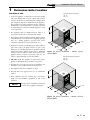
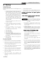
SBR-I-S Rev B
Installation & Service Manual
Models: 45,000 - 260,000 Btu/hr
WARNING:
This manual supplies information for the installation,
operation, and servicing of the appliance. It is strongly
recommended that this manual be reviewed completely
before proceeding with an installation. Perform steps in
the order given. Failure to comply could result in severe
personal injury, death, or substantial property damage.
Save this manual for future reference.
Contents
HAZARD DEFINITIONS . . . . . . . . . . . . . . . . . . . . . . . . . . 2
PLEASE READ BEFORE PROCEEDING . . . . . . . . . . . . 3-4
RATINGS . . . . . . . . . . . . . . . . . . . . . . . . . . . . . . . . . . . . . . 5
THE SOLUTION --HOW IT WORKS . . . . . . . . . . . . . . . . . . . 6-8
1. DETERMINE BOILER LOCATION
Location of Unit . . . . . . . . . . . . . . . . . . . . . . . . . . . . . . . . . 9
Clearances . . . . . . . . . . . . . . . . . . . . . . . . . . . . . . . . . . . . . 9
Combustion and Ventilation Air . . . . . . . . . . . . . . . . . . . 10-12
2. VENTING
A Conventional Negative Draft Venting System . . . . . . . 13-14
Vertical Vent Termination Clearances . . . . . . . . . . . . . . . 15
Masonry Chimney Installation . . . . . . . . . . . . . . . . . . . . . 16
Inspection of a Masonry Chimney . . . . . . . . . . . . . . . 16
Automatic Vent Damper . . . . . . . . . . . . . . . . . . . . . . . . . . 17
3. GAS CONNECTIONS
Gas Supply . . . . . . . . . . . . . . . . . . . . . . . . . . . . . . . . . . . 18
Gas Pressure Test . . . . . . . . . . . . . . . . . . . . . . . . . . . . . . 18
Gas Connection . . . . . . . . . . . . . . . . . . . . . . . . . . . . . . . . 18
Gas Piping . . . . . . . . . . . . . . . . . . . . . . . . . . . . . . . . . . . . 19
Gas Manifold Pressure Adjustment Procedure . . . . . . . . 20
Checking Gas Supply Pressure . . . . . . . . . . . . . . . . . . . 21
Combination Gas Valves . . . . . . . . . . . . . . . . . . . . . . . . . 22
4. WATER CONNECTIONS
Relief Valve . . . . . . . . . . . . . . . . . . . . . . . . . . . . . . . . . . . 23
Water Flow Switch (if equipped) . . . . . . . . . . . . . . . . . . . 23
Low Water Cutoff (if equipped) . . . . . . . . . . . . . . . . . . . . 24
Typical Heating Boiler Installations . . . . . . . . . . . . . . . . . 24-25
Piping of the Boiler System . . . . . . . . . . . . . . . . . . . . . . . 25
Performance Loop . . . . . . . . . . . . . . . . . . . . . . . . . . . . . . 27
Primary/Secondary Boiler Piping . . . . . . . . . . . . . . . . . . . 27-28
Low Temperature Bypass Requirements . . . . . . . . . . . . . 28
Boiler Flow Rates . . . . . . . . . . . . . . . . . . . . . . . . . . . . . . 28
Primary / Secondary Piping . . . . . . . . . . . . . . . . . . . . 29-31
Full System Flow . . . . . . . . . . . . . . . . . . . . . . . . . . . . 32-33
5. ELECTRICAL CONNECTIONS
Boiler Operating Temperature Control . . . . . . . . . . . . . . . 34
Room Thermostat or Remote Thermostat Connection . . 34
Auxiliary Device Connection to Terminal Strip . . . . . . . . . 34
Pump Wiring for a Heating Boiler . . . . . . . . . . . . . . . . . . 35
Temperature Adjustment . . . . . . . . . . . . . . . . . . . . . . . . . 35
Temperature Control Settings . . . . . . . . . . . . . . . . . . . . . 35
Maximum Set Point Determination . . . . . . . . . . . . . . . . . 36
Outdoor Air Reset Option . . . . . . . . . . . . . . . . . . . . . . . . 38
Additional Temperature Controls . . . . . . . . . . . . . . . . . . . 38
Blocked Vent and Flame Roll-Out / Flame Interlock Switch . 39
6. STARTUP
Initial Startup . . . . . . . . . . . . . . . . . . . . . . . . . . . . . . . . . . 40
Lighting Instructions for Spark Ignition Pilot Models (M9) . . . . 40
Safety Shutoff Test for Spark Ignition Pilot System . . . . . . 41
Intermittent Pilot Spark Ignition System (M9) . . . . . . . . . . . . 42
Freeze Protection . . . . . . . . . . . . . . . . . . . . . . . . . . . . . . . . . . . . . . 42
Water Treatment . . . . . . . . . . . . . . . . . . . . . . . . . . . . . . . . . . . . . . . . 42
7. MAINTENANCE
Maintenance and Annual Startup . . . . . . . . . . . . . . . . . . 43-48
8. TROUBLESHOOTING . . . . . . . . . . . . . . . . . . . . . . . . 49
9. DIAGRAMS . . . . . . . . . . . . . . . . . . . . . . . . . . . . . . . . . 50
Hazard definitions
The following defined terms are used throughout this manual to bring attention to the presence of hazards of various risk levels or
to important information concerning the life of the product.
DANGER
DANGER indicates an imminently hazardous situation which, if not avoided, will result in death or serious
injury.
WARNING WARNING indicates a potentially hazardous situation which, if not avoided, could result in death or serious
injury.
CAUTION indicates a potentially hazardous situation which, if not avoided, may result in minor or moderate
CAUTION injury.
CAUTION
CAUTION used without the safety alert symbol indicates a potentially hazardous situation which, if not
avoided, may result in property damage.
NOTICE
NOTICE indicates special instructions on installation, operation, or maintenance that are important but not
related to personal injury or property damage.
2
Installation & Service Manual
Please read before proceeding
NOTICE
This is a gas appliance and should be
installed by a licensed electrician and/or
certified gas supplier. Service must be
performed by a qualified service installer,
service agency or the gas supplier.
WARNING If the information in these instructions is
not followed exactly, a fire or explosion may
result causing property damage, personal
injury, or death.
This appliance MUST NOT be installed in
any location where gasoline or flammable
vapors are likely to be present, unless the
installation is such to eliminate the probable
ignition of gasoline or flammable vapors.
What to do if you smell gas –
• Do not try to light any appliance.
• Do not touch any electric switch; do not
use any phone in your building.
installation,
adjustment,
WARNING Improper
alteration, service or maintenance can result
in severe personal injury, death, or
substantial property damage. Refer to this
manual for assistance or additional
information, consult a qualified installer,
service agency or the gas supplier.
Checking equipment –
Upon receiving equipment, check for signs of shipping damage.
Pay particular attention to parts accompanying the appliances
which may show signs of being hit or otherwise being
mishandled. Verify total number of pieces shown on the
packing slip with those actually received. In case there is damage
or a shortage, immediately notify the carrier.
Do not use this appliance if any part has been under water.
The possible damage to a flooded appliance can be extensive
and present numerous safety hazards. Any appliance that has
been under water must be replaced.
Owner warning –
• Immediately call your gas supplier from a
near by phone. Follow the gas supplier’s
instructions.
NOTE: Retain this manual for future reference.
• If you cannot reach your gas supplier, call
the fire department.
The information contained in this manual is intended for use by
qualified professional installers, service technicians, or gas
suppliers. Consult your local expert for proper installation or
service procedures.
Installation and service must be performed
by a qualified installer, service agency, or the
gas supplier.
IMPORTANT
Warranty –
Installation and service must be performed by a qualified
service installer, service agency or the gas supplier.
Factory warranty (shipped with unit) does not apply to units
improperly installed or improperly operated.
Experience has shown that improper installation or system
design, rather than faulty equipment, is the cause of most
operating problems.
1.
Excessive water hardness causing a lime/scale build-up in
the copper tube is not the fault of the equipment and is
not covered under the manufacturer’s warranty (see
Water Treatment and Water Chemistry).
2.
Excessive pitting and erosion on the inside of the copper
tube may be caused by too much water velocity through
the tubes and is not covered by the manufacturer’s
warranty (see Boiler Flow Rates and Temperature Rise for
flow requirements).
Consult and follow all local Building and
Fire Regulations and other Safety Codes
that apply to this installation. Consult your
local gas utility company to authorize and
inspect all gas and flue connections.
Your conventionally vented gas appliance must have a supply of
fresh air circulating around it during burner operation for
proper gas combustion and proper venting.
WARNING
Should overheating occur or the gas supply
fail to shut off, do not turn off or disconnect
the electrical supply to the pump. Instead,
shut off the gas supply at a location external
to the appliance.
3
Installation & Service Manual
Please read before proceeding
WARNING
To minimize the possibility of serious
personal injury, fire, or damage to your
appliance, never violate the following safety
rules:
1. Boilers are heat producing appliances. To
avoid damage or injury, do not store
materials against the appliance or the
vent-air intake system. Use proper care
to avoid unnecessary contact (especially
children) with the appliance and vent-air
intake components.
2. Never cover your appliance, lean
anything against it, store trash or debris
near it, stand on it or in any way block
the flow of fresh air to your appliance.
3. UNDER NO CIRCUMSTANCES must
flammable materials such as gasoline or
paint thinner be used or stored in the
vicinity of this appliance, vent-air intake
system or any location from which fumes
could reach the appliance or vent-air
intake system.
Codes –
The equipment shall be installed in accordance with those
installation regulations in force in the local area where the
installation is to be made. These regulations shall be carefully
followed in all cases. Authorities having jurisdiction shall be
consulted before installations are made. In the absence of such
requirements, the installation shall conform to the latest edition
of the National Fuel Gas Code, ANSI Z223.1. Where required by
the authority having jurisdiction, the installation must conform
to American Society of Mechanical Engineers Safety Code for
Controls and Safety Devices for Automatically Fired Boilers,
ASME CSD-1. All boilers conform to the latest edition of the
ASME Boiler and Pressure Vessel Code, Section IV. Where
required by the authority having jurisdiction, the installation
must comply with the Canadian Association Code, CAN/CGAB149.1 and/or B149.2 and/or local codes.
This appliance meets the safe lighting performance criteria with
the gas manifold and control assembly provided as specified in
the ANSI standards for gas-fired appliances, ANSI Z21.13 and
ANSI Z21.10.3.
4
Installation & Service Manual
Ratings
Solution Boiler
I=B=R Rating
Input
MBH
Model Number
Note: Change “N” to
“L” for L.P. gas models.
Other Specifications
Gross
Output
MBH
Net
I=B=R
Ratings
Water,
MBH
(Note 1,5)
(Note 1,5)
(Note 4)
Boiler Water
Content
Gallons
Water
Connections
Vent
Gas
Connections
Size
Min
Max
CBN045
23
45
37
32
0.87
1 1/2"
1/2"
4"
CBN075
38
75
62
54
0.91
1 1/2"
1/2"
5"
CBN090
45
90
75
65
0.91
1 1/2"
1/2"
5"
CBN135
68
135
112
97
0.95
1 1/2"
1/2"
6"
CBN180
90
180
149
130
0.99
1 1/2"
3/4"
7"
CBN215
108
215
178
155
1.02
1 1/2"
3/4"
7"
CBN260
130
260
216
188
1.06
2"
3/4"
8"
NOTICE
(Note 3)
Maximum allowed working pressure is located on the rating plate.
Notes:
1. The ratings are based on standard test procedures
prescribed by the United States Department of Energy.
2. Net I=B=R ratings are based on net installed radiation of
sufficient quantity for the requirements of the building and
nothing need be added for normal piping and pickup.
Ratings are based on a piping and pickup allowance of 1.15.
UNIT EQUIPPED FOR
HIGH ALTITUDE
UP TO 2000 FT.
3. Use only the vent materials and methods specified in the
Installation and Service Manual.
4. The Solution is orificed for operation up to 2000 feet
altitude. The appliance will be derated 4% per 1000 feet
above 2000 feet elevation. Consult the factory for
installations above 2000 feet elevation.
Figure A High Altitude Label Location
5. Ratings have been confirmed by the Hydronics Institute,
Section of AHRI.
5
Installation & Service Manual
The Solution - How it works...
1.
Control panel cover
The control panel cover provides access to the thermostat, ignition
module, and transformer.
2.
Burner (not shown)
The burner is a cylindrical stainless steel tube used to regulate
burner flame.
3.
Drain port
Location from which the heat exchanger can be drained.
4.
Flue outlet
The flue outlet allows the connection of the vent pipe to the unit.
5.
Gas connection
The gas pipe connection on this appliance is 1/2", or 3/4" NPT. To
deliver the correct amount of gas volume to the appliance it may
be necessary to have a larger gas line reduced at the appliance.
Please reference the National Fuel Gas Code charts for more
details.
16. Sight Glass
The sight glass provides a view of the burner surface, burner flame,
and the pilot flame.
17. Temperature and pressure gauge
The temperature and pressure gauge monitors the outlet
temperature of the appliance as well as the system water
pressure.
18. Temperature sensor
This sensor monitors inlet water temperature. If selected as the
controlling sensor, the appliance will maintain the setpoint at this
sensor.
19. Terminal strip
The boiler is equipped with a terminal strip on the left side of the
unit to allow easy connection to contact points.
20. Top panel
Removable panel to gain access to the internal components.
6.
Gas valve
The gas valve allows the proper amount of gas to pass into the
burner for combustion.
7.
8.
Heat exchanger
The thermostat monitors the water temperature via a temperature
sensor and will initiate a call for heat when the water temperature
drops below the setpoint plus the differential on the thermostat.
The heat exchanger allows system water to flow through specially
designed tubes for maximum heat transfer. The glass lined
headers and copper finned tubing are encased in a jacket that
contains the combustion process.
22. Transformer
High limit sensor
23. Water inlet (system return)
Device that monitors the outlet water temperature to ensure
safe operation. If the temperature exceeds its setting, it will break
the control circuit, shutting the appliance down.
9.
21. Thermostat
Ignition module
The ignition module responds to a call for heat signal to provide
burner operation.
10. Junction box
The junction box contains the connection points for the line
voltage power and all pumps.
11. Performance loop
A pumped bypass provides constant flow through the heat
exchanger when the building system flow is reduced.
12. Performance Loop Pump
The pump ensures adequate flow to operate the unit.
13. Pilot (not shown)
The pilot is a spark ignition device used to light a pilot flame which
in turn is used to light the main burners.
14. Pump relay
The pump relay energizes the pump on a call for heat.
15. Relief valve
The relief valve is a safety device that ensures the maximum
pressure of the appliance is not exceeded.
6
The transformer reduces 120 VAC supply voltage to 24 VAC for the
control circuit.
The water inlet is a 1 1/2" pipe connection that receives water
from the system and delivers it to the heat exchanger.
24. Water outlet (system supply)
The water outlet is a 1 1/2" pipe connection that supplies
water to the system with connections for a flow switch, a relief
valve, and a temperature and pressure gauge.
25. Gas manifold pipe
Delivers gas from the gas valve to the main burners through a
number of orifices.
Installation & Service Manual
The Solution - How it works...
(continued)
4
10
20
17
15
1
8
3
5
19
Models 45,000 - 90,000 Btu/hr Front View
Models 45,000 - 90,000 Rear View
7
22
18
21
12
9
6
11
23
25
24
14
16
Models 45,000 - 90,000 Right Side (inside unit)
Models 45,000 - 90,000 Left Side (inside unit)
7
Installation & Service Manual
The Solution - How it works...
10
4
20
17
15
1
8
3
19
5
Models 135,000 - 260,000 Btu/hr Front View
Models 135,000 - 260,000 Btu/hr Rear View
7
9
18
12
3
6
3
11
21
25
23
24
22
14
Models 135,000 - 260,000 Btu/hr Right Side (inside unit)
8
Models 135,000 - 260,000 Btu/hr Left Side (inside unit)
Installation & Service Manual
1
Determine boiler location
Location of unit
1. Locate the appliance so that if water connections should
leak, water damage will not occur. When such locations
cannot be avoided, it is recommended that a suitable drain
pan, adequately drained, be installed under the appliance.
The pan must not restrict combustion air flow. Under no
circumstances is the manufacturer to be held responsible
for water damage in connection with this appliance, or any
of its components.
2. The appliance must be installed indoors where it is
protected from exposure to wind, rain and weather.
Recommended Service Clearances:
Left - 24”
Front - 24”
14"
TOP
3. The appliance must be installed so that the ignition system
components are protected from water (dripping, spraying,
rain, etc.,) during appliance operation and service
(circulator replacement, control replacement, etc.,).
6 " RIGHT
6 " REAR
4. Appliances located in a residential garage and in adjacent
spaces that open to the garage and are not part of the
living space of a dwelling unit must be installed so that all
burners and burner ignition devices have a minimum
clearance of not less than 18" (46cm) above the floor. The
appliance must be located or protected so that it is not
subject to physical damage by a moving vehicle.
18 "
LEFT
18 "
FRONT
Figure 1-1_Alcove Installation - Models 45,000 180,000 Btu/hr
Recommended Service Clearances:
Left - 24”
Front - 24”
5. DO NOT install this appliance in any location where
gasoline or flammable vapors are likely to be present.
6. All units have been approved for alcove installation (an
ALCOVE is a closet enclosure without a front door).
7. The appliance must not be installed on carpet.
8. All units have been approved for use on combustible
surfaces.
29"
TOP
9. Allow sufficient space for servicing pipe connections,
pump and other auxiliary equipment, as well as the
appliance.
NOTICE
Clearances from combustible construction
are noted on the appliance rating plate.
6 " RIGHT
6 " REAR
18 "
FRONT
18 "
LEFT
Figure 1-2_Alcove Installation - Models 215,000 260,000 Btu/hr
9
Installation & Service Manual
1
Determine boiler location
Combustion
and
ventilation
air
requirements for conventionally vented
appliances
Provisions for combustion and ventilation air must be in
accordance with, Air for Combustion and Ventilation, of the
latest edition of the National Fuel Gas Code, ANSI Z223.1, in
Canada, the latest edition of CGA Standard B149 Installation
Code for Gas Burning Appliances and Equipment, or
applicable provisions of the local building codes.
The room where the appliance is installed MUST be provided
with properly sized openings to assure adequate combustion
air and proper ventilation when the appliance is installed with
conventional venting.
Figure 1-4_Combustion Air Through Ducts
2.
If combustion and ventilation air is taken from the
outdoors using a duct to deliver the air to the room where
the appliance is installed, each of the two openings should
be sized based on a minimum free area of one square inch
per 2000 Btu/hr (11cm2 per kW) (see FIG. 1-4).
Figure 1-3_Combustion Air Direct from Outside
1.
If air is taken directly from outside the building
with no duct, provide two permanent openings (see
FIG. 1-3):
(a) Combustion air opening, with a minimum free
area of one square inch per 4000 Btu/hr input
(5.5 cm2 per kW). This opening must be
located within 12" (30 cm) of the floor.
(b) Ventilation air opening, with a minimum free
area of one square inch per 4000 Btu/hr input
(5.5 cm2 per kW).
This opening must be
located within 12" (30 cm) of the ceiling.
10
Figure 1-5_Combustion Air from Interior Space
3.
If air is taken from another interior space that is adequately
ventilated, each of the two openings specified above should
have a net free area of one square inch for each 1000 Btu/hr
(22cm2 per kW) of input, but not less than 100 square
inches (645cm2) (see FIG. 1-5).
Installation & Service Manual
1
Determine boiler location
(continued)
CAUTION
Figure 1-6_Combustion Air from Outside Single Opening
4.
If a single combustion air opening is provided to bring
combustion air in directly from the outdoors, the
opening must be sized based on a minimum free area of
one square inch per 3000 Btu/hr (7 cm2 per kW). This
opening must be located within 12" (30 cm) of the top of
the enclosure (see FIG. 1-6).
Combustion air requirements are based on the latest edition
of the National Fuel Gas Code, ANSI Z223.1, in Canada refer
to National Standard CAN B149.1. Check all local code
requirements for combustion air.
All dimensions are based on net free area in square inches.
Metal louvers or screens reduce the free area of a combustion
air opening a minimum of approximately 25%. Check with
louver manufacturers for exact net free area of louvers. Where
two openings are provided, one must be within 12" (30 cm) of
the ceiling and one must be within 12" (30 cm) of the floor of
the room where the appliance is installed. Each opening must
have a net free area as specified in Table 1B (on page 12).
Single openings shall be located within 12" (30 cm) of the
ceiling.
Under no circumstances should the room
where the appliance is installed ever be
under a negative pressure. Particular care
should be taken where exhaust fans, attic
fans, clothes dryers, compressors, air
handling units, etc., may take away air from
the appliance.
The combustion air supply must be completely free of any
flammable vapors that may ignite or chemical fumes which may
be corrosive to the appliance. Common corrosive chemical
fumes which must be avoided are fluorocarbons and other
halogenated compounds, most commonly present as
refrigerants or solvents, such as freon, tricholorethylene,
perchlorethylene, chlorine, etc. These chemicals, when burned,
form acids which quickly attack the heat exchanger finned tubes,
headers, flue collectors, and the vent system. The result is
improper combustion and a non-warrantable, premature
appliance failure.
The result is improper combustion and a non-warrantable,
premature appliance failure.
EXHAUST FANS: Any fan or equipment which exhausts air
from the equipment room may deplete the combustion air
supply and/or cause a downdraft in the venting system. Spillage
of flue products from the venting system into an occupied living
space can cause a very hazardous condition that must be
immediately corrected. If a fan is used to supply combustion air
to the equipment room, the installer must make sure that it does
not cause drafts which could lead to nuisance operational
problems with the appliance.
11
Installation & Service Manual
1
Determine boiler location
TABLE - 1B
MINIMUM RECOMMENDED COMBUSTION
AIR SUPPLY TO EQUIPMENT ROOM
Input
Btu/hr
*Outside Air from
2 Openings Directly from
Outdoors
Top
Opening, in2
Bottom
Opening, in2
45,000
12
(78 cm2)
12
(78 cm2)
75,000
19
(123 cm2)
90,000
*Outside Air from
1 Opening Directly
from Outdoors, in2
*Outside Air from
2 Ducts Delivered from
Outdoors
**Inside Air from
2 Ducts Delivered from
Interior Space
Top
Opening, in2
Bottom
Opening, in2
Top
Opening, in2
Bottom
Opening, in2
15
(97 cm2)
23
(149 cm2)
23
(149 cm2)
100
(646 cm2)
100
(646 cm2)
19
(123 cm2)
25
(162 cm2)
38
(246 cm2)
38
(246 cm2)
100
(646 cm2)
100
(646 cm2)
23
(148 cm2)
23
(148 cm2)
30
(194 cm2)
45
(291 cm2)
45
(291 cm2)
100
(646 cm2)
100
(646 cm2)
135,000
34
(220 cm2)
34
(220 cm2)
45
(291 cm2)
68
(439 cm2)
68
(439 cm2)
135
(871 cm2)
135
(871 cm2)
180,000
45
(291 cm2)
45
(291 cm2)
60
(388 cm2)
90
(581 cm2)
90
(581 cm2)
180
(1,162 cm2)
180
(1,162 cm2)
215,000
54
(349 cm2)
54
(349 cm2)
72
(465 cm2)
108
(697 cm2)
108
(697 cm2)
215
(1,388 cm2)
215
(1,388 cm2)
260,000
65
(420 cm2)
65
(420 cm2)
87
(562 cm2)
130
(839 cm2)
130
(839 cm2)
260
(1,678 cm2)
260
(1,678 cm2)
*Outside air openings shall directly communicate with the outdoors. When combustion air is drawn from the outside through a
duct, the net free area of each of the two openings must have twice (2 times) the free area required for Outside Air/2 Openings.
The above requirements are for the boiler only; additional gas fired appliances in the equipment room will require an increase in
the net free area to supply adequate combustion air for all appliances.
**Combined interior space must be 50 cubic feet per 1,000 Btu/hr input. Buildings MUST NOT be of *“Tight Construction”.
For buildings of *“Tight Construction”, provide air openings into the building from outside.
*No combustion air openings are needed when the water heater is installed in a space with a volume NO LESS than 50 cubic feet
per 1,000 Btu/hr of all installed gas fired appliances. Buildings MUST NOT be of *“Tight Construction”.
*”Tight Construction” is defined as a building with less than 0.40 ACH (air changes per hour).
Vent installations for connection to gas vents or
chimneys must be in accordance with “Venting of
Equipment,” of the latest edition of the National Fuel Gas
Code, ANSI Z223.1, in Canada, the latest edition of CGA
Standard B149 Installation Code for Gas Burning Appliances
and Equipment or applicable provisions of the local building
codes.
Adequate combustion and ventilation air must be
supplied to the room where the appliance is installed in
accordance with the latest edition of the National Fuel Gas
Code, ANSI Z223.1, in Canada, the latest edition of CGA
Standard B149 Installation Code for Gas Burning Appliances
and Equipment, or applicable provisions of the local building
codes.
12
The distance of the vent terminal from adjacent
buildings, windows that open and building openings MUST
comply with the latest edition of the National Fuel Gas Code,
ANSI Z223.1, in Canada, the latest edition of CGA Standard
B149 Installation Code for Gas Burning Appliances and Equipment.
Vent connection is made directly to the top of the
appliance. This appliance is designed with a built-in draft
diverter. No additional external draft hood is required. The
connection from the appliance vent to the common vent or
chimney must be made as direct as possible.
Installation & Service Manual
2
Venting
A Conventional Negative Draft
Venting System
The negative draft in a conventional vent installation must be
within the range of a negative 0.02 to 0.05 inches water
column to ensure proper operation. All draft readings are
made while the appliance is in stable operation
(approximately 2 to 5 minutes).
Multiple appliance installations with combined venting or
common venting with other negative draft appliances require
that each appliance must have draft within the proper range.
If the draft measured above the appliance’s built-in draft
diverter exceeds the specified range in a dedicated chimney
for a single appliance installation or in combined venting with
other negative draft appliances, a barometric damper must be
installed to control draft.
TABLE - 2A
VENT PIPE SIZES
Input Btu/hr
Flue Size
45,000
4"
75,000
5"
90,000
5"
135,000
6"
180,000
7"
215,000
7"
260,000
8"
On a conventionally vented, negative draft appliance, the
connection from the vent to the chimney or vent termination
on the outside of the building MUST be made with listed Type
“B” double wall (or equivalent) vent connectors and must be
direct as possible with no reduction in diameter. Use the
National Fuel Gas Code venting tables for double wall vent to
properly size all vent connectors and stacks. The Type “B” vent
and accessories, such as firestop spacers, thimbles, caps, etc.,
MUST be installed in accordance with the manufacturer’s
listing. The vent connector and firestop must provide correct
spacing to combustible surfaces and seal to the vent connector
on the upper and lower sides of each floor or ceiling through
which the vent connector passes.
Any vent materials used must be listed by a nationally
Figure 2-1_Conventional Negative Draft Vertical Venting recognized test agency for use as vent material.
13
Installation & Service Manual
2
Venting
Locate appliance as close as possible to a chimney or gas vent.
Avoid long horizontal runs of the vent pipe, 90° elbows,
reductions and restrictions. Horizontal portions of the
venting system shall be supported to prevent sagging.
Horizontal runs must slope upwards not less than 1/4 inch
per foot (21 mm/m) from the appliance to the vent terminal.
Follow manufacturer’s instructions.
Do not use an existing chimney as a raceway for a flue pipe if
another appliance or fireplace is vented through the chimney.
The weight of the venting system must not rest on the
appliance. Adequate support of the venting system must be
provided in compliance with local codes and other applicable
codes. All connections should be secured with rustproof
sheet metal screws.
Vent connectors serving appliances vented by natural draft
shall not be connected to any portion of a
mechanical draft system operating under positive
pressure. Connection to a positive pressure chimney may
cause flue products to be discharged into the living space
causing serious health injury.
Common venting systems may be too large when an existing
appliance is removed. At the time of removal of an existing
appliance, the following steps shall be followed with each
appliance remaining connected to the common venting
system placed in operation, while other appliances remaining
connected to the common venting system are not in
operation.
(a) Seal any unused opening in the common venting
system.
(b) Visually inspect the venting system for proper size
and horizontal pitch and determine there is no
blockage or restriction, leakage, corrosion and other
deficiencies which could cause an unsafe condition.
(c) Insofar as is practical, close all building doors and
windows and all doors between the space in which
the appliances remaining connected to the common
venting system are located and other spaces of the
building. Turn on clothes dryers and any other
appliances not connected to the common venting
system. Turn on any exhaust fans, such as range
hoods and bathroom exhausts, so they will operate
at maximum speed. Do not operate a summer
exhaust fan. Close fireplace dampers.
(d) Place in operation the appliance being inspected.
Follow the lighting instructions. Adjust thermostat
so appliance will operate continuously.
14
(e) Test for spillage at the draft hood/relief opening after 5
minutes of main burner operation. Use the flame of a
match or candle, or smoke from a cigarette, cigar or
pipe.
(f) After it has been determined that each appliance
remaining connected to the common venting system
properly vents when tested as outlined above, return
doors, windows, exhaust fans, fireplace dampers and
other gas burning appliances to their previous
conditions of use.
(g) Any improper operation of the common venting
system should be corrected so that the installation
conforms to the latest edition of the National Fuel Gas
Code, ANSI Z223.1. In Canada, the latest edition of
CGA Standard B149 Installation Code for Gas Burning
Appliances
and
Equipment.
When resizing any portion of the common venting
system, the common venting system should be resized
to approach the minimum size as determined using the
appropriate tables in Part 11 in the latest edition of the
National Fuel Gas Code, ANSI Z223.1. In Canada, the
latest edition of CGA Standard B149 Installation Code
for Gas Burning Appliances and Equipment.
Installation & Service Manual
2
Venting
(continued)
Vertical Vent Termination Clearances
10' OR LESS
10' OR LESS
10' OR LESS
CHIMNEY
2' MIN
2' MIN
3' MIN
2' MIN
3' MIN
RIDGE
CHIMMEY
Figure 2-2_Vent Termination from Peaked Roof 10' or
Less from Ridge
WALL OR
PARAPET
CHIMMEY
Figure 2-4_Vent Termination from Flat Roof 10' or Less
from Parapet Wall
10' OR MORE
MORE THAN 10'
3'
10'
2' MIN
CHIMNEY
RIDGE
3' MIN
NOTE:
NO HEIGHT ABOVE
PARAPET REQUIRED
WHEN DISTANCE
FROM WALLS OR
PARAPETS IS MORE
THAN 10'.
WALL OR
PARAPET
CHIMNEY
Figure 2-3_Vent Termination from Peaked Roof More
than 10' from Ridge
Figure 2-5_Vent Termination from Flat Roof More Than
10' from Parapet Wall
T