1
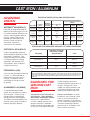
WELDIRECTORY
CAST IRON AND ALUMINUM ARC WELDING ELECTRODES
Softweld ®, Ferroweld® and Aluminweld®
CAST IRON / ALUMINUM
ADVANTAGE
LINCOLN
SOFTWELD® 55 Ni (ENiFe-CI)
A versatile, all-purpose electrode for
repairing and reclaiming gray cast iron.
It is recommended for repairing heavy
sections and phosphorous bearing
castings. Welds made with this
electrode are strong and ductile.
Multi-pass welds are typically
machinable. Operational
characteristics are excellent.
ELECTRODE IDENTIFICATION AND OPERATING DATA
Sizes and Current Ranges
(Amps)
Marking
Printed on Electrode Polar- 3/32” Size 1/8” Size 5/32” Size
Coating
(2.5mm) (3.2mm)
(4.0mm)
ity
Electrode
Coating
Color
Ferroweld
Black
St
DC(+); AC
--
80-120
---
Softweld
55 Ni
Black
NiFe-CI
DC(+)
AC
40-65
50-65
70-95
80-95
100-135
110-135
Softweld
99 Ni
Black
Ni-CI
DC(+)
AC
50-80
50-80
80-110
85-120
100-140
110-150
Aluminweld
43
White
None
DC(+)
---
85-135
110-165
ELECTRODE CONFORMANCES, APPROVALS & TYPICAL PROPERTIES
SOFTWELD® 99 Ni (ENi-CI)
A high nickel electrode specifically
recommended for applications where
machinability is important. Even
single pass welds are machinable.
It is recommended for surfacing
applications and repairing small
casting defects when the deposit
will require machining.
Electrode
Conforms to Test Requirements of AWS
Specifications
Class
Ferroweld
A5.15
ESt
Softweld 55 Ni
A5.15
ENiFe-CI
Softweld 99 Ni
A5.15
ENi-CI
Aluminweld 43
A5.3
E4043
FERROWELD® (ESt)
A low cost steel electrode for repairing
cast iron. It is recommended for
repairing pits and small cracks in
castings. The deposits are not
machinable but may be finished
by grinding.
ALUMINWELD® 43 (E4043)
An extruded electrode for both
metallic arc and carbon arc welding
aluminum plate. The dense high
strength welds can be polished
leaving practically no discoloration.
The molten flux retards oxidation and
dissolves excess aluminum oxide to
produce high quality deposits.
The serviceability of a product or structure utilizing this type of information is and must be the sole responsibility of the builder/user. Many variables beyond the control of The Lincoln Electric Company affect the
results obtained in applying this type of information. These variables include, but are not limited to, welding procedure, plate chemistry and temperature, weldment design, fabrication methods and service requirements.
GUIDELINES FOR
WELDING CAST
IRON
ing after welding to restore the
strength and ductility requirements to
the part. Although they can be
welded, the special procedures and
heat treating required makes repair
welding these materials expensive.
The majority of cast iron parts are
gray cast iron. These guidelines
are limited to welding this material.
Because of its hard and brittle
structure, welding white cast iron is
generally impractical. Malleable,
nodular, and other heat treated types
of cast iron usually require heat treat-
How to Locate Cracks - A simple
but effective way of locating surface
cracks is to use commercial dye
penetrant methods. As an alternate,
you can swab the damaged area with
a kerosene soaked rag to remove
grease and dust. Immediately chalk
over the area with common
GUIDELINES FOR
WELDING CAST
IRON (CONT.)
blackboard chalk. After a few
minutes, even cracks not visible to the
naked eye are evident because the
kerosene from the cracks bleeds back
through the chalk.
Preparation for Welding - For weld
soundness, the cracks must be
properly prepared before welding. Drill
a hole at the end of each crack to
prevent it from extending further.
Grind, chip, machine or saw the crack
to create a bevel. Gas cutting or arc
gouging can be used on castings that
are preheated for welding. Be sure to
get to the bottom of the crack. On
sections more than 3/16” (4.8mm)
thick, bevel the edges so the root of
the joint is 1/8” (3.2mm) to 3/16”
(4.8mm) wide. If the crack extends
through the section, leave about a
1/8” (3.2mm) gap and 1/16” (1.6mm)
land.
1/16”
1/8”
Remove surface scale by grinding
wherever welds are to be placed.
Be sure the work is clean and dry.
Preheating drives moisture and oil
out of the casting.
Types of Electrodes to Use - For
machinable welds, use Softweld 99
Ni or Softweld 55 Ni. However, the
fusion line between Softweld deposits
and the cast iron may be too hard
to machine unless the casting is
preheated over 500°F. Ferroweld
deposits are not machinable.
Welding Techniques with
Preheating - Although the welding
of gray cast iron has been made to
sound “mysterious”, it can be readily
done if a few facts about the metal
and how it is made are understood.
Most of the difficulty is caused by the
high carbon content in cast iron usually between 2% and 4% carbon.
This fact, plus an understanding of
how cast iron is made, indicates the
heating-cooling cycles needed for
successful welding.
A gray iron casting is made by pouring
molten iron into a mold. It is allowed
to cool slowly. As it cools, the carbon
in the metal becomes a flaky form of
graphite. This graphite gives the iron
its characteristic gray color and some
of its properties.
When it is welded, part of the gray iron
is melted and an area adjacent to the
weld is raised above a temperature
called a critical temperature - about
1450°F. The mass of the casting
around the weld tends to draw the
heat from the weld area rapidly. If this
cooling of the heat-affected zone and
the weld is more rapid than it was
when the casting was originally made,
a highly brittle, crack-sensitive area
forms.
The best method to slow the cooling
rate is to preheat the casting to
prevent the iron from rapidly
absorbing heat from the weld area.
This requires a preheat temperature
between 500° and 1200°F. Do not
preheat over 1400°. Preheat
temperature can easily be determined
by using special heat indicating
crayons.
Preheat the entire casting slowly and
uniformly. Do not attempt to preheat
only the area to be welded.
Always use low currents for minimum
penetration and low ad-mixture. Weld
with short 3” (76.2mm) to 5” (127mm)
beads. Immediately after welding,
peen each bead to relieve stresses.
Be sure the preheat temperature is
maintained until the entire welding job
is completed. After welding, allow the
casting to cool slowly to room
temperature overnight just as it did
when it was originally made. To do
this, furnace cool or cover the casting
with dry sand, powdered lime, or a
fireproof blanket. This will produce a
strong, ductile deposit and fusion zone
which is relatively free of cracks.
Welding Techniques without
Preheat - Because of the size or other
problems, preheating the casting is
often impractical or impossible. In
such cases, the cracks can still be
repaired. Prepare the crack for
welding with the same methods
described previously.
When heat is applied suddenly to
glass, it cracks. In this way, cast iron
resembles glass. Cast iron should
never be welded cold.
When the high preheat temperatures
cannot be applied, heat the casting to
about 100°F. Do not try to weld
outdoors in cold weather. If the part
being welded is an engine block or
head, a uniform preheat can be
obtained by running the engine, if
possible, for a few minutes. Never
heat the casting so hot that you
cannot place your bare hand on it.
Make very short beads - not over
1” (25.4mm) long. Immediately peen
each bead while it is hot to relieve
shrinkage stresses and retard
cracking. While one bead is cooling,
deposit others at scattered points
throughout the joint. All weld craters
must be filled. Whenever possible,
this is done by ending a bead by
blending its crater into the start of a
previously deposited bead. All beads
should be deposited in the same
direction. Ends of adjacent parallel
beads should not line up with each
other.
4
6
2
3
5
1
Let each bead cool to the point where
it can be touched with a bare hand
before starting an adjacent bead.
Sealing Cracks - Because of the
nature of cast iron, tiny cracks tend to
appear next to the weld even when
GUIDELINES FOR
WELDING CAST
IRON (CONT.)
ALUMINUM ARC
WELDING
ELECTRODES
Hold the electrode almost
perpendicular to the work at all times
to obtain even melt-off of the flux.
Point the arc directly into the joint so
both edges are properly and
uniformly heated.
good procedures are followed. If the
casting must be water tight, this can
be a problem. However, leaking can
usually be eliminated with some sort
of sealing compound or they may rust
shut very soon after being returned to
service.
PROCEDURES - USE ELECTRODE
POSITIVE (DC+)
For tacking, use currents about 20%
above the maximum current listed in
the recommended ranges. Use a
short arc with a rotary motion.
The Studding Method - One method
used to repair major breaks in large
castings is to drill and tap holes over
the beveled surface area. Screw
studs into the holes leaving 3/16”
(4.8mm) to 1/4” (6.4mm) of the stud
above the surface. Then, using the
standard methods and electrodes
described here, weld the studs in
place and cover the entire surface of
the break with weld deposit. Once a
good weld deposit layer is made, the
two sides of the crack can be welded
together with more conventional
methods. However, overheating the
casting area must still be avoided.
In cases of severe damage, use of
mild steel plates sometimes produces
good results. To do this, cut out the
damaged area. Fit a piece of mild
steel of the appropriate size in the
damaged area and weld the steel to
the cast iron. Use the welding
methods and electrodes used to
weld cast iron to cast iron.
Hold a short arc with the coating
almost touching the molten pool.
Use the highest current possible
without melting the edges back
too far or burning through.
The high melting rate of the aluminum
electrode combined with the high
conductivity of the aluminum plate
chills the weld rapidly. Therefore, to
keep the pool molten long enough to
form well-shaped beads preheating to
600-700°F is often needed.
Remove the last traces of slag with
warm water and a wire brush or by
soaking the weld in a 5% nitric acid or
10% warm sulfuric acid solution
followed by a warm water rinse.
WARNING: Be careful with these
strong acid solutions. Wear
safety glasses and avoid contact
with skin or clothing.
Avoid out-of-position welding.
Strike the electrode by “scratching”.
Strike the arc in the crater of the
previous bead, then quickly move
back along the weld for 1/2”
(12.7mm) and proceed as usual. Be
sure the crater is completely remelted.
Aluminweld can also be used as a
filler rod with a carbon arc torch.
¢¢QQQQ
¢¢¢¢
QQQQQ
¢¢¢
¢Q¢Q
¢¢¢¢
QQQQ
¢¢¢¢¢
¢QQQQQQ
Q
¢
Q
¢
Q
¢
¢Q¢QQQQ
¢¢¢
¢Q¢Q
Customer Assistance Policy
The business of The Lincoln Electric Company is manufacturing and selling high quality welding equipment, consumables, and cutting equipment. Our challenge is to meet the needs of
our customers and to exceed their expectations. On occasion, purchasers may ask Lincoln Electric for advice or information about their use of our products. We respond to our customers
based on the best information in our possession at that time. Lincoln Electric is not in a position to warrant or guarantee such advice, and assumes no liability, with respect to such
information or advice. We expressly disclaim any warranty of any kind, including any warranty of fitness for any customer’s particular purpose, with respect to such information or advice. As
a matter of practical consideration, we also cannot assume any responsibility for updating or correcting any such information or advice once it has been given, nor does the provision of information or advice create, expand or alter any warranty with respect to the sale of our products.
Lincoln Electric is a responsive manufacturer, but the selection and use of specific products sold by Lincoln Electric is solely within the control of, and remains the sole responsibility of the
customer. Many variables beyond the control of Lincoln Electric affect the results obtained in applying these type of fabrication methods and service requirements.
DISTRIBUTED BY:
THE
LINCOLN ELECTRIC
COMPANY
Local Sales and Service through Global
Subsidiaries and Distributors
Cleveland, Ohio 44117-1199 U.S.A
TEL: 216.481.8100
FAX: 216.486.1751
WEB SITE: www.lincolnelectric.com
Cast Iron/Non-Ferrous
C8.10 6/99
web update 5/08


![[ TVS M ASCOT USER M ANUAL ] - TVS-E](http://vs1.manualzilla.com/store/data/005862685_1-4bbb7317613bf954ee62497b52c82516-150x150.png)