1
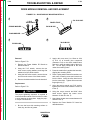
View Safety Info
SVM150-A
September, 2002
TM
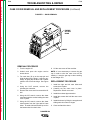
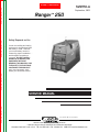
Ranger 250
For use with machines having Code Numbers: 10654
Return to Master TOC
View Safety Info
View Safety Info
Safety Depends on You
Return to Master TOC
Return to Master TOC
RETURN TO MAIN INDEX
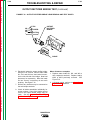
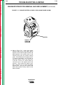
Lincoln arc welding and cutting
equipment is designed and built
with safety in mind. However,
your overall safety can be increased by proper installation . . .
and thoughtful operation on
your part. DO NOT INSTALL,
OPERATE OR REPAIR THIS
EQUIPMENT WITHOUT
READING THIS MANUAL AND
THE SAFETY PRECAUTIONS
CONTAINED THROUGHOUT.
And, most importantly, think
before you act and be careful.
View Safety Info
Return to Master TOC
SERVICE MANUAL
Copyright © 2002 Lincoln Global Inc.
• World's Leader in Welding and Cutting Products •
• Sales and Service through Subsidiaries and Distributors Worldwide •
Cleveland, Ohio 44117-1199 U.S.A. TEL: 216.481.8100 FAX: 216.486.1751 WEB SITE: www.lincolnelectric.com
Return to Master TOC
i
i
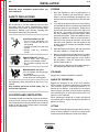
SAFETY
WARNING
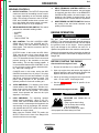
CALIFORNIA PROPOSITION 65 WARNINGS
Diesel engine exhaust and some of its constituents
are known to the State of California to cause cancer, birth defects, and other reproductive harm.
The Above For Diesel Engines
The engine exhaust from this product contains
chemicals known to the State of California to cause
cancer, birth defects, or other reproductive harm.
The Above For Gasoline Engines
ARC WELDING CAN BE HAZARDOUS. PROTECT YOURSELF AND OTHERS FROM POSSIBLE SERIOUS INJURY OR DEATH.
KEEP CHILDREN AWAY. PACEMAKER WEARERS SHOULD CONSULT WITH THEIR DOCTOR BEFORE OPERATING.
Return to Master TOC
Return to Master TOC
Read and understand the following safety highlights. For additional safety information, it is strongly recommended that you
purchase a copy of “Safety in Welding & Cutting - ANSI Standard Z49.1” from the American Welding Society, P.O. Box 351040,
Miami, Florida 33135 or CSA Standard W117.2-1974. A Free copy of “Arc Welding Safety” booklet E205 is available from the
Lincoln Electric Company, 22801 St. Clair Avenue, Cleveland, Ohio 44117-1199.
BE SURE THAT ALL INSTALLATION, OPERATION, MAINTENANCE AND REPAIR PROCEDURES ARE
PERFORMED ONLY BY QUALIFIED INDIVIDUALS.
FOR ENGINE
powered equipment.
1.h. To avoid scalding, do not remove the
radiator pressure cap when the engine is
hot.
1.a. Turn the engine off before troubleshooting and maintenance
work unless the maintenance work requires it to be running.
____________________________________________________
1.b.Operate engines in open, well-ventilated
areas or vent the engine exhaust fumes
outdoors.
____________________________________________________
1.c. Do not add the fuel near an open flame welding arc or when the engine is running. Stop
the engine and allow it to cool before refueling to prevent spilled fuel from vaporizing on
contact with hot engine parts and igniting. Do
not spill fuel when filling tank. If fuel is spilled,
wipe it up and do not start engine until fumes
have been eliminated.
____________________________________________________
1.d. Keep all equipment safety guards, covers
and devices in position and in good
repair.Keep hands, hair, clothing and tools
away from V-belts, gears, fans and all other
moving parts when starting, operating or
repairing equipment.
Return to Master TOC
____________________________________________________
ELECTRIC AND
MAGNETIC FIELDS
may be dangerous
2.a. Electric current flowing through any conductor causes
localized Electric and Magnetic Fields (EMF). Welding
current creates EMF fields around welding cables and
welding machines
2.b. EMF fields may interfere with some pacemakers, and
welders having a pacemaker should consult their physician
before welding.
2.c. Exposure to EMF fields in welding may have other health
effects which are now not known.
2.d. All welders should use the following procedures in order to
minimize exposure to EMF fields from the welding circuit:
2.d.1. Route the electrode and work cables together - Secure
them with tape when possible.
1.e. In some cases it may be necessary to remove safety
guards to perform required maintenance. Remove
guards only when necessary and replace them when the
maintenance requiring their removal is complete.
Always use the greatest care when working near moving
parts.
___________________________________________________
1.f. Do not put your hands near the engine fan. Do not attempt to
override the governor or idler by pushing on the throttle control rods while the engine is running.
___________________________________________________
1.g. To prevent accidentally starting gasoline engines while
turning the engine or welding generator during maintenance
work, disconnect the spark plug wires, distributor cap or
magneto wire as appropriate.
2.d.2. Never coil the electrode lead around your body.
2.d.3. Do not place your body between the electrode and
work cables. If the electrode cable is on your right
side, the work cable should also be on your right side.
2.d.4. Connect the work cable to the workpiece as close as
possible to the area being welded.
2.d.5. Do not work next to welding power source.
Mar ‘95
RANGER 250
Return to Master TOC
Return to Master TOC
ii
SAFETY
ELECTRIC SHOCK can kill.
ARC RAYS can burn.
3.a. The electrode and work (or ground) circuits
are electrically “hot” when the welder is on.
Do not touch these “hot” parts with your bare
skin or wet clothing. Wear dry, hole-free
gloves to insulate hands.
4.a. Use a shield with the proper filter and cover
plates to protect your eyes from sparks and
the rays of the arc when welding or observing
open arc welding. Headshield and filter lens
should conform to ANSI Z87. I standards.
3.b. Insulate yourself from work and ground using dry insulation.
Make certain the insulation is large enough to cover your full
area of physical contact with work and ground.
4.b. Use suitable clothing made from durable flame-resistant
material to protect your skin and that of your helpers from
the arc rays.
In addition to the normal safety precautions, if welding
must be performed under electrically hazardous
conditions (in damp locations or while wearing wet
clothing; on metal structures such as floors, gratings or
scaffolds; when in cramped positions such as sitting,
kneeling or lying, if there is a high risk of unavoidable or
accidental contact with the workpiece or ground) use
the following equipment:
• Semiautomatic DC Constant Voltage (Wire) Welder.
• DC Manual (Stick) Welder.
• AC Welder with Reduced Voltage Control.
4.c. Protect other nearby personnel with suitable, non-flammable
screening and/or warn them not to watch the arc nor expose
themselves to the arc rays or to hot spatter or metal.
3.c. In semiautomatic or automatic wire welding, the electrode,
electrode reel, welding head, nozzle or semiautomatic
welding gun are also electrically “hot”.
3.d. Always be sure the work cable makes a good electrical
connection with the metal being welded. The connection
should be as close as possible to the area being welded.
3.e. Ground the work or metal to be welded to a good electrical
(earth) ground.
3.f. Maintain the electrode holder, work clamp, welding cable and
welding machine in good, safe operating condition. Replace
damaged insulation.
Return to Master TOC
ii
3.g. Never dip the electrode in water for cooling.
3.h. Never simultaneously touch electrically “hot” parts of
electrode holders connected to two welders because voltage
between the two can be the total of the open circuit voltage
of both welders.
3.i. When working above floor level, use a safety belt to protect
yourself from a fall should you get a shock.
3.j. Also see Items 6.c. and 8.
FUMES AND GASES
can be dangerous.
5.a. Welding may produce fumes and gases
hazardous to health. Avoid breathing these
fumes and gases.When welding, keep
your head out of the fume. Use enough
ventilation and/or exhaust at the arc to keep
fumes and gases away from the breathing zone. When
welding with electrodes which require special
ventilation such as stainless or hard facing (see
instructions on container or MSDS) or on lead or
cadmium plated steel and other metals or coatings
which produce highly toxic fumes, keep exposure as
low as possible and below Threshold Limit Values (TLV)
using local exhaust or mechanical ventilation. In
confined spaces or in some circumstances, outdoors, a
respirator may be required. Additional precautions are
also required when welding on galvanized steel.
5.b. Do not weld in locations near chlorinated hydrocarbon vapors
coming from degreasing, cleaning or spraying operations.
The heat and rays of the arc can react with solvent vapors to
form phosgene, a highly toxic gas, and other irritating
products.
5.c. Shielding gases used for arc welding can displace air and
cause injury or death. Always use enough ventilation,
especially in confined areas, to insure breathing air is safe.
5.d. Read and understand the manufacturer’s instructions for this
equipment and the consumables to be used, including the
material safety data sheet (MSDS) and follow your
employer’s safety practices. MSDS forms are available from
your welding distributor or from the manufacturer.
Return to Master TOC
5.e. Also see item 1.b.
RANGER 250
Mar ‘95
Return to Master TOC
iii
WELDING SPARKS can
cause fire or explosion.
6.a. Remove fire hazards from the welding area.
If this is not possible, cover them to prevent
the welding sparks from starting a fire.
Remember that welding sparks and hot
materials from welding can easily go through small cracks
and openings to adjacent areas. Avoid welding near
hydraulic lines. Have a fire extinguisher readily available.
6.b. Where compressed gases are to be used at the job site,
special precautions should be used to prevent hazardous
situations. Refer to “Safety in Welding and Cutting” (ANSI
Standard Z49.1) and the operating information for the
equipment being used.
Return to Master TOC
6.c. When not welding, make certain no part of the electrode
circuit is touching the work or ground. Accidental contact can
cause overheating and create a fire hazard.
6.d. Do not heat, cut or weld tanks, drums or containers until the
proper steps have been taken to insure that such procedures
will not cause flammable or toxic vapors from substances
inside. They can cause an explosion even though they have
been “cleaned”. For information, purchase “Recommended
Safe Practices for the Preparation for Welding and Cutting of
Containers and Piping That Have Held Hazardous
Substances”, AWS F4.1 from the American Welding Society
(see address above).
6.e. Vent hollow castings or containers before heating, cutting or
welding. They may explode.
6.f. Sparks and spatter are thrown from the welding arc. Wear oil
free protective garments such as leather gloves, heavy shirt,
cuffless trousers, high shoes and a cap over your hair. Wear
ear plugs when welding out of position or in confined places.
Always wear safety glasses with side shields when in a
welding area.
Return to Master TOC
iii
SAFETY
6.g. Connect the work cable to the work as close to the welding
area as practical. Work cables connected to the building
framework or other locations away from the welding area
increase the possibility of the welding current passing
through lifting chains, crane cables or other alternate circuits.
This can create fire hazards or overheat lifting chains or
cables until they fail.
6.h. Also see item 1.c.
CYLINDER may explode
if damaged.
7.a. Use only compressed gas cylinders
containing the correct shielding gas for the
process used and properly operating
regulators designed for the gas and
pressure used. All hoses, fittings, etc. should be suitable for
the application and maintained in good condition.
7.b. Always keep cylinders in an upright position securely
chained to an undercarriage or fixed support.
7.c. Cylinders should be located:
• Away from areas where they may be struck or subjected to
physical damage.
• A safe distance from arc welding or cutting operations and
any other source of heat, sparks, or flame.
7.d. Never allow the electrode, electrode holder or any other
electrically “hot” parts to touch a cylinder.
7.e. Keep your head and face away from the cylinder valve outlet
when opening the cylinder valve.
7.f. Valve protection caps should always be in place and hand
tight except when the cylinder is in use or connected for
use.
7.g. Read and follow the instructions on compressed gas
cylinders, associated equipment, and CGA publication P-l,
“Precautions for Safe Handling of Compressed Gases in
Cylinders,” available from the Compressed Gas Association
1235 Jefferson Davis Highway, Arlington, VA 22202.
FOR ELECTRICALLY
powered equipment.
8.a. Turn off input power using the disconnect
switch at the fuse box before working on
the equipment.
8.b. Install equipment in accordance with the U.S. National
Electrical Code, all local codes and the manufacturer’s
recommendations.
8.c. Ground the equipment in accordance with the U.S. National
Electrical Code and the manufacturer’s recommendations.
Return to Master TOC
Mar ‘95
RANGER 250
Return to Master TOC
Return to Master TOC
Return to Master TOC
Return to Master TOC
iv
iv
SAFETY
zones où l’on pique le laitier.
PRÉCAUTIONS DE SÛRETÉ
Pour votre propre protection lire et observer toutes les instructions
et les précautions de sûreté specifiques qui parraissent dans ce
manuel aussi bien que les précautions de sûreté générales suivantes:
Sûreté Pour Soudage A L’Arc
1. Protegez-vous contre la secousse électrique:
a. Les circuits à l’électrode et à la piéce sont sous tension
quand la machine à souder est en marche. Eviter toujours
tout contact entre les parties sous tension et la peau nue
ou les vétements mouillés. Porter des gants secs et sans
trous pour isoler les mains.
b. Faire trés attention de bien s’isoler de la masse quand on
soude dans des endroits humides, ou sur un plancher metallique ou des grilles metalliques, principalement dans
les positions assis ou couché pour lesquelles une grande
partie du corps peut être en contact avec la masse.
c. Maintenir le porte-électrode, la pince de masse, le câble de
soudage et la machine à souder en bon et sûr état defonctionnement.
d.Ne jamais plonger le porte-électrode dans l’eau pour le
refroidir.
e. Ne jamais toucher simultanément les parties sous tension
des porte-électrodes connectés à deux machines à souder parce que la tension entre les deux pinces peut être le
total de la tension à vide des deux machines.
f. Si on utilise la machine à souder comme une source de
courant pour soudage semi-automatique, ces precautions
pour le porte-électrode s’applicuent aussi au pistolet de
soudage.
2. Dans le cas de travail au dessus du niveau du sol, se protéger
contre les chutes dans le cas ou on recoit un choc. Ne jamais
enrouler le câble-électrode autour de n’importe quelle partie
du corps.
3. Un coup d’arc peut être plus sévère qu’un coup de soliel,
donc:
a. Utiliser un bon masque avec un verre filtrant approprié
ainsi qu’un verre blanc afin de se protéger les yeux du rayonnement de l’arc et des projections quand on soude ou
quand on regarde l’arc.
b. Porter des vêtements convenables afin de protéger la
peau de soudeur et des aides contre le rayonnement de
l‘arc.
c. Protéger l’autre personnel travaillant à proximité au
soudage à l’aide d’écrans appropriés et non-inflammables.
4. Des gouttes de laitier en fusion sont émises de l’arc de
soudage. Se protéger avec des vêtements de protection libres
de l’huile, tels que les gants en cuir, chemise épaisse, pantalons sans revers, et chaussures montantes.
6. Eloigner les matériaux inflammables ou les recouvrir afin de
prévenir tout risque d’incendie dû aux étincelles.
7. Quand on ne soude pas, poser la pince à une endroit isolé de
la masse. Un court-circuit accidental peut provoquer un
échauffement et un risque d’incendie.
8. S’assurer que la masse est connectée le plus prés possible de
la zone de travail qu’il est pratique de le faire. Si on place la
masse sur la charpente de la construction ou d’autres endroits
éloignés de la zone de travail, on augmente le risque de voir
passer le courant de soudage par les chaines de levage,
câbles de grue, ou autres circuits. Cela peut provoquer des
risques d’incendie ou d’echauffement des chaines et des
câbles jusqu’à ce qu’ils se rompent.
9. Assurer une ventilation suffisante dans la zone de soudage.
Ceci est particuliérement important pour le soudage de tôles
galvanisées plombées, ou cadmiées ou tout autre métal qui
produit des fumeés toxiques.
10. Ne pas souder en présence de vapeurs de chlore provenant
d’opérations de dégraissage, nettoyage ou pistolage. La
chaleur ou les rayons de l’arc peuvent réagir avec les vapeurs
du solvant pour produire du phosgéne (gas fortement toxique)
ou autres produits irritants.
11. Pour obtenir de plus amples renseignements sur la sûreté, voir
le code “Code for safety in welding and cutting” CSA Standard
W 117.2-1974.
PRÉCAUTIONS DE SÛRETÉ POUR
LES MACHINES À SOUDER À
TRANSFORMATEUR ET À
REDRESSEUR
1. Relier à la terre le chassis du poste conformement au code de
l’électricité et aux recommendations du fabricant. Le dispositif
de montage ou la piece à souder doit être branché à une
bonne mise à la terre.
2. Autant que possible, I’installation et l’entretien du poste seront
effectués par un électricien qualifié.
3. Avant de faires des travaux à l’interieur de poste, la debrancher à l’interrupteur à la boite de fusibles.
4. Garder tous les couvercles et dispositifs de sûreté à leur
place.
5. Toujours porter des lunettes de sécurité dans la zone de
soudage. Utiliser des lunettes avec écrans lateraux dans les
RANGER 250
Mar. ‘93
v
v
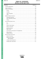
MASTER TABLE OF CONTENTS FOR ALL SECTIONS
RETURN TO MAIN INDEX
Page
Safety .................................................................................................................................................i-iv
Installation.............................................................................................................................Section A
Technical Specifications ..............................................................................................................A-2
Safety Precautions ......................................................................................................................A-3
Location and Ventilation ..............................................................................................................A-3
Pre-Operation Engine Service ....................................................................................................A-4
Electrical Output Connections.....................................................................................................A-5
Operation...............................................................................................................................Section B
Safety Instructions.......................................................................................................................B-2
General Description ....................................................................................................................B-2
Design Features..........................................................................................................................B-3
Controls and Settings..................................................................................................................B-3
Engine Operation ........................................................................................................................B-5
Welder Operation ........................................................................................................................B-7
Auxiliary Power ...........................................................................................................................B-9
Accessories ..........................................................................................................................Section C
Maintenance ..........................................................................................................................Section D
Theory of Operation .............................................................................................................Section E
Troubleshooting and Repair ................................................................................................Section F
Electrical Diagrams ..............................................................................................................Section G
Parts Manual ................................................................................................................................P-358
RANGER 250
Return to Master TOC
Section A-1
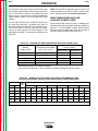
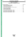
TABLE OF CONTENTS
- INSTALLATION SECTION -
Section A-1
Installation.............................................................................................................................Section A
Technical Specifications ..............................................................................................................A-2
Safety Precautions ......................................................................................................................A-3
Location and Ventilation ..............................................................................................................A-3
Storing ..................................................................................................................................A-3
Stacking ................................................................................................................................A-3
Angle of Operation................................................................................................................A-3
Lifting ....................................................................................................................................A-3
Additional Safety Precautions .....................................................................................................A-4
Return to Master TOC
High Altitude Operation.........................................................................................................A-4
High Temperature Operation ................................................................................................A-4
Towing...................................................................................................................................A-4
Pre-Operation Engine Service ....................................................................................................A-4
Oil .........................................................................................................................................A-4
Fuel.......................................................................................................................................A-4
Engine Cooling System ........................................................................................................A-4
Battery Connections .............................................................................................................A-5
Muffler Outlet Pipe ................................................................................................................A-5
Spark Arrester.......................................................................................................................A-5
High Frequency Generators for TIG Applications.................................................................A-5
Return to Master TOC
Remote Control.....................................................................................................................A-5
Welding Terminals ................................................................................................................A-5
Electrical Output Connections.....................................................................................................A-5
Machine Grounding ..............................................................................................................A-5
Welding Output Cables.........................................................................................................A-6
Cable Installation ............................................................................................................A-7
Auxiliary Power Receptacles ................................................................................................A-7
Return to Master TOC
Standby Power Connections ................................................................................................A-7
RANGER 250
Return to Master TOC
Return to Section TOC
A-2
INSTALLATION
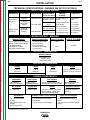
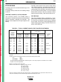
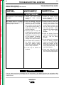
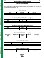
TECHNICAL SPECIFICATIONS - RANGER 250 (K1725-1/K1725-2)
INPUT - GASOLINE ENGINE
Make/Model
Description
Onan P216
(K1725-1)
Return to Master TOC
Kohler CH20
(K1725-2)
Return to Section TOC
A-2
2 cylinder
16 HP @
3600 RPM
(Onan)
Speed (RPM)
Displacement
cu. in. (cu. cm.)
High Idle 3700
44 (714) - Onan
38 (624) - Kohler
Full Load 3500
Starting
System
12 VDC Battery &
Starter
Low Idle 2400
Fuel: 12 gal.
45.4 L
Bore x Stroke inch (Group 58; 435 cold
(mm)
crank amps)
3.25 x 2.625
(83 x 67) (Onan)
20 HP @
3600 RPM
(Kohler)
Capacities
Battery Charger
20 A. regulated (K1725-1)
15 A. regulated (K1725-2)
3.03 x 2.64
(77 x 67) (Kohler)
(Push Button Start)
Oil: 1.8 Qts.
1.7 L (Onan)
Oil: 2.0 Qts.
1.9 L (Kohler)
Cooling System:
Air-Cooled
RATED OUTPUT - WELDER
Welding Output
Volts at Rated Amps
CC STICK & PIPE DC Output
STICK / PIPE Output Range
TIG Output Range
CV WIRE DC Output
CV WIRE Output Range
25
20
20
25
14
Duty Cycle Max.
Volts at 250 Amps
to 250 Amps
to 250 Amps
Volts at 250 Amps
to 28 Volts
OCV @ 3700 RPM
100%
80 Volts
100%
OUTPUT - GENERATOR
Auxiliary Power1
8,000 Watts, 60 Hz
120/240 Volts
100% Duty Cycle
Return to Master TOC
Return to Section TOC
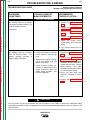
PHYSICAL DIMENSIONS
Height
Width
Depth
Weight
30.00* in.
762.0 mm
21.50 in.
546.0 mm
42.25 in.
1073.0 mm
452 lbs. (205 kg.) K1725-1
434 lbs. (197 kg.) K1725-2
* Top of enclosure, add 6.0” (152 mm) for exhaust
ENGINE COMPONENTS
Lubrication
Valve Lifters
Fuel System
Full Pressure
with Full Flow Filter
Solid (Onan)
Hydraulic (Kohler)
Vacuum Pulse Pump (Onan)
Mechanical Fuel Pump (Kohler)
Air Cleaner
Engine Idler
Muffler
Receptacles
Return to Master TOC
Return to Section TOC
Duel Element
Two 120 VAC Duplex
(5-20R)
One 120/240 VAC Dual
Voltage
Full KVA (14-50R)
Automatic Idler
Governor
Engine Protection
Low noise muffler: Top outlet
can be rotated. Made from
long life, aluminized steel.
Auxiliary Power Circuit Breaker
Two 20 Amp for Two Duplex
Receptacle
Two 35 Amp for Dual Voltage
Mechanical Governor
5% Regulation
Shutdown on low oil
pressure.
Other Circuit Breakers
25 Amp for Battery Charging
Circuit
150 Amp for 42 Volt Wire Feeder
Power
1. Output rating in watts is equivalent to volt-amperes at unity power factor. Output voltage is within ± 10% at all loads up to rated capacity. When welding,
available auxiliary power will be reduced.
RANGER 250
Return to Master TOC
Return to Master TOC
Return to Master TOC
Return to Section TOC
Return to Section TOC
Return to Section TOC
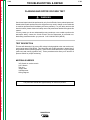
A-3
INSTALLATION
Read this entire installation section before you
start installation.
SAFETY PRECAUTIONS
WARNING
Do not attempt to use this equipment until you have
thoroughly read the engine manufacturer’s manual
supplied with your welder. It includes important safety
precautions, detailed engine starting, operating and
maintenance instructions and parts lists.
ELECTRIC SHOCK can kill.
• Do not touch electrically live
parts or electrode with skin or
wet clothing.
• Insulate yourself from work and
ground.
• Always wear dry insulating
gloves.
ENGINE EXHAUST can kill.
• Use in open, well ventilated
areas or vent exhaust outside.
• Do not stack anything near the
engine.
MOVING PARTS can injure.
• Do not operate with doors open
or guards off.
• Stop engine before servicing.
• Keep away from moving parts.
Return to Master TOC
STORING
1. Store the machine in a cool, dry place when it is
not in use. Protect it from dust and dirt. Keep it
where it can’t be accidentally damaged from construction activities, moving vehicles, and other hazards.
2. If you will be storing the machine for over 30 days,
you should drain the fuel to protect fuel system and
carburetor parts from gum deposits. Empty all fuel
from the tank and run the engine until it stops from
lack of fuel. If you prefer, you can treat the gasoline with a stabilizer to prevent deterioration rather
than drain the system. Follow the stabilizer manufacturer’s instructions. Add the correct amount of
stabilizer for the size of the fuel tank. Fill the tank
with clean, fresh gasoline. Run the engine for two
to three minutes to circulate the stabilizer through
the carburetor.
3. While the engine is still warm, drain the oil and refill
with fresh 10W30 oil. Change the oil filter.
4. Remove the spark plugs and add one to two tablespoons of engine oil or rust inhibitor into each cylinder. Replace the spark plugs but do not connect
the plug leads. Crank the engine two or three
times to distribute the oil.
5. Clean any dirt or debris from the cylinder and cylinder head fins and other exterior surfaces.
STACKING
Ranger 250 machines CANNOT be stacked.
ANGLE OF OPERATION
See additional safety information at the front of this
manual.
Only qualified personnel should install, use, or
service this equipment.
LOCATION AND VENTILATION
Return to Section TOC
A-3
The welder should be located to provide an unrestricted flow of clean, cool air to the cooling air inlets and to
avoid restricting the cooling air outlets. Also, locate the
welder so that the engine exhaust fumes are properly
vented to an outside area.
Engines are designed to run in the level condition,
which is where the optimum performance is achieved.
The maximum angle of continuous operation is 15
degrees in any direction. If the engine is to be operated at an angle, provisions must be made for checking
and maintaining the oil level at the normal (FULL) oil
capacity in the crankcase.
When operating the welder at an angle, the effective
fuel capacity will be slightly less than the specified 12
gallons (45.4 liters).
LIFTING
The Ranger 250 weighs approximately 452 lbs./205 kg.
with a full tank of gasoline. A lift bail is mounted to the
machine and should always be used when lifting it.
RANGER 250
Return to Master TOC
Return to Section TOC
A-4
A-4
INSTALLATION
ADDITIONAL SAFETY PRECAUTIONS
WARNING
FALLING EQUIPMENT can cause
injury.
• Do not lift this machine using lift bail if
it is equipped with a heavy accessory
such as trailer or gas cylinder.
PRE-OPERATION ENGINE SERVICE
Read and understand the information about the gasoline engine in the Operation and Maintenance sections of this manual before you operate the Ranger
250.
WARNING
• Lift only with equipment of adequate lifting capacity.
• Keep hands away from the engine muffler or HOT
engine parts.
• Be sure machine is stable when lifting.
• Stop the engine and allow it to cool before fueling.
• Do not smoke when fueling.
Return to Master TOC
Return to Section TOC
HIGH ALTITUDE OPERATION
At higher altitudes, output de-rating may be necessary.
For maximum rating, de-rate the welder output 3.5%
for every 1000 ft. (305m). Contact an authorized
engine service shop for modifications to operate above
5,000 ft. (1525m).
Return to Master TOC
Return to Section TOC
• Keep sparks and flame away from the fuel tank.
• Remove the fuel cap slowly to release pressure.
At temperatures above 30°C, output de-rating is necessary. For maximum output ratings, de-rate the
welder output 5% for every 10°C above 30°C.
OIL
The recommended trailer for use with this equipment
for road, in-plant and yard towing by a vehicle1 is
Lincoln’s K957-1. If the user adapts a non-Lincoln trailer, he must assume responsibility that the method of
attachment and usage does not result in a safety hazard nor damage the welding equipment. Some of the
factors to be considered are as follows:
The Ranger 250 is shipped with the engine
crankcase filled with high quality SAE 10W30 oil (API class CD or better). CHECK THE OIL
LEVEL BEFORE YOU START THE ENGINE. If it is
not up to the FULL mark on the dipstick, add oil as
required. Check the oil every four hours of running
time during the first 25 running hours. Refer to the
engine operator’s manual for specific oil recommendations and break-in information. The oil change interval
is dependent on the quality of the oil and the operating
environment. Refer to the engine operator’s manual
for the proper service and maintenance intervals.
1. Design capacity of trailer vs. weight of Lincoln
equipment and likely additional attachments.
FUEL
2. Proper support of, and attachment to, the base of
the welding equipment so there will be no undue
stress to the framework.
3. Proper placement of the equipment on the trailer to
insure stability side to side and front to back when
being moved and when standing by itself while
being operated or serviced.
Return to Master TOC
• Wipe up spilled fuel and allow the fumes to clear
before starting the engine.
HIGH TEMPERATURE OPERATION
TOWING
Return to Section TOC
• Fill the fuel tank at a moderate rate and do not overfill.
4. Typical conditions of use such as travel speed,
roughness of surface on which the trailer will be
operated, environmental conditions, and likely
maintenance.
5. Conformance with federal, state and local laws.1
1
Consult applicable federal, state and local laws regarding specific
requirements for use on public highways.
Use gasoline fuel only.
Fill the fuel tank with clean, fresh fuel. The
capacity of the fuel tank is 12 gallons (45.4
liters).
NOTE: The fuel tank is mounted below the engine, so
a fuel shutoff valve is not required.
ENGINE COOLING SYSTEM
Air to cool the engine is drawn in through the lower set
of louvers on the case back. It is important that the
intake air is not restricted. Allow a minimum clearance
of 2 feet (0.6m) from the case back to a vertical surface.
RANGER 250
Return to Master TOC
Return to Section TOC
A-5
INSTALLATION
BATTERY CONNECTIONS
HIGH FREQUENCY GENERATORS FOR
TIG APPLICATIONS
WARNING
BATTERY ACID CAN BURN EYES AND
SKIN.
• Wear gloves and eye protection and be
careful when working near a battery.
Follow the instructions printed on the
battery.
Return to Master TOC
Return to Section TOC
Use caution as the electrolyte is a strong acid that can
burn skin and damage eyes.
The Ranger 250 is shipped with the negative battery
cable disconnected. Make certain that the RUN-STOP
switch is in the STOP position. Remove the screws
from the rear battery tray using a screwdriver or a 3/8"
socket. Attach the negative battery cable to the negative battery terminal and tighten using a socket or
wrench.
NOTE: This machine is furnished with a wet charged
battery; if unused for several months, the battery may
require a booster charge. Be careful to charge the battery with the correct polarity. See the battery charging
instructions in the Maintenance section.
Return to Master TOC
Return to Section TOC
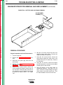
MUFFLER OUTLET PIPE
Using the clamp provided, secure the outlet pipe to the
outlet tube with the pipe positioned to direct the exhaust in the desired direction. Tighten using a socket or
wrench.
SPARK ARRESTER
Some federal, state or local laws may require spark
arresters in locations where unarrested sparks may
present a fire hazard. The standard muffler included
with this welder does not qualify as a spark arrester.
When required by local regulations, a suitable spark
arrester, such as the S24647, must be installed and
properly maintained. See the Accessories section for
more information.
Return to Master TOC
CAUTION
Return to Section TOC
A-5
The K930-2 TIG Module is suitable for use with the
Ranger 250. The Ranger 250 and any high frequency
generating equipment must be properly grounded.
See the K930-2 operating manual for complete instructions on installation, operation, and maintenance.
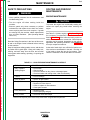
REMOTE CONTROL
The Ranger 250 is equipped with a 6-pin and a 14-pin
Amphenol connector. The 6-pin connector is for connecting the K857 or K857-1 Remote Control (optional)
or for TIG welding, the K870 foot Amptrol or the K9632 hand Amptrol.
When in the CC-STICK, PIPE, and CV-WIRE modes
and when a remote control is connected to the
Amphenol, the auto-sensing circuit in the Ranger 250
automatically switches the OUTPUT control from control at the welder to remote control.
The 14-pin connector is used to directly connect a wire
feeder. In the CV-WIRE mode, the Ranger 250 autosensing circuit automatically makes the Ranger 250
OUTPUT control inactive and the wire feeder voltage
control active when the control cable is connected to
the 14-pin connector.
NOTE: When a wire feeder with a built in welding voltage control is connected to the 14-pin connector, do
NOT connect anything to the 6-pin connector.
WELDING TERMINALS
The Ranger 250 is equipped with a toggle switch for
selecting “hot” welding terminals when in the “WELD
TERMINALS ON” position or “cold” welding terminals
when in the “REMOTELY CONTROLLED” position.
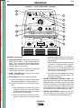
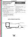
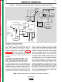
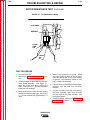
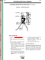
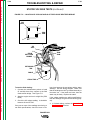
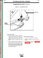
ELECTRICAL OUTPUT
CONNECTIONS
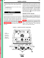
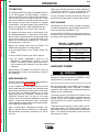
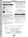
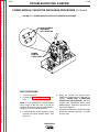
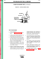
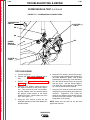
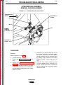
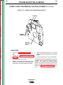
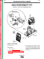
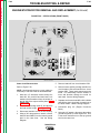
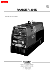
See Figure A.1 for the location of the 120 and 240 volt
receptacles, weld output terminals, and ground stud.
MACHINE GROUNDING
An incorrect spark arrester may lead to engine damage
or may adversely affect performance.
Because this portable engine driven welder
creates its own power, it is not necessary to connect its
frame to an earth ground, unless the machine is connected to premises wiring (home, shop, etc.)
RANGER 250
Return to Master TOC
Return to Section TOC
A-6
INSTALLATION
In general, if the machine is to be grounded, it should
be connected with a #8 or larger copper wire to a solid
earth ground such as a metal water pipe going into the
ground for at least ten feet and having no insulated
joints, or to the metal framework of a building which
has been effectively grounded. The U.S. National
Electrical Code lists a number of alternate means of
grounding electrical equipment. A machine grounding
stud marked with the
ground symbol is provided
on the front of the welder.
To prevent dangerous electric shock, other equipment
to which this engine driven welder supplies power
must:
a) Be grounded to the frame of the welder using a
grounded type plug.
b) Be double insulated.
WARNING
WELDING OUTPUT CABLES
Return to Master TOC
Do not ground the machine to a pipe that carries explosive or combustible material.
Return to Section TOC
A-6
With the engine off, connect the electrode and work
cables to the output terminals. The welding process
dictates the polarity of the electrode cable. These connections should be checked periodically and tightened
with a wrench.
When this welder is mounted on a truck or trailer, its
frame must be securely connected to the metal frame
of the vehicle. When connected to premises wiring
such as that in a home or shop, the welder frame must
be connected to the system earth ground. See further
connection instructions in the section entitled Standby
Power Connections as well as the article on grounding in the latest U.S. National Electrical Code and the
local code.
Table A.1 lists recommended cable sizes and lengths
for rated current and duty cycle. Length refers to the
distance from the welder to the work and back to the
welder. Cable diameters are increased for long cable
lengths to reduce voltage drops. Avoid coiling long
cables on the machine when welding.
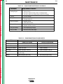
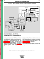
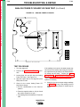
FIGURE A.1 – RANGER 250 OUTPUT CONNECTIONS
G3668
K NO.- CODE - SERIAL NO.
START
CHOKE
RUN
VM
HIGH
Hobbs
QUARTZ
IDLER
0 0 0 0 0 0
Return to Master TOC
Return to Section TOC
HOURS
AUTO
STOP
1. 120 VAC
RECEPTACLES
OUTPUT
22 CV
155 CC
20 CV
120 CC
24 CV
190 CC
17 CV
85 CC
2. 120/240 VAC
RECEPTACLES
26 CV
220 CC
14 CV
50 CC
3. WELD OUTPUT
TERMINALS
12 CV
20 CC
28 CV
250 CC
THE LINCOLN ELECTRIC COMPANY CLEVELAND, OHIO USA
WELD MODE
ARC CONTROL
0
-2
CV-WIRE
4. GROUND STUD
NRTL/C
NEUTRAL GROUND TO FRAME
+2
WELD
WIRE FEEDER
TERMINALS ON VOLTMETER
+4
-4
PIPE
+6
-6
CC-STICK
+8
-8
TOUCH START TIG
SOFT
+10
-10
CRISP
CIRCUIT
BREAKERS
REMOTELY
CONTROLLED
120/240 V
120 V
Return to Master TOC
Return to Section TOC
1
2
SIMULTANEOUS WELDING AND POWER
WELD CURRENT
AMPS
AUX. POWER
WATTS
240 V. RECEPTACLE
AMPS
0
100
150
200
250
8000
5000
3000
1500
0
33
21
13
6
0
AUXILIARY POWER RATING
WELDER OUTPUT RATING
AMPS
DUTY CYCLE
VOLTS
250 DC
100%
25
WATTS
DUTY CYCLE
VOLTS
8,000
100%
120/240
AVAILABLE POWER IS REDUCED WHILE WELDING
SINGLE PHASE 60 HZ
80V MAX OCV AT RATED 3700 RPM
3
RANGER 250
4
Return to Master TOC
Return to Section TOC
A-7
INSTALLATION
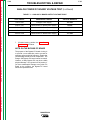
TABLE A.1 – TOTAL COMBINED LENGTH
OF ELECTRODE AND WORK CABLES
Cable
Length
0-100 ft. (0-30 meters)
100-200 ft. (30-46 meters)
150-200 ft. (46-61 meters)
Cable Size for
250 Amps
100% Duty Cycle
1 AWG
1 AWG
1/0 AWG
Return to Master TOC
Return to Section TOC
Install the welding cables to your Ranger 250 as follows.
1. The engine must be OFF to install welding cables.
2. Remove the flanged nuts from the output terminals.
3. Connect the electrode holder and work cables to
the weld output terminals. The terminals are identified on the case front.
4. Tighten the flanged nuts securely.
5. Be certain that the metal piece you are welding (the
“work”) is properly connected to the work clamp
and cable.
6. Check and tighten the connections periodically.
Return to Master TOC
Return to Master TOC
CAUTION
Return to Section TOC
two separate 120 VAC branch circuits (these circuits
cannot be paralleled). Output voltage is within ±10% at
all loads up to rated capacity.
The 120 VAC auxiliary power receptacles should only
be used with three-wire grounded type plugs or
approved double insulated tools with two-wire plugs.
The current rating of any plug used with the system
must be at least equal to the current capacity of the
associated receptacle.
NOTE: The 240 VAC receptacle has two 120 VAC circuits, but they are of opposite polarities and cannot be
paralleled.
CABLE INSTALLATION
Return to Section TOC
A-7
• Loose connections will cause the output terminals to
overheat. The terminals may eventually melt.
• Do not cross the welding cables at the output terminal connection. Keep the cables isolated and separate from one another.
AUXILIARY POWER RECEPTACLES
The auxiliary power of the Ranger 250 consists of two
20 amp-120 VAC (5-20R) duplex receptacles and one
50 amp 120/240 VAC (14-50R) receptacle. The 240
VAC receptacle can be split for single-phase 120 VAC
operation.
The auxiliary power capacity is 8,000 watts of 60 Hz,
single-phase power. The auxiliary power capacity rating in watts is equivalent to volt-amperes at unity power
factor. The maximum permissible current of the 240
VAC output is 33 amps. The 240 VAC output can be
split to provide two separate 120 VAC outputs with a
maximum permissible current of 33 amps per output to
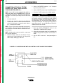
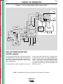
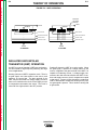
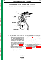
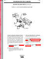
STANDBY POWER CONNECTIONS
The Ranger 250 is suitable for temporary, standby or
emergency power using the engine manufacturer’s recommended maintenance schedule.
The Ranger 250 can be permanently installed as a
standby power unit for 240 VAC, three-wire, singlephase, 35 amp service. Connections must be made by
a licensed electrician who can determine how the
120/240 VAC power can be adapted to the particular
installation and comply with all applicable electrical
codes. The following information can be used as a
guide by the electrician for most applications. Refer to
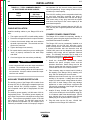
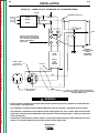
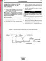
the connection diagram in Figure A-2.
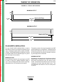
1. Install the double-pole, double-throw switch
between the power company meter and the
premises disconnect. Switch rating must be the
same or greater than the customer’s premises disconnect and service over current protection.
2. Take necessary steps to assure load is limited to
the capacity of the Ranger 250 by installing a 35
amp, 240 VAC double-pole circuit breaker.
Maximum rated load for each leg of the 240 VAC
auxiliary is 33 amperes. Loading above the rated
output will reduce output voltage below the allowable ±10% of rated voltage, which may damage
appliances or other motor-driven equipment and
may result in overheating of the Ranger 250 engine
and/or alternator windings.
3. Install a 50 amp, 120/240 VAC plug (NEMA Type
14-50) to the double-pole circuit breaker using No.
6, 4-conductor cable of the desired length. (The 50
amp, 120/240 VAC plug is available in the optional
K802R plug kit or as part number T12153-9.)
4. Plug this cable into the 50 amp, 120/240 VAC
receptacle on the Ranger 250 case front.
RANGER 250
Return to Master TOC
Return to Section TOC
A-8
A-8
INSTALLATION
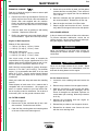
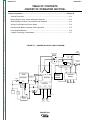
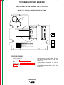
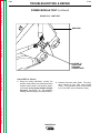
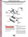
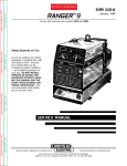
FIGURE A.2 – CONNECTION OF THE RANGER 250 TO PREMISES WIRING
240 VOLT
GROUNDED CONDUCTOR
POWER
240 Volt
60 Hz.
3-Wire
Service
120 VOLT
COMPANY
120 VOLT
METER
NEUTRAL
BUS
Return to Master TOC
Return to Section TOC
N
DOUBLE POLE DOUBLE THROW
SWITCH RATING TO BE THE SAME
AS OR GREATER THAN PREMISES
SERVICE OVERCURRENT
PROTECTION.
Return to Master TOC
Return to Section TOC
GROUND
35AMP
240 VOLT
50 AMP, 120/240
VOLT PLUG
NEMA TYPE 14-50
240 VOLT
PREMISES
DISCONNECT AND
SERVICE
OVERCURRENT
PROTECTION
DOUBLE
POLE
CIRCUIT
BREAKER
GND
N
50 AMP, 120/240 VOLT
RECEPTACLE
NOTE: No. 8 COPPER CONDUCTOR CABLE SEE
NATIONAL ELECTRICAL CODE FOR ALTERNATE WIRE
SIZE RECOMMENDATIONS.
WARNING
Return to Master TOC
• Only a licensed, certified, trained electrician should install the machine to a premises or residential electrical system. Be certain that:
Return to Section TOC
LOAD
• The installation complies with the National Electrical Code and all other applicable electrical codes.
• The premises is isolated and no feedback into the utility system can occur. Certain state and local laws
require the premises to be isolated before the generator is linked to the premises. Check your state and
local requirements.
• A double-pole, double-throw transfer switch in conjunction with the properly rated double-throw circuit
breaker is connected between the generator power and the utility meter.
RANGER 250
Return to Master TOC
Section B-1
Section B-1
TABLE OF CONTENTS
- OPERATION SECTION -
Operation...............................................................................................................................Section B
Operating Instructions .................................................................................................................B-2
Safety Instructions.......................................................................................................................B-2
General Description ....................................................................................................................B-2
Design Features..........................................................................................................................B-3
Controls and Settings..................................................................................................................B-3
Return to Master TOC
Engine Controls ....................................................................................................................B-4
Welding Controls ..................................................................................................................B-5
Engine Operation ........................................................................................................................B-5
Before Starting the Engine ...................................................................................................B-5
Starting the Engine ...............................................................................................................B-6
Stopping the Engine .............................................................................................................B-6
Welder Operation ........................................................................................................................B-7
General Operation ................................................................................................................B-7
Stick Welding ........................................................................................................................B-8
Constant Current (CC-Stick) Welding.............................................................................B-8
Pipe Welding...................................................................................................................B-8
Return to Master TOC
Return to Master TOC
TIG Welding..........................................................................................................................B-9
Wire Welding-CV ..................................................................................................................B-9
Arc Gouging..........................................................................................................................B-9
Auxiliary Power ...........................................................................................................................B-9
Simultaneous Welding and Auxiliary Power Loads ............................................................B-10
RANGER 250
Return to Master TOC
Return to Section TOC
B-2
OPERATION
WARNING
OPERATING INSTRUCTIONS
Read and understand this entire section before operating your Ranger 250.
ENGINE EXHAUST can kill.
SAFETY INSTRUCTIONS
• Use in open, well ventilated areas or
vent exhaust to the outside.
• Do not stack anything on or near the
engine.
WARNING
Return to Master TOC
Do not attempt to use this equipment until you have
thoroughly read all the operating and maintenance
manuals supplied with your machine. They include
important safety precautions; detailed engine starting,
operating and maintenance instructions and parts lists.
Return to Section TOC
B-2
MOVING PARTS can injure.
• Do not operate this equipment with any
of its doors open or guards off.
• Stop the engine before servicing it.
ELECTRIC SHOCK can kill.
• Keep away from moving parts.
• Do not touch electrically live parts such
as output terminals or internal wiring.
• Insulate yourself from the work and
ground.
Only qualified personnel should install, use, or service this equipment.
• Always wear dry insulating gloves.
ADDITIONAL SAFETY PRECAUTIONS
FUMES AND GASES can be dangerous.
Return to Master TOC
Return to Section TOC
• Keep your head out of fumes.
• Use ventilation or exhaust to remove
fumes from breathing zone.
Always operate the welder with the hinged door closed
and the side panels in place. These provide maximum
protection from moving parts and insure proper cooling
air flow.
GENERAL DESCRIPTION
WELDING SPARKS can cause
fire or explosion.
• Keep flammable material away.
• Do not weld on containers that have held
combustibles.
The Ranger 250 is a gasoline-engine-powered DC
multi-process welding power source and 120 / 240
VAC power generator. The engine drives a generator
that supplies three-phase power for the DC welding circuit and single-phase power for the AC auxiliary outlets. The DC welding control system uses state of the
art Chopper Technology (CT™) for superior welding
performance.
ARC RAYS can burn.
Return to Master TOC
Return to Section TOC
• Wear eye, ear, and body protection.
RANGER 250
Return to Master TOC
Return to Master TOC
Return to Master TOC
Return to Master TOC
Return to Section TOC
Return to Section TOC
Return to Section TOC
Return to Section TOC
B-3
OPERATION
B-3
• Longer engine life, reduced noise emissions and
greater fuel economy with the automatic engine idler.
DESIGN FEATURES
• Single, full-range output control dial.
• 4 welding modes: CC-stick, downhill stick welding on
pipe, CV wire welding and Touch-Start TIG™ (eliminates high frequency and tungsten contamination).
• Conveniently located engine maintenance label
under top engine door.
• Engine hour meter for scheduled maintenance.
• Output at welding terminals controlled by electronic
contactor. Can be switched to “On”, or to “Remotely
Controlled”. Contactor auto-activated when connected. 6-pin connector for remote output.
• Automatic engine shutdown protection for low oil
pressure.
• Many wire feeder combinations: 14-pin connector for
Lincoln wire feeders LN-25, LN-23P, LN-7, LN-8
operates when using a Lincoln wire feeder with the
appropriate control cable.
• Oil drain valve (no tools required).
• Smart machine! Remote operation and Magnum®
spool gun; 42VAC for LN-742 and Cobramatic® wire
feeders.
• Wire feed voltmeter switch matches polarity of wire
feeder voltmeter to polarity of electrode.
• 12 gallon fuel capacity allows you to run an extended day.
• Easily check fuel level during operation and refuelling with highly visible fuel gauge located next to
the fuel cap on case top side.
• Electric start. Reduce abnormal charging thanks to
a backlit battery charger system light indicator.
• 8,000 watts of continuous duty AC generator power.
• Up to 33 amps at 240V from the 120V/240V receptacle. Circuit breaker protection.
• Two 120V 20A duplex receptacles. Circuit breaker
protection. Will operate up to a 9” grinder.
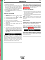
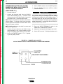
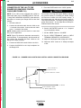
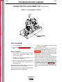
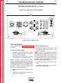
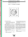
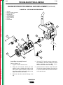
CONTROLS AND SETTINGS
The gasoline engine stop/start and idler controls are
located on the case front panel. The welder controls are
also located here. See Figure B.1.
RANGER 250
Return to Master TOC
Return to Section TOC
B-4
B-4
OPERATION
FIGURE B.1 – CASE FRONT PANEL CONTROLS
1
G3668
K NO.- CODE - SERIAL NO.
6
START
CHOKE
RUN
VM
HIGH
Hobbs
QUARTZ
IDLER
0 0 0 0 0 0
HOURS
OUTPUT
22 CV
155 CC
20 CV
120 CC
24 CV
190 CC
17 CV
85 CC
12 CV
20 CC
NRTL/C
28 CV
250 CC
THE LINCOLN ELECTRIC COMPANY CLEVELAND, OHIO USA
WELD MODE
3
26 CV
220 CC
14 CV
50 CC
7
4
AUTO
STOP
NEUTRAL GROUND TO FRAME
2
ARC CONTROL
0
-2
CV-WIRE
+2
WELD
WIRE FEEDER
TERMINALS ON VOLTMETER
+4
-4
5
PIPE
+6
-6
CC-STICK
+8
-8
TOUCH START TIG
SOFT
+10
-10
CRISP
REMOTELY
CONTROLLED
13
Return to Master TOC
Return to Section TOC
8
9
12
CIRCUIT
BREAKERS
120/240 V
11
120 V
SIMULTANEOUS WELDING AND POWER
WELD CURRENT
AMPS
AUX. POWER
WATTS
240 V. RECEPTACLE
AMPS
0
100
150
200
250
8000
5000
3000
1500
0
33
21
13
6
0
DUTY CYCLE
VOLTS
250 DC
100%
25
80V MAX OCV AT RATED 3700 RPM
10
AUXILIARY POWER RATING
WELDER OUTPUT RATING
AMPS
WATTS
DUTY CYCLE
VOLTS
8,000
100%
120/240
AVAILABLE POWER IS REDUCED WHILE WELDING
SINGLE PHASE 60 HZ
receptacles (approximately 100 watts minimum), the engine accelerates and operates
at high speed.
Return to Master TOC
Return to Section TOC
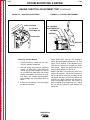
ENGINE CONTROLS
1. RUN/STOP SWITCH: RUN position energizes the
engine prior to starting. STOP position stops the
engine. The oil pressure interlock switch prevents
battery drain if the switch is left in the RUN position
and the engine is not operating.
c. When welding ceases or the AC power load
is turned off, a fixed time delay of approximately 12 seconds starts. If the welding or
AC power load is not restarted before the
end of the time delay, the idler reduces the
engine speed to low idle speed.
2. CHOKE: When pulled out, it closes the choke valve
on the engine carburetor for quick starting.
3. START PUSHBUTTON: Energizes the starter
motor to crank the engine.
d. The engine will automatically return to high
idle speed when the welding load or AC
power load is reapplied.
4. IDLER SWITCH: Has two positions as follows:
A) In the HIGH position, the engine runs at the high
idle speed controlled by the engine governor.
Return to Master TOC
Return to Section TOC
B) In the AUTO position, the idler operates as follows:
a. When switched from HIGH to AUTO or after
starting the engine, the engine will operate
at high speed for approximately 12 seconds
and then go to low idle speed.
b. When the electrode touches the work or
power is drawn from the auxiliary power
5. ENGINE ALTERNATOR TROUBLE LIGHT: The
yellow engine alternator light is off when the battery
charging system is functioning normally. If the light
turns on, the alternator or the voltage regulator may
not be operating correctly. The light may also come
on if the battery is not holding a charge. It is normal
for the light to come on while starting the engine.
6. ENGINE HOUR METER: Displays the total time
that the engine has been running. This meter is
useful for scheduling prescribed maintenance.
RANGER 250
Return to Master TOC
Return to Section TOC
B-5
OPERATION
WELDING CONTROLS
7. OUTPUT CONTROL: The OUTPUT dial provides
continuous control of the welding current or welding voltage depending on the selected welding
mode. This control is not active in the CC-STICK,
PIPE, and CV-WIRE modes when a remote control or wire feeder with remote control is connected to either the 6-pin or 14-pin Amphenol.
12.
WELD TERMINALS CONTROL SWITCH: In the
WELD TERMINALS ON position, the weld output
is electrically hot all the time. In the REMOTELY
CONTROLLED position, the weld output is controlled by a wire feeder or amptrol device, and is
electrically off until a remote switch is depressed.
13.
WIRE FEEDER VOLTMETER SWITCH: Matches
the polarity of the wire feeder voltmeter to the
polarity of the electrode.
8. WELD MODE SELECTOR SWITCH: This switch
provides four selectable welding modes:
Return to Master TOC
Return to Master TOC
Return to Section TOC
Return to Section TOC
•
•
•
•
CC-STICK mode: In this mode, the ARC CONTROL sets the short circuit current during stick
welding (arc-force). Increasing the number from
-10 to +10 increases the short circuit current and
prevents sticking of the electrode to the plate
while welding. This can also increase spatter. It
is recommended that the ARC CONTROL be set
to the minimum number without electrode sticking. Start with a setting at 0.
CV-WIRE mode: In this mode, turning the ARC
CONTROL clockwise from -10 (soft) to +10 (crisp)
changes the arc from soft and washed-in to crisp
and narrow. It acts as an inductance control. The
proper setting depends on the procedure and
operator preference. Start with a setting at 0.
Return to Master TOC
11.
Return to Section TOC
ENGINE OPERATION
WARNING
CV-WIRE
PIPE
CC-STICK
TOUCH START TIG
9. ARC CONTROL: The ARC CONTROL WIRE/
STICK dial is active in the CV-WIRE and CCSTICK modes, and has different functions in
these modes. This control is not active in the TIG
and PIPE modes.
10.
B-5
14-PIN AMPHENOL: For attaching wire feeder
control cables to the Ranger 250. Includes contactor closure circuit, auto-sensing remote control
circuit, and 120V and 42V power. The remote
control circuit operates the same as the 6-pin
Amphenol. See below.
6-PIN AMPHENOL: For attaching optional
remote control equipment. When in the CCSTICK, PIPE, and CV-WIRE modes and when a
remote control is connected to the Amphenol, the
auto-sensing circuit in the Ranger 250 automatically switches the OUTPUT control from control at
the welder to remote control.
DO NOT RUN THE ENGINE AT EXCESSIVE
SPEEDS. The maximum allowable high idle speed for
the Ranger 250 is 3750 RPM, no load. Do NOT adjust
the governor screw on the engine. Severe personal
injury and damage to the machine can result if it is
operated at speeds above the maximum rated speed.
Read and understand all safety instructions included in
the engine operator’s manual that is shipped with your
Ranger 250.
BEFORE STARTING THE ENGINE
Check and fill the engine oil level:
1. Be sure the machine is on a level surface.
2. Open top engine door and remove the engine oil
dipstick and wipe it with a clean cloth. Reinsert the
dipstick and check the level on the dipstick.
3. Add oil (if necessary) to bring the level up to the full
mark. Do not overfill. Close engine door.
4. See the Maintenance section for specific oil recommendations.
Check and fill the engine fuel tank:
WARNING
GASOLINE can cause fire or
explosion.
• Stop engine when fueling.
• Do not smoke when fueling.
• Do not overfill tank.
• Avoid contact with skin or breathing of vapor.
• Keep sparks and flame away from tank.
When using the TOUCH START TIG mode, the
OUTPUT control on the front of the Ranger 250
sets the maximum current range.
RANGER 250
Return to Master TOC
Return to Section TOC
B-6
OPERATION
1. Remove the fuel tank cap.
2. Fill the tank approximately 4 inches (100mm) from
the top of the filler neck to allow for fuel expansion.
(Observe the fuel gauge while filling.) DO NOT
FILL THE TANK TO THE POINT OF OVERFLOW.
3. Replace the fuel cap and tighten securely.
1. Remove all plugs connected to the AC power
receptacles.
Return to Master TOC
Return to Section TOC
2. Set the IDLER switch to AUTO.
/
Return to Master TOC
Return to Master TOC
1. Remove all welding and auxiliary power loads and
allow the engine to run at low idle speed for a few
minutes to cool the engine.
2. Stop the engine by placing the RUN-STOP switch in
the STOP position.
NOTE: A fuel shut off valve is not required on the
Ranger 250 because the fuel tank is mounted below
the engine.
3. Set the RUN/STOP switch to RUN.
4. Pull the choke to the full out position.
5. Press and hold the engine START button until the
engine starts.
6. Release the engine START button when the
engine starts.
7. Push the choke back in.
8. The engine will run at high idle speed for approximately 12 seconds and then go to low idle speed.
Allow the engine to warm up at low idle for several minutes before applying a load and/or switching to high idle. Allow a longer warm up time in
cold weather.
Return to Section TOC
NOTE: Starting a Ranger 250 for the first time, or after
an extended period of time of not operating, will take
longer than normal. The fuel pump has to fill the fuel
line and carburetor. If the engine will not start, see the
Troubleshooting section of this manual.
STOPPING THE ENGINE
4. See the Maintenance section for specific fuel recommendations.
STARTING THE ENGINE
Return to Section TOC
B-6
CAUTION
BREAK-IN PERIOD
Any engine will use a small amount of oil during its
“break-in” period. For the gasoline engine on the
Ranger 250, break-in is about 50 running hours.
Check the oil at least twice a day during break-in.
Change the oil after the first 25 hours of operation.
Change the oil filter at the second oil change. For more
details, see the Maintenance section of this manual.
CAUTION
During break-in, subject the Ranger 250 to moderate
loads. Avoid long periods running at idle. Before stopping the engine, remove all loads and allow the engine
to cool several minutes.
Operating the starter motor for more than 5 seconds
can damage the motor. If the engine fails to start,
release the START button and wait 10 seconds before
activating the starter again. Do NOT push the START
button while the engine is running because this can
damage the ring gear and/or the starter motor.
RANGER 250
Return to Master TOC
Return to Section TOC
B-7
OPERATION
WELDER OPERATION
GENERAL INFORMATION
WARNING
• Do not touch electrically live parts or electrodes with your skin or wet clothing.
• Do not breathe welding fumes or gases.
Return to Master TOC
• Use ventilation or exhaust to remove welding from the breathing area.
Return to Section TOC
B-7
The Ranger 250 can deliver from 40 to 250 amps of
constant current for DC stick welding or from 20 to 250
amps of constant voltage current for DC semiautomatic wire feed welding. DC TIG welding is possible
across the entire range from 20 to maximum rated output. Output can be adjusted by setting the OUTPUT
control dial and the ARC control dial on the output control panel to the settings that are best for your selected
welding process.
NOTE: An unstable or unsatisfactory welding arc can
result if welding cables are too long or are coiled on the
machine when welding. See Table A.1 in the
Installation section. Straighten out coiled cables
before welding.
• Keep flammable material away.
• Wear eye, ear, and body protection.
Return to Section TOC
Return to Master TOC
Return to Section TOC
Return to Master TOC
TABLE B.1 – TYPICAL RANGER 250 FUEL CONSUMPTION
Onan P216
16 hp @ 3600 rpm
gal./hr (liters/hr)
Kohler CH20
12 gallons-hours
gal./hr (liters/hr)
Running Time for
12 gallons-hours
Onan/Kohler
Low Idle - No Load
2400 R.P.M.
0.6 (2.3)
0.6 (2.3)
20/20
High Idle - No Load
3700 R.P.M.
0.8 (3.0)
0.8 (3.0)
15/15
DC Weld Output
250 Amps @ 25 Volts
1.7 (6.4)
1.4 (5.3)
7.0/8.6
Auxiliary Power
8,000 Watts
1.8 (6.8)
1.4 (5.3)
6.4/8.6
RANGER 250
Return to Master TOC
Return to Section TOC
B-8
OPERATION
STICK WELDING
The Ranger 250 can be used with a broad range of DC
stick electrodes.
The MODE switch provides two stick welding settings
as follows:
Return to Master TOC
Return to Master TOC
Return to Section TOC
Return to Section TOC
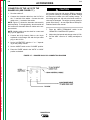
PIPE WELDING
This slope-controlled setting is intended for “out-ofposition” and “downhill” pipe welding where the operator would like to control the current level by changing
the arc length. The OUTPUT control dial adjusts the full
output range for pipe welding. The ARC control is not
active in the PIPE mode.
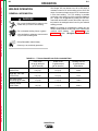
TABLE B.2 – TYPICAL CURRENT RANGES1 FOR TUNGSTEN ELECTRODES2
Tungsten
Electrode
Diameter
in. (mm)
DCEN (-)
DCEP (+)
1%, 2%
Thoriated
Tungsten
1%, 2%
Thoriated
Tungsten
0 .010
0.020
0.040
(.25)
(.50)
(1.0)
2-15
5-20
15-80
3
1/16
(1.6)
70-150
3/32
1/8
(2.4)
(3.2)
5/32
3/16
1/4
(4.0)
(4.8)
(6.4)
Approximate Argon Gas Flow Rate
C.F.H. (l/min.)
Aluminum
Stainless Steel
TIG TORCH
Nozzle
Size 4, 5
3-8
5-10
5-10
(2-4)
(3-5)
(3-5)
3-8
5-10
5-10
(2-4)
(3-5)
(3-5)
#4, #5, #6
10-20
5-10
(3-5)
9-13
(4-6)
#5, #6
150-250
250-400
15-30
25-40
13-17
15-23
(6-8)
(7-11)
11-15
11-15
(5-7)
(5-7)
#6, #7, #8
400-500
500-750
750-1000
40-55
55-80
180-125
21-25
23-27
28-32
(10-12)
(11-13)
(13-15)
13-17
18-22
23-27
(6-8)
(8-10)
(11-13)
#8, #10
3
3
1
When used with argon gas. The current ranges shown must be reduced when using argon/helium or pure helium shielding gases.
2
Tungsten electrodes are classified as follows by the American Welding Society (AWS):
Pure
EWP
1% Thoriated
EWTh-1
2% Thoriated
EWTh-2
Though not yet recognized by the AWS, Ceriated Tungsten is now widely accepted as a substitute for 2% Thoriated
Tungsten in AC and DC applications.
3
DCEP is not commonly used in these sizes.
TIG torch nozzle “sizes” are in multiples of 1/16ths of an inch:
# 4 = 1/4 in. (6 mm)
# 5 = 5/16 in. (8 mm)
# 6 = 3/8 in. (10 mm)
# 7 = 7/16 in. (11 mm)
# 8 = 1/2 in. (12.5 mm)
#10 = 5/8 in. (16 mm)
4
Return to Master TOC
The ARC control sets the short circuit current during
stick welding (arc-force). Increasing the number from
-10 to +10 increases the short circuit current and prevents sticking of the electrode to the plate while welding. This can also increase spatter. It is recommended
that the ARC control be set to the minimum number
without electrode sticking. Start with the dial set at 0.
CONSTANT CURRENT (CC-STICK) WELDING
The CC-STICK position of the MODE switch is
designed for horizontal and vertical-up welding with all
types of electrodes, especially low hydrogen. The
OUTPUT control adjusts the full output range for stick
welding.
Return to Section TOC
B-8
5
TIG torch nozzles are typically made from alumina ceramic. Special applications may require lava nozzles, which are
less prone to breakage, but cannot withstand high temperatures and high duty cycles.
RANGER 250
Return to Master TOC
Return to Section TOC
B-9
OPERATION
TIG WELDING
The TOUCH START TIG setting of the MODE switch is
for DC TIG (Tungsten Inert Gas) welding. To initiate a
weld, the OUTPUT control is first set to the desired current and the tungsten is touched to the work. During
the time the tungsten is touching the work there is very
little voltage or current and, in general, no tungsten
contamination. Then the tungsten is gently lifted off the
work in a rocking motion, which establishes the arc.
Return to Master TOC
Return to Master TOC
Return to Master TOC
Return to Section TOC
Return to Section TOC
The ARC CONTROL is not active in the TIG mode.
Return to Section TOC
B-9
The Ranger 250 can be used in a wide variety of DC
TIG welding applications. In general the “Touch Start”
feature allows contamination-free starting without the
use of a Hi-frequency unit. If desired, the K930-2 TIG
Module can be used with the Ranger 250. The following settings are for reference.
Some recommended solid wires for MIG welding are:
.035 (0.9 mm), and .045 (1.1 mm), L-50 and L-56, .035
(0.9 mm) and .045 (1.1 mm) Blue Max MIG 308 LS.
For any electrodes, including those above, the procedures should be kept within the rating of the machine.
ARC GOUGING
The Ranger 250 can be used for limited arc gouging.
For optimal performance, set the MODE switch to CCSTICK and the ARC CONTROL to +10.
Set the OUTPUT CONTROL to adjust output current to
the desired level for the gouging electrode being used
according to the ratings in Table B.3.
TABLE B.3 – CURRENT RANGE
PER ELECTRODE DIAMETER
Ranger 250 settings when using the K930-2 TIG
Module with an Amptrol or Arc Start Switch:
a. Set the MODE Switch to the TOUCH START TIG
setting.
Electrode
Diameter
Current Range
(DC, Electrode Positive)
1/8"
30-60 Amps
b. Set the “IDLER” Switch to the “AUTO” position.
5/32"
90-150 Amps
c. Set the "WELD TERMINALS” switch to the
“REMOTELY CONTROLLED” position. This will
keep the solid state contactor open and provide a
“cold” electrode until the Amptrol or Arc Start switch
is pressed.
3/16"
150-200 Amps
AUXILIARY POWER
When using the TIG Module, the OUTPUT control on
the Ranger 250 is used to set the maximum range of
the CURRENT.
WIRE WELDING-CV
Connect a wire feeder to the Ranger 250 according to
the instructions in the Accessories section.
In the CV-WIRE mode, the Ranger 250 can be used
with a broad range of flux cored wire (Innershield and
Outershield) electrodes and solid wires for MIG welding (gas metal arc welding). Welding can be finely
tuned using the ARC CONTROL. Turning the ARC
CONTROL clockwise from -10 (soft) to +10 (crisp)
changes the arc from soft and washed-in to crisp and
narrow. It acts as an inductance control. The proper
setting depends on the procedure and operator preference. Start with the dial set at 0.
Some recommended Innershield electrodes are:
NR-311, NS-3M, NR-207, NR-203 Ni 1%, NR-204-H.
Recommended Outershield electrodes are: 0S-70,
0S-71M.
WARNING
Be sure that any electrical equipment plugged into the
generator AC power receptacles can withstand a ±10%
voltage and a ±3% frequency variation.
Start the engine and set the IDLER control switch to
the desired operating mode. Full power is available
regardless of the welding control settings as long as no
welding current is being drawn.
The auxiliary power of the Ranger 250 consists of two
20 amp-120 VAC (5-20R) duplex receptacles and one
50 amp 120/240 VAC (14-50R) receptacle. The 240
VAC receptacle can be split for single-phase 120 VAC
operation.
The auxiliary power capacity is 8,000 watts of 60 Hz,
single-phase power. The auxiliary power capacity rating in watts is equivalent to volt-amperes at unity power
factor. The maximum permissible current of the 240
VAC output is 33 amps.
RANGER 250
Return to Section TOC
Return to Master TOC
Return to Section TOC
Return to Master TOC
B-10
B-10
OPERATION
The 240 VAC output can be split to provide two separate 120 VAC outputs with a maximum permissible current of 33 amps per output to two separate 20 amp
branch circuits. (These circuits cannot be paralleled.)
Output voltage is within ±10% at all loads up to rated
capacity.
NOTE: The 240 VAC receptacle has two circuits, each
of which measures 120 VAC to neutral. However, they
are of opposite polarity and cannot be paralleled.
SIMULTANEOUS WELDING AND
AUXILIARY POWER LOADS
The 120 VAC auxiliary power receptacles should only
be used with three-wire, grounded type plugs or
approved double-insulated tools with two-wire plugs.
The current rating of any plug used with the system
must be at least equal to the current capacity of the
associated receptacle. For extension cord lengths, see
Table B.5.
The auxiliary power ratings are with no welding load.
Simultaneous welding and power loads are specified in
Table B.4. The permissible currents shown assume
that current is being drawn from either the 120 VAC or
240 VAC supply (not both at the same time).
TABLE B.4 – RANGER 250 SIMULTANEOUS WELDING AND POWER LOADS
Welding
Output- Amps
Permissible Power-Watts
(Unity Power Factor)
0
100
150
200
250
8000
5000
3000
1500
0
Permissible Auxiliary
Current in Amps
@ 120 VAC*
40*
40*
25
12.5
0
@ 240 VAC**
33
21
12.5
6.3
0
Return to Master TOC
Return to Section TOC
* Each duplex receptacle is limited to 20 amps.
** Not to exceed 25 amps per 120 VAC branch circuit when splitting the 240 VAC output.
TABLE B.5 – RANGER 250 EXTENSION CORD LENGTH RECOMMENDATIONS
(Use the shortest length extension cord possible sized per the following table)
Current Voltage
Load
(Watts)
(Amps) (Volts)
15
120
1800
20
120
2400
15
240
3600
20
240
4800
33
240
8000
Maximum Allowable Cord Length in Ft. (m) for Conductor Size
14 AWG
30
60
(9)
(18)
12 AWG
10 AWG
8 AWG
Return to Master TOC
4 AWG
40
(12)
75
(23)
125
(38)
175
(53)
300
(91)
30
(9)
50
(15)
88
(27)
138
(42)
225
(69)
75
(23)
150
(46)
225
(69)
350
(107)
600
(183)
60
(18)
100
(30)
175
(53)
275
(84)
450
(137)
60
(18)
100
(30)
175
(53)
250
(76)
Conductor size is based on maximum 2.0% voltage drop.
Return to Section TOC
6 AWG
RANGER 250
Return to Master TOC
Section C-1
Section C-1
TABLE OF CONTENTS
- ACCESSORIES Accessories ..........................................................................................................................Section C
Options/Accessories ...................................................................................................................C-2
Field Installed Options .........................................................................................................C-2
TIG Welding Accessories .....................................................................................................C-2
Semiautomatic FCAW and MIG Welding Accessories .........................................................C-2
Connection of Lincoln Electric Wire Feeders .......................................................................C-3
Connection of the K867 Universal Adapter ....................................................................C-3
Connection of the LN-25 “Across the Arc” .....................................................................C-4
Connection of the LN-25 with K857 Remote Control.....................................................C-6
Connection of the LN-7 Using the K584 Control Cable .................................................C-7
Connection of the LN-8 Using the K595 Control Cable .................................................C-8
Connection of the LN-742 ..............................................................................................C-9
Return to Master TOC
Return to Master TOC
Return to Master TOC
Connection of the LN-25 with 42V Remote Output Control Module ..............................C-5
RANGER 250
Return to Master TOC
Return to Master TOC
Return to Section TOC
Return to Section TOC
C-2
ACCESSORIES
OPTIONS/ACCESSORIES
plugs rated at 15 amps each and one dual voltage, full
KVA plug rated at 120/240 volts, 50 amps.
FIELD INSTALLED OPTIONS
T12153-9 50 AMP, 120/240V POWER PLUG Provides one dual voltage plug for full KVA power.
The following options/accessories are available for
your Ranger 250 from your local Lincoln distributor.
K1783-9 TIG TORCH - For TIG welding with shielding
gas. Includes 25 feet of cable.
K1737-1 FOUR-WHEEL ALL-TERRAIN UNDERCARRIAGE - For moving by hand.
NOTE: TIG welding requires a Magnum™ TIG Gun,
appropriate Magnum Parts Kit and argon gas.
K1770-1 UNDERCARRIAGE (FACTORY) - For moving by hand on a smooth surface. One or two gas
cylinders can be mounted on the rear of the undercarriage with the installation of K1745-1 Cylinder
Holder(s).
K1739-1 CABLE CARRIER KIT - For use on K1737-1
and K1770-1 Undercarriages.
K1745-1 SINGLE GAS CYLINDER HOLDER - For use
on K1770-1 Undercarriage. One or two may be
installed on an undercarriage.
Return to Master TOC
Return to Master TOC
K886-2 CANVAS COVER - Protects machine when
not in use.
Return to Section TOC
TIG WELDING ACCESSORIES
K957-1 HEAVY DUTY, TWO-WHEEL TRAILER FOR
SMALL WELDERS - For road, off-road and in-plant
and yard towing. (For highway use, consult applicable
federal, state and local laws regarding requirements for
brakes, lights, fenders, etc.)
K1788-1 ROLL CAGE - Gives added damage protection.
Return to Section TOC
C-2
S24647 SPARK ARRESTER - Mounts inside exhaust
pipe.
K702 ACCESSORY KIT - Accessory set includes 35 ft.
(10.7 meters) 2 AWG electrode cable, 30 ft. (9.1
meters) 2 AWG work cable, headshield with No. 12 filter, GC300 work clamp and Cooltong 300 electrode
holder. Cables are rated at 250 amps, 40% duty cycle.
K857 28 ft. (8.5m) or K857-1 100 ft. (30.4m)
REMOTE CONTROL - Portable control provides same
dial range as the output control on the welder. Has a
convenient 6-pin plug for easy connection to the
welder.
K1690-1 GFCI RECEPTACLE KIT - Includes one UL
approved 120 volt ground fault circuit interrupter duplex
type receptacle with cover and installation instructions.
Replaces the factory installed 120V duplex receptacle.
Each receptacle of the GFCI Duplex is rated at 20
amps. The maximum total current from the GFCI
Duplex is limited to 20 amps. Two kits are required.
K802-N POWER PLUG KIT - Provides four 120 volt
plugs rated at 20 amps each and one dual voltage, full
KVA plug rated at 120/240 volts, 50 amps.
K802-R POWER PLUG KIT - Provides four 120 volt
K963-2 - Hand Amptrol.
K870 - Foot Amptrol.
SEMIAUTOMATIC FCAW AND MIG
WELDING ACCESSORIES
LN-25 WIRE FEEDER K449 - This portable unit provides CC/CV for flux-cored arc welding (FCAW) and
metal inert gas welding (MIG). Includes a gas solenoid
and an internal contactor that allows across-the-arc
operation with no control cable. The LN-25 provides a
“cold” electrode until the gun trigger is pressed. For
voltage control at the feeder, a K444-1 Remote Voltage
Control Kit or K857 Remote Control is required. Refer
to connection instructions later in this section.
LN-7 OR LN-8 WIRE FEEDER - Semiautomatic, constant speed wire feeders.
NOTE: Gas-shielded welding requires a Magnum Gun.
Gasless welding requires an Innershield Gun.
LN-742 WIRE FEEDER - A semiautomatic wire feeder
with “cold” electrode. Refer to connection instructions
later in this section.
MAGNUM SPOOL GUN (K487-25) - A lightweight,
semiautomatic wire feeder for aluminum welding with
argon gas. Has built-in remote wire speed control in
the handle. Requires the K488 SG Control Module.
Refer to connection instructions later in this section.
SG CONTROL MODULE (K488) - Controls wire speed
and gas flow. Provides the required control interface
between the Ranger 250 and the K487-25 Magnum
Spool Gun. Requires the K691-10 Input Cable.
K444-1 REMOTE VOLTAGE CONTROL - Provides
voltage adjustment control at the feeder. Includes 25
feet of cable.
K126-2 INNERSHIELD GUN - For gasless welding.
Includes 15 feet of cable.
K470-2 MAGNUM GUN CONNECTOR KIT - For gasshielded welding.
K466-1 MAGNUM GUN CONNECTOR KIT - For connecting the Magnum 300 MIG Gun to the feeder for
gas-shielded welding.
RANGER 250
Return to Master TOC
Return to Section TOC
C-3
C-3
ACCESSORIES
3. Connect the K867 Universal Adapter to the 14-pin
amphenol of the Ranger 250 as shown in Figure
C.1. Make the proper connections for local or
remote control according to Figure C.1 and the following NOTES, indicated on the figure:
CONNECTION OF LINCOLN
ELECTRIC WIRE FEEDERS
WARNING
A. These leads are not used for the Ranger 250.
Insulate each unused lead individually.
ELECTRIC SHOCK can kill.
• Do not operate with panels open.
• Disconnect NEGATIVE (-) BATTERY
LEAD before servicing.
B. For wire feeders that return a signal for welding
output, use an isolation relay to close leads 2
and 4.
• Do not touch electrically live parts.
MOVING PARTS can injure.
C. Refer to the Operation section of this manual
for maximum wire feeder auxiliary current draw.
Return to Master TOC
Return to Section TOC
• Keep guards in place.
• Keep away from moving parts.
4. Set the “MODE” switch to the “CV-WIRE” position.
• Only qualified personnel should install,
use or service this equipment.
CAUTION
CONNECTION OF THE RANGER 250 TO
WIRE FEEDERS USING K867 UNIVERSAL
ADAPTER (SEE FIGURE C.1)
Return to Master TOC
NOTE: When you use the Ranger 250 with non-Lincoln
Electric wire feeders or with certain earlier models of
Lincoln wire feeders, you will require the K867
Universal Adapter. The following discussion and connection diagram explain in general how to make the
proper connections.
Return to Section TOC
5. Place the “IDLER” switch in the “AUTO” position.
1. Shut the welder off.
2. Connect the electrode cable from the wire feeder to
the “+” terminal of the welder. Connect the work
cable to the “-” terminal of the welder.
Any increase of the high idle engine RPM by changing
the governor setting or overriding the throttle linkage
will cause an increase in the AC auxiliary voltage. If
this voltage goes over 140 volts, wire feeder control circuits may be damaged. The engine governor setting is
preset at the factory – do not adjust above RPM specifications listed in this manual.
6. Set the “VOLTMETER” switch to “+” or “-” depending on the polarity chosen.
7. Set the ARC control to “0” initially and adjust to suit.
8. Adjust wire feed speed at the wire feeder.
NOTE: Welding cable must be sized for current and
duty cycle of application.
FIGURE C.1 – RANGER 250/K867 UNIVERSAL ADAPTER CONNECTION DIAGRAM
14-PIN
AMPHENOL
A
Return to Master TOC
Return to Section TOC
K867 UNIVERSAL
ADAPTER PLUG
B
C
+
–
TO WORK
ELECTRODE CABLE
TO WIRE FEED UNIT
RANGER 250
Return to Master TOC
Return to Section TOC
C-4
ACCESSORIES
CONNECTION OF THE LN-25 TO THE
RANGER 250 “ACROSS THE ARC”
(SEE FIGURE C.2.)
5. Attach the single lead from the LN-25 control box
to the work using the spring clip on the end of the
lead. This is only a control lead – it carries no
welding current.
1. Shut the welder off.
6. Place the “IDLER” switch in the “AUTO” or “HIGH”
position as desired.
2. Connect the electrode cable from the LN-25 to the
“-” terminal of the welder. Connect the work cable
to the “+” terminal of the welder.
NOTE: Figure C.2 shows the electrode connected for
negative polarity. To change polarity, shut the welder
off and reverse the electrode and work cables at the
Ranger 250 output terminals.
Return to Master TOC
NOTE: Welding cable must be sized for current and
duty cycle of application.
Return to Section TOC
C-4
3. Set the “VOLTMETER” switch to “+” or “-” depending on the polarity chosen.
4. Set the “MODE” switch to the “CV-WIRE” position.
CAUTION
If you are using an LN-25 without an internal contactor,
the electrode will be “HOT” when the Ranger 250 is
started.
7. Place the “WELD TERMINALS” switch in the
“WELD TERMINALS ON” position.
8. Adjust wire feed speed at the LN-25 and adjust the
welding voltage with the output “CONTROL” at the
LN-25 if optional remote control kit is used.
9. Set the ARC control to “0” initially and adjust to suit.
Return to Section TOC
Return to Master TOC
Return to Section TOC
Return to Master TOC
FIGURE C.2 – RANGER 250/LN-25 ACROSS THE ARC CONNECTION DIAGRAM
-
-
+
–
RANGER 250
Return to Master TOC
Return to Section TOC
C-5
ACCESSORIES
5. Set the “MODE” switch to the “CV-WIRE” position.
CONNECTION OF THE LN-25 TO THE
RANGER 250 WITH 42 VOLT REMOTE
OUTPUT CONTROL MODULE
(SEE FIGURE C.3.)
6. Place the “IDLER” switch to the “AUTO” or “HIGH”
position as desired.
CAUTION
1. Shut the welder off.
2. Connect the electrode cable from the K626-XX
Input Cable Assembly to the “-” terminal of the
welder and to the LN-25 Wire Feeder. Connect the
work cable to the “+” terminal of the welder.
Return to Master TOC
NOTE: Figure C.3 shows the electrode connected for
negative polarity. To change polarity, shut the welder
off and reverse the electrode and work cables at the
Ranger 250 output terminals.
Return to Section TOC
C-5
Any increase of the high idle engine RPM by changing
the governor setting or overriding the throttle linkage
will cause an increase in the AC auxiliary voltage. If
this voltage goes over 140 volts, wire feeder control circuits may be damaged. The engine governor setting is
preset at the factory – do not adjust above RPM specifications listed in this manual.
NOTE: Welding cable must be sized for current and
duty cycle of application.
7. Place the “WELD TERMINALS” switch in the
“REMOTELY CONTROLLED” position.
3. Connect the input cable from the K626-XX Input
Cable Assembly to the 14-pin amphenol on the
Ranger 250 and the input cable plug on the LN-25.
8. Adjust wire feed speed and voltage at the LN-25.
9. Set the ARC control to “0” initially and adjust to suit.
4. Set the “VOLTMETER” switch to “+” or “-” depending on the polarity chosen.
Return to Section TOC
Return to Master TOC
Return to Section TOC
Return to Master TOC
FIGURE C.3 – RANGER 250/LN-25 WITH
42 VOLT REMOTE OUTPUT CONTROL MODULE CONNECTION DIAGRAM
-
+
–
RANGER 250
Return to Master TOC
Return to Section TOC
C-6
ACCESSORIES
CONNECTION OF THE LN-25 TO THE
RANGER 250 “ACROSS THE ARC”
WITH K857 REMOTE CONTROL
(SEE FIGURE C.4.)
CAUTION
If you are using an LN-25 without an internal contactor,
the electrode will be “HOT” when the Ranger 250 is
started.
1. Shut the welder off.
2. Connect the electrode cable from the LN-25 to the
“-” terminal of the welder. Connect the work cable
to the “+” terminal of the welder.
Return to Master TOC
NOTE: Welding cable must be sized for current and
duty cycle of application.
Return to Section TOC
C-6
NOTE: Figure C.4 shows the electrode connected for
negative polarity. To change polarity, shut the welder
off and reverse the electrode and work cables at the
Ranger 250 output terminals.
3. Connect the K857 Remote Control to the 6-pin
amphenol on the Ranger 250.
6. Set the “MODE” switch to “CV-WIRE.”
7. Set the “WELD TERMINALS” switch to “WELD
TERMINALS ON.”
8. Set the “VOLTMETER” switch to “+” or “-”
depending on the polarity chosen.
9. Adjust wire feed speed at the LN-25 and adjust
the welding voltage with the K857 if optional
remote control is used.
10.
Adjust the “ARC” control to “0” initially and adjust
to suit.
4. Attach the single lead from the LN-25 to the work
using the spring clip on the end of the lead. This is
only a sense lead – it carries no welding current.
5. Place the “IDLER” switch in the “AUTO” or “HIGH”
position, as desired.
Return to Master TOC
Return to Section TOC
FIGURE C.4 – RANGER 250/LN-25 ACROSS THE ARC
CONNECTION DIAGRAM WITH K857 REMOTE CONTROL
14-PIN
6-PIN
AMPHENOL
AMPHENOL
OPTIONAL K857
REMOTE CONTROL
(RANGER 300 DLX
ONLY)
+
TO WORK
LN-25
WIRE FEEDER
–
ELECTRODE
WORK CLIP LEAD
TO WORK
Return to Master TOC
Return to Section TOC
TO WORK
RANGER 250
ELECTRODE CABLE
Return to Master TOC
Return to Section TOC
C-7
ACCESSORIES
CONNECTION OF THE LN-7 TO THE
RANGER 250 USING K584 CONTROL
CABLE (SEE FIGURE C.5.)
4. Set the “VOLTMETER” switch to “+” or “-” depending on the polarity chosen.
NOTE: If your LN-7 comes equipped with a K291 or
K404 input cable, refer to CONNECTION OF THE LN7 Using K867 UNIVERSAL ADAPTER, rather than this
discussion, to connect your Ranger 250 for wire feed
welding.
6. Place the “IDLER” switch in the “HIGH” position.
5. Set the “MODE” switch to the “CV-WIRE” position.
1. Shut the welder off.
Return to Master TOC
CAUTION
Any increase of the high idle engine RPM by changing
the governor setting or overriding the throttle linkage
will cause an increase in the AC auxiliary voltage. If
this voltage goes over 140 volts, wire feeder control circuits may be damaged. The engine governor setting is
preset at the factory – do not adjust above RPM specifications listed in this manual.
NOTE: Figure C.5 shows the electrode connected for
positive polarity. To change polarity, shut the welder off
and reverse the electrode and work cables at the output terminals.
7. Place the “WELD TERMINALS” switch in the
“REMOTELY CONTROLLED” position.
NOTE: Welding cable must be sized for current and
duty cycle of application.
8. Adjust wire feed speed at the LN-7 and adjust the
welding voltage with the optional remote control if
used.
3. Connect the input cable from the K584-XX Control
Cable to the 14-pin amphenol on the Ranger 250
and the input cable plug on the LN-7.
9. Set the “ARC” control at “0” initially and adjust to
suit.
FIGURE C.5 – RANGER 250/LN-7 WITH 584 CONTROL CABLE CONNECTION DIAGRAM
Return to Master TOC
Return to Section TOC
Return to Section TOC
2. Connect the electrode cable from the K584-XX
Control Cable to the “+” terminal of the welder and
to the LN-7 wire feeder. Connect the work cable to
the “-” terminal of the welder.
-
Return to Master TOC
-
Return to Section TOC
C-7
RANGER 250
Return to Master TOC
Return to Section TOC
C-8
ACCESSORIES
CONNECTION OF THE LN-8 TO THE
RANGER 250 USING K595 CONTROL
CABLE (SEE FIGURE C.6.)
5. Place the IDLER switch in the “HIGH” position.
NOTE: If your LN-8 comes equipped with a K291 or
K404 input cable, refer to CONNECTION OF THE LN7 Using K867 UNIVERSAL ADAPTER, rather than this
discussion, to connect your Ranger 250 for wire feed
welding.
An increase of the high idle engine RPM by changing
the governor setting or overriding the throttle linkage
will cause an increase in the AC auxiliary voltage. If
this voltage goes over 140 volts, wire feeder control circuits may be damaged. The engine governor setting is
preset at the factory – do not adjust above RPM specifications listed in this manual.
CAUTION
1. Shut the welder off.
Return to Master TOC
2. Connect the electrode cable from the LN-8 to the
“+” terminal of the welder. Connect the work cable
to the “-” terminal of the welder.
Return to Section TOC
C-8
NOTE: Welding cable must be sized for current and
duty cycle of application.
NOTE: Figure C.6 shows the electrode connected for
positive polarity. To change polarity, shut the welder off
and reverse the electrode and work cables at the
Ranger 250 output terminals.
3. Connect the K595-XX Control Cable to the LN-8.
6. Set the “VOLTMETER” switch to “+” or “-” depending on the polarity chosen.
7. Set the “MODE” switch to “CV-WIRE.”
8. Set the “WELD TERMINALS” switch to “WELD
TERMINALS REMOTELY CONTROLLED.”
9. Adjust wire feed speed and voltage at the LN-8.
10. Adjust the “ARC” control to “0” initially and adjust
to suit.
4. Connect the K595-XX to the 14-pin amphenol on
the Ranger 250.
Return to Master TOC
Return to Section TOC
FIGURE C.6 – RANGER 250/LN-8 WITH K595 CONTROL CABLE CONNECTION DIAGRAM
TO LN-8 INPUT
CABLE PLUG
K595 CONTROL CABLE
14- PIN
AMPHENOL
+
–
Return to Master TOC
Return to Section TOC
TO WORK
ELECTRODE CABLE
TO WIRE FEED UNIT
RANGER 250
Return to Master TOC
Return to Section TOC
C-9
ACCESSORIES
CONNECTION OF THE LN-742 TO THE
RANGER 250 (SEE FIGURE C.7.)
CAUTION
1. Shut the welder off.
2. Connect the electrode cable from the LN-742 to
the “+” terminal of the welder. Connect the work
cable to the “-” terminal of the welder.
NOTE: Figure C.7 shows the electrode connected for
positive polarity. To change polarity, shut the welder off
and reverse the electrode and work cables at the output terminals.
Return to Master TOC
NOTE: Welding cable must be sized for current and
duty cycle of application.
Return to Section TOC
C-9
3. Connect the K619 Control Cable to the 14-pin
amphenol on the Ranger 250 and the input cable
plug on the LN-742.
An increase of the high idle engine RPM by changing
the governor setting or overriding the throttle linkage
will cause an increase in the AC auxiliary voltage. If
this voltage goes over 140 volts, wire feeder control circuits may be damaged. The engine governor setting is
preset at the factory – do not adjust above RPM specifications listed in this manual.
7.
Place the “WELD TERMINALS” switch in the
“REMOTELY CONTROLLED” position.
8.
Adjust wire feed speed and voltage at the LN-742.
9.
Set the “ARC” control to “0” initially and adjust to
suit.
4. Set the VOLTMETER” switch to “+” or “-” depending on the polarity chosen.
5. Set the “MODE” switch to the “CV-WIRE” position.
6. Place the “IDLER” switch in the “AUTO” or “HIGH”
position as desired.
Return to Section TOC
Return to Master TOC
Return to Section TOC
Return to Master TOC
FIGURE C.7 – RANGER 250/LN-742 CONNECTION DIAGRAM
-
+
–
RANGER 250
Return to Section TOC
Return to Master TOC
Return to Section TOC
Return to Master TOC
Return to Master TOC
Return to Section TOC
Return to Master TOC
Return to Section TOC
C-10
NOTES
RANGER 250
C-10
Return to Master TOC
Section D-1
Section D-1
TABLE OF CONTENTS
-MAINTENANCEMaintenance ..........................................................................................................................Section D
Safety Precautions......................................................................................................................D-2
Routine and Periodic Maintenance.............................................................................................D-2
Engine Maintenance.............................................................................................................D-2
Engine Oil Change ........................................................................................................D-4
Oil Filter Change ............................................................................................................D-4
Air Cleaner Service ........................................................................................................D-4
Spark Plug Service.........................................................................................................D-5
Return to Master TOC
Fuel Filter Service ..........................................................................................................D-5
Engine Adjustment .........................................................................................................D-5
Battery Maintenance.............................................................................................................D-6
Optional Spark Arrestor ........................................................................................................D-6
Welder/Generator Maintenance ..................................................................................................D-7
Storage .................................................................................................................................D-7
Cleaning ...............................................................................................................................D-7
Receptacles..........................................................................................................................D-7
Cable Connections ...............................................................................................................D-7
Return to Master TOC
Return to Master TOC
Brush Removal and Replacement........................................................................................D-7
RANGER 250
Return to Master TOC
Return to Master TOC
Return to Section TOC
Return to Section TOC
D-2
D-2
MAINTENANCE
SAFETY PRECAUTIONS
ROUTINE AND PERIODIC
MAINTENANCE
WARNING
• Have qualified personnel do all maintenance and
troubleshooting work.
• Turn the engine off before working inside the
machine.
• Remove guards only when necessary to perform
maintenance and replace them when the maintenance requiring their removal is complete. If guards
are missing from the machine, obtain replacements
from a Lincoln Distributor. (See Operating Manual
Parts List.)
Read the Safety Precautions in the front of this manual and in the Engine Owner’s Manual before working
on this machine.
Keep all equipment safety guards, covers, and devices
in position and in good repair. Keep your hands, hair,
clothing, and tools away from the fans, and all other
moving parts when starting, operating, or repairing the
equipment.
ENGINE MAINTENANCE
CAUTION
To prevent the engine from accidentally starting, disconnect the spark plug leads before servicing the
engine.
See Table D.1 (Kohler engine) or D.2 (Onan Engine)
for a summary of maintenance intervals for the items
listed in Table D.3. Follow either the hourly or the calendar intervals, whichever comes first. More frequent
servicing may be required, depending on your specific
application and operating conditions. See Figure D.1
for major component locations.
At the end of each day’s use, refill the fuel tank to minimize moisture condensation in the tank. Running out
of fuel tends to draw dirt into the fuel system. Also,
check the crankcase oil level and add oil if indicated.
Return to Master TOC
Return to Master TOC
Return to Section TOC
Return to Section TOC
TABLE D.1 – KOHLER ENGINE MAINTENANCE SCHEDULE
FREQUENCY
MAINTENANCE REQUIRED
Daily or Before
Starting Engine
•
•
•
•
5 Hours
• First Oil Change
Every 25 Hours
• Service air pre-cleaner
Every 100 Hours
•
•
•
•
Every 200 Hours
• Replace oil filter1
• Check spark plug and gap
Every 2 Years
• Check fuel lines and clamps
Fill fuel tank
Check oil level
Check air cleaner for dirty, loose, or damaged parts
Check air intake and cooling areas, clean as necessary
Change engine oil1
Replace fuel filter element
Clean or replace air filter element1
Clean spark arrestor
Service more frequently when used in dusty areas and/or at high ambient temperatures.
1
RANGER 250
D-3
MAINTENANCE
Return to Master TOC
Return to Master TOC
Return to Section TOC
Return to Section TOC
D-3
TABLE D.2 – ONAN ENGINE MAINTENANCE SCHEDULE
FREQUENCY
MAINTENANCE REQUIRED
Daily or Before
Starting Engine
•
•
•
•
5 Hours
• First Oil Change
Every 50 Hours
• Service air pre-cleaner
• Change engine oil1
Every 100 Hours
• Replace oil filter1
• Clean spark arrestor
Every 200 Hours
• Clean or replace air filter element1
• Replace fuel filter element
Every 500 Hours
• Check spark plug and gap
Every 2 Years
• Check fuel lines and clamps
Fill fuel tank
Check oil level
Check air cleaner for dirty, loose, or damaged parts
Check air intake and cooling areas, clean as necessary
Service more frequently when used in dusty areas and/or at high ambient temperatures.
1
TABLE D.3 – ENGINE MAINTENANCE COMPONENTS
ITEM
MAKE AND PART NUMBER
Return to Section TOC
Return to Master TOC
Return to Section TOC
Return to Master TOC
ONAN P216 ENGINE
KOHLER CH20 ENGINE
Oil Filter
Onan 122-0645, Fram PH3614
Kohler 1205001, Fram PH3614
Air Filter Element
Onan 140-2628-01, Fram CA140PL
Kohler 4708303, Fram CA79
Air Filter Pre-Cleaner
Onan 140-1496
Kohler 2408302
Fuel Filter
Onan 149-2005, Fram G1
Kohler 2505002, Fram G1
Spark Plug
Onan 167-0263, Champion RS14YC
(.025" Gap)
Champion RC12YC (.030" Gap)
Battery
BCI Group 58 (435 CCA)
BCI Group 58 (435 CCA)
RANGER 250
Return to Master TOC
Return to Section TOC
D-4
MAINTENANCE
ENGINE OIL CHANGE
Drain the oil while the engine is warm to assure rapid
and complete draining.
1. Remove the oil filler cap and dipstick. Remove the
yellow cap from the oil drain valve and attach the
flexible drain tube supplied with the machine.
Push in and twist the drain valve counterclockwise.
Pull the valve out and drain the oil into a suitable
container.
2. Close the drain valve by pushing in and twisting
clockwise. Replace the yellow cap.
Return to Master TOC
Return to Section TOC
3. Refill to the upper limit mark on the dipstick with the
recommended oil. Tighten the oil filler cap securely.
Engine Oil Refill Capacities
4. Screw on the new oil filter by hand, until the gasket
contacts the filter mounting base. Then use an oil
filter socket tool to tighten the filter an additional
1/2 to 7/8 turn.
5. Refill the crankcase with the specified amount of
the recommended oil. Reinstall the oil filler cap.
6. Start the engine and check for oil filter leaks.
7. Stop the engine and check the oil level. If necessary, add oil to the upper limit mark on the dipstick.
AIR CLEANER SERVICE
A dirty air cleaner will restrict air flow to the carburetor.
To prevent carburetor malfunction, service the air
cleaner regularly. Service more frequently when operating the engine in extremely dusty areas.
Without oil filter replacement:
• 1.7 US qt. (1.4 Imp qt., 1.6 liter) - Kohler
• 1.6 US qt. (1.3 Imp qt., 1.5 liter) - Onan
WARNING
Never use gasoline or low flash point solvents for
cleaning the air cleaner element. A fire or explosion
could result.
With oil filter replacement:
• 2.0 US qt. (1.7 Imp qt., 1.9 liter) - Kohler
• 1.8 US qt. (1.5 Imp qt., 1.7 liter) - Onan
Return to Master TOC
Return to Section TOC
Use 4-cycle motor oil that meets or exceeds the
requirements for API service classification SG or SH.
Always check the API SERVICE label on the oil container to be sure it includes the letters SG or SH.
SAE 10W-30 is recommended for general, all-temperature use, -5°F to 104°F (-20°C to 40°C). For the Onan
engine, it is recommended that SAE 30 oil be used
above 82°F (27°C). See the engine Owner’s Manual
for more specific information on oil viscosity recommendations.
Return to Master TOC
CAUTION
Never run the engine without the air cleaner. Rapid
engine wear will result from contaminants, such as
dust and dirt being drawn into the engine.
Air Pre-Cleaner Service
Wash your hands with soap and water after handling
used oil.
1. Loosen the cover retaining knob and remove the
cover.
Please dispose of used motor oil in a manner that is
compatible with the environment. We suggest you
take it in a sealed container to your local service station or recycling center for reclamation. Do not throw it
in the trash, pour it on the ground or down a drain.
2. Remove the pre-cleaner from the paper element.
OIL FILTER CHANGE
Return to Section TOC
D-4
3. Wash the pre-cleaner in warm water with detergent. Rinse the pre-cleaner thoroughly until all
traces of detergent are eliminated. Squeeze out
excess water (do not wring). Allow the pre-cleaner
to air dry.
1. Drain the engine oil.
4. Saturate the pre-cleaner with new engine oil.
Squeeze out all excess oil.
2. Remove the oil filter, and drain the oil into a suitable container. Discard the used oil filter.
5. Reinstall the pre-cleaner over the paper element.
3. Clean the filter mounting base and coat the gasket
of the new oil filter with clean engine oil.
6. Reinstall the air cleaner cover. Secure the cover
with the cover retaining knob.
RANGER 250
Return to Master TOC
Return to Master TOC
Return to Section TOC
Return to Section TOC
D-5
MAINTENANCE
Air Filter Paper Element Service
1. Loosen the cover retaining knob and remove the
cover.
2. Remove the pre-cleaner from the paper element.
3. Remove the element cover nut, element cover, and
paper element.
4. Do not wash the paper element or use pressurized
air, as this will damage the element. Replace a
dirty, bent, or damaged element with a new element. Handle new elements carefully; do not use
if the sealing surfaces are bent or damaged.
5. When servicing the air cleaner, check the air
cleaner base. Make sure it is secured and not bent
or damaged. Also check the element cover for
damaged or improper fit. Replace all damaged air
cleaner components.
NOTE: Before the air cleaner is reassembled, make
sure rubber seal is in position around the stud. Inspect,
making sure it is not damaged and seals with the element cover.
6. Reinstall the paper element, pre-cleaner, element
cover, element cover nut, and air cleaner cover.
Secure the cover with the cover retaining knob.
Return to Master TOC
To ensure proper engine operation, the spark plugs
must be properly gapped and free of deposits.
Return to Section TOC
WARNING
• If installing a new spark plug, tighten 1/2 turn after
the spark plug seats to compress the washer.
• If reinstalling a used spark plug, tighten 1/8 - 1/4
turn after the spark plug seats to compress the
washer.
Spark Plug Gap: .030 in. (0.76 mm)-Kohler
.025 in. (0.64 mm)-Onan
Spark Plug Torque: 20 ft. Lb. (27 N-m)-Kohler
11 ft. Lb. (14 N-m)-Onan
CAUTION
The spark plug must be securely tightened. An improperly tightened spark plug can become very hot and
may cause engine damage.
Use only the recommended spark plug or equivalent.
A spark plug which has an improper heat range may
cause engine damage.
FUEL FILTER SERVICE
2. Replace the fuel filter if it is found with excessive
water accumulation or sediment.
ENGINE ADJUSTMENT
The muffler becomes very hot during operation and
remains hot for a while after stopping the engine. Be
careful not to touch the muffler while it is hot.
1. Remove the spark plug cap.
2. Clean any dirt from around the spark plug base.
3. Use a plug wrench to remove the spark plugs.
4. Visually inspect the spark plugs. Discard them if
the insulator is cracked or chipped. Clean the
spark plug with a wire brush if it is to be reused.
Return to Master TOC
7. After the spark plug is seated, tighten with a spark
plug wrench to compress the washer.
1. Check the fuel filter for water accumulation or sediment.
SPARK PLUG SERVICE
Return to Section TOC
D-5
5. Measure the plug gap with a feeler gauge. Correct
as necessary by bending the side electrode.
WARNING
OVERSPEED IS HAZARDOUS.
The maximum allowable high idle speed for this
machine is 3750 RPM, no load. Do NOT tamper with
governor components or setting or make any other
adjustments to increase the maximum speed. Severe
personal injury and damage to the machine can result
if operated at speeds above maximum.
Adjustments to the engine are to be made only by a
Lincoln Service Center or an authorized Field Service
Shop.
6. Check that the spark plug washer is in good condition and thread the spark plug in by hand to prevent cross-threading.
RANGER 250
Return to Master TOC
Return to Section TOC
D-6
MAINTENANCE
BATTERY MAINTENANCE
To access the battery, remove the screws from the rear
battery tray using a screwdriver or a 3/8" socket. Slide
the battery tray out only far enough to access the battery terminals.
Return to Master TOC
Return to Section TOC
• Keep sparks, flame, and cigarettes
away from battery.
Return to Master TOC
CHECKING ELECTROLYTE LEVEL
If battery cells are low, fill them to the neck of the filler
hole with distilled water and recharge. If one cell is low,
check for leaks.
CHARGING THE BATTERY
• INSTALLING A NEW BATTERY - Disconnect the
negative cable from the old battery first and connect
to the new battery last.
When you charge, jump, replace, or otherwise connect
battery cables to the battery, be sure the polarity is correct. Improper polarity can damage the charging circuit. The Ranger 250 positive (+) battery terminal has
a red terminal cover.
• CONNECTING A BATTERY CHARGER - Remove
the battery from the welder by disconnecting the
negative cable first, then the positive cable and battery clamp. When reinstalling, connect the negative
cable last. Keep the area well ventilated.
BATTERY ACID can burn eyes and
skin.
• Wear gloves and eye protection and be
careful when working near a battery.
• Follow the instructions printed on the
battery.
If you need to charge the battery with an external
charger, disconnect the negative cable first, then the
positive cable before you attach the charger leads.
After the battery is charged, reconnect the positive battery cable first and the negative cable last. Failure to
do so can result in damage to the internal charger components.
Follow the instructions of the battery charger manufacturer for proper charger settings and charging time.
OPTIONAL SPARK ARRESTOR
WARNING
MUFFLER MAY BE HOT.
Allow the engine to cool before installing the spark
arrestor!
CLEANING THE BATTERY
Keep the battery clean by wiping it with a damp cloth
when dirty. If the terminals appear corroded, disconnect the battery cables and wash the terminals with an
ammonia solution or a solution of 1/4 pound (0.113 kg)
of baking soda and 1 quart (0.946 l) of water. Be sure
the battery vent plugs (if equipped) are tight so that
none of the solution enters the cells.
Return to Master TOC
Keep the battery clean and dry. Moisture accumulation
on the battery can lead to more rapid discharge and
early battery failure.
To prevent EXPLOSION when:
• USING A BOOSTER - Connect the positive lead to
the battery first, then connect the negative lead to the
engine foot.
Return to Section TOC
After cleaning, flush the outside of the battery, the battery compartment, and surrounding areas with clear
water. Coat the battery terminals lightly with petroleum
jelly or a non-conductive grease to retard corrosion.
WARNING
GASES FROM BATTERY can explode.
Return to Section TOC
D-6
Do not operate the engine while installing the spark
arrestor!
Clean the spark arrestor after every 100 hours of use.
RANGER 250
Return to Master TOC
Return to Section TOC
D-7
MAINTENANCE
WELDER/GENERATOR
MAINTENANCE
CAUTION
Do not attempt to polish slip rings while the engine is
running.
STORAGE
Store the Ranger 250 in clean, dry, protected areas.
WARNING
CLEANING
Blow out the generator and controls periodically with
low pressure air. Do this at least once a week in particularly dirty areas.
Return to Master TOC
Return to Section TOC
RECEPTACLES
Keep the electrical receptacles in good condition.
Remove any dirt, oil, or other debris from their surfaces
and holes.
Service and repair should only be performed by Lincoln
Electric Factory Trained Personnel. Unauthorized
repairs performed on this equipment may result in danger to the technician and machine operator and will
invalidate your factory warranty. For your safety and to
avoid electrical shock, please observe all safety notes
and precautions.
CABLE CONNECTIONS
Check the welding cable connections at the weld output terminals often. Be sure that the connections are
always firm.
BRUSH REMOVAL AND REPLACEMENT
Return to Section TOC
Return to Master TOC
Return to Master TOC
It’s normal for the brushes and slip rings to wear and
darken slightly. Inspect the brushes when a generator
overhaul is necessary.
Return to Section TOC
D-7
RANGER 250
Return to Section TOC
Return to Master TOC
Return to Section TOC
Return to Master TOC
D-8
D-8
MAINTENANCE
FIGURE D.1 – MAJOR COMPONENT LOCATIONS
1.
2.
3.
4.
5.
6.
7.
8.
9.
10.
11.
12.
13.
14.
1
CASE COVER AND DOOR ASSEMBLY/CASE BACK
ENGINE
IDLER SOLENOID
ROTOR/STATOR
POWER MODULE ASSEMBLY
POWER CAPACITORS
PC BOARDS
FRONT PANEL (OUTPUT) ASSEMBLY
CONTROL PANEL
OUTPUT CHOKE
OUTPUT RECTIFIER BRIDGE
FUEL TANK
MACHINE BASE
BATTERY
2
Return to Master TOC
Return to Section TOC
5
3
6
4
14
7
8
9
Return to Master TOC
Return to Section TOC
13
12
11
10
RANGER 250
Return to Master TOC
Section E-1
Section E-1
TABLE OF CONTENTS
-THEORY OF OPERATION SECTIONTheory of Operation .............................................................................................................Section E
General Description ..............................................................................................................E-2
Battery, Engine, Rotor, Stator and Engine Protection ...........................................................E-2
Weld Windings, Rectifier, Power Module and Feedback.......................................................E-3
Analog Power Board and Control Board ...............................................................................E-4
Insulated Gate Bipolar Transistor (IGBT) Operation .............................................................E-5
Pulse Width Modulation .........................................................................................................E-6
Return to Master TOC
Chopper Technology Fundamentals ......................................................................................E-7
FIGURE E.1 – RANGER 250 BLOCK LOGIC DIAGRAM
WORK
TERMINAL
THREE-PHASE
RECTIFIER
__
TO
CONTROL
BOARD
+
ELECTRODE
TERMINAL
IGBT
CHOKE
4
0
Return to Master TOC
D
W
L
TO
I
E
W
1
0
0
N
D
I
N
V
D
C
G
ENGINE
MECHANICAL
ROTOR
ROTATION
OIL
PRESSURE
SWITCH
S
I
G
N
A
L
S
CONTROL
BOARD
OUTPUT
MODE
ARC
CONTROL CONTROL SELECTOR
FIELD
WINDING
AUXILIARY
WINDINGS
WIRE FEED
PWR WNDG
SOL
I
D
L
4
2
4
2
V
A
C
E
R
TO CONTROL
BOARD
Return to Master TOC
P
W
M
REGULATED VOLTAGES
STATOR
RUN/STOP
SWITCH
FROM
TOROID
CURRENT
SENSOR
SLIP
RINGS
FLYWHEEL
ALTERNATOR
BATTERY
V
D
C
ANALOG
POWER
BOARD
GAS
STARTER
2
0
2
4
0
1
2
0
V
A
C
V
A
C
V
A
C
AMPHENOL
BATTERY
BOARD
240VAC
RECEPTACLE
120VAC
RECEPTACLE
RANGER 250
+
SHUNT
POWER MODULE
F
E
E
D
B
A
C
K
Return to Master TOC
Return to Section TOC
E-2
THEORY OF OPERATION
FIGURE E.2 – BATTERY, STARTER, ENGINE, ROTOR, STATOR AND ENGINE PROTECTION
WORK
TERMINAL
THREE-PHASE
RECTIFIER
__
TO
CONTROL
BOARD
+
ELECTRODE
TERMINAL
IGBT
CHOKE
4
0
D
W
L
1
0
0
N
D
I
N
V
D
C
G
Return to Master TOC
STARTER
ENGINE
ROTOR
ROTATION
V
D
C
FROM
TOROID
CURRENT
SENSOR
ANALOG
POWER
BOARD
GAS
MECHANICAL
2
0
P
W
M
+
SHUNT
POWER MODULE
TO
I
E
W
Return to Section TOC
E-2
S
I
G
N
A
L
S
F
E
E
D
B
A
C
K
CONTROL
BOARD
SLIP
RINGS
FLYWHEEL
ALTERNATOR
REGULATED VOLTAGES
OUTPUT
MODE
ARC
CONTROL CONTROL SELECTOR
STATOR
OIL
PRESSURE
SWITCH
FIELD
WINDING
AUXILIARY
WINDINGS
WIRE FEED
PWR WNDG
SOL
BATTERY
RUN/STOP
SWITCH
4
2
4
2
I
D
L
E
R
V
A
C
TO CONTROL
BOARD
2
4
0
1
2
0
V
A
C
V
A
C
V
A
C
AMPHENOL
BATTERY
BOARD
240VAC
RECEPTACLE
120VAC
RECEPTACLE
Return to Master TOC
Return to Section TOC
GENERAL DESCRIPTION
The Ranger 250 is a gasoline engine-driven welding
power source capable of producing 250 amps at
25VDC at a 100% duty cycle. The engine is coupled to
a brush-type alternating current generator. This AC
output is rectified and controlled by Chopper
Technology to produce DC current for multi-purpose
welding applications. The Ranger 250 is also capable
of producing 8,000 watts of AC auxiliary power at 100%
duty cycle.
Return to Master TOC
Return to Section TOC
BATTERY, ENGINE, ROTOR, STATOR AND ENGINE PROTECTION
The 12VDC battery powers the engine starter motor
and also supplies power to the battery PC board and
associated circuitry. When the engine, which is
mechanically coupled to the rotor, is started and running, the 12 VDC battery voltage is fed through the battery board to the rotor field coil via a brush and slip ring
configuration. This excitation or “flashing” voltage mag-
netizes the rotor lamination. This rotating magnet
induces a voltage in the stationary windings of the main
alternator stator. The stator houses a three-phase weld
winding, a 120/240VAC single-phase auxiliary winding,
a 42VAC wire feeder power winding, and a separate
42VAC field feedback winding that is rectified and
serves as a feedback supply for the rotor field winding.
The engine flywheel alternator supplies charging current for the battery circuit. The oil pressure switch monitors engine oil pressure. If a low oil pressure condition
should develop, the engine will shut down and the battery PC board will disable the rotor flashing current.
The idler solenoid is mechanically connected to the
engine’s throttle linkage. If no welding or auxiliary current is being drawn from the Ranger 250, the control
board activates the idler solenoid, which then brings
the engine to a low idle state. When either welding or
auxiliary current is detected at the toroid current sensor, the control board deactivates the idler solenoid and
the engine returns to high RPM.
NOTE: Unshaded areas of Block Logic Diagram are the subject of discussion.
RANGER 250
E-3
THEORY OF OPERATION
Return to Master TOC
Return to Section TOC
E-3
FIGURE E.3 – WELD WINDINGS, RECTIFIER, POWER MODULE AND FEEDBACK
WORK
TERMINAL
THREE-PHASE
RECTIFIER
__
TO
CONTROL
BOARD
+
ELECTRODE
TERMINAL
IGBT
CHOKE
4
0
D
W
L
TO
I
E
W
1
0
0
N
D
I
N
V
D
C
ENGINE
STARTER
MECHANICAL
ROTOR
ROTATION
V
D
C
FROM
TOROID
CURRENT
SENSOR
ANALOG
POWER
BOARD
GAS
Return to Master TOC
Return to Section TOC
G
2
0
P
W
M
+
SHUNT
POWER MODULE
S
I
G
N
A
L
S
F
E
E
D
B
A
C
K
CONTROL
BOARD
SLIP
RINGS
FLYWHEEL
ALTERNATOR
REGULATED VOLTAGES
OUTPUT
MODE
ARC
CONTROL CONTROL SELECTOR
STATOR
OIL
PRESSURE
SWITCH
FIELD
WINDING
AUXILIARY
WINDINGS
WIRE FEED
PWR WNDG
SOL
BATTERY
RUN/STOP
SWITCH
4
2
4
2
I
D
L
E
R
V
A
C
TO CONTROL
BOARD
2
4
0
1
2
0
V
A
C
V
A
C
V
A
C
AMPHENOL
BATTERY
BOARD
Return to Master TOC
Return to Master TOC
Return to Section TOC
Return to Section TOC
240VAC
RECEPTACLE
120VAC
RECEPTACLE
WELD WINDINGS, RECTIFIER,
POWER MODULE AND FEEDBACK
The three-phase stator weld windings are connected to
a three-phase rectifier bridge. The resultant DC voltage is applied to parallel capacitors incorporated within the power module. These capacitors function as filters and also as power supplies for the IGBT. See
IGBT Operation in this section. The IGBT acts as a
high-speed switch operating at 20KHZ. This device is
switched on and off by the control board through
pulsewidth modulation circuitry. See Pulse Width
Modulation in this section. This “chopped” DC output
is applied through a choke coil and shunt to the welding output terminals. The choke functions as a current
filter. Free-wheeling diodes are incorporated in the
power module to provide a current path for the stored
energy in the chokes when the IGBT is turned off. See
Chopper Technology in this section.
Output voltage and current feedback information is fed
to the control board. This information is sensed from
the output terminal circuits and the shunt.
NOTE: Unshaded areas of Block Logic Diagram are the subject of discussion.
RANGER 250
E-4
THEORY OF OPERATION
Return to Master TOC
Return to Section TOC
E-4
FIGURE E.4 – ANALOG POWER BOARD AND CONTROL BOARD
WORK
TERMINAL
THREE-PHASE
RECTIFIER
__
TO
CONTROL
BOARD
+
ELECTRODE
TERMINAL
IGBT
CHOKE
4
0
D
W
L
TO
I
E
W
1
0
0
N
D
I
N
V
D
C
Return to Master TOC
Return to Section TOC
G
ENGINE
STARTER
ROTOR
ROTATION
V
D
C
FROM
TOROID
CURRENT
SENSOR
ANALOG
POWER
BOARD
GAS
MECHANICAL
2
0
P
W
M
+
SHUNT
POWER MODULE
S
I
G
N
A
L
S
F
E
E
D
B
A
C
K
CONTROL
BOARD
SLIP
RINGS
FLYWHEEL
ALTERNATOR
REGULATED VOLTAGES
OUTPUT
MODE
ARC
CONTROL CONTROL SELECTOR
STATOR
OIL
PRESSURE
SWITCH
FIELD
WINDING
AUXILIARY
WINDINGS
WIRE FEED
PWR WNDG
SOL
BATTERY
RUN/STOP
SWITCH
4
2
4
2
I
D
L
E
R
V
A
C
TO CONTROL
BOARD
2
4
0
1
2
0
V
A
C
V
A
C
V
A
C
AMPHENOL
BATTERY
BOARD
Return to Master TOC
Return to Section TOC
240VAC
RECEPTACLE
ANALOG POWER BOARD AND
CONTROL BOARD
The analog power board, which is powered by the two
filter capacitors on the power module, supplies various
regulated DC voltages to operate the control board circuitry. It also supplies a regulated DC voltage to operate the chopper board.
Return to Master TOC
The control board monitors the operator controls (arc
Return to Section TOC
120VAC
RECEPTACLE
control, output, and mode selector). It compares these
commands to the current and voltage feedback information it receives from the shunt and output terminal
circuits. The circuitry on the control board determines
how the output should be controlled to optimize welding results, and it sends the correct PWM signals to the
IGBT driver circuit.
NOTE: Unshaded areas of Block Logic Diagram are the subject of discussion.
RANGER 250
FIGURE E.5 – IGBT OPERATION
POSITIVE
VOLTAGE
APPLIED
SOURCE
Return to Master TOC
n+
Return to Section TOC
E-5
THEORY OF OPERATION
Return to Master TOC
Return to Section TOC
E-5
GATE
SOURCE
n+
n+
GATE
n+
p
BODY REGION
p
BODY REGION
n-
DRAIN DRIFT REGION
n-
DRAIN DRIFT REGION
n+
BUFFER LAYER
n+
BUFFER LAYER
p+
INJECTING LAYER
p+
INJECTING LAYER
DRAIN
DRAIN
B. ACTIVE
A. PASSIVE
INSULATED GATE BIPOLAR
TRANSISTOR (IGBT) OPERATION
Return to Section TOC
Return to Master TOC
Return to Section TOC
Return to Master TOC
An IGBT is a type of transistor. IGBTs are semiconductors well suited for high frequency switching and high
current applications.
Drawing A shows an IGBT in a passive mode. There is
no gate signal, zero volts relative to the source, and
therefore, no current flow. The drain terminal of the
IGBT may be connected to a voltage supply; but since
there is no conduction the circuit will not supply current
to components connected to the source. The circuit is
turned off like a light switch in the OFF position.
Drawing B shows the IGBT in an active mode. When
the gate signal, a positive DC voltage relative to the
source, is applied to the gate terminal of the IGBT, it is
capable of conducting current. A voltage supply connected to the drain terminal will allow the IGBT to conduct and supply current to circuit components coupled
to the source. Current will flow through the conducting
IGBT to downstream components as long as the positive gate signal is present. This is similar to turning ON
a light switch.
RANGER 250
Return to Master TOC
Return to Section TOC
E-6
THEORY OF OPERATION
FIGURE E.6 – TYPICAL IGBT OUTPUTS
MINIMUM OUTPUT
Return to Master TOC
2 sec
Return to Section TOC
E-6
48
50
sec
sec
(Dwell or Off Time)
MAXIMUM OUTPUT
(Dwell or Off Time)
48
sec
Return to Master TOC
Return to Section TOC
50 sec
PULSE WIDTH MODULATION
The term PULSE WIDTH MODULATION is used to
describe how much time is devoted to conduction in the
cycle. Changing the pulse width is known as MODULATION. Pulse Width Modulation (PWM) is the varying
of the pulse width over the allowed range of a cycle to
affect the output of the machine.
MAXIMUM OUTPUT
MINIMUM OUTPUT
Return to Master TOC
By controlling the duration of the gate signal, the IGBT
is turned on and off for different durations during a
cycle. The top drawing shows the minimum output signal possible over a 50-microsecond time period.
Return to Section TOC
The positive portion of the signal represents one IGBT
group conducting for 2 microsecond. The dwell time (off
time) is 48 microseconds. Since only 2 microseconds of
the 50-microsecond time period is devoted to conducting, the output power is minimized.
By holding the gate signals on for 48 microseconds and
allowing only 2 microseconds of dwell time (off time)
during the 50-microsecond cycle, the output is maximized. The darkened area under the top curve can be
compared to the area under the bottom curve. The
more darkened area under the curve, the more power
is present.
RANGER 250
Return to Master TOC
Return to Section TOC
E-7
The new era of welding machines such as the Ranger
250 employ a technology whereby a DC source is
turned on and off (chopped up) at high speed,
thensmoothed through an inductor to control an arc.
DC RECTIFIER
AND FILTER
Return to Master TOC
Return to Section TOC
THEORY OF OPERATION
CHOPPER TECHNOLOGY
FUNDAMENTALS
3 PHASE
ALTERNATOR
Return to Master TOC
Hence the name “Chopper.” The biggest advantage of
chopper technology is the high-speed control of the
arc, similar to the inverter machines. A block diagram
for this is as follows:
SOLID STATE
SWITCH
INDUCTOR
AND DIODE
ARC
ARC
CONTROL
In this system, the engine drives a three-phase alternator, which generates power that is rectified and filtered to produce about 85VDC. The current is applied
through a solid state switch to an inductor. By turning
Return to Section TOC
E-7
the switch on and off, current in the inductor and the
arc can be controlled. The following diagram depicts
the current flow in the system when the switch is open
and closed:
INDUCTOR
SWITCH
85VDC
ARC
DIODE
CURRENT WITH SWITCH OPEN
Return to Master TOC
Return to Section TOC
CURRENT WITH SWITCH CLOSED
When the switch is closed, current is applied through
the inductor to the arc. When the switch opens, current
stored in the inductor sustains flow in the arc and
through the diode. The repetition rate of switch closure
is 20Khz, which allows ultra-fast control of the arc. By
varying the ratio of on time versus off time of the switch
(Duty Cycle), the current applied to the arc is controlled. This is the basis for Chopper Technology:
Controlling the switch in such a way as to produce
superior welding.
RANGER 250
Return to Section TOC
Return to Master TOC
Return to Section TOC
Return to Master TOC
Return to Master TOC
Return to Section TOC
Return to Master TOC
Return to Section TOC
E-8
NOTES
RANGER 250
E-8
Return to Master TOC
Return to Master TOC
Return to Master TOC
Return to Master TOC
Section F-1
Section F-1
TABLE OF CONTENTS
TROUBLESHOOTING & REPAIR SECTION
Troubleshooting & Repair Section ................................................................................Section F
How to Use Troubleshooting Guide .......................................................................................F-2
PC Board Troubleshooting Procedures .................................................................................F-3
Troubleshooting Guide ................................................................................................F-4 - F-12
Test Procedures ...................................................................................................................F-13
Case Cover Removal and Replacement Procedure ....................................................F-13
Power Module Capacitor Discharge Procedure ...........................................................F-15
Idler Solenoid Test ........................................................................................................F-17
Engine Throttle Adjustment Test ...................................................................................F-19
Rotor Resistance Test ..................................................................................................F-23
Flashing and Rotor Voltage Test ..................................................................................F-25
Stator Voltage Tests .....................................................................................................F-28
Analog Power PC Board Voltage Test .........................................................................F-33
Output Rectifier Bridge Test .........................................................................................F-36
Power Module Test .......................................................................................................F-39
Flywheel Alternator Test ................................................................................................F-43
Oscilloscope Waveforms......................................................................................................F-45
Normal Open Circuit Voltage Waveform (120 VAC Supply)..........................................F-45
Normal Open Circuit Voltage Waveform (Stick) ............................................................F-46
Normal Weld Voltage Waveform (Stick CC)..................................................................F-47
Normal Open Circuit Voltage Waveform (Wire CV Tap)................................................F-48
Normal Weld Voltage Waveform (Wire CV) ..................................................................F-49
Replacement Procedures ....................................................................................................F-50
Power Module Assembly/Power Module PC Board/
Diode Module Removal and Replacement....................................................................F-50
Power Capacitor Removal and Replacement ...............................................................F-55
Output Rectifier Bridge and Choke Removal and Replacement...................................F-57
Engine/Stator/Rotor Removal and Replacement ..........................................................F-60
Retest After Repair...............................................................................................................F-68
RANGER 250
Return to Master TOC
Return to Master TOC
Return to Master TOC
Return to Section TOC
Return to Section TOC
Return to Section TOC
F-2
TROUBLESHOOTING & REPAIR
HOW TO USE TROUBLESHOOTING GUIDE
WARNING
Service and repair should be performed by only Lincoln Electric Factory Trained Personnel.
Unauthorized repairs performed on this equipment may result in danger to the technician and machine
operator and will invalidate your factory warranty. For your safety and to avoid Electrical Shock, please
observe all safety notes and precautions detailed throughout this manual.
This Troubleshooting Guide is provided to help
you locate and repair possible machine malfunctions. Simply follow the three-step procedure listed below.
Step 1. LOCATE PROBLEM (SYMPTOM). Look
under the column labeled “PROBLEM” (SYMPTOMS). This column describes possible symptoms that the machine may exhibit. Find the listing that best describes the symptom that the
machine is exhibiting. Symptoms are grouped
into four main categories: Output Problems,
Function Problems, Engine Problems, and
Welding Problems.
Step 2. PERFORM EXTERNAL TESTS. The
second column, labeled “POSSIBLE AREAS OF
MISADJUSTMENT(S)”, lists the obvious external
possibilities that may contribute to the machine
symptom. Perform these tests/checks in the
order listed. In general, these tests can be conducted without removing the case cover.
Step 3. PERFORM COMPONENT TESTS. The
last column, labeled “Recommended Course of
Action” lists the most likely components that may
have failed in your machine. It also specifies the
appropriate test procedure to verify that the subject component is either good or bad. If there are
a number of possible components, check the
components in the order listed to eliminate one
possibility at a time until you locate the cause of
your problem.
All of the referenced test procedures referred to in
the Troubleshooting Guide are described in detail
at the end of this section.
Refer to the
Troubleshooting and Repair Table of Contents to
locate each specific Test Procedure. All of the
referred to test points, components, terminal
strips, etc., can be found on the referenced electrical wiring diagrams and schematics. Refer to
the Electrical Diagrams Section Table of Contents
to locate the appropriate diagram.
Return to Master TOC
Return to Section TOC
CAUTION
If for any reason you do not understand the test procedures or are unable to perform the test/repairs
safely, contact the Lincoln Electric Service Department for electrical troubleshooting assistance before
you proceed. Call 1-800-833-9353.
RANGER 250
F-2
Return to Master TOC
Return to Master TOC
Return to Section TOC
Return to Section TOC
F-3
TROUBLESHOOTING & REPAIR
PC BOARD TROUBLESHOOTING PROCEDURES
WARNING
ELECTRIC SHOCK can kill.
Have an electrician install and service
this equipment. Turn the machine OFF
before working on equipment. Do not
touch electrically hot parts.
Sometimes machine failures appear to be due to PC
board failures. These problems can sometimes be
traced to poor electrical connections. To avoid problems when troubleshooting and replacing PC boards,
please use the following procedure:
Return to Master TOC
Return to Master TOC
Return to Section TOC
• Remove the PC Board from the static-shielding bag
and place it directly into the equipment. Don’t set the
PC Board on or near paper, plastic or cloth which
could have a static charge. If the PC Board can’t be
installed immediately, put it back in the static-shielding
bag.
• If the PC Board uses protective shorting jumpers,
don’t remove them until installation is complete.
• If you return a PC Board to The Lincoln Electric
Company for credit, it must be in the static-shielding
bag. This will prevent further damage and allow proper failure analysis.
4. Test the machine to determine if the failure symptom has been corrected by the replacement PC
board.
1. Determine to the best of your technical ability that
the PC board is the most likely component causing
the failure symptom.
NOTE: Allow the machine to heat up so that all electrical components can reach their operating temperature.
2. Check for loose connections at the PC board to
assure that the PC board is properly connected.
5. Remove the replacement PC board and substitute
it with the original PC board to recreate the original
problem.
3. If the problem persists, replace the suspect PC
board using standard practices to avoid static electrical damage and electrical shock. Read the warning inside the static resistant bag and perform the
following procedures:
Return to Section TOC
F-3
a. If the original problem does not reappear
by substituting the original board, then the
PC board was not the problem. Continue
to look for bad connections in the control
wiring harness, junction blocks, and terminal strips.
PC Board can be damaged by static electricity.
ATTENTION
Static-Sensitive
Devices
Handle only at
Static-Safe
Workstations
Reusable
Container
Do Not Destroy
• Remove your body’s static charge
before opening the static-shielding bag. Wear an anti-static wrist
strap. For safety, use a 1 Meg
ohm resistive cord connected to a
grounded part of the equipment
frame.
• If you don’t have a wrist strap,
touch an unpainted, grounded,
part of the equipment frame.
Keep touching the frame to prevent static build-up. Be sure not
to touch any electrically live parts
at the same time.
b. If the original problem is recreated by
substitution of the original board, then
PC board was the problem. Reinstall
replacement PC board and test
machine.
the
the
the
the
6. Always indicate that this procedure was followed
when warranty reports are to be submitted.
NOTE: Following this procedure and writing on the
warranty report, “INSTALLED AND SWITCHED PC
BOARDS TO VERIFY PROBLEM,” will help avoid
denial of legitimate PC board warranty claims.
• Tools which come in contact with
the PC Board must be either conductive, anti-static or static-dissipative.
RANGER 250
Return to Master TOC
Return to Master TOC
Return to Section TOC
Return to Section TOC
F-4
TROUBLESHOOTING & REPAIR
TROUBLESHOOTING GUIDE
Observe Safety Guidelines
detailed in the beginning of this manual.
PROBLEMS
(SYMPTOMS)
POSSIBLE AREAS OF
MISADJUSTMENT(S)
Return to Section TOC
Return to Master TOC
Return to Master TOC
RECOMMENDED
COURSE OF ACTION
OUTPUT PROBLEMS
Major physical or electrical damage
is evident.
1. Contact your local Lincoln
Authorized
Field
Service
Facility.
1. Contact the Lincoln Electric
Service Department at 1-800833-9353 (WELD).
No welding output in all modes.
The engine operates normally. The
auxiliary output is normal.
1. Place the Welding Terminals
switch in the “WELD TERMINALS ON” position. If the problem is solved, the fault may be
in the external control cable (if
used), leads #2 and #4. See
the Wiring Diagram.
1. Check for loose or faulty connections on the heavy current
carrying leads between the
output bridge, the power module, the choke, the shunt and
the output terminals. Check
thermostat TS1 and associated
wiring.
See the Wiring
Diagram.
2. With the engine at high idle
(3700RPM), the machine in the
Stick mode and the OUTPUT
CONTROL at maximum, check
for the presence of approximately 80VDC (open circuit
voltage) at the output terminals.
3. If the correct OCV is present at
the welding output terminals,
check the welding cables,
clamps and electrode holder for
loose or faulty connections.
Return to Section TOC
F-4
4. Air flow may be blocked or
restricted.
2. Check the Welding Terminals
switch and associated leads (2
and 4).
See the Wiring
Diagram.
3. If the correct OCV is present
when the Welding Terminals
switch is in the “WELD TERMINALS ON” position, the Bypass Board may be faulty. Also
check associated wiring. See
the Wiring Diagram.
4. Check gate leads (#23 and
#25) for loose or faulty connections. See the Wiring Diagram.
CAUTION
If for any reason you do not understand the test procedures or are unable to perform the test/repairs safely,
contact the Lincoln Electric Service Department for electrical troubleshooting assistance before you proceed. Call
1-800-833-9353.
RANGER 250
Return to Master TOC
Return to Section TOC
F-5
TROUBLESHOOTING & REPAIR
TROUBLESHOOTING GUIDE
PROBLEMS
(SYMPTOMS)
F-5
Observe Safety Guidelines
detailed in the beginning of this manual.
POSSIBLE AREAS OF
MISADJUSTMENT(S)
RECOMMENDED
COURSE OF ACTION
OUTPUT PROBLEMS
No welding output in all modes.
The engine operates normally. The
auxiliary output is normal.
5. Perform the Stator Voltage
Test.
6. Perform the Output Rectifier
Bridge Test.
(continued)
Return to Master TOC
8. Perform the Analog Power
Board Test.
9. Check the output control
potentiometer and associated
wiring.
10. The Control Board may be
faulty.
Return to Section TOC
Return to Master TOC
Return to Master TOC
No welding output
Also no auxiliary
engine operates
approximately 3700
Return to Section TOC
Return to Section TOC
7. Perform the Power Module
Test.
in all modes.
power. The
normally at
RPM.
1. Check the brushes for wear and
proper contact to the rotor slip
rings.
2. Make sure the engine is operating at the correct high idle
speed (3700 RPM).
3. Check for loose or faulty connections or leads at the auxiliary
output receptacles and/or the
welder output terminals. See
the Wiring Diagram.
1. Perform the Rotor Resistance
Test.
2. Perform the Flashing and
Rotor Voltage Test. If the
“flashing” voltage is not present,
the battery board or leads #201
or #200 may be faulty. See the
Wiring Diagram. Also, make
sure that lead #5H has continuity (zero ohms) to ground.
3. Check the field diode and
capacitor. Replace if necessary.
4. Perform the Stator Voltage
Test.
CAUTION
If for any reason you do not understand the test procedures or are unable to perform the test/repairs safely,
contact the Lincoln Electric Service Department for electrical troubleshooting assistance before you proceed. Call
1-800-833-9353.
RANGER 250
Return to Master TOC
Return to Master TOC
Return to Section TOC
Return to Section TOC
F-6
TROUBLESHOOTING & REPAIR
TROUBLESHOOTING GUIDE
Observe Safety Guidelines
detailed in the beginning of this manual.
PROBLEMS
(SYMPTOMS)
F-6
POSSIBLE AREAS OF
MISADJUSTMENT(S)
RECOMMENDED
COURSE OF ACTION
OUTPUT PROBLEMS
No auxiliary power at the receptacles. The welding output is normal
and the engine operates normally.
The machine has welding output
but no control of output in some or
all modes. The auxiliary power is
normal.
1. The circuit breakers may be
tripped. Reset if necessary.
2. Check for loose or faulty connections at the auxiliary receptacles.
1. Check the wiring between the
auxiliary receptacles, the connection studs, and the main stator. See the Wiring Diagram.
2. Perform the Stator Voltage
Test.
1. If a remote control unit is connected, check the remote control
and related cable.
1. Check the OUTPUT control
potentiometer and related
leads. See the Wiring Diagram.
2. Check the welding and work
cables for loose or faulty connections.
2. Check the shunt and associated
feedback leads. See the Wiring
Diagram.
3. Check the voltage feedback
leads for loose or faulty connections. See the Wiring Diagram.
4. Perform the Power Module
Test.
Return to Section TOC
Return to Master TOC
Return to Section TOC
Return to Master TOC
5. The Control Board may be
faulty.
CAUTION
If for any reason you do not understand the test procedures or are unable to perform the test/repairs safely,
contact the Lincoln Electric Service Department for electrical troubleshooting assistance before you proceed. Call
1-800-833-9353.
RANGER 250
Return to Master TOC
Return to Section TOC
F-7
TROUBLESHOOTING & REPAIR
TROUBLESHOOTING GUIDE
PROBLEMS
(SYMPTOMS)
F-7
Observe Safety Guidelines
detailed in the beginning of this manual.
POSSIBLE AREAS OF
MISADJUSTMENT(S)
RECOMMENDED
COURSE OF ACTION
OUTPUT PROBLEMS
The machine has low welding output and low auxiliary output.
1. The engine RPM may be low.
2. Check the brushes for wear and
proper contact to the slip rings.
1. If the engine high idle speed is
low, perform the Engine
Throttle Adjustment Test.
3. Perform the Flashing and
Rotor Voltage Test. If the rotor
voltage is low, the field capacitor or field bridge may be faulty.
Test and replace if necessary.
See the Wiring Diagram.
Return to Master TOC
Return to Section TOC
2. Perform the Rotor Resistance
Test.
4. If the engine high idle RPM is
OK but slows down excessively
under load, then the engine
may have lost horsepower and
be in need of major repair.
Return to Master TOC
Return to Section TOC
The machine control is still active
when the remote control unit is
connected.
1. This is normal in TIG mode.
2. The remote control unit may be
defective.
3. Check the amphenol connections and associated wiring.
Machine seems to be locked into
the CC mode of operation (stick
mode.)
1. Check the position of the Mode
Selector switch. It must be in
the correct position for the
process being used.
2. Check that jumper plug J3 is
properly installed in the Control
Board. (J3 has a jumper wire
from pin 1 to pin 5.)
1. Check Plug J10 on the Control
Board for loose or faulty connections.
2. The bypass board may be
faulty.
3. The Control Board may be
faulty.
1. Check the Mode Selector switch
and associated wiring. See the
Wiring Diagram.
2. The Control Board may be
faulty.
Return to Master TOC
Return to Section TOC
3. Make sure plug J2 is properly
connected to the Control Board.
CAUTION
If for any reason you do not understand the test procedures or are unable to perform the test/repairs safely,
contact the Lincoln Electric Service Department for electrical troubleshooting assistance before you proceed. Call
1-800-833-9353.
RANGER 250
Return to Master TOC
Return to Section TOC
F-8
TROUBLESHOOTING & REPAIR
TROUBLESHOOTING GUIDE
Observe Safety Guidelines
detailed in the beginning of this manual.
PROBLEMS
(SYMPTOMS)
POSSIBLE AREAS OF
MISADJUSTMENT(S)
1. Check the appropriate circuit
breaker (CB1 or CB8). Reset if
tripped.
1. Check for the presence of
appropriate source voltage at
the 14-pin amphenol.
2. The wire feeder control cable
may be faulty.
2. If the appropriate voltage (42
VAC or 115 VAC) is NOT present at the 14-pin amphenol,
check for loose or faulty connections.
See the Wiring
Diagram.
Return to Master TOC
Return to Master TOC
Return to Master TOC
Return to Section TOC
3. The wire feeder may be faulty.
Return to Section TOC
RECOMMENDED
COURSE OF ACTION
FUNCTION PROBLEMS
The wire feeder does not work
when connected to the welder
amphenol.
Return to Section TOC
F-8
3. Perform the Stator Voltage
Test.
The battery does not stay charged.
1. Check for loose or faulty connections at the battery and
engine charging system.
1. If the yellow engine alternator
light is on, perform the
Flywheel Alternator Test.
2. The battery may be faulty.
Check or replace.
2. If the battery is not charging and
the yellow engine alternator
light is not lit. The battery board
may be faulty.
CAUTION
If for any reason you do not understand the test procedures or are unable to perform the test/repairs safely,
contact the Lincoln Electric Service Department for electrical troubleshooting assistance before you proceed. Call
1-800-833-9353.
RANGER 250
Return to Master TOC
Return to Section TOC
F-9
TROUBLESHOOTING & REPAIR
TROUBLESHOOTING GUIDE
PROBLEMS
(SYMPTOMS)
Observe Safety Guidelines
detailed in the beginning of this manual.
POSSIBLE AREAS OF
MISADJUSTMENT(S)
1. Check the circuit breaker (CB7).
Reset if tripped.
2. Make sure the Run/Stop switch
is in the “RUN” position.
3. Check for loose or faulty battery
cable connections.
Return to Master TOC
RECOMMENDED
COURSE OF ACTION
ENGINE PROBLEMS
The engine will not crank when the
start button is pushed.
Return to Section TOC
F-9
4. The battery may be low or faulty.
5. The Start button may be faulty.
The engine cranks but will not start.
1. Check for adequate fuel supply.
2. Check for adequate oil level.
3. The battery voltage may be too
low.
1. If the battery is replaced or tests
good, then the charging circuit
may be faulty. Perform the
Flywheel Alternator Test.
2. The starter motor or starter
solenoid may be faulty.
3. The engine may be hard to
crank due to a mechanical failure in the engine.
1. The oil pressure switch may be
faulty. See the Wiring Diagram.
2. The engine may be in need of
mechanical repair. Check for
spark and fuel.
Return to Section TOC
Return to Master TOC
Return to Section TOC
Return to Master TOC
4. The fuel filter may be clogged or
the fuel contaminated. Replace
the fuel filter if necessary.
The engine will not develop full
power.
1. The fuel filter may be clogged or
the fuel contaminated. Replace
the fuel filter if necessary.
1. Due to wear, the engine may
need major repair.
2. The air filter may be clogged.
Replace if necessary.
3. The spark plug(s) may be faulty.
Replace if necessary.
CAUTION
If for any reason you do not understand the test procedures or are unable to perform the test/repairs safely,
contact the Lincoln Electric Service Department for electrical troubleshooting assistance before you proceed. Call
1-800-833-9353.
RANGER 250
Return to Master TOC
Return to Section TOC
F-10
TROUBLESHOOTING & REPAIR
TROUBLESHOOTING GUIDE
Observe Safety Guidelines
detailed in the beginning of this manual.
PROBLEMS
(SYMPTOMS)
POSSIBLE AREAS OF
MISADJUSTMENT(S)
1. Check for adequate fuel supply
and a clean fuel filter.
Return to Master TOC
Return to Section TOC
2. Low oil level. Fill to proper
level. Start engine and look for
leaks.
Return to Master TOC
Return to Master TOC
1. Check the RUN/STOP switch
and associated leads for loose
or faulty connections.
2. The oil pressure switch may be
faulty. Replace if necessary.
3. Check the battery cables for
loose or faulty connections.
The engine will not idle down to low
speed. The machine has normal
weld output and auxiliary power.
1. Make sure the IDLER switch is
in the "AUTO" position.
2. Make sure there is NOT an
external load on the weld terminals or the auxiliary power
receptacles.
3. Check for mechanical restrictions in the idler solenoid linkage.
Return to Section TOC
RECOMMENDED
COURSE OF ACTION
ENGINE PROBLEMS
The engine shuts down shortly
after starting.
Return to Section TOC
F-10
The engine will not go to high idle
when using the auxiliary power.
Auxiliary power is normal when the
IDLER switch is in the "HIGH" position. Automatic idle function works
properly when the welding terminals are loaded.
1. Make sure the auxiliary power
leads are tight.
2. The automatic idler may not
function if the auxiliary power is
loaded to less than 100 watts.
1. Check leads #210C and 215 for
loose or faulty connections.
See the Wiring Diagram.
2. Perform the Idler Solenoid
Test.
3. The Control Board may be
faulty.
1. Make sure leads #3 and #6
pass through the toroid twice in
opposite directions. See the
Wiring Diagram.
CAUTION
If for any reason you do not understand the test procedures or are unable to perform the test/repairs safely,
contact the Lincoln Electric Service Department for electrical troubleshooting assistance before you proceed. Call
1-800-833-9353.
RANGER 250
Return to Master TOC
Return to Section TOC
F-11
TROUBLESHOOTING & REPAIR
TROUBLESHOOTING GUIDE
PROBLEMS
(SYMPTOMS)
Return to Master TOC
Observe Safety Guidelines
detailed in the beginning of this manual.
POSSIBLE AREAS OF
MISADJUSTMENT(S)
RECOMMENDED
COURSE OF ACTION
ENGINE PROBLEMS
The engine will not go to high idle
when attempting to weld or when
the auxiliary power is loaded.
Welding output and auxiliary power
outputs are normal when IDLER
switch is in the " HIGH" position.
Return to Section TOC
F-11
1. Make sure the welding cables
and auxiliary power lead connections are tight.
1. Check the Current Sensing
Toroid leads for loose or faulty
connections. See the Wiring
Diagram.
2. The Current Sensing Toroid
may be faulty.
3. The Control Board may be
faulty.
The machine goes to low idle but
does not stay at low idle.
1. Make sure there is NOT an
external load (auxiliary or weld)
connected to the Ranger 250.
1. The idler solenoid linkage may
be misadjusted or damaged.
2. The idler solenoid lead connections (#210C and #215) may be
loose or damaged.
3. Perform the Idler Solenoid
Test.
Return to Section TOC
Return to Master TOC
Return to Section TOC
Return to Master TOC
4. The Control Board may be
faulty.
CAUTION
If for any reason you do not understand the test procedures or are unable to perform the test/repairs safely,
contact the Lincoln Electric Service Department for electrical troubleshooting assistance before you proceed. Call
1-800-833-9353.
RANGER 250
Return to Master TOC
Return to Section TOC
F-12
TROUBLESHOOTING & REPAIR
Return to Master TOC
POSSIBLE AREAS OF
MISADJUSTMENT(S)
RECOMMENDED
COURSE OF ACTION
WELDING PROBLEMS
The welding arc is “cold.” The
engine runs normally. The auxiliary
power is normal.
Return to Section TOC
TROUBLESHOOTING GUIDE
Observe Safety Guidelines
detailed in the beginning of this manual.
PROBLEMS
(SYMPTOMS)
F-12
1. Check for loose or faulty connections at the weld output terminals and welding cable connections.
2. The welding cables may be too
long or coiled, causing an
excessive voltage drop.
3. Make sure the electrode (wire,
gas, voltage, current etc.) is
correct for the process being
used.
1. Check for the correct OCV at
the welding output terminals. If
the correct voltage is present at
the output terminals, check for
loose connections on the heavy
current carrying leads inside the
Ranger 250. See the Wiring
Diagram.
2. If the OCV is low at the welder
output terminals, perform the
Engine Throttle Adjustment
Test.
3. Perform the Output Rectifier
Bridge Test.
4. Perform the Stator Voltage
Test.
5. Perform the Power Module
Test.
Return to Section TOC
Return to Master TOC
Return to Section TOC
Return to Master TOC
6. The Control Board may be
faulty.
CAUTION
If for any reason you do not understand the test procedures or are unable to perform the test/repairs safely,
contact the Lincoln Electric Service Department for electrical troubleshooting assistance before you proceed. Call
1-800-833-9353.
RANGER 250
Return to Master TOC
Return to Section TOC
F-13
TROUBLESHOOTING & REPAIR
CASE COVER REMOVAL AND REPLACEMENT PROCEDURE
WARNING
Service and repair should be performed by only Lincoln Electric factory trained personnel.
Unauthorized repairs performed on this equipment may result in danger to the technician
or machine operator and will invalidate your factory warranty. For your safety and to avoid
electrical shock, please observe all safety notes and precautions detailed throughout this
manual.
Return to Master TOC
Return to Section TOC
If for any reason you do not understand the test procedures or are unable to perform the
test/repairs safely, contact the Lincoln Electric Service Department for electrical troubleshooting assistance before you proceed. Call 1-800-833-9353 (WELD).
TEST DESCRIPTION
This procedure will aid the technician in the removal and replacement of the case sheet
metal cover and engine access doors.
MATERIALS NEEDED
Return to Section TOC
Return to Master TOC
Return to Section TOC
Return to Master TOC
3/8" Wrench or socket wrench
9/16" Wrench
This procedure should take approximately 15 minutes to perform.
RANGER 250
F-13
Return to Master TOC
Return to Section TOC
F-14
F-14
TROUBLESHOOTING & REPAIR
CASE COVER REMOVAL AND REPLACEMENT PROCEDURE (continued)
FIGURE F.1 – DOOR REMOVAL
Return to Master TOC
Return to Master TOC
Return to Section TOC
Return to Section TOC
ENGINE
ACCESS
DOOR
HINGES
REMOVAL PROCEDURE
1. Turn the engine off.
8. Lift the case cover off the machine.
2. Unlatch and open the engine service
access doors.
NOTE: It is not necessary to remove the gas
cap in order to take the case cover off the
machine. Leave the gas cap on when working
on the Ranger 250.
3. For each door, lift up on the stop pin and
slide the door off the hinge. It may be necessary to lightly tap the door with a rubber
mallet to free it from the hinge. See Figure
F.1.
4. Using the 9/16" wrench, remove the
exhaust pipe extension.
Return to Master TOC
Return to Section TOC
5. Remove the cover seal from around the lift
bail.
6. Using the 3/8" wrench, remove the sheet
metal and machine screws holding the case
cover in place.
7. Using the 3/8" wrench, remove the sheet
metal screws from the right and left case
sides. Tilt each side back and lift up to free
the bottom tabs from their slots.
RANGER 250
REPLACEMENT PROCEDURE
1. Install the right and left case sides and
screw them in place.
2. Carefully set the case cover in place.
Replace the lift bail cover seal.
3. Install the exhaust pipe extension.
4. Install the screws that hold the case cover
in place.
5. Install the doors by lifting the stop pins and
sliding each door onto its hinges.
6. Close and latch the doors.
Return to Master TOC
Return to Master TOC
Return to Section TOC
Return to Section TOC
F-15
TROUBLESHOOTING & REPAIR
POWER MODULE CAPACITOR DISCHARGE PROCEDURE
WARNING
Service and repair should be performed by only Lincoln Electric factory trained personnel.
Unauthorized repairs performed on this equipment may result in danger to the technician
or machine operator and will invalidate your factory warranty. For your safety and to avoid
electrical shock, please observe all safety notes and precautions detailed throughout this
manual.
If for any reason you do not understand the test procedures or are unable to perform the
test/repairs safely, contact the Lincoln Electric Service Department for electrical troubleshooting assistance before you proceed. Call 1-800-833-9353 (WELD).
TEST DESCRIPTION
This procedure will insure that the large capacitors in the power module have been discharged. This procedure should be performed whenever work is to be attempted on or
near the power module.
Return to Section TOC
Return to Master TOC
Return to Section TOC
Return to Master TOC
MATERIALS NEEDED
3/8" Wrench or socket wrench
9/16" Wrench
Volt/Ohmmeter
Resistor (25-1000 ohms and 25 watts minimum)
Jumper leads
This procedure should take approximately 20 minutes to perform.
RANGER 250
F-15
Return to Master TOC
Return to Section TOC
F-16
TROUBLESHOOTING & REPAIR
F-16
POWER MODULE CAPACITOR DISCHARGE PROCEDURE (continued)
FIGURE F.2 – POWER MODULE CAPACITOR TERMINAL DISCHARGE
SHORT ACROSS
TERMINALS
WITH RESISTOR
{
Return to Section TOC
Return to Master TOC
Return to Section TOC
Return to Master TOC
{
POWER
MODULE
CAPACITORS
TEST PROCEDURE
1. Turn the engine off.
Return to Master TOC
Return to Section TOC
2. Perform the Case Cover Removal procedure.
NOTE: It is not necessary to remove the gas
cap in order to take the case cover off the
machine. Be sure the gas cap is ON when discharging the power module capacitors.
3. Locate the power module capacitors on the
left side of the inner machine baffle. See
Figure F.2.
RANGER 250
4. Using the resistor and jumper leads,
CAREFULLY discharge the capacitor terminals.
NEVER USE A SHORTING
STRAP FOR THIS PURPOSE. DO NOT
TOUCH THE TERMINALS WITH YOUR
BARE HANDS. Repeat the procedure for
the second capacitor.
5. Using the volt/ohmmeter, check the voltage
across the capacitor terminals. It should
be zero volts.
Return to Master TOC
Return to Master TOC
Return to Section TOC
Return to Section TOC
F-17
TROUBLESHOOTING & REPAIR
IDLER SOLENOID TEST
WARNING
Service and repair should be performed by only Lincoln Electric factory trained personnel.
Unauthorized repairs performed on this equipment may result in danger to the technician
or machine operator and will invalidate your factory warranty. For your safety and to avoid
electrical shock, please observe all safety notes and precautions detailed throughout this
manual.
If for any reason you do not understand the test procedures or are unable to perform the
test/repairs safely, contact the Lincoln Electric Service Department for electrical troubleshooting assistance before you proceed. Call 1-800-833-9353 (WELD).
TEST DESCRIPTION
This test will determine if the idler solenoid is capable of functioning when it is energized
with 12VDC.
Return to Section TOC
Return to Master TOC
Return to Section TOC
Return to Master TOC
MATERIALS NEEDED
3/8" Wrench or socket wrench
9/16" Wrench
External 12VDC supply (30 amps)
Diagonal cutters
Wiring Diagram
Volt/Ohmmeter
This procedure should take approximately 30 minutes to perform.
RANGER 250
F-17
Return to Master TOC
Return to Section TOC
F-18
TROUBLESHOOTING & REPAIR
F-18
IDLER SOLENOID TEST (continued)
FIGURE F.3 – IDLER SOLENOID LEADS
SOLENOID
Return to Master TOC
Return to Section TOC
HOUSING
LEADS #210C
AND #215 TO
CONNECTORS
STATOR
TEST PROCEDURE
Return to Master TOC
Return to Section TOC
1. Turn the engine off.
2. Perform the Case Cover Removal procedure.
3. Locate the idler solenoid mounted on the
stator beside the fuel tank filler neck.
4. Locate and remove the two in-line connectors that attach the idler solenoid leads to
the wiring harness leads (#210C and
#215). Cut any necessary cable ties. See
Figure F.3 and the Wiring Diagram.
Return to Master TOC
5. Check the coil resistance. The normal
resistance is approximately 15 ohms. If the
coil resistance is not correct, the solenoid
may be faulty. Replace.
Return to Section TOC
running and there is less resistance to
solenoid movement) and check that it
holds by itself. The solenoid should deactivate when the 12VDC is removed.
6. Using the external 12VDC supply, apply
12VDC to the solenoid leads. Push the
solenoid plunger in (this simulates the
action that takes place when the engine is
RANGER 250
7. If the solenoid does not operate properly,
check for a mechanical restriction in the
linkage. Also check for proper operation
of the governor. See the Engine Owner's
Manual.
8. If the linkage is intact and the solenoid
does not operate correctly when the
12VDC is applied, the solenoid may be
faulty. Replace.
9. Replace leads #210C and #215 to the
correct in-line connectors. See Figure F.3
and the Wiring Diagram. Replace any
previously removed cable ties.
10.
If finished testing, perform the Case
Cover Replacement procedure.
Return to Master TOC
Return to Master TOC
Return to Section TOC
Return to Section TOC
F-19
TROUBLESHOOTING & REPAIR
ENGINE THROTTLE ADJUSTMENT TEST
WARNING
Service and repair should be performed by only Lincoln Electric factory trained personnel.
Unauthorized repairs performed on this equipment may result in danger to the technician
or machine operator and will invalidate your factory warranty. For your safety and to avoid
electrical shock, please observe all safety notes and precautions detailed throughout this
manual.
If for any reason you do not understand the test procedures or are unable to perform the
test/repairs safely, contact the Lincoln Electric Service Department for electrical troubleshooting assistance before you proceed. Call 1-800-833-9353 (WELD).
TEST DESCRIPTION
If the machine output is low or high, this test will determine whether the engine is operating at the correct speed (RPM) during both HIGH and LOW idle conditions. You can check
RPM using a strobe-tach, a frequency counter, an oscilloscope or a vibratach. Directions
for adjusting the throttle to the correct RPM are given.
Return to Section TOC
Return to Master TOC
Return to Section TOC
Return to Master TOC
MATERIALS NEEDED
3/8" Wrench or socket wrench
9/16" Wrench
White or red marking pencil
Stobe-tach, frequency counter, oscilloscope, or vibratach
This procedure should take approximately 35 minutes to perform.
RANGER 250
F-19
Return to Section TOC
Return to Master TOC
Return to Section TOC
Return to Master TOC
F-20
TROUBLESHOOTING & REPAIR
F-20
ENGINE THROTTLE ADJUSTMENT TEST (continued)
FIGURE F.4 – STROBE MARK LOCATION
MARK BLOWER
PADDLE
Return to Master TOC
Return to Section TOC
TEST PROCEDURE
1. Turn the engine off.
2. Perform the Case Cover Removal procedure.
Strobe-Tach Method
1. With a white or red marking pencil, place a
mark on one of the blower paddles. See
Figure F.4 for location.
2. Connect the strobe-tach according to the
manufacturer's instructions.
Return to Master TOC
Return to Section TOC
3. Start the engine and direct the strobe-tach
light on the blower paddle. Synchronize it to
the rotating mark.
With the machine at HIGH IDLE the tach should
read between 3700 and 3750 RPM.
With the machine at LOW IDLE the tach should
read between 2350 and 2450 RPM.
RANGER 250
4. If either of the readings is incorrect, adjust
the throttle as follows:
Adjust HIGH IDLE: Use the 3/8" wrench to
loosen the spring-loaded adjustment nut. See
Figure F.5 for location of the adjustment nut.
Turn the nut clockwise to increase the HIGH
IDLE speed. Adjust the speed until the tach
reads between 3700 and 3750 RPM.
Adjust LOW IDLE: First make sure there is no
load on the machine. Set the IDLER switch to
AUTO and wait for the engine to change to low
idle speed. Use the 7/16" wrench to adjust the
solenoid nut, which changes the amount of throw
in the throttle lever arm. See Figure F.6 for the
location of the adjustment nut. Adjust the nut
until the tach reads between 2350 and 2450
RPM.
Return to Master TOC
Return to Section TOC
F-21
F-21
TROUBLESHOOTING & REPAIR
ENGINE THROTTLE ADJUSTMENT TEST (continued)
FIGURE F.5 – HIGH IDLE ADJUSTMENT
THROTTLE LINKAGE
3/8" HIGH IDLE
ADJUSTMENT NUT
FIGURE F.6 – LOW IDLE ADJUSTMENT
7/16" LOW IDLE
ADJUSTMENT NUT
SOLENOID
Return to Master TOC
Return to Section TOC
HOUSING
CHOKE CABLE
MUFFLER
ROD
Frequency Counter Method
Return to Section TOC
Return to Master TOC
Return to Section TOC
Return to Master TOC
1. Plug the frequency counter into one of the
120 VAC auxiliary receptacles.
2. Start the engine and check the frequency
counter. At HIGH IDLE (3700 RPM), the
counter should read between 61 and 63
Hz. At LOW IDLE (2400 RPM), the counter
should read between 39 and 40 Hz. Note
that these are median measurements;
hertz readings may vary slightly above or
below.
3. If either of the readings is incorrect, adjust
the throttle as follows:
RANGER 250
Adjust HIGH IDLE: Use the 3/8" wrench to
loosen the spring-loaded adjustment nut. See
Figure F.5 for location of the adjustment nut.
Turn the nut clockwise to increase the HIGH
IDLE speed. Adjust the speed until the frequency reads between 61 and 63 Hz.
Adjust LOW IDLE: First make sure there is no
load on the machine. Set the IDLER switch to
AUTO and wait for the engine to change to low
idle speed. Use the 7/16" wrench to adjust the
solenoid nut, which changes the amount of
throw in the throttle lever arm. See Figure F.6
for the location of the adjustment nut. Adjust
the nut until the frequency reads between 39
and 40 Hz.
Return to Master TOC
Return to Master TOC
Return to Master TOC
Return to Master TOC
Return to Section TOC
Return to Section TOC
Return to Section TOC
Return to Section TOC
F-22
TROUBLESHOOTING & REPAIR
F-22
ENGINE THROTTLE ADJUSTMENT TEST (continued)
Oscilloscope Method
Vibratach Method
1. Connect the oscilloscope to the 120 VAC
receptacle, according to the manufacturer's
instructions. At HIGH IDLE (3700 RPM),
the waveform should exhibit a period of
16.2 milliseconds. At LOW IDLE (2400
RPM), the waveform should exhibit a period of 25.0 milliseconds. Refer to the NORMAL OPEN CIRCUIT VOLTAGE WAVEFORM (120 VAC SUPPLY) HIGH IDLE NO LOAD in this section of the manual.
1. Place the vibratach as close to the engine
as possible. With the machine case top
removed, the top of the air cleaner is the
best location.
2. If either of these waveform periods is incorrect, adjust the throttle as follows:
Adjust HIGH IDLE: Use the 3/8" wrench to
loosen the spring-loaded adjustment nut. See
Figure F.5 for location of the adjustment nut.
Turn the nut clockwise to increase the HIGH
IDLE speed. Adjust the speed until the period
is 16.2 milliseconds.
Adjust LOW IDLE: First make sure there is no
load on the machine. Set the IDLER switch to
AUTO and wait for the engine to change to low
idle speed. Use the 7/16" wrench to adjust the
solenoid nut, which changes the amount of
throw in the throttle lever arm. See Figure F.6
for the location of the adjustment nut. Adjust
the nut until the period is 25.0 milliseconds.
2. Start the engine and observe the whip handle of the vibratach. At HIGH IDLE (3700
RPM), the whip handle should exhibit maximum oscillation. At LOW IDLE (2400
RPM), the whip handle should exhibit minimum oscillation. Note that these are median measurements; vibratach readings may
vary slightly above or below.
3. If either of the vibratach indications is incorrect, adjust the throttle as follows:
Adjust HIGH IDLE: Use the 3/8" wrench to turn
the spring-loaded adjustment nut. See Figure
F.5 for location of the adjustment nut. Turn the
nut clockwise to increase HIGH IDLE speed.
Adjust the speed until the vibratach whip handle exhibits maximum oscillation at 3650 to
3750 RPM.
Adjust LOW IDLE: First make sure there is no
load on the machine. Set the IDLER switch to
AUTO and wait for the engine to change to low
idle speed. Use the 7/16" wrench to adjust the
solenoid nut, which changes the amount of
throw in the throttle lever arm. See Figure F.6
for location of the adjustment nut. Adjust the
speed until the vibratach whip handle exhibits
minimum oscillation at 2350 to 2450 RPM.
When finished testing, perform the Case Cover
Replacement procedure.
RANGER 250
Return to Master TOC
Return to Master TOC
Return to Section TOC
Return to Section TOC
F-23
TROUBLESHOOTING & REPAIR
ROTOR RESISTANCE TEST
WARNING
Service and repair should be performed by only Lincoln Electric factory trained personnel.
Unauthorized repairs performed on this equipment may result in danger to the technician
or machine operator and will invalidate your factory warranty. For your safety and to avoid
electrical shock, please observe all safety notes and precautions detailed throughout this
manual.
If for any reason you do not understand the test procedures or are unable to perform the
test/repairs safely, contact the Lincoln Electric Service Department for electrical troubleshooting assistance before you proceed. Call 1-800-833-9353 (WELD).
TEST DESCRIPTION
This test will determine if there is an open winding in the rotor or if the rotor is grounded.
MATERIALS NEEDED
Return to Section TOC
Return to Master TOC
Return to Section TOC
Return to Master TOC
Ohmmeter
3/8" Wrench or socket wrench
7/16" wrench
9/16" Wrench
Needle nose pliers
Wiring Diagram
This procedure should take approximately 30 minutes to perform.
RANGER 250
F-23
Return to Master TOC
Return to Section TOC
F-24
TROUBLESHOOTING & REPAIR
F-24
ROTOR RESISTANCE TEST (continued)
FIGURE F.7 – ROTOR BRUSH LEADS
SLIP RINGS
Return to Master TOC
Return to Section TOC
BRUSHES
LEADS
200A
200
Return to Master TOC
Return to Master TOC
Return to Section TOC
Return to Section TOC
+
LEADS
201
5H
-
TEST PROCEDURE
1. Turn the engine off.
2. Perform the Case Cover Removal procedure.
3. Locate and label the four leads from the rotor
brush holder assembly. See Figure F.7.
Using the needle nose pliers, remove the
leads. See Figure F.7. This will electrically
isolate the rotor windings.
4. Using the ohmmeter, check the rotor winding
resistance across the slip rings. See Figure
F.7. Normal resistance is approximately 4.7
ohms.
5. Measure the resistance to ground. Place
one meter probe on either of the slip rings.
Place the other probe on any good unpainted ground. The resistance should be very
high, at least 500,000 ohms.
6. If the test does not meet the resistance specifications, then the rotor may be faulty.
Replace.
7. Connect the leads previously removed from
the brush assembly. Make sure the leads
are connected to the proper brushes. See
the Wiring Diagram.
8. If finished testing, perform the Case Cover
Replacement procedure.
RANGER 250
Return to Master TOC
Return to Master TOC
Return to Section TOC
Return to Section TOC
F-25
TROUBLESHOOTING & REPAIR
FLASHING AND ROTOR VOLTAGE TEST
WARNING
Service and repair should be performed by only Lincoln Electric factory trained personnel.
Unauthorized repairs performed on this equipment may result in danger to the technician
or machine operator and will invalidate your factory warranty. For your safety and to avoid
electrical shock, please observe all safety notes and precautions detailed throughout this
manual.
If for any reason you do not understand the test procedures or are unable to perform the
test/repairs safely, contact the Lincoln Electric Service Department for electrical troubleshooting assistance before you proceed. Call 1-800-833-9353 (WELD).
TEST DESCRIPTION
This test will determine if the correct DC voltage is being applied to the rotor at the maximum engine speed (3700 RPM). This information will aid the technician in determining if
the generator field is operating properly. Tests can be conducted with the engine stopped
(static test) and running (dynamic test). These procedures also allow you to test the oil
pressure switch for proper functioning.
Return to Section TOC
Return to Master TOC
Return to Section TOC
Return to Master TOC
MATERIALS NEEDED
3/8" Wrench or socket wrench
9/16" Wrench
Test pins
Jumper lead
Volt/Ohmmeter
Wiring Diagram
This procedure should take approximately 35 minutes to perform.
RANGER 250
F-25
Return to Master TOC
Return to Section TOC
F-26
TROUBLESHOOTING & REPAIR
F-26
FLASHING AND ROTOR VOLTAGE TEST (continued)
FIGURE F.8 – ROTOR BRUSH LEADS
SLIP RINGS
Return to Master TOC
Return to Section TOC
BRUSHES
LEADS
200A
200
Return to Master TOC
Return to Section TOC
+
LEADS
201
5H
-
TEST PROCEDURE
1. Perform the Case Cover Removal procedure.
d. Connect the negative meter probe to the
other brush (leads #201 and #5H).
2. Set the volt/ohmmeter to the DC volts position.
e. Measure the voltage. It should read
between 3.0 and 4.0 VDC.
3. Test rotor voltage - static (engine stopped
but running condition simulated):
f. Set the RUN/STOP switch to STOP.
Return to Master TOC
Return to Section TOC
a. Connect a jumper between P51 leads
#210 and #224.
See the Wiring
Diagram. This bypasses the oil pressure
switch and simulates the test with the
engine running.
b. Remove the spark plug wires, then set
the RUN/STOP switch to RUN.
c. Connect the positive meter probe to the
brush nearest the rotor lamination (leads
#200A and #200). See Figure F.8 for
location.
RANGER 250
Oil Pressure Switch Test
The oil pressure switch is designed to open if it
detects low or no oil pressure. If you can conduct the test described here in Step 3 and
obtain the 3.0 to 4.0 VDC voltage reading,
WITHOUT THE JUMPER, then the oil pressure
switch or the Battery PC board may be faulty.
Return to Master TOC
Return to Section TOC
F-27
TROUBLESHOOTING & REPAIR
F-27
FLASHING AND ROTOR VOLTAGE TEST (continued)
FIGURE F.9 – FIELD DIODE RECTIFIER BRIDGE AND FILTER CAPACITOR
201
201A
7
Return to Master TOC
Return to Section TOC
9
200A
200B
FIELD
RECTIFIER
BRIDGE
RETAINING
TAB
CABLE
Return to Master TOC
Return to Section TOC
CAPACITOR
4. Test rotor voltage - dynamic (engine running)
a. Remove the jumper used in the previous
step. Replace the spark plug wires, set
the RUN/STOP switch to RUN, start the
engine and run it at high idle speed
(3700 RPM).
c. Connect the negative meter probe to the
other brush (leads #201 and #5H).
Return to Master TOC
Return to Section TOC
b. Connect the positive meter probe to the
brush nearest the rotor lamination (leads
#200A and #200). See Figure F.8 for
location.
d. Carefully measure the voltage. It should
read approximately 46 - 52 VDC.
RANGER 250
5. If the voltage reading is low or not present,
the generator field is not functioning properly. Perform the Rotor Resistance Test.
Also check the field diode rectifier bridge,
filter capacitor, and associated leads and
connections. See Figure F.9 for location.
See the Wiring Diagram.
6. Check the rotor ground wire #5H for good
connection. See the Wiring Diagram.
7. If the rotor voltage readings are normal, the
field circuit is functioning properly.
8. If finished testing, perform the Case Cover
Replacement procedure.
Return to Master TOC
Return to Master TOC
Return to Section TOC
Return to Section TOC
F-28
TROUBLESHOOTING & REPAIR
STATOR VOLTAGE TESTS
WARNING
Service and repair should be performed by only Lincoln Electric factory trained personnel.
Unauthorized repairs performed on this equipment may result in danger to the technician
or machine operator and will invalidate your factory warranty. For your safety and to avoid
electrical shock, please observe all safety notes and precautions detailed throughout this
manual.
If for any reason you do not understand the test procedures or are unable to perform the
test/repairs safely, contact the Lincoln Electric Service Department for electrical troubleshooting assistance before you proceed. Call 1-800-833-9353 (WELD).
TEST DESCRIPTION
This test will determine if the correct AC voltages are being generated from the stator
windings.
Return to Section TOC
Return to Master TOC
Return to Section TOC
Return to Master TOC
MATERIALS NEEDED
3/8" Wrench or socket wrench
9/16" Wrench
3/4" Wrench
Test pins
Volt/Ohmmeter
Wiring Diagram
This procedure should take approximately 40 minutes to perform.
RANGER 250
F-28
STATOR VOLTAGE TESTS (continued)
FIGURE F.10 – RECEPTACLE LEAD LOCATIONS
B
A
D
A
Return to Master TOC
B C
L D
J K
M E
I N
F
H G
C
F
E
3E
J100
120/240 V AC
GOLD
50 AMP
3
3A
J102
CB5
3D
GND C
AMPHENOL 1
AMPHENOL 2
Return to Section TOC
F-29
TROUBLESHOOTING & REPAIR
Return to Master TOC
Return to Section TOC
F-29
6F
GND G
SILVER
5A
6E
GOLD
KEY
5C
J101
KEY
GND D
SILVER
5B
208
3E
6
6B
CB6
25 AMP
20 AMP
209
3A
CB7
212A
212
CB1
3D, 32
42
6B
CB8
CB2
6F
42A
50 AMP
15 AMP
GND L GND M
GND J
GND G
GND D
GND C
GND B
GND A
31
5
5A
5B
5C
5F
5G
5H
5K
5L
GND E
6E
20 AMP
SHUNT
208A
206A
206B
208B
NEGATIVE PUTPUT STUD
204S
206S
POSITIVE PUTPUT STID
CASE FRONT - REAR VIEW
Return to Master TOC
Return to Master TOC
Return to Section TOC
Return to Section TOC
TEST PROCEDURE
For all tests: Perform the Case Cover Removal
procedure.
To test the 120 VAC winding:
1. Connect the volt/ohmmeter probes to either
120 VAC receptacle as follows. See Figure
F.10 and the Wiring Diagram.
Upper receptacle, to leads #3D and #5A.
Lower receptacle, to leads #6E and 5B.
NOTE: It is easier to insert the probes directly
into the receptacle to perform this test. However,
the probes may not reach in far enough to make
or keep a good connection. In this case, before
you start the engine, insert two test pins into the
receptacle. Hold the test probes against these
inserts to measure voltage (Step 3).
2. Start the engine and run it at high idle (3700
RPM).
3. Check the AC voltage reading. It should read
between 118 and 126 VAC.
RANGER 250
To test the 240 VAC winding:
1. Connect the volt/ohmmeter probes to leads
#6F and #3E where they connect to the
240VAC receptacle.
NOTE: It is easier to insert the probes directly
into the receptacle to perform this test. However,
the probes may not reach in far enough to make
or keep a good connection. In this case, before
you start the engine, insert two test pins into the
receptacle. Hold the test probes against these
inserts to measure voltage (Step 3).
2. Start the engine and run it at high idle (3700
RPM).
3. Check the AC voltage reading. It should read
between 236 and 252 VAC.
Return to Master TOC
Return to Section TOC
F-30
TROUBLESHOOTING & REPAIR
F-30
STATOR VOLTAGE TESTS (continued)
FIGURE F.11 – LOCATION OF LEADS #7 AND #9 AT FIELD DIODE RECTIFIER BRIDGE
201
201A
7
_
AC
Return to Master TOC
Return to Section TOC
200A
200B
9
+
AC
7
201
201A
9
200A
200B
Return to Master TOC
Return to Section TOC
FIELD
RECTIFIER
BRIDGE
RETAINING
TAB
CABLE
CAPACITOR
To test the field winding:
Return to Master TOC
Return to Section TOC
1. Connect the volt/ohmmeter probes to leads
#7 and #9 where they connect to the field
diode rectifier bridge. See Figure F.11.
2. Start the engine and run it at high idle (3700
RPM).
3. Check the AC voltage reading. It should be
between 40 and 50 VAC.
If any one or more of the readings are missing or
not within specifications, check for loose or bro-
RANGER 250
ken wires between the test points and the stator
windings. See the Wiring Diagram. Make sure
that the windings are NOT grounded internally to
the stator iron. If the leads are intact, then the
stator may be faulty. Replace the stator.
If the voltage readings are within specifications,
then the windings are good and functioning properly.
4. If finished testing, perform the Case Cover
Replacement procedure.
TROUBLESHOOTING & REPAIR
Return to Master TOC
Return to Section TOC
F-31
F-31
STATOR VOLTAGE TESTS (continued)
FIGURE F.12 – 14-PIN AMPHENOL PIN ASSIGNMENTS
C
Z
B
Y
D
Return to Master TOC
Return to Master TOC
H
X
Return to Master TOC
W
I
G
Return to Section TOC
J
N
F
Return to Section TOC
A
K
M
Return to Section TOC
L
E
To test the feeder winding:
1.
Connect the volt/ohmmeter probes to leads
#31 and #32 where they connect to circuit
breaker CB1 and the 14-pin amphenol. See
the Wiring Diagram.
NOTE: It is possible to check this voltage reading
at the amphenol by inserting the test probe pins
at pin A (for lead #32) and pin J (for lead #31).
See Figure F.12. However, if you use this method
and you get no voltage reading, it could mean
there is a break or loose connection in the leads
between the circuit breaker and the amphenol.
Check the reading again with one probe at the
circuit breaker connection for lead #32 and the
other probe at amphenol pin J.
2. Start the engine and run it at high idle (3700
RPM).
3. Check the AC voltage reading. It should be
between 118 and 126 VAC.
RANGER 250
4. Connect the volt/ohmmeter probes to leads
#41A and #42A where they connect to circuit
breaker CB8 and the 14-pin amphenol. See
the Wiring Diagram.
NOTE: It is possible to check this voltage reading
at the amphenol by inserting the test probe pins
at pin K (for lead #42A) and pin I (for lead #41A).
See Figure F.12. However, if you use this method
and you get no voltage reading, it could mean
there is a break or loose connection in the leads
between the circuit breaker and the amphenol.
Check the reading again with one probe at the
circuit breaker connection for lead #42A and the
other probe at amphenol pin I.
5. Start the engine and run it at high idle (3700
RPM).
6. Check the AC voltage reading. It should be
between 40 and 46 VAC.
Return to Master TOC
Return to Section TOC
F-32
TROUBLESHOOTING & REPAIR
STATOR VOLTAGE TESTS (continued)
FIGURE F.13 – OUTPUT RECTIFIER BRIDGE CONNECTIONS
TOP
Return to Master TOC
Return to Section TOC
W1
W2
W3
OUTPUT
RECTIFIER
BRIDGE
CENTER
BOTTOM
W6
W7
W11
W4
W5
W10
Return to Master TOC
Return to Section TOC
W8
W9
CHOKE
If any one or more of the readings are missing or
not within specifications, then check for loose or
broken wires between the test points and the stator windings. See the Wiring Diagram. Make
sure that the windings are NOT grounded internally to the stator iron. If the leads are intact,
then the stator may be faulty. Replace the stator.
If the voltage readings are within specifications,
then the windings are good and functioning properly.
Return to Master TOC
7. If finished testing, perform the Case Cover
Replacement procedure.
Return to Section TOC
F-32
To test the stator weld windings:
1. Locate the weld winding leads connected to
the three-phase output rectifier bridge. See
Figure F.13.
RANGER 250
2. Check for approximately 58 - 65 VAC from
W1 to W2. Also check for the same voltage
from W2 to W3 and from W1 to W3.
3. If any of these voltages are low or missing,
perform the Flashing and Rotor Voltage
Test and also the Rotor Resistance Test.
4. If the tests in Step 2 are OK and the stator
voltages are low or missing, the stator may
be faulty.
5. If finished testing, perform the Case Cover
Replacement procedure.
Return to Master TOC
Return to Master TOC
Return to Section TOC
Return to Section TOC
F-33
TROUBLESHOOTING & REPAIR
ANALOG POWER PC BOARD VOLTAGE TEST
WARNING
Service and repair should be performed by only Lincoln Electric factory trained personnel.
Unauthorized repairs performed on this equipment may result in danger to the technician
or machine operator and will invalidate your factory warranty. For your safety and to avoid
electrical shock, please observe all safety notes and precautions detailed throughout this
manual.
If for any reason you do not understand the test procedures or are unable to perform the
test/repairs safely, contact the Lincoln Electric Service Department for electrical troubleshooting assistance before you proceed. Call 1-800-833-9353 (WELD).
TEST DESCRIPTION
This test will determine if the Analog Power PC board is receiving and passing the proper signal voltages.
MATERIALS NEEDED
Return to Section TOC
Return to Master TOC
Return to Section TOC
Return to Master TOC
Analog Volt/Ohmmeter
3/8" Wrench or Socket Wrench
9/16" Wrench
Wiring Diagram
This procedure should take approximately 30 minutes to perform.
RANGER 250
F-33
Return to Master TOC
Return to Section TOC
F-34
F-34
TROUBLESHOOTING & REPAIR
ANALOG POWER PC BOARD VOLTAGE TEST (continued)
FIGURE F.14 – ANALOG POWER PC BOARD
RESISTOR R3
(0N BLOWER
SIDE OF
BAFFLER)
C1
Return to Master TOC
Return to Section TOC
C2
CONTROL CIRCUIT
INPUT POWER
13 1J41 to POS TERMINAL ON C2 - 85V SUPPLY
14 2J41 to NEG TERMINAL ON C2 - 85V SUPPLY
PCB2
ANALOG POWER
1
J41 PC BOARD
PCB5
BY-PASS
PC BOARD
J60
1
3 1
4 2
J41
J61
1
1
J42
J62
1
GND K
Return to Master TOC
Return to Section TOC
GND L
BLOWER BAFFLE - SIDE OPPOSITE BLOWER
TEST PROCEDURE
1. Turn the engine off.
2. Perform the Case Cover Removal procedure.
3. Locate plugs J41 and J42 from the Analog
Power PC board. See Figure F.14.
4. Start the engine and run it at high idle (3700
RPM) with no load.
Return to Master TOC
5. Check for the correct Analog Power PC
board input voltage:
Return to Section TOC
6 1
7 2
8 3
9 4
10 5
J42
a. Set the volt/ohmmeter to the Volts DC
position.
b. Place the negative probe on J41 pin 2 and
the positive probe on J41 pin 1.
c. The reading should be between 75 and 85
VDC.
RANGER 250
If the reading is not correct, the stator output may
be incorrect, the rectifier output may be incorrect,
the capacitors may be faulty or the Power Module
PC board may be faulty. Perform the Stator
Voltage Test, the Output Rectifier Bridge Test,
and the Power Module PC Board Test. The
capacitors C1 and C2 may be faulty. Test and
replace if necessary.
6. Check for the correct output voltage readings
per Table F.1. If any of the readings are not
correct, the Analog Power PC board may be
faulty.
Return to Master TOC
Return to Master TOC
Return to Master TOC
Return to Master TOC
Return to Section TOC
Return to Section TOC
Return to Section TOC
Return to Section TOC
F-35
F-35
TROUBLESHOOTING & REPAIR
ANALOG POWER PC BOARD VOLTAGE TEST (continued)
TABLE F.1. – ANALOG PC BOARD OUTPUT VOLTAGE TABLE
TEST POINTS
COMPONENT TESTED
VOLTAGE READING
1J42 to 6J42
Chopper Power Supply
+20 VDC
2J42 to 7J42
Weld Control PC Board Power Supply
+5 VDC
5J42 to 7J42
Weld Control PC Board Power Supply
+15 VDC
9J42 to 7J42
Weld Control PC Board Power Supply
-15 VDC
10J42 to 4J42
Weld Control PC Board Power Supply
+15 VDC
7. If finished testing, perform the Case Cover
Replacement procedure.
NOTE ON THE BYPASS PC BOARD
The purpose of the Bypass PC board circuitry is
to provide a more attractive path to ground for
transient spikes and high frequency signals that
could damage sensitive circuit components. The
Ranger 250 Bypass PC board cannot be tested.
However, a faulty Bypass PC may show visible
physical damage. As a general rule of practice, if
you have catastrophic damage to any other PC
board on the machine, the Bypass PC board
should be replaced as well.
RANGER 250
Return to Master TOC
Return to Master TOC
Return to Section TOC
Return to Section TOC
F-36
TROUBLESHOOTING & REPAIR
OUTPUT RECTIFIER BRIDGE TEST
WARNING
Service and repair should be performed by only Lincoln Electric factory trained personnel.
Unauthorized repairs performed on this equipment may result in danger to the technician
or machine operator and will invalidate your factory warranty. For your safety and to avoid
electrical shock, please observe all safety notes and precautions detailed throughout this
manual.
If for any reason you do not understand the test procedures or are unable to perform the
test/repairs safely, contact the Lincoln Electric Service Department for electrical troubleshooting assistance before you proceed. Call 1-800-833-9353 (WELD).
TEST DESCRIPTION
This test will determine if there are faulty diodes in the output rectifier bridge.
MATERIALS NEEDED
Return to Section TOC
Return to Master TOC
Return to Section TOC
Return to Master TOC
Volt/Ohmmeter (Analog)
11/32" Nut driver
1/2" Wrench
3/8" Wrench or socket wrench
9/16" Wrench
Wiring Diagram
This procedure should take approximately 45 minutes to perform.
RANGER 250
F-36
F-37
TROUBLESHOOTING & REPAIR
Return to Master TOC
Return to Section TOC
F-37
OUTPUT RECTIFIER BRIDGE TEST (continued)
FIGURE F.15 – PLUG J41 AND RESISTOR R3 LOCATIONS
RESISTOR R3
(0N BLOWER
SIDE OF
BAFFLER)
C1
Return to Master TOC
Return to Section TOC
C2
CONTROL CIRCUIT
INPUT POWER
13 1J41 to POS TERMINAL ON C2 - 85V SUPPLY
14 2J41 to NEG TERMINAL ON C2 - 85V SUPPLY
1
PCB2
ANALOG POWER
J41 PC BOARD
PCB5
BY-PASS
PC BOARD
J60
1
3 1
4 2
J41
J61
1
1
J42
J62
1
GND K
Return to Master TOC
Return to Section TOC
11 1J42 toPIN 3 of P50
105A 2J42 to3J13
5L 4J42 to GND. SCREW
115A 5J42 to 1J13
12 6J42 to PIN 1 of P50
101A 7J42 to 2J13
116A 9J42 to 4J13
118A 10J42 to 5J13
CHOPPER POWER SUPPLY, 20V
WELD BOARD POWER SUPPLY, +5V TO CIRCUIT GROUND
FRAME GROUND
WELD BOARD POWER SUPPLY, +15V TO CIRCUIT GROUND
CHOPPER POWER SUPPLY, 20V
CIRCUIT GROUND
WELD BOARD POWER SUPPLY, -15V TO CIRCUIT GROUND
WELD BOARD POWER SUPPLY, +15V TO CASE GROUND
BLOWER BAFFLE - SIDE OPPOSITE BLOWER
TEST PROCEDURE
1. Turn the engine off.
2. Perform the Case Cover Removal procedure.
Return to Master TOC
3. Perform the Power Module Capacitor
Discharge procedure.
Return to Section TOC
GND L
6 1
7 2
8 3
9 4
10 5
J42
RANGER 250
4. Disconnect plug J41 (with leads #13 and
#14) from the Analog Power PC board. See
Figure F.15.
5. If your machine has resistor R3, with the
11/32" nut driver, disconnect one end of
resistor R3, either lead #252 or #253. See
Figure F.15.
Return to Master TOC
Return to Section TOC
F-38
TROUBLESHOOTING & REPAIR
OUTPUT RECTIFIER BRIDGE TEST (continued)
FIGURE F.16 – OUTPUT RECTIFIER BRIDGE LEAD REMOVAL AND TEST POINTS
TOP
CENTER
OUTPUT
RECTIFIER
BRIDGE
BOTTOM
Return to Master TOC
W1
W2
W3
Return to Section TOC
F-38
Return to Master TOC
Return to Section TOC
CHOKE
6. Electrically isolate the output rectifier bridge:
Using the 1/2" wrench, remove stator leads
W1, W2, and W3 from their bolted connections on the left side of the bridge. Note lead
placement for reassembly. Bend the leads
out into "free air" so that they do not touch
anything. See Figure F.16.
Return to Master TOC
Return to Section TOC
7. Remove any load that may be connected to
the weld output terminals.
8. Check all diode assemblies individually for
opens or shorts. If any of the checks are not
correct, the output rectifier bridge may be
faulty. See the Output Rectifier Bridge
Removal and Replacement procedure.
RANGER 250
When all tests are complete:
1. Replace stator leads W1, W2, and W3 to
their respective terminals. Replace lead(s)
#252 or #253 previously removed. See
Figure F.16.
2. If finished testing, perform the Case Cover
Replacement procedure.
F-39
Return to Master TOC
Return to Section TOC
TROUBLESHOOTING & REPAIR
POWER MODULE TEST
WARNING
Service and repair should be performed by only Lincoln Electric factory trained personnel.
Unauthorized repairs performed on this equipment may result in danger to the technician or
machine operator and will invalidate your factory warranty. For your safety and to avoid electrical shock, please observe all safety notes and precautions detailed throughout this manual.
Return to Master TOC
Return to Section TOC
If for any reason you do not understand the test procedures or are unable to perform the
test/repairs safely, contact the Lincoln Electric Service Department for electrical troubleshooting assistance before you proceed. Call 216-383-2531 or 1-800-833-9353 (WELD).
DESCRIPTION
This test will help determine if the power module is shorted. This is a resistance test, not a
voltage test. This test will only help diagnose a problem in the "power" section of the module.
Other PC board components could be faulty.
MATERIALS NEEDED
Return to Section TOC
Return to Master TOC
Return to Section TOC
Return to Master TOC
Volt/Ohmmeter (Analog)
3/8" Wrench or socket wrench
9/16" Wrench
1/2" Wrench
7/16" Wrench
This procedure should take approximately 45 minutes to perform.
RANGER 250
F-39
Return to Master TOC
Return to Section TOC
F-40
F-40
TROUBLESHOOTING & REPAIR
POWER MODULE TEST (continued)
FIGURE F.17 – POWER MODULE CONNECTIONS
TEMPERATURE
SWITCH
POSITIVE (+)
STRAP
W8
Return to Master TOC
Return to Section TOC
W9
W6
POWER
MODULE
PC BOARD
Return to Master TOC
Return to Master TOC
Return to Section TOC
Return to Section TOC
POSITIVE (+)
STRAP
TEST PROCEDURE
1. Turn the engine off.
2. Perform the Case Cover Removal procedure.
3. Perform the Power Module Capacitor
Discharge procedure.
4. Using the 7/16" wrench, loosen the nuts on
the positive terminals of the power capacitors. Then remove the nuts, lock washers,
and flat washers from the terminals where
the positive straps connect to the Power
Module PC board. Flip the straps out of the
way. See Figure F.17.
5. Using the 7/16" wrench, remove the flex
leads W8 and W9 from the Power Module PC
board terminals.
RANGER 250
6. Using the 7/16" wrench, remove the two positive jumper straps attaching the capacitors to
the Power Module PC board. Note all lead
placements for reassembly. Note lead #253,
#13, W4 and W5 do not have to be removed
from the circuit. See the Wiring Diagram.
The small flex lead connected to D4 should
be removed and electrically isolated.
7. Using the 7/16" wrench, remove the W6 lead
strap from the power module (two bolted connections). Suggestion: First loosen the
straps at the capacitor terminals and remove
the nuts on the power module. Then fold the
straps back out of the way.
NOTE: Make sure the bolts do not fall back
against the heat sink.
Return to Master TOC
Return to Section TOC
F-41
F-41
TROUBLESHOOTING & REPAIR
POWER MODULE TEST (continued)
FIGURE F.18 – IGBT TEST
Return to Master TOC
Return to Section TOC
HEAT SINK
Return to Section TOC
Return to Master TOC
Return to Section TOC
Return to Master TOC
POSITIVE (+)
CAPACITOR
TERMINAL
CONNECTIONS
Check IGBT for “Shorts”
8. Using the analog ohmmeter, connect the
positive meter probe to the heat sink and the
negative meter probe to the positive capacitor terminal on the power module chopper
PC board. See Figure F.18. The resistance
reading should be high (over 20,000 ohms).
RANGER 250
9. Reverse the meter probe leads. The resistance should be very high (over 20,000
ohms). It the resistance is low in either Step
8 or 9, the IGBT may be shorted or leaky.
TROUBLESHOOTING & REPAIR
Return to Master TOC
Return to Section TOC
F-42
F-42
POWER MODULE TEST (continued)
FIGURE F.19 – DIODE MODULE TEST
Return to Master TOC
Return to Master TOC
Return to Master TOC
Return to Section TOC
Return to Section TOC
Return to Section TOC
HEAT SINK
DIODE
MODULE
TERMINALS
Check Diode Module
10. Using the analog ohmmeter, connect the
negative meter probe to the terminal on the
diode module. See Figure F.19. Connect the
positive meter probe to the heat sink. The
resistance should be very high (over 20,000
ohms).
11. Using the analog ohmmeter, connect the
positive meter probe to the terminal on the
diode module. Connect the negative meter
probe to the heat sink. The resistance should
be lower (approximately 300 ohms). Also
check diode D4 for shorted or open condition.
See the Wiring Diagram.
When all tests are complete:
1. Reconnect all leads previously removed.
2. Torque the capacitor nuts to 50-60 inchpounds.
3. If finished testing, perform the Case Cover
Replacement procedure.
RANGER 250
F-43
Return to Master TOC
Return to Section TOC
TROUBLESHOOTING & REPAIR
FLYWHEEL ALTERNATOR TEST
WARNING
Service and repair should be performed by only Lincoln Electric factory trained personnel.
Unauthorized repairs performed on this equipment may result in danger to the technician or
machine operator and will invalidate your factory warranty. For your safety and to avoid electrical shock, please observe all safety notes and precautions detailed throughout this manual.
Return to Master TOC
Return to Section TOC
If for any reason you do not understand the test procedures or are unable to perform the
test/repairs safely, contact the Lincoln Electric Service Department for electrical troubleshooting assistance before you proceed. Call 216-383-2531 or 1-800-833-9353 (WELD).
DESCRIPTION
This test will help determine if the flywheel alternator is properly charging the battery.
MATERIALS NEEDED
Volt/Ohmmeter
3/8" Wrench or socket wrench
Return to Section TOC
Return to Master TOC
Return to Section TOC
Return to Master TOC
This procedure should take approximately 15 minutes to perform.
RANGER 250
F-43
FLYWHEEL ALTERNATOR TEST (continued)
FIGURE F.20 – PLUG J51 PIN LOCATION
210 (TO
RUN-STOP
SWITCH)
224 (TO HOUR
METER POS.)
1
3
2
4
212A (TO BATTERY
CHARGER CIRCUIT
BREAKER)
Return to Master TOC
221 (TO
TO OIL
RUN-STOP
211A (TO START
1 3
PRESSURE
SWITCH)
BUTTON SWITCH)
4 2
SWITCH
225
(TO BATTERY
212A (TO BATTERY
2 4
PC BOARD)
CHARGER CIRCUIT
BREAKER)
WELDER HARNESS SIDE
ENGINE SIDE
LEAD ENTRY VIEW
LEAD ENTRY VIEW
BATTERY
CHARGER
IGNITION
CIRCUIT +12V
224A
WELDER HARNESS SIDE
LEAD ENTRY VIEW
Return to Section TOC
F-44
TROUBLESHOOTING & REPAIR
Return to Master TOC
Return to Section TOC
F-44
3
1
TO FUEL
SHUTOFF
SOLENOID
3
1
4
2
IGNITION GROUND
TO STOP ENGINE
BATTERY
CHARGER
ENGINE SIDE
LEAD ENTRY VIEW
ENGINE CONNECTOR BLOCK J51
KOHLER CH20 ENGINE
ENGINE CONNECTOR BLOCK J51
ONAN P216 ENGINE
TEST PROCEDURE
Return to Master TOC
Return to Master TOC
Return to Section TOC
Return to Section TOC
1. Turn the engine off.
2. Using the 3/8" wrench, remove the three
screws holding the battery access cover in
place and slide the battery tray out enough to
access the terminals. Using the volt/ohmmeter measure the voltage at the battery terminals. It should be approximately 12 volts DC.
3. Start the engine and run it at high idle for
approximately 30 seconds. Measure the
voltage at the battery terminals. It should be
13.7 to 14.2 volts DC. If correct, the test is
over. If not correct, proceed to the next step.
4. Check circuit breaker CB7 on the front panel.
Reset if tripped. Repeat Step 3. If circuit
breaker is functioning properly, proceed to
Step 5.
RANGER 250
5. Perform the Case Cover Removal procedure.
6. Perform the Power Module Capacitor
Discharge procedure.
7. Locate plug J51 leads 212A (pin 3 or 2) or
engine alternator lead pin 3 (C1). See Figure
F.20. Check from pin 3 to the negative battery terminal with the engine running at high
idle speed (3700 RPM). Normal voltage is
13.7 to 14.2 volts DC. If not correct, the flywheel alternator may be faulty. If correct,
check the wiring between the flywheel alternator and the positive battery terminal. See
the Wiring Diagram.
8. If finished testing, perform the Case Cover
Replacement procedure.
Return to Section TOC
Return to Master TOC
Return to Section TOC
Return to Master TOC
F-45
TROUBLESHOOTING & REPAIR
NORMAL OPEN CIRCUIT VOLTAGE WAVEFORM (120VAC SUPPLY)
HIGH IDLE – NO LOAD
16.2 ms
0 volts
Return to Master TOC
Return to Section TOC
50V
5ms
This is the typical auxiliary output
voltage generated from a properly
operating machine. Note that each
vertical division represents 50 volts
and that each horizontal division represents 5 milliseconds in time.
NOTE: Scope probes are connected
at machine 120 VAC receptacle.
Return to Master TOC
SCOPE SETTINGS
Return to Section TOC
F-45
Volts/Div.....................50V/Div.
Horizontal Sweep .....5 ms/Div.
Coupling.............................DC
Trigger.........................Internal
RANGER 250
Return to Master TOC
Return to Section TOC
F-46
TROUBLESHOOTING & REPAIR
NORMAL OPEN CIRCUIT VOLTAGE WAVEFORM (STICK)
MAX CONTROL POT - HIGH IDLE - NO LOAD
Return to Master TOC
Return to Section TOC
CH1
0 volts
Return to Master TOC
Return to Section TOC
50V
5ms
This is the typical DC open circuit output voltage generated from a properly
operating machine. Note that each
vertical division represents 50 volts
and that each horizontal division represents 5 milliseconds in time.
NOTE: Scope probes are connected
at weld output terminals.
Return to Master TOC
Return to Section TOC
SCOPE SETTINGS
Volts/Div.....................50V/Div.
Horizontal Sweep .....5 ms/Div.
Coupling.............................DC
Trigger.........................Internal
RANGER 250
F-46
Return to Master TOC
Return to Section TOC
F-47
TROUBLESHOOTING & REPAIR
NORMAL WELD VOLTAGE WAVEFORM (STICK CC)
MACHINE LOADED TO 250 AMPS AT 25 VOLTS
0 volts
Return to Master TOC
20V
Return to Section TOC
CH1
Return to Master TOC
Return to Section TOC
Trig +15V
1ms
This is the typical DC open circuit output voltage generated from a properly
operating machine. Note that each
vertical division represents 20 volts
and that each horizontal division represents 1 millisecond in time.
The machine was loaded with a resistance grid bank to 250 amps at 25
volts.
NOTE: Scope probes are connected
at weld output terminals.
Return to Master TOC
SCOPE SETTINGS
Return to Section TOC
F-47
Volts/Div .....................20V/Div
Horizontal Sweep .....1 ms/Div.
Coupling.............................DC
Trigger.........................Internal
RANGER 250
Return to Section TOC
Return to Master TOC
Return to Section TOC
Return to Master TOC
F-48
TROUBLESHOOTING & REPAIR
NORMAL OPEN CIRCUIT VOLTAGE WAVEFORM (WIRE CV TAP)
MAX CONTROL POT - HIGH IDLE - NO LOAD
0 volts
Return to Master TOC
Return to Section TOC
50V
5ms
This is the typical DC open circuit output voltage generated from a properly
operating machine. Note that each
vertical division represents 50 volts
and that each horizontal division represents 5 milliseconds in time.
NOTE: Scope probes are connected
at weld output terminals.
Return to Master TOC
Return to Section TOC
SCOPE SETTINGS
Volts/Div.....................50V/Div.
Horizontal Sweep .....5 ms/Div.
Coupling.............................DC
Trigger.........................Internal
RANGER 250
F-48
Return to Section TOC
Return to Master TOC
Return to Section TOC
Return to Master TOC
F-49
TROUBLESHOOTING & REPAIR
NORMAL WELD VOLTAGE WAVEFORM (WIRE CV)
MACHINE LOADED TO 250 AMPS AT 28 VOLTS
0 volts
Return to Master TOC
Return to Section TOC
20V
1ms
This is the typical DC voltage generated from a properly operating
machine. Note that each vertical division represents 20 volts and that
each horizontal division represents 1
millisecond in time.
The machine was loaded with a resistance grid bank to 250 amps at 28
volts.
NOTE: Scope probes are connected
at weld output terminals.
Return to Master TOC
Return to Section TOC
SCOPE SETTINGS
Volts/Div.....................20V/Div.
Horizontal Sweep .....1 ms/Div.
Coupling.............................DC
Trigger.........................Internal
RANGER 250
F-49
Return to Master TOC
Return to Section TOC
F-50
TROUBLESHOOTING & REPAIR
POWER MODULE ASSEMBLY/POWER MODULE PC BOARD/
DIODE MODULE REMOVAL AND REPLACEMENT
WARNING
Return to Master TOC
Return to Section TOC
Service and repair should be performed by only Lincoln Electric factory trained personnel.
Unauthorized repairs performed on this equipment may result in danger to the technician
or machine operator and will invalidate your factory warranty. For your safety and to avoid
electrical shock, please observe all safety notes and precautions detailed throughout this
manual.
If for any reason you do not understand the test procedures or are unable to perform the
test/repairs safely, contact the Lincoln Electric Service Department for electrical troubleshooting assistance before you proceed. Call 1-800-833-9353 (WELD).
DESCRIPTION
This procedure will aid the technician in the removal and replacement of the Power
Module assembly. Procedures for removal and replacement of the Power Module PC
board and the diode module are included.
Return to Master TOC
Return to Section TOC
MATERIALS NEEDED
3/8" wrench or socket wrench
7/16" wrench
7/16" Socket wrench
1/2" Wrench
9/16" Wrench
3/16" Allen head wrench
9/64" Allen head wrench
Torque wrench with 3/16" and 9/64" allen head sockets
Phillips head screw driver
Diagonal cutters
Electrical thermal joint compound - Penetrox A-13
Return to Master TOC
Return to Section TOC
This procedure should take approximately 1 hour to perform.
RANGER 250
F-50
Return to Master TOC
Return to Section TOC
F-51
F-51
TROUBLESHOOTING & REPAIR
POWER MODULE ASSEMBLY
REMOVAL AND REPLACEMENT
FIGURE F. 21 – POWER MODULE CONNECTIONS
TEMPERATURE
SWITCH
POSITIVE (+)
STRAP
W8
Return to Master TOC
Return to Section TOC
W9
W6
POWER
MODULE
PC BOARD
Return to Master TOC
Return to Section TOC
POSITIVE (+)
STRAP
PROCEDURE
Removal
Refer to Figures F.21 and F.22.
1. Turn the engine off.
2. Perform the Case Cover Removal procedure.
Return to Master TOC
Return to Section TOC
3. Perform the Power Module Capacitor
Discharge procedure.
4. Label heavy leads W8 and W9 and, using the
7/16" wrench, remove the nuts, lock washers,
and flat washers holding them to the Power
Module PC board.
RANGER 250
5. Using the 7/16" wrench, loosen the nuts on
the positive terminals of the power capacitors. Then remove the nuts, lock washers,
and flat washers from the terminals where
the positive straps connect to the Power
Module PC board. Flip the straps out of the
way.
6. Using the 7/16" wrench, loosen the center
nut on the negative strap. Using the 7/16"
wrench, remove the two bolts, lock washers
and flat washers from the diode module.
Remove the strap.
Return to Master TOC
Return to Master TOC
Return to Section TOC
Return to Section TOC
F-52
TROUBLESHOOTING & REPAIR
POWER MODULE ASSEMBLY
REMOVAL AND REPLACEMENT (continued)
7. Label and remove leads #232 and #233
from the temperature switch.
8. Unscrew plug J50 from the vertical baffle.
Using the phillips head screw driver,
remove the four screws holding the plug to
the vertical baffle. Cut any necessary cable
ties. Then pull the plug and leads away
from the baffle.
9. Using the 3/8" socket wrench, remove the
three screws holding the Power Module
heat sink to its brackets on the vertical baffle. Remove the glastic fan guard, if present
on your machine.
Return to Master TOC
Return to Master TOC
5. Using the 7/16" wrench, attach the positive
straps from the power capacitors to the
Power Module PC board. Tighten the fasteners at the positive terminals of the power
capacitors to between 50 and 60 in-lbs.
Replacement
Refer to Figures F.21 and F.22.
7. Replace any cable ties cut at disassembly.
10.
Remove the Power Module assembly from
the machine.
2. Mount plug J50 to the vertical baffle with
four phillips head screws. Connect the plug
and screw it together.
Return to Section TOC
4. Using the 7/16" wrench, attach the negative
strap from the power capacitors to the diode
module with two bolts, lock washers, and flat
washers. Using the 7/16" wrench, tighten the
negative strap center nut. Tighten all fasteners to 30-40 in-lbs.
6. Mount heavy leads W8 and W9 to the Power
Module PC board with the 7/16" nuts, lock
washers, and flat washers. Apply a thin coating of electrical thermal joint compound
(Penetrox A-13) to the mating surfaces (but
not the threads). Tighten the fasteners to
between 12 and 18 in-lbs).
1. Mount the heat sink to the brackets on the
vertical baffle with the three 3/8" screws.
Mount the glastic fan guard, if present.
Return to Section TOC
F-52
3. Install leads #232 and #233 to the temperature switch.
RANGER 250
See the procedures below for removal and
replacement of the power module PC board and
diode module. When procedures are complete,
perform the Case Cover Replacement procedure.
Return to Master TOC
Return to Section TOC
F-53
F-53
TROUBLESHOOTING & REPAIR
POWER MODULE PC BOARD REMOVAL AND REPLACEMENT
FIGURE F.22 – DIODE MODULE/POWER MODULE ASSEMBLY DETAILS
Return to Master TOC
Return to Section TOC
PLUG J50
POWER
MODULE
PC BOARD
ALLEN HEAD
SCREWS (4)
DIODE MODULE
Return to Master TOC
Return to Master TOC
Return to Section TOC
Return to Section TOC
COPPER
SPACERS
HEAT SINK
TEMPERATURE
SWITCH
Removal
Replacement
1. Perform steps #1 through #6 and #8 from the
Power Module Assembly Removal procedure.
1. Make sure the mating surfaces between the
copper spacers and the heat sink are clean,
dry, and free of grease.
2. Using the 3/16" allen wrench, remove the
four screws and lock washers holding the
board to the heat sink. Note the two copper
spacers for the center terminals for reassambly. See Figure F.22.
2. Apply a thin coating of electrical thermal joint
compound (Penetrox A-13) to the mating surfaces between the copper spacers and the
heat sink.
3. Remove the PC board.
RANGER 250
3. Using the torque wrench and 3/16" allen head
socket, install the four set screws and lock
washers. Note the two copper spacers
required for the center terminals. Tighten the
screws finger tight, then to between 24 and 28
in-lbs, then again to between 40 and 48 in-lbs.
Return to Master TOC
Return to Section TOC
F-54
TROUBLESHOOTING & REPAIR
F-54
DIODE MODULE REMOVAL AND REPLACEMENT
FIGURE F.23 – DIODE MODULE MOUNTING DETAILS
2
1
5.0-10 IN-LBS.
2 TO 3
TURNS EACH
SPRING WASHER
FINGER TIGHT
5.0-10 IN-LBS.
Return to Master TOC
Return to Section TOC
PLAIN WASHER
3
4
30-40 IN.LBS.
12-18 IN.LBS.
Removal
1. Remove the Power Module PC Board as
described above.
Return to Master TOC
Return to Section TOC
Refer to Figure F.23.
2. Using the 7/16" wrench, remove the two
outer screws, spring washers, and large flat
washers from the diode module.
3. Using the 9/64" allen wrench, remove the set
screw from the center of the diode module.
4. Remove the diode module from the heat sink.
Replacement
CAUTION
Return to Master TOC
3. Press the module firmly against the heat sink,
aligning the mounting holes.
4. Place a spring washer then a flat washer over
each outer mounting screw and insert them
into the holes. Insert the allen head screw
into the center hole. Tighten all three screws
finger-tight only. ➀
5. Using the torque wrench and 7/16" socket,
tighten each outer screw between 5.0 and 10
in-lbs. ➁
Refer to Figure F.23.
Return to Section TOC
2. Apply a thin, even coat (.1 to .25mm or .004
to .010 in) of thermal joint compound
(Penetrax A-13) to the diode module base
plate only, under the plastic body of the module. Do not apply compound to the area
under the mounting holes.
The proper tightening sequence is required to
mount the diode module to the heat sink in order
to avoid warping the base plate. Apply the proper torque to all fasteners.
1. Be sure the heat sink mounting surface is
clean, dry, and free of grease.
RANGER 250
6. Using the torque wrench and 9/64" allen
head socket, tighten the center screw
between 12 and 18 in-lbs. ➂
7. Now tighten the two outer screws between 30
and 40 in-lbs. ➃
8. Replace the Power Module PC board as
described above.
F-55
Return to Master TOC
Return to Section TOC
TROUBLESHOOTING & REPAIR
POWER CAPACITOR REMOVAL AND REPLACEMENT
WARNING
Service and repair should be performed by only Lincoln Electric factory trained personnel.
Unauthorized repairs performed on this equipment may result in danger to the technician or
machine operator and will invalidate your factory warranty. For your safety and to avoid electrical shock, please observe all safety notes and precautions detailed throughout this manual.
Return to Master TOC
Return to Section TOC
If for any reason you do not understand the test procedures or are unable to perform the
test/repairs safely, contact the Lincoln Electric Service Department for electrical troubleshooting assistance before you proceed. Call 216-383-2531 or 1-800-833-9353 (WELD).
DESCRIPTION
This procedure will aid the technician in the removal and replacement of the power capacitors.
MATERIALS NEEDED
Return to Section TOC
Return to Master TOC
Return to Section TOC
Return to Master TOC
3/8" Wrench or socket wrench
7/16" Wrench
9/16" Wrench
Slot headed screw driver
This procedure should take approximately 30 minutes to perform.
RANGER 250
F-55
Return to Section TOC
Return to Master TOC
Return to Section TOC
Return to Master TOC
F-56
TROUBLESHOOTING & REPAIR
F-56
POWER CAPACITOR REMOVAL AND REPLACEMENT (continued)
FIGURE F.24 – POWER CAPACITOR MOUNTING DETAILS
CLAMPS
POWER
CAPACITORS
Return to Master TOC
Return to Section TOC
VERTICAL
BAFFLE
PROCEDURE
1. Perform the Case Cover Removal procedure.
2. Perform the Power Module Capacitor
Discharge procedure.
3. Label all leads for reassembly.
Return to Master TOC
Return to Section TOC
4. With the 7/16" wrench, remove the nuts, lock
washers, and flat washers holding the leads
and straps to the power capacitor terminals.
RANGER 250
5. With the slot headed screw driver, loosen the
clamps holding the capacitors to the vertical
baffle.
6. Slip the capacitors out of the vertical baffle.
To reassemble, slide the capacitors into the vertical baffle, observe capacitor polarity and lead orientation, and tighten the holding clamps.
Replace the leads and straps as labeled and
tighten the fasteners to between 50 and 60 in-lbs.
Perform the Case Cover Replacement procedure.
F-57
Return to Master TOC
Return to Section TOC
TROUBLESHOOTING & REPAIR
OUTPUT RECTIFIER BRIDGE AND CHOKE
REMOVAL AND REPLACEMENT
WARNING
Service and repair should be performed by only Lincoln Electric factory trained personnel.
Unauthorized repairs performed on this equipment may result in danger to the technician or
machine operator and will invalidate your factory warranty. For your safety and to avoid electrical shock, please observe all safety notes and precautions detailed throughout this manual.
Return to Master TOC
Return to Section TOC
If for any reason you do not understand the test procedures or are unable to perform the
test/repairs safely, contact the Lincoln Electric Service Department for electrical troubleshooting assistance before you proceed. Call 216-383-2531 or 1-800-833-9353 (WELD).
DESCRIPTION
The following procedure will aid the technician in removing and replacing the output rectifier
bridge and the choke from the Ranger 250.
MATERIALS NEEDED
Return to Section TOC
Return to Master TOC
Return to Section TOC
Return to Master TOC
5/16" Nut driver
3/8" Wrench or socket wrench
1/2" Wrenches (two)
9/16" Wrench
Diagonal cutters
This procedure should take approximately 1 hour to perform.
RANGER 250
F-57
F-58
TROUBLESHOOTING & REPAIR
Return to Master TOC
Return to Section TOC
F-58
OUTPUT RECTIFIER BRIDGE AND CHOKE
REMOVAL AND REPLACEMENT (continued)
FIGURE F.25 – OUTPUT RECTIFIER BRIDGE DETAILS
RECTIFIER/CHOKE
MOUNTING BRACKET
TOP
Return to Master TOC
Return to Section TOC
W1
W2
W3
CENTER
BOTTOM
W6
W7
W11
W4
W5
W10
W8
W9
ENGINE
CHOKE
CABLE
KNOB
Return to Master TOC
Return to Section TOC
OUTPUT
RECTIFIER
BASE
CHOKE
FRONT
PANEL
REMOVAL PROCEDURE
Return to Master TOC
Return to Section TOC
Refer to Figure F.25.
Output Rectifier
1. Turn the engine off.
2. Perform the Case Cover Removal procedure.
3. Perform the Power Module Capacitor
Discharge procedure.
RANGER 250
4. Note the position of the engine choke cable
for reassembly purposes. Using the 5/16" nut
driver, remove the clamp holding the engine
choke cable to the choke control lever at the
carburetor. Flex the cable outward to free it
from the lever.
Return to Master TOC
Return to Section TOC
F-59
TROUBLESHOOTING & REPAIR
OUTPUT RECTIFIER BRIDGE AND CHOKE
REMOVAL AND REPLACEMENT (continued)
5. Using the 1/2" and 9/16" wrenches, hold
and loosen the nut holding the engine
choke cable to the back of the front panel.
Pull the cable through the front panel. Save
the sleeve and nut for reassembly.
Return to Master TOC
Return to Section TOC
6. With the 3/8" socket wrench, remove the
four screws holding the front panel to the
machine base. Tilt the front panel as far forward as the attached leads will permit. Cut
any necessary cable ties.
7. With two 1/2" wrenches, remove heavy
leads W6, W11 and W7 and their bolt, lock
washers and flat washers from the negative
strap on the right side of the output rectifier.
8. With two 1/2" wrenches, remove heavy
leads W4 and W5 and their bolt, lock washers and flat washers from the positive strap
of the output rectifier.
9. With two 1/2" wrenches remove heavy
leads W1, W2, and W3 and their bolts, lock
washers and flat washers from the three
straps on the left side of the output rectifier.
Return to Master TOC
Return to Section TOC
10.
11.
Return to Master TOC
REPLACEMENT PROCEDURE
Output Choke
1. Place the choke into the machine so that
the three mounting holes line up with the
mounting holes in the machine mounting
bracket.
2. Insert the three long bolts through the choke
and the mounting bracket. Place a lock
washer and nut on each bolt and tighten with
the 1/2" wrenches.
3. Using the 1/2" wrenches, attach the heavy
flex leads W8, W9 and W10 to the appropriate choke lead connections. See the Wiring
Diagram.
Output Rectifier
1. Place the output rectifier into the machine so
that its mounting studs fit into the holes in the
bracket. Attach the nuts and lock washers
using the 1/2" wrench.
With the 1/2" wrench or socket wrench,
remove the nuts and lock washers holding
the output rectifier to the machine mounting
bracket. You will need to reach through the
large access holes on either side of the rectifier to place the wrench on these nuts.
2. Attach heavy leads W1, W2, and W3 to the
three straps on the left side of the rectifier
plates. See Figure F.25 for placement.
Remove the output rectifier from the
machine.
4. Attach heavy leads W6, W11 and W7 to the
negative strap of the rectifier. See Figure
F.25 for placement.
Output Choke
1. Remove the output rectifier as described
above.
2. Using the 1/2" wrenches, remove the heavy
flex leads W8, W9 and W10 from the choke.
Return to Section TOC
F-59
3. Using the 1/2" wrenches, remove the three
long bolts, lock washers, and nuts holding
the choke to the mounting bracket in the
machine base. Note that the lower right
corner of the choke has no bolt.
3. Attach heavy leads W4 and W5 to the positive strap on the rectifier. See Figure F.25 for
placement.
5. Attach the front panel to the machine base
with four 3/8" screws. Replace any cable ties
cut during removal.
6. Insert the engine choke cable through the
case front, attach it with the 9/16" nut and
install the sleeve. Fit the end of the cable into
the hole in the choke control lever, then
attach the cable to the choke control lever in
the position noted at disassembly using its
5/16" clamp.
7. Perform the Case Cover Replacement procedure.
4. Carefully remove the choke.
RANGER 250
F-60
Return to Master TOC
Return to Section TOC
TROUBLESHOOTING & REPAIR
ENGINE/STATOR/ROTOR REMOVAL AND REPLACEMENT
WARNING
Service and repair should be performed by only Lincoln Electric factory trained personnel.
Unauthorized repairs performed on this equipment may result in danger to the technician or
machine operator and will invalidate your factory warranty. For your safety and to avoid electrical shock, please observe all safety notes and precautions detailed throughout this manual.
Return to Master TOC
Return to Section TOC
If for any reason you do not understand the test procedures or are unable to perform the
test/repairs safely, contact the Lincoln Electric Service Department for electrical troubleshooting assistance before you proceed. Call 216-383-2531 or 1-800-833-9353 (WELD).
DESCRIPTION
The following procedure will aid the technician in removing and replacing the gasoline engine,
stator and rotor for repair or replacement. This procedure is for Onan models only. Some procedures may vary slightly for Kohler models.
Return to Master TOC
Return to Section TOC
MATERIALS NEEDED
5/16" Nut driver
3/8" Wrench or socket wrench
7/16" Wrench or socket wrench
1/2" Wrench or socket wrench
3/4" Wrench
9/16" Wrench
1/2" Box end wrench
Diagonal cutters
Impact wrench
Loctite 271 thread sealant
3/8" Deep socket
Slot head screw driver
Phillips head screw driver
Gear puller (small)
Hoist, chains, straps
Feeler gauge (for air gap check)
Machine Wiring Diagram
Rubber or wooden mallet
Torque wrench with 1/2" socket
Return to Master TOC
Return to Section TOC
This procedure should take approximately 3 hours to perform.
RANGER 250
F-60
Return to Master TOC
Return to Master TOC
Return to Master TOC
Return to Section TOC
Return to Section TOC
Return to Section TOC
F-61
TROUBLESHOOTING & REPAIR
ENGINE/STATOR/ROTOR REMOVAL AND REPLACEMENT (continued)
FIGURE F.26 – BATTERY AND CASE BACK REMOVAL
ACCESS PANEL
SCREWS (3)
REMOVAL PROCEDURE
Engine Preparation and Lead Disconnection
1. Turn the engine off.
2. Perform the Case Cover Removal procedure.
Return to Master TOC
3. Disconnect the spark plug wires from the
spark plugs.
Return to Section TOC
F-61
6. With the 1/2" wrench, loosen the bolt on the
negative battery cable clamp. Remove the
clamp and cable from the post.
7. Using the 3/8" socket wrench, remove the
eight screws holding the case back to the
machine base (four on each side). Remove
the case back.
4. Perform the Power Module Capacitor
Discharge procedure.
8. Using the 1/2" wrench, remove the engine
ground strap where it connects to the engine
mounting foot on the left side.
5. Using the 3/8" socket wrench, remove the
screws holding the battery access panel to
the case back. Slide the panel, with the battery attached, out of the machine far enough
to access the battery cables. See Figure
F.26.
9. Note the position of the choke cable for
reassembly purposes. Using the 5/16" nut
driver, remove the clamp holding the engine
choke cable to the choke control lever. Flex
the cable outward to free it from the lever.
RANGER 250
Return to Section TOC
Return to Master TOC
Return to Section TOC
Return to Master TOC
F-62
TROUBLESHOOTING & REPAIR
ENGINE/STATOR/ROTOR REMOVAL AND REPLACEMENT (continued)
FIGURE F. 27 – ENGINE STARTER SOLENOID LEADS (ONAN ENGINE SHOWN)
STARTER
Return to Section TOC
Return to Master TOC
Return to Master TOC
PLASTIC
COVER ON
SOLENOID
Return to Section TOC
F-62
10. Refer to Figure F.27. Label engine starter
solenoid leads #211A and #209 (#211A
attaches to the solenoid spade terminal and
#209 attaches to the positive stud on the
solenoid along with the positive battery
cable). Pull lead #211A off its spade terminal.
To remove lead #209, you will have to
remove the plastic cover on the starter first.
To do this, use the 1/2" socket wrench to
remove the nut on the negative stud of the
solenoid. Then remove the plastic cover.
Next, remove the 1/2" nut from the positive
solenoid stud. Now you can remove lead
#209 and the positive battery cable from the
starter solenoid.
RANGER 250
Return to Master TOC
Return to Section TOC
F-63
F-63
TROUBLESHOOTING & REPAIR
ENGINE/STATOR/ROTOR REMOVAL AND REPLACEMENT (continued)
FIGURE F.28 – STATOR LEADS (FRONT PANEL)
RUN STOP
SWITCH - S1
START BUTTON SWITCH - S2
IDLER SWITCH - S4
221 (KOHLER ONLY)
212
5J (KOHLER ONLY)
251
229
250
211
211A
210A
210B
210C
210
HOUR METER
PCB7
BATTERY
DISPLAY
J34
+
228
1
224 224B 5G
1
210A PCB6
THERMAL
DISPLAY
5J
230
J33
231
R1
10K
Return to Master TOC
Return to Section TOC
OUTPUT CONTROL
77 76
WELD TERMINALS
(CONTACTOR) SWITCH - S3
208A
75
WELD MODE SWITCH - S6
C1
ARC CONTROL
WIRE FEEDER
VOLTMETER
SWITCH - S5
214
222
R2
10K
POS. 1 CV WIRE
POS. 2 PIPE
POS. 3 CC STICK
POS. 4 TOUCH START TIG
21
3
4
218
220
21
206A
4
4A
A B C
L D
J K
M E
I N
F
H G
C
D
A
F
E
KEY
2
277 276 275
GOLD
50 AMP
3
3A
J102
CB5
3D
GND C
AMPHENOL 1
AMPHENOL 2
B
2A
3E
J100
120/240 V AC
6F
GND G
SILVER
5A
6E
GOLD
5C
J101
KEY
GND D
SILVER
5B
208
3E
6
6B
CB6
25 AMP
20 AMP
209
3A
CB7
212A
212
CB1
3D, 32
42
6B
CB8
CB2
6F
42A
50 AMP
15 AMP
GND L GND M
GND J
GND G
GND D
GND C
GND B
GND A
31
5
5A
5B
5C
5F
5G
5H
5K
5L
20 AMP
SHUNT
Return to Master TOC
Return to Section TOC
208A
Return to Master TOC
206A
206B
208B
NEGATIVE OUTPUT STUD
204S
206S
POSITIVE OUTPUT STUD
CASE FRONT - REAR VIEW
Stator Lead Disconnection
5. Remove lead #42 from circuit breaker CB8.
Refer to Figure F.28.
6. Remove stator auxiliary winding lead #6 from
circuit breaker CB6 and lead #3 from circuit
breaker CB5. These leads pass through the
toroid. For reassembly, note the number of
turns and direction through the toroid for
each lead. See the Wiring Diagram.
NOTE: Use diagonal cutters to cut any cable ties
necessary to free the leads as described below.
1. With two 1/2" wrenches remove heavy flex
leads W1, W2, and W3 and their bolts, lock
washers and flat washers from the straps on
the left side of the output rectifier plates. See
Figure F.25.
Return to Section TOC
GND E
6E
2. Remove field winding leads #7 and #9 from
the field rectifier bridge. See Figure F.9.
3. Disconnect lead #41 from its in-line coupling.
4. Using a 3/8" deep socket or wrench, remove
leads #5 and GND E from the bottom ground
stud on the case front. See the Wiring
Diagram.
RANGER 250
7. Separate and remove lead #5H, #201, #200A
and #200 at their piggy-back connections at
the brush holder. See the Wiring Diagram.
8. Disconnect plug J51 (Engine Connector
Block).
9. Using the 1/2" wrench, disconnect the engine
ground lead (GND J) at the engine foot. This
is the small lead that runs to the top ground
stud on the case front.
Return to Master TOC
Return to Section TOC
F-64
TROUBLESHOOTING & REPAIR
F-64
ENGINE/STATOR/ROTOR REMOVAL AND REPLACEMENT (continued)
FIGURE F.29 – ENGINE/STATOR/ROTOR ASSEMBLY REMOVAL
Return to Master TOC
Return to Master TOC
ENGINE
MOUNTING
FIREWALLS
STATOR
SUPPORT
BRACKET
FUEL LINE
Engine/Stator/Rotor Assembly
Removal Procedure
3. Remove the fuel line at the carburetor and
plug it.
Refer to Figure F.29.
4. Using the hoist, you can now lift the
engine/stator assembly free from the
machine base. Note that the firewall baffle
assembly surrounding the muffler (Onan
engine machines) and stator come with the
engine/stator/rotor assembly.
It is not
secured to the machine base.
1. Attach chains to the lifting eyes on the top
sides of the engine and the stator lift bail.
Secure the chains to the hoist and put
enough tension on them to support the
engine but without lifting the assembly.
Return to Master TOC
Return to Section TOC
Return to Section TOC
Return to Section TOC
LIFTING
EYE (2)
2. Using the 9/16" wrench, remove the two
bolts, lock washers, and nuts from the stator
bottom support bracket and two bolts, washers and nuts from the engine mountings.
RANGER 250
5. Set the assembly carefully on a workbench or
the floor. Place a wooden block under the
stator before removing support from the
hoist.
Return to Section TOC
Return to Master TOC
Return to Section TOC
Return to Master TOC
F-65
TROUBLESHOOTING & REPAIR
F-65
ENGINE/STATOR/ROTOR REMOVAL AND REPLACEMENT (continued)
FIGURE F.30 – STATOR AND ROTOR REMOVAL
1.
2.
3.
4.
5.
6.
7.
8.
9.
STATOR
BRUSH HOLDER ASSEMBLY
ROTOR THRU-BOLT
BLOWER FAN
TOLERANCE RING
ROTOR BEARING
IDLER SOLENOID
ROTOR
LIFTING EYE
9
8
2
1
Return to Master TOC
Return to Section TOC
6
5
3
4
7
Stator/Rotor Assembly Removal
4. Using the 7/16" wrench, remove the two nuts,
lock washers, and bolts holding the brush
holder assembly to the stator frame.
Remove the brush holder assembly.
Refer to Figure F.30.
Return to Master TOC
Return to Section TOC
1. Support the stator with the hoist.
2. Using the 1/2" wrench, remove the bolt,
washers, and nut holding the muffler to the
stator (Onan engine machines). Remove the
bolts and washers holding the muffler to the
engine and remove the muffler.
3. Disconnect the idler solenoid linkage at its
clip.
RANGER 250
5. Unscrew the fan to remove it from the shaft.
Turn the fan counterclockwise. Be careful not
to lose the washer that fits between the blower fan and the rotor.
Return to Master TOC
Return to Master TOC
Return to Master TOC
Return to Master TOC
Return to Section TOC
Return to Section TOC
Return to Section TOC
Return to Section TOC
F-66
TROUBLESHOOTING & REPAIR
F-66
ENGINE/STATOR/ROTOR REMOVAL AND REPLACEMENT (continued)
6. Double check that the spark plug wires
are disconnected. You will be turning the
rotor during this procedure, and this could
cause engine kickback.
7. Hold the rotor shaft with locking pliers. With
the 5/8" wrench or an impact wrench,
remove the rotor thru-bolt. Hold the rotor
with one hand and shock the wrench with a
mallet to loosen the thru-bolt. The thru-bolt
has a centering washer, tapered to conform
to the rotor shaft.
8. Remove the thru-bolt and washer from the
end of the rotor.
9. Install the appropriate long thru-bolt (two
are provided) supplied with Lincoln Electric
Rotor Puller Kit S20788. The slot head
must face out. Screw in the bolt with the
slot head screw driver until the bolt bottoms
out on the engine crankshaft, about 3/4".
10.
Turning it counterclockwise, screw in the
left-hand thread rotor removal tool from the
kit into the rotor shaft. Carefully prevent the
rotor from turning - use locking pliers.
Tighten the tool to approximately 50 ft lbs
with the torque or impact wrench. The rotor
should "pop" off the engine crankshaft.
11.
If the rotor does not pop off, continue to
carefully prevent the rotor shaft from turning
and tighten the rotor removal tool an additional 5 ft lbs. until the rotor pops off the
engine crankshaft.
15.
Carefully remove the rotor from the stator.
You can tap carefully on the end of the rotor
shaft with a rubber mallet. Guide the rotor
carefully to prevent damage to its core.
REASSEMBLY NOTES
Reassemble the rotor and stator to the Ranger
250 by carefully retracing the disassembly procedure steps in reverse order. Keep the following
special points in mind as you proceed. A Lead
Reconnection Checklist is provided here to aid in
reassembly.
Rotor/Stator/Engine Reassembly
Refer to Figure F.30.
NOTE: Lincoln Electric recommends that you
install a new bearing (Lincoln part #M9300-85)
and tolerance ring (Lincoln part #S18044-9) any
time the stator and rotor are reassembled.
1. Fit the rotor into the stator, being careful not
to damage the rotor core against the stator.
Position the rotor so that the laminations are
at top and bottom and air gap at the sides.
This will limit movement of the rotor.
IMPROPER HANDLING OF THE ROTOR
CAN RESULT IN SHORTED WINDINGS
AND/OR LOST OUTPUT.
2. Tap the rotor carefully with a mallet to fit the
bearing all the way into the stator frame.
3. Clean the tapered engine crankshaft.
12.
With the 7/16" wrench, remove the side firewalls.
4. Using the hoist, carefully fit the stator/rotor
assembly onto the engine crankshaft.
13.
With the 9/16" wrench, remove the four
bolts that hold the stator to the engine.
There is one lock washer per bolt.
14.
Carefully remove the stator/rotor assembly
from the engine. Once the assembly is separated from the engine, be careful that the
rotor does not fall out of the stator.
5. Install the four bolts that mount the stator to
the engine. NOTE: Apply Loctite 271 thread
sealant to the two bottom bolts on the
ONAN engine, to prevent oil leakage from
the crankcase. With the 9/16" wrench, draw
the bolts up evenly in order to seat the rotor
bearing properly. Tighten moving diagonally from bolt to bolt.
RANGER 250
Return to Master TOC
Return to Master TOC
Return to Master TOC
Return to Master TOC
Return to Section TOC
Return to Section TOC
Return to Section TOC
Return to Section TOC
F-67
TROUBLESHOOTING & REPAIR
F-67
ENGINE/STATOR/ROTOR REMOVAL AND REPLACEMENT (continued)
6. Insert the rotor thru-bolt and centering washer. With the torque wrench and socket, tighten the bolt to 50 ft lbs. Then recheck all four
engine-stator mounting bolts for tightness.
7. Check the rotor-stator air gap with a .017
feeler gauge. The measurement is taken at
the blower end of the rotor before the fan is
reinstalled. (The rotor has two flat sides,
which are not measured for air gap.) Slide in
the gauge. Then rotate the shaft 180
degrees and measure again. If the gauge
does not clear, loosen the rotor thru-bolt and
four engine-stator bolts; retighten the bolts
and recheck the air gap. Repeat until the
proper .017 minimum air gap is achieved.
8. Screw the blower fan back onto the end of
the rotor shaft. Be sure the washer is in
place and hand-tighten the fan only.
9. Install the muffler to the engine. Use new
gaskets if necessary. Position the vertical
firewall as you install the muffler. Then
install the 1/2" bolt, washers, and nut that
hold the muffler to the stator frame.
10.
Install the side firewalls.
11.
Reassemble the idler solenoid linkage.
12.
Connect the engine ground strap to the
engine mounting foot.
13.
Attach the stator to its bottom support
bracket and reinstall the engine mounting
hardware.
14.
Connect the engine starter solenoid leads.
15.
Connect the engine choke cable and fuel
line.
16.
Install the brush holder assembly and leads.
17.
Install the case back.
18.
Install the battery. Connect the positive battery cable first, then the negative battery
cable. BE SURE TO CONNECT THE POSITIVE BATTERY CABLE FIRST.
RANGER 250
LEAD RECONNECTION CHECKLIST
Engine
❒
Plug J51
❒
Brush leads #201(-) and 5H (-) and #200A(+)
and #200 (+) at their proper brush holder
connections
Stator
❒
Heavy leads #W1, W2, and W3 to the output
rectifier bridge
❒
Field winding leads #7 and #9 to the field rectifier bridge
❒
Lead #41 to #41A at their in-line coupling
Front Panel
❒
Small green engine ground lead to the top
ground stud on the case front panel (GND J)
❒
Lead #5 and GND E to bottom ground stud
❒
Lead #6 to circuit breaker CB6 and lead #3 to
circuit breaker CB5 through the toroid (Note
number of turns and direction. See the
Wiring Diagram.)
❒
Lead #42 to circuit breaker CB8
GENERAL NOTES ON REASSEMBLY
1. Replace any cable ties cut during disassembly.
2. When installing the battery, connect the positive battery cable, then the negative battery
cable. BE SURE TO CONNECT THE POSITIVE BATTERY CABLE FIRST.
3. Connect the spark plug wires.
4. Perform the Case Cover Replacement procedure.
5. Conduct the Retest after Repair procedure,
the following topic in this section of the manual.
Return to Master TOC
Return to Section TOC
F-68
TROUBLESHOOTING & REPAIR
RETEST AFTER REPAIR
Retest a machine:
• If it is rejected under test for any reason that requires you to remove any mechanical part which could affect the
machine’s electrical characteristics. OR
• If you repair or replace any electrical components.
ENGINE OUTPUT
Return to Master TOC
Return to Section TOC
Mode
Low Idle
High Idle
Return to Master TOC
No Load RPM
2350 - 2450
3700 - 3750
Load RPM
N/A
3350 - 3580
WELDER DC (STICK) OUTPUT (ARC control @ -10)
Mode Selector
Switch
Stick (CC)
Output Control
Maximum
Open Circuit
Volts
74-79
Load Volts
Load Amps
25-30
245-265
WELDER CV (WIRE) OUTPUT (ARC Control @ +10)
Mode Selector
Switch
CV
CV
Return to Section TOC
F-68
Output Control
Maximum
Minimum
Open Circuit
Voltage
56-64
20-28
Load Volts
Load Amps
25-30
13-14.5
245-265
25-30
TOUCH START TIG (ARC Control @ +10)
Mode Selector
Switch
TIG
TIG
Output Control
Maximum
Minimum
Open Circuit
Voltage
16-19
16-19
Load Volts
Load Amps
25-30
Short Circuit
245-265
19-24
AUXILIARY POWER OUTPUT
Return to Master TOC
Return to Section TOC
Open Circuit
Voltage
236-252
240 Volt Receptacle
Load Volts
Load Amps
216-225
35-39
Open Circuit
Voltage
118-126
120 Volt Receptacles
Load Volts
Load Amps
110-120
42 VOLT WIRE FEEDER POWER
Open Circuit Voltage
42-46
Load Volts
40-44
RANGER 250
Load Amps
7.0-9.0
18-22
Return to Master TOC
G-1
ELECTRICAL DIAGRAMS
TABLE OF CONTENTS
-ELECTRICAL DIAGRAMS SECTION-
ELECTRICAL DIAGRAMS . . . . . . . . . . . . . . . . . . . . . . . . . . . . . . . . .
WIRING DIAGRAM RANGER 250 KOHLER . . . . . . . . . . . . . . . .
WIRING DIAGRAM RANGER 250 ONAN. . . . . . . . . . . . . . . . . . .
CONTROL INTER-CONNECTION DIAGRAM. . . . . . . . . . . . . . . .
COMPLETE MACHINE SCHEMATIC . . . . . . . . . . . . . . . . . . . . . .
ANALOG CONTROL POWER SUPPLY PC BOARD SCHEMATIC
BATTERY PC BOARD SCHEMATIC . . . . . . . . . . . . . . . . . . . . . .
BYPASS PC BOARD SCHEMATIC . . . . . . . . . . . . . . . . . . . . . . .
CHOPPER PC BOARD SCHEMATIC . . . . . . . . . . . . . . . . . . . . . .
DISPLAY PC BOARD SCHEMATIC . . . . . . . . . . . . . . . . . . . . . . .
WELD CONTROL PC BOARD SCHEMATIC - SHEET 1. . . . . . . .
WELD CONTROL PC BOARD SCHEMATIC - SHEET 2. . . . . . . .
WELD CONTROL PC BOARD SCHEMATIC - SHEET 3. . . . . . . .
WELD CONTROL PC BOARD SCHEMATIC - SHEET 4. . . . . . . .
WELD CONTROL PC BOARD SCHEMATIC - SHEET 5. . . . . . . .
Return to Master TOC
Return to Master TOC
Return to Master TOC
G-1
RANGER 250
.
.
.
.
.
.
.
.
.
.
.
.
.
.
.
.
.
.
.
.
.
.
.
.
.
.
.
.
.
.
.
.
.
.
.
.
.
.
.
.
.
.
.
.
.
.
.
.
.
.
.
.
.
.
.
.
.
.
.
.
.
.
.
.
.
.
.
.
.
.
.
.
.
.
.
.
.
.
.
.
.
.
.
.
.
.
.
.
.
.
.
.
.
.
.
.
.
.
.
.
.
.
.
.
.
.
.
.
.
.
.
.
.
.
.
.
.
.
.
.
.
.
.
.
.
.
.
.
.
.
.
.
.
.
.
.
.
.
.
.
.
.
.
.
.
.
.
.
.
.
.
.
.
.
.
.
.
.
.
.
.
.
.
.
.
.
.
.
.
.
.
.
.
.
.
.
.
.
.
.
.
.
.
.
.
.
.
.
.
.
.
.
.
.
.
.
.
.
.
.
.
.
.
.
.
.
.
.
.
.
.
.
.
.
.
.
.
.
.
.
.
.
.
.
.
.
.
.
.
.
.
.
.
.
.
.
.
.
.
.
.
.
.
.
.
.
.
.
.
.
.
.
.
.
.
.
.
.
.
.
.
.
.
.
.
.
.
.
.
.
.
.
.
.
.
.
.
.
.
.
.
.
.
.
.
.
.
.
.
.
.
.
.
.
.
.
.
.
.
.
.
.
.
.
.
.
.
.
.
.
.
.
.
.
.
.
.
.
.
.
.
.
.
.
.
.
.
.
.
.
SECTION G
G-2
G-3
G-4
G-5
G-6
G-7
G-8
G-9
G-10
G-11
G-12
G-13
G-14
G-15
WIRING DIAGRAM - RANGER 250 KOHLER
S6 MODE SELECTOR SWITCH
214
218
1
S3
4
2
3
1
206S
204S
9
L2, L3: RF CHOKES
WHITE
TERM.
5C
35A
BLACK
WHITE
CB6
6B
212A
Return to Master TOC
221
224
6
3
4
1
3
3
6
1
4
3
6
16 4
1
8
5G
WHITE
GROUNDING THIS CIRCUIT
STOPS THE ENGINE
OIL
PRESSURE
SWITCH
R R
V
REGULATOR
IGNITION
MODULE
KOHLER ENGINE COMPONENTS
AC B
+
AC
B-
FLYWHEEL ALTERNATOR
229
8 9
P13-J13
POWER
PCB3 WELD CONTROL PC BOARD
+
12 VOLT
BATTERY
P51
1 2 3 4
4 1
116A
105A
101A
118A
115A
209
225
ENGINE TERMINAL
BLOCK
P12-J12
Sense/
Idler/
PWM
260A
261A
5F
5J
211A
210
12 3
45 6
78 9
+
6
ELECTRICAL SYMBOLS PER E1537
CONNECTORS VIEWED FROM INSERTION END
3 2 1
6 5 4
9 8 7
25
224B HOUR METER
224
6B
ALL CASE FRONT COMPONENTS SHOWN VIEWED FROM REAR.
(VIEWED FROM LEAD SIDE OF RECEPTACLE)
23
210
POSITIVE BRUSH CONNECTED
TO SLIP RING NEAREST
TO THE LAMINATION
16
PANEL RECEPTACLE CAVITY NUMBERING SEQUENCE
210A
ROTOR
5C
210B
5
3
210D
1
J100
115/230V
6F
3E
5J
3A
35A
3A
208B
250
251
215
211A
3
CB5
215
211
POS.BRUSH
NEG. BRUSH
BLACK
WHITE
BLACK
CB2
S2
START
BUTTON
221
P11-J11
Thermal
-
J51
ENGINE
GROUND
U
CR1
STARTER
SOLENOID
FUEL
SHUTOFF
SOLENOID
228
P34-J34
PCB7 Battery Display
STARTER
GND-H
FRAME
GROUND
231
224B
228
210B
210D
229
200
230
5K
GND J
P33-J33
PCB6 Thermal Display
211
225
16
12
8
5B
6B
S1
210C
P10-J10
14 Pin
Ampenol
P43-J43
9
1
6
BLACK
6E
201
210C
8
SILVER
3A
CB1
WHITE
230
232
233
231
IDLE SOLENOID
1
10
J101
5H
20A
5A
CND-C
3E
4
SILVER
20A
BLACK
3D
212
4
6
GND-D
32
S1RUN-STOP
SWITCH
(SHOWN IN
RUN POS.)
4
8
J102
212A
200A 200
2
5
GND-G
201A
6
1
5
GND-B
P9-J9
Pinch/
Arc Force
2
4
3
1
7
GND-J
FRAME GND.
WHITE
C3
800uf
150vdc
2
4
12
5C
5A
FRAME GND.
5B
77A
25A
CB7
1
6
1
GND M
75A
76A
209
D3
7
3
31
GND-A
P62
J62
BYPASS
PC BOARD
1
P61
J61
TOP GND. SCREW ON
INSIDE OF CASE FRONT
9
L2
3
4
76C
76B
75C
4
INSIDE OF CASE FRONT
J8
Hot Start
200B
BLACK
3
77C
1
6
6
GND. SCREW ON
CENTER BAFFLE
WHITE
77B
77A
76A
75B
75A
AMPHENOL 2
LEAD COLOR CODE:
B=BLACK OR GRAY
R=RED OR PINK
W=WHITE
G=GREEN (W/YELLOW STRIPE)
1
4C
4B
4A
3
5
278
279
277
BOTTOM GND. SCREW ON
INSIDE OF CASE FRONT
5H
5G
5K
5F
5
CENTER GND. SCREW ON
GREEN
2C
2B
2A
1
GND E
GND-L
GREEN
GND-K
P60
J60
GREEN
Return to Master TOC
Return to Section TOC
CONTACTOR
GROUND
208
206B
77C
76C
75C
2C
4C
GND-B
A
B
C
D
E
F
REMOTE
CONTROL
31
32
4B
2B
21
77B
76B
75B
41A
42A
GND-A
8
GREEN
J
A
D
CONTACTOR
C
WORK H
E
REMOTE
CONTROL F
G
I
42VAC K
GROUND B
AMPHENOL 1
115AC
4
2
5L
GND-K
P7-J7
Output
Control
3
3
41A
3
4
Shunt
76
77
75
1
CB8
15A
P6-J6
4
101A
105A
12
11
L3
1
2
SHOWN IN
"AUTO" POSITION
P42-J42
2
21 SHOWN IN
POSITIVE (+)
POSITION
Meter
1
115A
116A
5L
J5
251
250
S4
10
5
118A
1
5 GND-E
42 VAC
9
6
7
IDLER CONTROL
P41-J41
2
13
FIELD WINDING
STATOR AUX. WINDING 6
3
6
2
8
Meter
PCB2 ANALOG POWER PC BOARD
7
5
J4
SHOWN IN
"WELDING ON"
POSITION
14
41
1
4
2
W7
42 VAC
2
1
6
4A
2A
4
W3
10
CONTACTOR
CONTROL
W2
W11
J3
Machine
Selection
6
23
260A
261A
S5
208A
VOLTMETER
WIRE FEED POWER
206A
POLARITY
WINDING
SWITCH
42A
9
1
4
JUMPER
PLUG
W6
25
208
1
1
P3
P50
TWISTED PAIR
42
3
3
1 2 3
4 5 6
7 8 9
13
261
260
6
TS1
232
300 AMP
MODULE
PCB 1
P1-J2
Mode
Selection
10
12
214
1
+
222
220
218
5
C2
+
253
208B
11
PC BOARD TO
HEAT SINK CONN.
R3
W8
76 75
278
1
3
77
5
6
14
252
J1
Programing
4
206B
206A
W3
(LOCATED BELOW
TERMINAL 1)
279
277
WINDINGS
TIG
C1
4
W1
NEG
250 ohms
25 watts
50MV=400 AMPS
10K
10K
WELD
220
222
233
D2 DIODE
MODULE
NEG
W6
WRAP TWO TURNS #3 &
#6 LEADS IN DIRECTION
3 SHOWN THROUGH
TOROID
R1 OUTPUT CONT. POT
CCW
2
3
1
L1 CHOKE
6
W10
SHUNT
STATOR
W5
3 2 1
6 5 4
9 8 7
PC BOARD TO
HEAT SINK CONN.
W11
TWISTED PAIR
206S 204S
+
C1
B1
B2
B3
B7
POS
R2 ARC CONTROL
CCW
D1 - THREE PHASE BRIDGE RECTIFIER
J50
HEATSINK
+
W9
Return to Master TOC
CV
PIPE
CC
W4
Return to Section TOC
16
8
RANGER 250 KOHLER - WIRING DIAGRAM
D4
Return to Section TOC
G-2
ELECTRICAL DIAGRAMS
1
Return to Master TOC
Return to Section TOC
G-2
PCB4 BATTERY PC BOARD
9 PIN
J50
9 PIN
P50
4-14-2000
G3667
NOTE: This diagram is for reference only. It may not be accurate for all machines covered by this manual. The wiring diagram specific to your code is pasted inside one of the enclosure panels of your machine.
RANGER 250
WIRING DIAGRAM - RANGER 250 ONAN
S6 MODE SELECTOR SWITCH
214
218
S3
L3
16
ELECTRICAL SYMBOLS PER E1537
CONNECTORS VIEWED FROM INSERTION END
Return to Master TOC
ALL CASE FRONT COMPONENTS SHOWN VIEWED FROM REAR.
PANEL RECEPTACLE CAVITY NUMBERING SEQUENCE
(VIEWED FROM LEAD SIDE OF RECEPTACLE)
3 2 1
6 5 4
9 8 7
1 23
4 56
7 89
WHITE
TERM.
5C
WHITE
BLACK
CB6
6B
8
4
3
4
3
1
3
3
6
1
4
3
6
16 4
1
8
210D
210A
ROTOR
5C
210B
POSITIVE BRUSH CONNECTED
TO SLIP RING NEAREST
TO THE LAMINATION
212 A
23
224B
210
25
+
116A
105A
101A
118A
115A
5F
HOUR METER
5G
209
6B
6
12 VOLT
BATTERY
P51
1 2 3 4
CR1
STARTER
SOLENOID
REGULATOR
AC B+ AC
B-
TO
SPARK
PLUGS
IGNITION
CONTROL
GND-H
GND-J
STARTER
229
CAPACITOR
PCB3 WELD CONTROL PC BOARD
228
P34-J34
PCB7 Battery Display
ENGINE
GROUND
231
224B
228
210B
210D
229
200
230
5K
FLYWHEEL ALTERNATOR
ONAN ENGINE COMPONENTS
P13-J13
POWER
+
FRAME
GROUND
J51
ENGINE
TERMINAL BLOCK
OIL
PRESSURE
SWITCH
P12-J12
Sense/
Idler/
PWM
260A
261A
8 9
3A
4 1
WHITE
35A
BLACK
211
5
J100
115/230V
6F
3
208B
250
251
215
P33-J33
PCB6 Thermal Display
16
L2, L3: RF CHOKES
3E
3E
215
P11-J11
Thermal
211A
35A
3A
S2
START
BUTTON
POS.BRUSH
NEG. BRUSH
3
CB5
S1
210C
P10-J10
14 Pin
Ampenol
P43-J43
211
9
8
BLACK
CB2
201
210C
1
10
5B
6B
WHITE
230
232
233
231
IDLE SOLENOID
8
6
BLACK
6E
CND-C
SILVER
3A
CB1
20A
5A
J101
5H
212
1
8
SILVER
20A
S1RUN-STOP
SWITCH
(SHOWN IN
RUN POS.)
4
5
GND-D
32
BLACK
3D
212A
200A 200
2
9
6
J102
201A
6
1
12
5
GND-G
P9-J9
Pinch/
Arc Force
2
4
3
1
1
GND-B
WHITE
C3
800uf
150vdc
4
6
4
7
GND-J
FRAME GND.
5C
5A
FRAME GND.
5B
77A
25A
CB7
2
4
1
12
3
31
D3
1
4
BYPASS
PC BOARD
3
GND-A
P62
J62
1
GND-M
75A
76A
209
7
3
3
1
P61
J61
4
TOP GND. SCREW ON
INSIDE OF CASE FRONT
9
L2
210
224
212 A
224A
2
1
2
76C
76B
75C
INSIDE OF CASE FRONT
6
278
279
277
J8
Hot Start
200B
BLACK
1
77C
1
6
GND. SCREW ON
CENTER BAFFLE
WHITE
77B
77A
76A
75B
75A
LEAD COLOR CODE:
AMPHENOL 2
B=BLACK OR GRAY
R=RED OR PINK
W=WHITE
G=GREEN (W/YELLOW STRIPE)
1
4C
4B
4A
3
5
GREEN
2C
2B
2A
1
GND-E
GND-L
GREEN
GND-K
P60
J60
GREEN
Return to Master TOC
CONTACTOR
GROUND
208
206B
77C
76C
75C
2C
4C
GND-B
A
B
C
D
E
F
REMOTE
CONTROL
31
32
4B
2B
21
77B
76B
75B
41A
42A
GND-A
8
GREEN
J
A
D
CONTACTOR
C
WORK H
E
REMOTE
F
CONTROL G
I
42VAC K
GROUND B
AMPHENOL 1
115AC
4
2
5L
BOTTOM GND. SCREW ON
INSIDE OF CASE FRONT
5H
5G
5K
5F
5
CENTER GND. SCREW ON
P7-J7
Output
Control
4
1
3
GND-K
P6-J6
Shunt
76
77
75
41A
42A
Return to Section TOC
5
206S
204S
P42-J42
PCB2 ANALOG POWER PC BOARD
CB8
15A
6
1
SHOWN IN
"AUTO" POSITION
101A
105A
12
11
6
6
1
3
Meter
2
21 SHOWN IN
POSITIVE (+)
POSITION
41
J5
251
250
S4
115A
116A
5L
6
118A
IDLER CONTROL
P41-J41
5
42 VAC
9
10
Meter
4
2
13
10
7
5 GND-E
42 VAC
7
6
J4
14
FIELD WINDING
STATOR AUX. WINDING 6
3
4
2
SHOWN IN
"WELDING ON"
POSITION
W7
J3
Machine
Selection
10
4A
2A
4
W3
260A
261A
S5
208A
VOLTMETER
WIRE FEED POWER
206A
POLARITY
WINDING
SWITCH
9
1
4
CONTACTOR
CONTROL
W2
W11
5
23
1
JUMPER
PLUG
W6
TWISTED PAIR
42
1
P3
P50
25
208
3
3
1 2 3
4 5 6
7 8 9
13
261
260
6
TS1
232
300 AMP
MODULE
PCB 1
P2-J2
Mode
Selection
1
12
214
5
+
222
220
218
1
2
C2
+
253
208B
11
PC BOARD TO
HEAT SINK CONN.
R3
W8
76 75
278
1
3
77
2
6
14
252
J1
Programing
4
4
206B
206A
W3
C1
(LOCATED BELOW
TERMINAL 1)
3
279
277
WINDINGS
TIG
W1
NEG
250 ohms
25 watts
50MV=400 AMPS
10K
10K
WELD
220
222
233
D2 DIODE
MODULE
NEG
W6
WRAP TWO TURNS #3 &
#6 LEADS IN DIRECTION
3 SHOWN THROUGH
TOROID
R1 OUTPUT CONT. POT
CCW
1
2
1
L1 CHOKE
6
W10
SHUNT
STATOR
W5
3 2 1
6 5 4
9 8 7
PC BOARD TO
HEAT SINK CONN.
W11
TWISTED PAIR
206S 204S
+
C1
B1
B2
B3
B7
POS
R2 ARC CONTROL
CCW
D1 - THREE PHASE BRIDGE RECTIFIER
J50
HEATSINK
+
W9
Return to Master TOC
CV
PIPE
CC
W4
Return to Section TOC
16
8
RANGER 250 ONAN - WIRING DIAGRAM
D4
Return to Section TOC
G-3
ELECTRICAL DIAGRAMS
1
Return to Master TOC
Return to Section TOC
G-3
PCB4 BATTERY PC BOARD
9 PIN
J50
9 PIN
J50
4-14-2000
G3675
NOTE: This diagram is for reference only. It may not be accurate for all machines covered by this manual. The wiring diagram specific to your code is pasted inside one of the enclosure panels of your machine.
RANGER 250
Return to Master TOC
Return to Section TOC
G-4
G-4
ELECTRICAL DIAGRAMS
CONTROL INTER-CONNECTION DIAGRAM
RANGER 250 CONTROL INTER-CONNECTION DIAGRAM
25 1J12 to PIN 7 of P50 CHOPPER PWM SIGNAL
23 2J12 to PIN 9 of P50 CHOPPER PWM SIGNAL
251 7J12 to S4 IDLER CONTROL SWITCH
250 8J12 to S4 IDLER CONTROL SWITCH
261A 9J12 to CURRENT SENSING TOROID
260A 10J12 to CURRENT SENSING TOROID
210D 14J12 to 12J43
215 15J12 to IDLE SOLENOID
208B 16J12 to NEG. OUTPUT STUD
212 1J43 to ENGINE CONNECTOR BLOCK
ENERGIZES KOHLER FUEL SOLENOID
211 2J43 to S2 START SWITCH
ENERGIZES FUEL SOLENOID WHEN STARTING ENGINE
229 4J43 to 2J34 BATTERY DISPLAY PC BOARD TO BATTERY CHARGER TROUBLE LIGHT
210B 5J43 to S2 START SWITCH
14V SUPPLY VOLT AGE FROM BATTERY
228 6J43 to 1J34 BATTERY DISPLAY PC BOARD
TO BATTERY CHARGER TROUBLE LIGHT
224B 7J43 to HOUR METER
BATTERY VOLT AGE FROM OIL PRESSURE SWITCH FOR FLASHING CIRCUIT
5K 9J43 to GROUND SCREW
GROUND TO FRAME
200 11J43 to POSITIVE BRUSH HOLDER
ROTOR FLASHING
201D 1J43 to 14J12
IDLER CLAMPING DIODE CIRCUIT
277 1J9 to R2 ARC CONTROL - 10K
278 2J9 to R2 ARC CONTROL - 10K
279 3J9 to R2 ARC CONTROL - 10K
CHOPPER
PWM SIGNAL - TWISTED PAIR
IDLER CONTROL
AC POWER SENSE FOR IDLER
IDLER CLAMPING DIODE CIRCUIT
OUTPUT TO IDLER SOLENOID, PULLS TO LOW IDLE
ARC VOLTAGE FEEDBACK
ARC
CONTROL
P3 JUMPER PLUG, PINS 1 AND 5
ARE JUMPERED TOGETHER
PCB4
BATTERY
PC BOARD
1
3
7
9
1
J1
1
Return to Master TOC
Return to Section TOC
1
1
J50 - CONNECTS TO
PCB1 300 AMP
CHOPPER MODULE
J43
1
J6
J3
J8
J9
204S 1J6 to SHUNT POS. - W10 SIDE
206S 2J6 to SHUNT NEG. - OUTPUT STUD SIDE
1
1
231
233
232
230
J11
1
1
214 1J2 to MODE SWITCH - TERM.1 CV
218 6J2 to MODE SWITCH - TERM. 2 PIPE
220 7J2 to MODE SWITCH - TERM. 4 TI G
222 8J2 to MODE SWITCH - CENTER C1
J2
1
221 (KOHLER ONLY)
251
1J11 to 2J33 THERMAL DISPLAY INDICATOR
4J11 to THERMOSTAT ON HEAT SINK
5J11 to THERMOSTAT ON HEAT SINK
6J11 to 1J33 THERMAL DISPLAY INDICATOR
229
THERMAL
PROTECTION
250
211
211A
210A
210B
210C
MODE
SELECTION
210
77 1J7 to R1 OUTPUT CONTROL
76 2J7 to R1 OUTPUT CONTROL
75 3J6 to R1 OUTPUT CONTROL
1
OUTPUT
CONTROL
77 76
115A 1J13 to 5J42 -15 VOLT POWER
101A 2J13 to 7J42 CIRCUIT GROUND
105A 3J13 to 2J42 - 5 VOLT POWER
116A 4J13 to 9J42 - 5 VOLT POWER
118A 5J13 to 10J42 +15 VOLT S MEA. T O CASE GND.
5F 7J13 to CASE FRONT GND. SCREW CASE GND.
PCB5
BY-PASS
PC BOARD
PCB2
ANALOG POWER
5J
230
J33
231
WELD TERMINALS
(CONTACTOR) SWITCH - S3
208A
POWER INPUTS
FROM ANALOG POWER PC BOARD
75
WELD MODE SWITCH - S6
C1
ARC CONTROL
WIRE FEEDER
VOLTM ETER
SWITCH - S5
214
222
R2
10K
POS. 1 CV-WIRE
POS. 2 PIPE
POS. 3 CC-STICK
POS. 4 T OUCH START TIG
21
3
4
218
220
206B 3J60 to POS. OUTPUT STUD
GND-K 5J60 to GND. SCREW
208 8J60 to NEG. OUTPUT STUD
J60
1
1
J42
TRANSIENT PROTECTION
AND HIGH FREQ BYPASS
ON OUTPUT TERMINALS
J62
REMOTE
CONTACTOR
CONTROL
B
277 276 275
C
D
E
CB5
J102
J100
120/240 V AC
3E
6F
GND G
3E
SILVER
5A
6
6B
CB6
6E
GOLD
KEY
75A 2J62 to 3J10 - 10K REMOTE
75B 3J62 to 14 PIN AMPHENOL PIN G
76A 4J62 to 2J10 - 10K REMOTE
77A 5J62 to 1J10 - 10K REMOTE
77B 6J62 to 14 PIN AMPHENOL PIN E
75C 8J62 to 6 PIN AMPHENOL PIN C
76B 9J62 to 14 PIN AMPHENOL PIN F
76C 10J62 to 6 PIN AMPHENOL PIN B
77C 12J62 to 6 PIN AMPHENOL PIN A
50 AMP
3
3A
3D
GOLD
GND C
C
A B
L D
J K
M E
I N
F
H G
F
GND L
2
AMPHENOL 1
AMPHENOL 2
A
CHOPPER POWER SUPPLY, 20V
WELD BOARD POWER SUPPLY, +5V TO CIRCUIT GROUND
FRAME GROUND
WELD BOARD POWER SUPPLY, +15V TO CIRCUIT GROUND
CHOPPER POWER SUPPLY, 20V
CIRCUIT GROUND
WELD BOARD POWER SUPPLY, -15V TO CIRCUIT GROUND
WELD BOARD POWER SUPPLY, +15V TO CASE GROUND
2A
4A
1
GND K
4
206A
2A 1J61 to WELD TERM. SWITCH
2B 2J61 to 14 PIN AMPHENOL PIN C
2C 3J61 to 6 PIN AMPHENOL PIN D
4A 4J61 to WELD TERM. SWITCH
4B 5J61 to 14 PIN AMPHENOL PIN D
4C 6J61 to 6 PIN AMPHENOL PIN E
J61
Return to Master TOC
224 224B 5G
1
210A PCB6
THERMAL
DISPLAY
21
J41 PC BOARD
1
11 1J42 toPIN 3 of P50
105A 2J42 to3J13
5L 4J42 to GND. SCREW
115A 5J42 to 1J13
12 6J42 to PIN 1 of P50
101A 7J42 to 2J13
116A 9J42 to 4J13
118A 10J42 to 5J13
228
1
REMOTE INPUTS
C2
1
+
R1
10K
77A 1J10 to 5J62 - 10K REMOTE
76A 2J10 to 4J62 - 10K REMOTE
75A 3J10 to 2J62 - 10K REMOTE
4 4J10 to WELD TERM. SWITCH
2 5J10 to WELD TERM. SWITCH
J7 J10
1
13 1J41 to POS TERMINAL ON C2 - 85V SUPPLY
14 2J41 to NEG TERMINAL ON C2 - 85V SUPPLY
HOUR METER
PCB7
BATTERY
DISPLAY
J34
OUTPUT CONTROL
1
J13
212
5J (KOHLER ONLY)
J5
C1
RUN STOP
SWITCH - S1
START BUTTON SWITCH - S2
IDLER SWITCH - S4
PCB3
J4
WELD CONTROL
PC BOARD
J12
CONTROL CIRCUIT
INPUT POWER
Return to Section TOC
CURRENT LEVEL
FEEDBACK - TWISTED PAIR
1
5C
KEY
REMOTE
OUTPUT CONTROL
GND D
209
3A
CB7
212A
212
CB1
31
5
5A
5B
5C
5F
5G
5H
5K
5L
3D, 32
6B
42
CB2
CB8
J101
6F
42A
SILVER
5B
50 AMP
15 AMP
208
20 AMP
25 AMP
GND L GND M
GND J
GND G
GND D
GND C
GND B
GND A
GND E
6E
20 AMP
SHUNT
208A
206A
206B
208B
POSITIVE OUTPUT STID
NEGATIVE OUTPUT STUD
204S
206S
CASE FRONT - REAR VIEW
Return to Master TOC
Return to Section TOC
BLOWER BAFLE - SIDE OPPOSITE BLOWER
6
5
4
3
2
1
12
12
9
1
3
11
NEG
POS
CHOPPER POWER SUPPLY
20 V DC MEASURED WITH
CONNECTOR UNPLUGGED
C
CONTACTOR
CONTROL
8
7
REMOTE
CONTROL
B
D
A
E
9
23
25
NEG TWISTED PAIR - PWM SIGNAL
12 V DC MEASURED WITH
POS CONNECTOR UNPLUGGED
C
D
REMOTE
CONTROL
F
7
GROUND
CONTACTOR
CONTROL
KEY
11
10
E
F
B
L
K
M N
I
G H
P50 - LEAD END VIEW
120 V AC FOR WIRE FEDER
J
GROUND
FRONT VIEW OF AMPHENOLS
210 (TO
RUN-STOP
SWITCH)
224 (TO HOUR
METER POS.)
42 V AC FOR WIRE FEDER
KEY
KEY
TYPICAL MOLEX
CONNECTOR
A
1
2
3
4
212A (TOBATTERY
CHARGER CIRCUIT
BREAKER)
BATTERY
CHARGER
IGNITION
CIRCUIT +12V
224A
WELDER HARNESS SIDE
LEAD ENTRY VIEW
3
1
4
2
TO OIL
PRESSURE
SWITCH
ENGINE SIDE
LEAD ENTRY VIEW
221 (TO
RUN-STOP
SWITCH)
212A (TO BATTERY
CHARGER CIRCUIT
BREAKER)
1
3
221A (TO START
BUTTON SWITCH)
2
4
225 (TO BATTERY
PC BOARD)
TO FUEL
SHUTOFF
SOLENOID
WELDER HARNESS SIDE
LEAD ENTRY VIEW
3
1
4
2
IGNITION GROUND
TO STOP ENGINE
BATTERY
CHARGER
ENGINE SIDE
LEAD ENTRY VIEW
21 -WORK SENSE
ENGINE CONECTOR BLOCK
ONAN P216 ENGINE
ENGINE CONECTOR BLOCK
KOHLER CH20 ENGINE
G3817
NOTE: This diagram is for reference only. It may not be accurate for all machines covered by this manual.
RANGER 250
Return to Master TOC
Return to Section TOC
G-5
ELECTRICAL DIAGRAMS
SCHEMATIC - COMPLETE MACHINE
CURRENT LEVEL FEED BACK
SIGNAL TO WELD CONTROL
PC BOARD
SHUNT
50MV=400 AMPS
POSITIVE
OUTPUT
TERMINAL
206S 204S
206B 206A
BY-PASS
PC BOARD
208
NEGATIVE
OUTPUT
TERMINAL
L1 CHOKE
208A
IGBT MODULE - EMMITTER
IS COMMON TO HEATSINK
E
C
CURRENT LEVEL
FEED BACK SIGNAL
D1 - THREE PHASE BRIDGE RECTIFIER
GATE SIGNAL
D2 DIODE
MODULE
WIREFEEDER
VOLTMETER
POLARITY
SWITCH
21
D4
C1
250 OHMS 2400uf
25 W
100vdc
R3
CHOPPER 11
PC BOARD 12 20V DC
25 23
PWM SIGNAL FROM
WELD CONTROL
PC BOARD
13
14
C2
2400uf
100vdc
W1
W2
TWO POLE 3600 RPM ALTERNATOR
Return to Master TOC
Return to Section TOC
W3
3
204S
206S
208B
ARC VOLTAGE FEEDBACK
10 V
OUTPUT
CONTROL 10K R1
REMOTE
CONTROL 10K
0-10 V
0V
-15 V (W/O POT.)
0V
Return to Master TOC
210C
77
76
0 - .1V WHEN ON
77A
214
218
75A
220
222
277
260A
261A
5F
101A
116A
118A
2
4
76A
215
105A
115A
250
251
75
278
TOROIDSENSES WELD
CURRENT AND
AC POWER TO
ACTIVATE IDLER
IDLER COIL - PULLS TO
15 Ω
LOW IDLE
WELD CONTROL
PC BOARD
279
ARC
CONTROL 10K R2
Return to Section TOC
120 V AC
AC
POWER 240 V AC
25 23
10 V
210D
232
233
230
231
11
12
105A
115A
101A
116A
118A
5V
15V
COM
15V
15V TO GND.
0V
5L
15 V
15 V
0V
120 V AC
41
ANALOG
POWER PC
BOARD
200
50 V DC
200A
C3
800uf
150vdc
6
42 VOLT AC
WIRE FEEDER
POWER
13 14
ROTOR FIELD
+
D3
201
5H
42 VOLT AC
POWER FOR
ROTOR FIELD CIRCUIT
WELD TERMINALS
SWITCH
CV
PIPE MODE
CC SWITCH
TIG
7
9
80V DC BUS VOLTAGE
25A BATERY
CIRCUIT BREAKER
THERMOSTAT ON
CHOPPER MODULE
NORMALLY CLOSED
212
RUN-STOP SWITCH
SHOWN IN RUN POS.
THERMAL
SHUTDOWN
DISPLAY
221
KOHLER
IGNITION
MODULE
209
BATTERY
CHARGING
MODULE
+
BATERY CHARGER
TROUBLE LIGHT
DISPLAY
12 VOLT
BATTERY
210D
BATTERY
PC BOARD
200
210B
START BUTTON
SWITCH
210
211
ENGINE
STARTER
SOLENOID
ENGINE DIODES
ENGINE
STARTER
KOHLER FUEL
SHUTOFF
SOLENOID
224
ONAN
IGNITION
MODULE
229
228
FRAME
GROUND
ENGINE OIL PRESSURE SWITCH
OPENS ON LOW OIL PRESSURE
Return to Master TOC
SLIP RINGS
5
GND E
42
IDLER SWITCH
12 - 14 V
Return to Section TOC
G-5
ENHANCED
WIRING DIAGRAM
225
ROTOR
FLASHING
5K
224B
HOUR METER
+
C
L11480
NOTE: This diagram is for reference only. It may not be accurate for all machines covered by this manual.
RANGER 250
Return to Master TOC
ELECTRICAL DIAGRAMS
G-6
SCHEMATIC - ANALOG CONTROL POWER SUPPLY
Return to Master TOC
Return to Master TOC
Return to Master TOC
Return to Section TOC
Return to Section TOC
Return to Section TOC
Return to Section TOC
G-6
NOTE: This diagram is for reference only. It may not be accurate for all machines covered by this manual.
RANGER 250
Return to Master TOC
ELECTRICAL DIAGRAMS
G-7
SCHEMATIC - BATTERY PRINTED CIRCUIT BOARD
Return to Master TOC
Return to Master TOC
Return to Master TOC
Return to Section TOC
Return to Section TOC
Return to Section TOC
Return to Section TOC
G-7
NOTE: This diagram is for reference only. It may not be accurate for all machines covered by this manual.
RANGER 250
Return to Master TOC
ELECTRICAL DIAGRAMS
G-8
SCHEMATIC - BYPASS PRINTED CIRCUIT BOARD
Return to Master TOC
Return to Master TOC
Return to Master TOC
Return to Section TOC
Return to Section TOC
Return to Section TOC
Return to Section TOC
G-8
NOTE: This diagram is for reference only. It may not be accurate for all machines covered by this manual.
RANGER 250
SCHEMATIC - CHOPPER PRINTED CIRCUIT BOARD
+15
R3
562
C3
R19
1.00K
475
IN
3
NC
OUT
OUT
GND
5.1V
50V
VS
X1
2
4
DZ1
0.1
VS
GND
30V
8
to + cap
10.0
1.0A
1
R4
R10
D6
R11
10.0
7
6
5
D7
MIC4451BN
1W
1.0A
30V
+15
DZ3
16V
1W
2
R13
3
10.0
6
9
R15
R12
Return to Master TOC
G-9
ELECTRICAL DIAGRAMS
M 19462
Return to Section TOC
G-9
4.75K
12
10.0
15
R17
G1
5
C2
8
C3
G2
11
14
C4
C5
E4
E5
A1
G3
M16100-39
G4
G5
10.0
com
C1
E2
E1
1
E3
7
4
10
13
to heatsink
1
C4
C6
63V
50V
1.0
PWM
R2
1.21K
VS
8
7
R5
com
0.1
to + cap
10.0
50V
MIC4451BN
GND
OCI1
2
C7
X1
0.1
4
INPUT
8
VS
R6
GND
10.0
5
6
2
R7
3
10.0
6
9
R8
NC
3
1
R22
Return to Master TOC
Return to Section TOC
B7
com
NC
4
4.75K
10.0
15
R9
5
B3
12
G1
C1
5
C2
G2
14
C5
E4
E5
M16100-39
G4
G5
11
C4
A2
G3
10.0
8
C3
E1
1
E2
E3
4
7
10
13
to heatsink
com
+15
com
150V
Return to Master TOC
Return to Section TOC
D5
8A
Q1
D1
15 to 32 Vac
R14
D2
4.75K
R1
B1
.24
R16
+t
C5
500
50V
4.75K
R18
DZ2
4.75K
16V
D4
D3
C1
25V
50V
50
0.1
1W
R20
B2
C2
4.75K
GENERAL INFORMATION
com
Return to Master TOC
Return to Section TOC
MFD ( .022/50V
CAPACITORS =
RESISTORS = Ohms (
NOTES :
N.A.
LAST NO. USED
ELECTRICAL SYMBOLS PER E1537
DIODES =
1A, 400V
1/4W
UNLESS OTHERWISE SPECIFIED)
UNLESS OTHERWISE SPECIFIED)
(UNLESS OTHERWISE SPECIFIED)
SUPPLY
SINCE COMPONENTS OR CIRCUITRY ON A PRINTED CIRCUIT BOARD MAY CHANGE
NOT SHOW THE EXACT COMPONENTS OR CIRCUITRY OF CONTROLS HAVING A COMMON CODE
UNLESS OTHERWISE SPECIFIED TOLERANCE
ON HOLES SIZES PER E-2056
ON 2 PLACE DECIMALS IS + .O2
ON 3 PLACE DECIMALS IS + .OO2
ON ALL ANGLES IS + .5 OF A DEGREE
OCI- 1
D-
7
DZ- 3
VOLTAGE NET
FRAME CONNECTION
FILENAME: M19462_1BA
THE LINCOLN ELECTRIC CO.
EARTH GROUND CONNECTION
THE LINCOLN ELECTRIC CO.
Ch’ge.Sht.No.
EQUIP.
THE LINCOLN ELECTRIC CO.
XC-RW
4-14-2000
SCALE
DR.
LC
DATE
SUBJECT
NONE
3/26/99
CHOPPER, 300 AMP
TYPE
CLEVELAND, OHIO U.S.A.
MATERIAL TOLERANCE ("t") TO AGREE
WITH PUBLISHED STANDARDS
X- 1
7
COMMON CONNECTION
NUMBER.
AND IS NOT TO BE REPRODUCED, DISCLOSED OR USED WITHOUT THE EXPRESS PERMISSION OF
22
C-
POWER SUPPLY SOURCE POINT
WITHOUT AFFECTING THE INTERCHANGEABILITY OF A COMPLETE BOARD, THIS DIAGRAM MAY
THIS SHEET CONTAINS PROPRIETARY INFORMATION OWNED BY
LABELS
R-
CHK.
SUP’S’D’G.
SCHEMATIC
SHT.
NO.
M
19462
NOTE: This diagram is for reference only. It may not be accurate for all machines covered by this manual.
RANGER 250
J1
Return to Master TOC
Return to Master TOC
LED1
8
221
2
1
D1
1A
400V
221
J1
2
J1
3
J1
4
THIS SHEET CONTAINS PROPRIETARY INFORMATION OWNED BY THE LINCOLN ELECTRIC CO. AND IS NOT TO BE REPRODUCED, DISCLOSED OR USED WITHOUT THE EXPRESS PERMISSION OF THE LINCOLN ELECTRIC CO. CLEVELAND, OHIO U.S.A.
NOTES :
N.A.
Return to Master TOC
7
R1
Return to Section TOC
Return to Section TOC
LED1
1
4LED1
3
R2
Return to Master TOC
SCHEMATIC - DISPLAY PRINTED CIRCUIT BOARD
5LED1
6
Return to Section TOC
G-10
ELECTRICAL DIAGRAMS
S 24660
Return to Section TOC
G-10
SINCE COMPONENTS OR CIRCUITRY ON
A PRINTED
CIRCUIT BOARD MAY CHANGE WITHOUT AFFECTING
THE INTERCHANGEABILITY OF A COMPLETE BOARD.
THIS DIAGRAM MAY NOT SHOW THE EXACT COMPONENTS
CODE NUMBER.
OR CIRCUITRY OF CONTROLS HAVING A COMMON
UNLESS OTHERWISE SPECIFIED TOLERANCE
ON HOLES SIZES PER E2056
ON 2 PLACE DECIMALS IS + .O2
ON 3 PLACE DECIMALS IS + .OO2
ON ALL ANGLES IS + .5 OF A DEGREE
MATERIAL TOLERANCE ("t") TO AGREE
WITH PUBLISHED STANDARDS
DO NOT SCALE THIS DRAWING
Chg. Sheet No.
3-31-2000
GENERAL INFORMATION
ELECTRICAL SYMBOLS PER E1537
UNLESS OTHERWISE SPECIFIED)
CAPACITORS = MFD (
UNLESS OTHERWISE SPECIFIED)
RESISTORS = Ohms (
DIODES =
(UNLESS OTHERWISE SPECIFIED)
------------------
"X" INFO
DESIGN INFORMATION
XM5644 DRAWN BY: IEB
XA
IEB
ENGINEER: --REVISED BY: ---
LABELS
SUPPLY
LAST NO. USED
VOLTAGE NET
POWER SUPPLY SOURCE POINT
COMMON CONNECTION
FRAME CONNECTION
EARTH GROUND CONNECTION
FILENAME:
RCD-
2
1
S24660_1AC
EQUIPMENT TYPE: ENGINE WELDERS
SUBJECT:
DISPLAY PCB SCHEMATIC
DRWG.
DATE: 03/23/00 SCALE: NONE REF.: -----NO. S 24660
NOTE: This diagram is for reference only. It may not be accurate for all machines covered by this manual.
RANGER 250
Return to Master TOC
ELECTRICAL DIAGRAMS
G-11
SCHEMATIC - WELD CONTROL PRINTED CIRCUIT BOARD - SHEET 1
Return to Master TOC
Return to Master TOC
Return to Master TOC
Return to Section TOC
Return to Section TOC
Return to Section TOC
Return to Section TOC
G-11
NOTE: This diagram is for reference only. It may not be accurate for all machines covered by this manual.
RANGER 250
Return to Master TOC
ELECTRICAL DIAGRAMS
G-12
SCHEMATIC - WELD CONTROL PRINTED CIRCUIT BOARD - SHEET 2
Return to Master TOC
Return to Master TOC
Return to Master TOC
Return to Section TOC
Return to Section TOC
Return to Section TOC
Return to Section TOC
G-12
NOTE: This diagram is for reference only. It may not be accurate for all machines covered by this manual.
RANGER 250
Return to Master TOC
ELECTRICAL DIAGRAMS
G-13
SCHEMATIC - WELD CONTROL PRINTED CIRCUIT BOARD - SHEET 3
Return to Master TOC
Return to Master TOC
Return to Master TOC
Return to Section TOC
Return to Section TOC
Return to Section TOC
Return to Section TOC
G-13
NOTE: This diagram is for reference only. It may not be accurate for all machines covered by this manual.
RANGER 250
Return to Master TOC
ELECTRICAL DIAGRAMS
G-14
SCHEMATIC - WELD CONTROL PRINTED CIRCUIT BOARD - SHEET 4
Return to Master TOC
Return to Master TOC
Return to Master TOC
Return to Section TOC
Return to Section TOC
Return to Section TOC
Return to Section TOC
G-14
NOTE: This diagram is for reference only. It may not be accurate for all machines covered by this manual.
RANGER 250
Return to Master TOC
ELECTRICAL DIAGRAMS
G-15
SCHEMATIC - WELD CONTROL PRINTED CIRCUIT BOARD - SHEET 5
Return to Master TOC
Return to Master TOC
Return to Master TOC
Return to Section TOC
Return to Section TOC
Return to Section TOC
Return to Section TOC
G-15
NOTE: This diagram is for reference only. It may not be accurate for all machines covered by this manual.
RANGER 250
Return to Master TOC
SVM ERROR REPORTING FORM
We need to know if there are errors in our manuals. We also value any suggestions as to
additional tests or procedures that would make this SVM a better tool for you.
If you discover new or different “Problems or Symptoms” that are not covered in the three column troubleshooting chart, please share this information with us. Please include the
machine’s code number and how the problem was resolved.
Return to Master TOC
Thank You,
Technical Services Group
Lincoln Electric Co.
22801 ST. Clair Ave.
Cleveland, Ohio 44117-1199
FAX 216-481-2309
SVM Number ___________________________
Page Number if necessary__________________
Return to Master TOC
Return to Master TOC
Your Company__________________________
Your Name_____________________________
Please give detailed description below:
___________________________________________________________________________
___________________________________________________________________________
___________________________________________________________________________
___________________________________________________________________________
___________________________________________________________________________
___________________________________________________________________________
___________________________________________________________________________
___________________________________________________________________________
___________________________________________________________________________
___________________________________________________________________________
___________________________________________________________________________
___________________________________________________________________________
___________________________________________________________________________
SD287 01/99