1
RETURN TO MAIN MENU
IM884
Pro-MIG ™140
April, 2006
For use with machine Code Number:
Para el uso con número del código automático:
} 11288
Safety Depends on You
La seguridad depende de usted
Lincoln arc welding and cutting equipment
El equipo de soldadura por arco y corte de
is designed and built with safety in mind.
Lincoln está diseñado y construido teniendo
However, your overall safety can be
en mente la seguridad. Sin embargo, la
increased by proper installation ... and
seguridad general puede ser mejor si instala
thoughtful operation on your part. DO NOT
y opera la máquina adecuadamente. NO
INSTALL, OPERATE OR REPAIR THIS
INSTALE,
EQUIPMENT WITHOUT READING THE
CIONAMIENTO NI REPARE ESTE EQUIPO
OPERATORS MANUAL WHICH IS PRO-
SIN LA LECTURA DEL MANUAL DE LOS
VIDED WITH YOUR MACHINE AND THE
OPERADORES QUE SE PROPORCIONA
SAFETY PRECAUTIONS CONTAINED
CON SU MÁQUINA Y LAS MEDIDAS DE
NO
PONGA
EN
FUN-
THROUGHOUT. And, most importantly,
SEGURIDAD CONTENIDAS EN EL MISMO.
think before you act and be careful.
Lo más importante, piense antes de actuar
y tenga cuidado.
Pro-MIG
™ 140
OPERATOR’S MANUAL
MANUAL DEL OPERADOR
Copyright © 2006 Lincoln Global Inc.
• World's Leader in Welding and Cutting Products •
• Sales and Service through Subsidiaries and Distributors Worldwide •
TEL: 216.481.8100 FAX: 216.486.1751 WEB SITE: www.lincolnelectric.com
i
i
SAFETY
WARNING
ARC WELDING CAN BE HAZARDOUS. PROTECT YOURSELF AND OTHERS FROM POSSIBLE SERIOUS INJURY OR DEATH.
KEEP CHILDREN AWAY. PACEMAKER WEARERS SHOULD CONSULT WITH THEIR DOCTOR BEFORE OPERATING.
Read and understand the following safety highlights. For additional safety information, it is strongly recommended that you purchase a copy of “Safety in Welding & Cutting - ANSI Standard Z49.1” from the American Welding
Society, P.O. Box 351040, Miami, Florida 33135 or CSA Standard W117.2-1974. A Free copy of “Arc Welding
Safety” booklet E205 is available from the Lincoln Electric Company, 22801 St. Clair Avenue, Cleveland, Ohio
44117-1199.
BE SURE THAT ALL INSTALLATION, OPERATION, MAINTENANCE AND REPAIR PROCEDURES ARE
PERFORMED ONLY BY QUALIFIED INDIVIDUALS.
FOR ELECTRICALLY
powered equipment.
1.a. Turn off input power using the disconnect switch at the fuse box
before working on the equipment.
ELECTRIC AND MAGNETIC
FIELDS may be dangerous
1.b. Install equipment in accordance with the U.S.
National Electrical Code, all local codes and the
manufacturer’s recommendations.
3.a. Electric current flowing through
any conductor causes localized
Electric and Magnetic Fields
(EMF). Welding current creates
EMF fields around welding cables
and weldingmachines
1.c. Ground the equipment in accordance with the
U.S. National Electrical Code and the manufacturer’s recommendations.
3.b. EMF fields may interfere with some pacemakers, and welders having a pacemaker should
consult their physician before welding.
ARC RAYS can burn.
3.c. Exposure to EMF fields in welding may have
other health effects which are now not known.
2.a. Use a shield with the proper filter
and cover plates to protect your
eyes from sparks and the rays of
the arc when welding or observing
open arc welding. Headshield and
filter lens should conform to ANSI
Z87. I standards.
2.b. Use suitable clothing made from durable flameresistant material to protect your skin and that of
your helpers from the arc rays.
2.c. Protect other nearby personnel with suitable,
non-flammable screening and/or warn them not
to watch the arc nor expose themselves to the
arc rays or to hot spatter or metal.
3.d. All welders should use the following procedures
in order to minimize exposure to EMF fields from
the welding circuit:
3.d.1. Route the electrode and work cables together
- Secure them with tape when possible.
3.d.2. Never coil the electrode lead around your
body.
3.d.3. Do not place your body between the electrode
and work cables. If the electrode cable is on
your right side, the work cable should also be
on your right side.
3.d.4. Connect the work cable to the workpiece as
close as possible to the area being welded.
3.d.5. Do not work next to welding power source.
Mar ‘95
ii
ii
SAFETY
WELDING SPARKS can
cause fire or explosion.
4.a. Remove fire hazards from the
welding area. If this is not possible, cover them to prevent the
welding sparks from starting a fire.
Remember that welding sparks
and hot materials from welding
can easily go through small cracks
and openings to adjacent areas.
Avoid welding near hydraulic lines.
Have a fire extinguisher readily
available.
4.b. Where compressed gases are to be used at the
job site, special precautions should be used to
prevent hazardous situations. Refer to “Safety in
Welding and Cutting” (ANSI Standard Z49.1)
and the operating information for the equipment
being used.
4.c. When not welding, make certain no part of the
electrode circuit is touching the work or ground.
Accidental contact can cause overheating and
create a fire hazard.
4.d. Do not heat, cut or weld tanks, drums or containers until the proper steps have been taken to
insure that such procedures will not cause flammable or toxic vapors from substances inside.
They can cause an explosion even though they
have been “cleaned”. For information, purchase
“Recommended Safe Practices for the
Preparation for Welding and Cutting of
Containers and Piping That Have Held
Hazardous Substances”, AWS F4.1 from the
American Welding Society (see address above).
4.e.Vent hollow castings or containers before heating, cutting or welding. They may explode.
4.f.Sparks and spatter are thrown from the welding
arc. Wear oil free protective garments such as
leather gloves, heavy shirt, cuffless trousers, high
shoes and a cap over your hair. Wear ear plugs
when welding out of position or in confined
places. Always wear safety glasses with side
shields when in a welding area.
4.g.Connect the work cable to the work as close to
the welding area as practical. Work cables connected to the building framework or other locations away from the welding area increase the
possibility of the welding current passing through
lifting chains, crane cables or other alternate circuits. This can create fire hazards or overheat
lifting chains or cables until they fail.
ELECTRIC SHOCK can kill.
5.a.The electrode and work (or ground)
circuits are electrically “hot” when the
welder is on. Do not touch these
“hot” parts with your bare skin or wet
clothing. Wear dry, hole-free gloves
to insulate hands.
5.b. Insulate yourself from work and ground using dry
insulation. Make certain the insulation is large
enough to cover your full area of physical contact
with work and ground.
In addition to the normal safety precautions, if
welding must be performed under electrically
hazardous conditions (in damp locations or
while wearing wet clothing; on metal structures
such as floors, gratings or scaffolds; when in
cramped positions such as sitting, kneeling or
lying, if there is a high risk of unavoidable or
accidental contact with the workpiece or
ground) use the following equipment:
• Semiautomatic DC Constant Voltage (Wire)
Welder.
• DC Manual (Stick) Welder.
• AC Welder with Reduced Voltage Control.
5.c. In semiautomatic or automatic wire welding, the
electrode, electrode reel, welding head, nozzle or
semiautomatic welding gun are also electrically
“hot”.
5.d. Always be sure the work cable makes a good electrical connection with the metal being welded. The
connection should be as close as possible to the
area being welded.
5.e. Ground the work or metal to be welded to a good
electrical (earth) ground.
5.f. Maintain the electrode holder, work clamp, welding
cable and welding machine in good, safe operating
condition. Replace damaged insulation.
5.g. Never dip the electrode in water for cooling.
5.h. Never simultaneously touch electrically “hot” parts
of electrode holders connected to two welders
because voltage between the two can be the total
of the open circuit voltage of both welders.
5.i. When working above floor level, use a safety belt
to protect yourself from a fall should you get a
shock.
5.j. Also see Items 4.c. and 1.
MAR95
iii
SAFETY
iii
CYLINDER may explode if
damaged.
FUMES AND GASES
can be dangerous.
6.a.Welding may produce fumes and gases hazardous to health. Avoid breathing these fumes
and gases.When welding, keep your head out of
the fume. Use enough ventilation and/or exhaust
at the arc to keep fumes and gases away from
the breathing zone. When welding with electrodes which require special ventilation such
as stainless or hard facing (see instructions
on container or MSDS) or on lead or cadmium plated steel and other metals or coatings
which produce highly toxic fumes, keep
exposure as low as possible and below
Threshold Limit Values (TLV) using local
exhaust or mechanical ventilation. In confined spaces or in some circumstances, outdoors, a respirator may be required.
Additional precautions are also required
when welding on galvanized steel.
7.a. Use only compressed gas cylinders containing
the correct shielding gas for the process used
and properly operating regulators designed for
the gas and pressure used. All hoses, fittings,
etc. should be suitable for the application and
maintained in good condition.
6.b. Do not weld in locations near chlorinated hydrocarbon vapors coming from degreasing, cleaning or spraying operations. The heat and rays
of the arc can react with solvent vapors to form
phosgene, a highly toxic gas, and other irritating products.
7.d. Never allow the electrode, electrode holder or
any other electrically “hot” parts to touch a cylinder.
6.c.Shielding gases used for arc welding can displace air and cause injury or death. Always use
enough ventilation, especially in confined areas,
to insure breathing air is safe.
7.f. Valve protection caps should always be in place
and hand tight except when the cylinder is in
use or connected for use.
6.d. Read and understand the manufacturer’s
instructions for this equipment and the consumables to be used, including the material safety
data sheet (MSDS) and follow your employer’s
safety practices. MSDS forms are available from
your welding distributor or from the manufacturer.
MAR95
7.b. Always keep cylinders in an upright position
securely
chained to an undercarriage or fixed support.
7.c. Cylinders should be located:
•Away from areas where they may be struck or
subjected to physical damage.
•A safe distance from arc welding or cutting
operations and any other source of heat,
sparks, or flame.
7.e. Keep your head and face away from the cylinder
valve outlet when opening the cylinder valve.
7.g. Read and follow the instructions on compressed
gas cylinders, associated equipment, and CGA
publication P-l, “Precautions for Safe Handling
of Compressed Gases in Cylinders,” available
from the Compressed Gas Association 1235
Jefferson Davis Highway, Arlington, VA 22202.
iv
iv
Thank You
for selecting a QUALITY product by Lincoln Electric. We want you
to take pride in operating this Lincoln Electric Company product
••• as much pride as we have in bringing this product to you!
Please Examine Carton and Equipment For Damage Immediately
When this equipment is shipped, title passes to the purchaser upon receipt by the carrier. Consequently, Claims
for material damaged in shipment must be made by the purchaser against the transportation company at the
time the shipment is received.
Please record your equipment identification information below for future reference. This information can be
found on your machine nameplate.
Product _________________________________________________________________________________
Model Number ___________________________________________________________________________
Code Number or Date Code_________________________________________________________________
Serial Number____________________________________________________________________________
Date Purchased___________________________________________________________________________
Where Purchased_________________________________________________________________________
Whenever you request replacement parts or information on this equipment, always supply the information you
have recorded above. The code number is especially important when identifying the correct replacement parts.
On-Line Product Registration
- Register your machine with Lincoln Electric either via fax or over the Internet.
• For faxing: Complete the form on the back of the warranty statement included in the literature packet
accompanying this machine and fax the form per the instructions printed on it.
• For On-Line Registration: Go to our WEB SITE at www.lincolnelectric.com. Choose “Quick Links” and then
“Product Registration”. Please complete the form and submit your registration.
Read this Operators Manual completely before attempting to use this equipment. Save this manual and keep it
handy for quick reference. Pay particular attention to the safety instructions we have provided for your protection.
The level of seriousness to be applied to each is explained below:
WARNING
This statement appears where the information must be followed exactly to avoid serious personal injury or
loss of life.
CAUTION
This statement appears where the information must be followed to avoid minor personal injury or damage to
this equipment.
v
v
TABLE OF CONTENTS FOR ALL SECTIONS
Page
Installation .......................................................................................................Section A
Technical Specifications ........................................................................................A-1
Identify and Locate Components ...........................................................................A-2
Select Suitable Location ........................................................................................A-3
Output Connections ...............................................................................................A-3
Input Connections..................................................................................................A-6
Code Requirements ..............................................................................................A-6
________________________________________________________________________
Operation .........................................................................................................Section B
Safety Precautions ................................................................................................B-1
General Description ...............................................................................................B-1
Design Features ....................................................................................................B-1
Welding Capability .................................................................................................B-2
Limitations..............................................................................................................B-2
Controls and Settings ............................................................................................B-2
Welding Operations ...............................................................................................B-3
Overload Protection ...............................................................................................B-6
Application Chart ...................................................................................................B-7
________________________________________________________________________
Accessories .....................................................................................................Section C
Accessories ...........................................................................................................C-1
Replacement Parts ................................................................................................C-2
________________________________________________________________________
Maintenance ....................................................................................................Section D
Safety Precautions ................................................................................................D-1
Items Requiring No Maintenance ..........................................................................D-1
Routine Maintenance.............................................................................................D-1
Gun and Cable Maintenance.................................................................................D-2
Component Replacement Procedures ..................................................................D-3
Changing Liner ......................................................................................................D-4
Gun Handle Parts ..................................................................................................D-4
________________________________________________________________________
Troubleshooting ..............................................................................................Section E
Safety Precautions.................................................................................................E-1
How to Use Troubleshooting Guide.......................................................................E-1
Troubleshooting Guide.............................................................................E-2 thru E-4
________________________________________________________________________
Wiring Diagrams ..............................................................................................Section F
Wiring Diagram ......................................................................................................F-1
________________________________________________________________________
Español ..................................................................................Sección A por Sección F
________________________________________________________________________
Parts Lists ..................................................................................P526 Series, P202-E.1
________________________________________________________________________
A-1
A-1
INSTALLATION
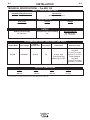
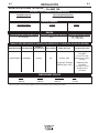
TECHNICAL SPECIFICATIONS – Pro-MIG 140
INPUT – SINGLE PHASE ONLY
Standard Voltage/Frequency
120V/60Hz
Input Current
20 Amps - Rated Output
RATED OUTPUT
Duty Cycle
20% Duty Cycle
Current
90 Amps
Voltage
19 V
OUTPUT
Welding Current Range
25-140 Amps
Maximum-Open Circuit Voltage
29V
Wire Speed Range
50 - 300 in/min.
(1.3 - 7.6 m/min.)
RECOMMENDED INPUT CABLE AND FUSE SIZES
Output Mode
RATED
Input Voltage
120V/60Hz
Fuse or
Breaker Size1
20 Amp
Input Amps
20
Power Cord
15 Amp, 125V,
Three Prong Plug
(NEMA Type 5-15P)
Extension Cord
Three Conductor
#14 AWG
(2.1 mm2) or Larger
Up to 25 Ft. (7.6 mm)
Three Conductor
#12 AWG
(3.3 mm2) or Larger
Up to 50 Ft. (15.2 mm)
PHYSICAL DIMENSIONS
Height
12.0 in
305 mm
1If
Width
9.75 in
248 mm
Depth
16.5 in
419 mm
connected to a circuit protected by fuses use Time Delay Fuse marked “D”.
Pro-MIG 140
Weight
48 Ibs
21.8 kg
A-2
A-2
INSTALLATION
Read entire installation section before starting
installation.
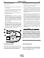
SAFETY PRECAUTIONS
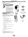
FIGURE A.1
WARNING
1
ELECTRIC SHOCK can kill.
• Only qualified personnel should perform
this installation.
• Only personnel that have read and understood the Pro-MIG 140 Operating Manual
should install and operate this equipment.
Pro-M
IG™
140
2
• Machine must be plugged into a receptacle
which is grounded per any national, local
or other applicable electrical codes.
4
• The Pro-MIG 140 power switch is to be in
the OFF (“O”) position when installing
work cable and gun and when connecting
power cord to input power.
3
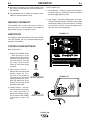
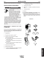
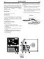
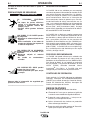
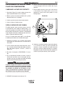
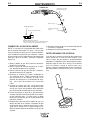
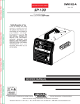
IDENTIFY AND LOCATE
COMPONENTS
6
If you have not already done so, unpack the Pro-MIG
140 from its carton and remove all packing material
around the Pro-MIG 140. Remove the following loose
items from the carton (see Figure A.1):
5
1. Pro-MIG 140
2. Gun and cable assembly(1)
7
8
3. Literature and miscellaneous including:
a) This operating manual
b) 3 extra .023"-.025” (0.6 mm) contact tips
c) 2 extra .035” (0.9 mm) contact tips
10
9
d) Hex key wrench for removal of drive roll.
4. 10 ft (3.0 m) work cable.
5. Work clamp.
6. a) 2lb. spool of .025” (0.6 mm) Super Arc L-56
MIG wire.
b) Sample spool of Innershield .035” (0.9 mm)
NR-211-MP.
7. Welding Helmet.
8. Adjustable mixed-Gas Regulator & Hose.
9. Instructional video.
10. Nozzle.
For available options and accessories refer to the
Accessories Section of this manual.
1)
As shipped from the factory, the Pro-MIG 140 gun
liner is ready to feed .023” (0.6 mm) -.035 (0.9 mm)
wire.
Pro-MIG 140
A-3
A-3
INSTALLATION
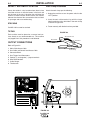
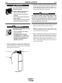
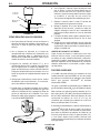
SELECT SUITABLE LOCATION
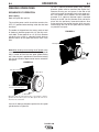
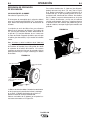
Work Clamp Installation
Locate the welder in a dry location where there is free
circulation of clean air into the louvers in the back and
out the front of the unit. A location that minimizes the
amount of smoke and dirt drawn into the rear louvers
reduces the chance of dirt accumulation that can block
air passages and cause overheating.
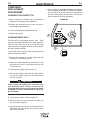
Attach the work clamp per the following:
1. Unplug the machine or turn the power switch to the
“OFF” position.
STACKING
2. Insert the work cable terminal lug with the larger
hole through the strain relief hole in the work clamp
as shown in Figure A-3.
Pro-MIG 140’s cannot be stacked.
3. Fasten securely with the bolt and nut provided.
TILTING
FIGURE A.3
Each machine must be placed on a secure, level surface, directly or on recommended cart. The machine
may topple over if this procedure is not followed.
Strain Relief Hole
Work Cable
Nut & Bolt
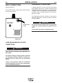
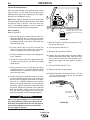
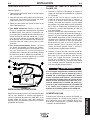
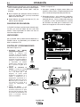
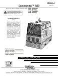
OUTPUT CONNECTIONS
Refer to Figure A.2.
1.
2.
3.
4.
5.
6.
7.
8.
Work Cable Access Hole.
Gun Cable and Control Lead Access Hole.
Connector Block.
Gun Trigger Lead Connectors.
Positive (+) and negative (–) output terminals.
Wire Feed Gearbox.
Cable Hanger.
Thumbscrew.
Work Clamp
4
5
DO NOT SWITCH
WHEN WELDING
+
Pro-MIG“ 140
8
-
3
1
2
FIGURE A.2
Pro-MIG 140
6
7
A-4
A-4
INSTALLATION
Work Cable Installation
Connecting Gun Cable to the Pro-MIG 140
Refer to Figure A.2.
1. Refer to Figure A.2. Unplug the machine or turn
power switch to the OFF “O” position.
1. Open the wire feed section door on the right side of
the Pro-MIG 140.
2. Pass the end of the work cable that has the terminal lug with the smaller hole through the Work
Cable Access Hole (1) in the case front.
3. Route the cable under and around the back of the
Wire Feed Gearbox (6).
4. For GMAW Only: Refer to Figure A.2. This is the
appropriate configuration for the GMAW (MIG)
process. To complete installation, use the provided
wing nut to connect the work cable’s terminal lug to
the negative (–) output terminal (5) located above
the Wire Feed Gearbox (6). Make sure that both
wing nuts are tight.
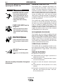
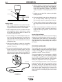
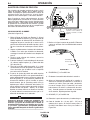
5. For Innershield Only: Refer to Figure A.4. As
delivered, the machine is connected for negative
electrode polarity. To wire for negative polarity
(required for the Innershield process), connect the
short cable attached to the connector block (1) to
the negative (–) output terminal (2) and the work
cable (3) to the positive (+) terminal (4).
2. Pass the insulated terminals of the gun trigger control leads, one at a time, through the Gun Cable
and Control Lead Access Slot (2) in the case front.
The leads are to be routed under the Wire Feed
Gearbox (6) and through the Cable Hanger (7) on
the inner panel.
3. Insert the connector on the gun conductor cable
through the Gun Cable Access Hole (2) in the ProMIG 140 case front. Make sure the connector is all
the way into the brass connector block. Unscrew
the thumbscrew on the connector block a few turns
if gun connector will not insert fully. Rotate the connector so control leads are on the underside and
tighten the Thumbscrew (8) in the connector block.
4. Connect the gun trigger control lead terminals to
the two insulated 1/4" (6.4 mm) tab terminal connector bushings located below the “Gun Trigger
Connection” decal in the wire feed section (4).
Either lead can go to either connector. Form the
leads so that they are as close as possible to the
inside panel.
CAUTION
4
3
2
1
If the gun trigger switch being used is other than
that supplied with the Pro-MIG 140, the switch
must be a normally open, momentary switch. The
terminals of the switch must be insulated from the
welding circuit. Malfunction of the Pro-MIG 140
may result if this switch shorts to the Pro-MIG 140
welding output circuit or is common to any electrical circuit other than the Pro-MIG 140 trigger circuit.
FIGURE A.4
GAS CONNECTION
GUN INSTALLATION
As shipped from the factory, the Pro-MIG 140 is ready
to feed .035" (0.9 mm) Innershield flux-cored wire. If
.023" – .025" (0.6 mm) solid wire is to be used, use
the appropriate contact tip , diffuser and Nozzle.
When using the GMAW process, a cylinder of shielding gas, must be obtained. For more information about
selecting gas cylinders for use with the Pro-MIG 140
refer to the ACCESSORIES section.
Pro-MIG 140
A-5
A-5
INSTALLATION
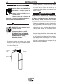
WARNING
CYLINDER may explode if damaged. Keep cylinder upright and
chained to support
2. With the cylinder securely installed, remove the
cylinder cap. Stand to one side away from the outlet and open the cylinder valve very slightly for an
instant. This blows away any dust or dirt which may
have accumulated in the valve outlet.
• Keep cylinder away from areas
where it may be damaged.
• Never lift welder with cylinder
attached.
• Never allow welding electrode to
touch cylinder.
• Keep cylinder away from welding
or other live electrical circuits.
WARNING
BE SURE TO KEEP YOUR FACE AWAY FROM
THE VALVE OUTLET WHEN “CRACKING” THE
VALVE. Never stand directly in front of or behind
the flow regulator when opening the cylinder
valve. Always stand to one side.
3. Attach the flow regulator to the cylinder valve and
tighten the union nut securely with a wrench.
WARNING
BUILDUP OF SHIELDING GAS may
harm health or kill.
• Shut off shielding gas supply
when not in use.
• SEE AMERICAN NATIONAL
STANDARD Z-49.1, “SAFETY IN
WELDING AND CUTTING” PUBLISHED BY THE AMERICAN
WELDING SOCIETY.
NOTE: If connecting to 100% CO2 cylinder, make
certain the plastic washer is seated in the fitting
that attaches to the CO2 cylinder.
4. Refer to Figure A.6. Attach one end of inlet gas
hose to the outlet fitting of the flow regulator and
tighten the union nut securely with a wrench.
Connect the other end to the Pro-MIG 140 Gas
Solenoid Inlet Fitting (5/8-18 female threads — for
CGA — 032 fitting). Make certain the gas hose is
not kinked or twisted.
1. Chain the cylinder to a wall or other stationary support to prevent the cylinder from falling over.
Insulate the cylinder from the work circuit and earth
ground. Refer to Figure A.5.
Cylinder Valve
Flow Regulator
Gas Hose
FIGURE A.5
Pro-MIG 140
A-6
A-6
INSTALLATION
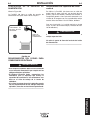
INPUT CONNECTIONS
Requirements For Rated Output
Refer to Figure A.6.
A power cord with a 15 amp, 125 volt, three prong
plug (NEMA Type 5-15P) is factory installed on the
Pro-MIG 140. Connect this plug to a mating grounded
receptacle which is connected to a 20 amp branch circuit with a nominal voltage rating of 115 to 125 volts,
60 Hertz, AC only.
The Pro-MIG 140 has a power input cable located on
the rear of the machine.
The rated output with this installation is 90 amps,19
Volts, 20% duty cycle (2 minutes of every 10 minutes
used for welding).
CAUTION
GAS SOLENOID
INLET FITTING
POWER INPUT
CABLE
Do not connect the Pro-MIG 140 to an input power
supply with a rated voltage that is greater than 125
volts.
Do not remove the power cord ground prong.
FIGURE A.6
CODE REQUIREMENTS FOR INPUT
CONNECTIONS
WARNING
This welding machine must be connected to a
power source in accordance with applicable electrical codes.
The National Electrical Code provides standards
for amperage handling capability of supply conductors based on duty cycle of the welding
source.
If there is any question about the installation
meeting applicable electrical code requirements,
consult a qualified electrician.
Pro-MIG 140
B-1
OPERATION
Read entire operation section before
operating the Pro-MIG 140.
WARNING
ELECTRIC SHOCK can kill.
• Do not touch electrically live
parts or electrode with skin or
wet clothing. Insulate yourself
from work and ground.
• Always wear dry insulating
gloves.
FUMES AND GASES can be
dangerous.
• Keep your head out of fumes.
• Use ventilation or exhaust to
remove fumes from breathing
zone.
B-1
GENERAL DESCRIPTION
The Pro-MIG 140 is a complete semiautomatic constant-voltage DC wire feeder / power source arc
welder. It has been designed for workshop, hobby,
automotive and light maintenance. Included is a tapswitch controlled, single phase constant voltage transformer / rectifier power source and a wire feeder welding gun for feeding .023 - .025” (0.6 mm) through
.030” (0.8 mm) solid steel electrode. An optional kit is
available for feeding .035” (0.9 mm) Innershield® NR211-MP flux-cored wire.
The Pro-MIG 140 is ideally suited for individuals having access to 120 volt AC input power, and wanting
the ease of use, quality and dependability of both gas
metal arc welding or GMAW (also known as MIG
welding) and the Innershield electrode process (self
shielded flux cored or FCAW). The Pro-MIG 140 is a
rugged and reliable machine that has been designed
for dependable service and long life.
RECOMMENDED PROCESSES
WELDING SPARKS can
cause fire or explosion.
• Keep flammable material away.
• Do not weld on closed containers.
The Pro-MIG 140 can be used for welding mild steel
using the Gas Metal Arc Welding (GMAW or MIG,
Metal Inert Gas) single pass process, which requires a
supply of shielding gas, or the flux-cored arc welding
(FCAW) process using Innershield® electrode wire.
The Pro-MIG 140 is configured for use with the FCAW
process as delivered from the factory.
OPERATIONAL CONTROLS
The Pro-MIG 140 has the following controls as standard: Control Power ON/OFF Switch, Voltage Control,
Wire Speed Control, Trigger Switch, and a Circuit
Breaker.
ARC RAYS can burn eyes
and skin.
• Wear eye, ear and body protection.
DESIGN FEATURES
● Operates on 120 volt input
● “Cold electrode” until gun trigger is pressed for an
added measure of safety.
● Overload protection — incorporates both a thermo-
stat and a circuit breaker.
Observe all safety information throughout
this manual.
● Quality wire drive with electronic overload protec-
tion.
● “Quick Release” idle roll pressure arm is easily
adjusted.
● Reversible, dual groove drive roll. Drive roll will
feed .023 – .025” (0.6 mm) and .030" - .035" (0.8 0.9 mm) diameter wire.
Pro-MIG 140
B-2
B-2
OPERATION
● No external shielding gas is required when used
with Lincoln Innershield .035” (0.9 mm) NR®-211MP electrode.
● Accommodates both 4” (100 mm) diameter and 8”
(200 mm) diameter spools of wire.
WELDING CAPABILITY
The Pro-MIG 140 is rated at 90 amps, 19 volts, at
20% duty cycle on a ten minute basis. It is capable of
higher output currents at lower duty cycles.
Refer to Figure B.1b.
4. Circuit Breaker – Protects machine from damage if
maximum output is exceeded. Button will extend
out when tripped (Manual reset).
5. Gun Trigger - Activates welding output, wire feed,
and gas solenoid operation. Releasing the trigger
deactivates welding and simultaneously activates
the “burnback” function so that the welding wire
does not stick in the weld puddle.
FIGURE B.1a
LIMITATIONS
Arc Gouging cannot be performed with the Pro-MIG
140. The Pro-MIG 140 is not recommended for pipe
thawing or TIG welding.
2
1
CONTROLS AND SETTINGS
3
Refer to Figure B.1a.
1. Control Power ON/OFF Switch
— When the power is on the
fan motor will run and air will be
exhausted out the louvers in the
front of the machine. The welding output and wire feeder
remain off until the gun trigger
is pressed.
2. Wire Speed Control —
Controls the wire feed speed
from 50 – 300 in /min. (1.3 –
7.6 m/min.). The control can
be preset on the dial to the
setting specified on the ProMIG 140 Application Chart
located on the inside of the
wire feed section door.
3. Voltage Control — A 4-position tap selector switch gives
full range adjustment of
power source output voltage.
Do not switch while welding
as damage to switch may
occur.
DO NOT SWITCH
WHEN WELDING
Pro-MIG™ 140
OFF
ON
WIRE SPEED
ARC VOLTS
Pro-MIG 140
FIGURE B.1b
B-3
B-3
OPERATION
WELDING OPERATIONS
SEQUENCE OF OPERATION
Wire Loading
Refer to Figures B.2 and B.3.
The machine power switch should be turned to the
OFF (“O”) position before working inside the wire feed
enclosure.
To use 4” (100 mm) diameter spools, the 2” (50 mm)
diameter spindle must be removed (See Figure B.3).
Remove the wing nut and spacer at the end of the
shaft and remove the outside plastic wire spool spindle. The spindle can be stored in the wire feed compartment. A 4” (100 mm) diameter spool is mounted
directly on the 5/8” (16 mm) diameter shaft and held in
place with the previously removed hardware. Also
make certain the start end of the wire, which may protrude through the side of the spool does not contact
any metallic case parts.
The welder is shipped from the factory ready to feed
8" (200 mm) diameter spools with 2.2" (56 mm) maximum width. These spools fit on a 2" (51 mm) diameter
spindle that has a built in, adjustable friction brake to
prevent overrun of the spool and excess slack in the
wire.
FIGURE B.3
4" Wire Spool
Wire Spindle Shaft
Note:When loading and removing the 8” Spools make
sure that the wing nut (inside the wire spool spindle
hub) is turned 90° from the wire spool spindle locking
tab. If the wing nut is positioned in line with the locking
tab, the tab cannot be depressed to load or unload the
wire spool.
FIGURE B.2
Wire Spool Spindle
8” Wire Spool
Be sure that this stud engages
the hole in the wire spool.
To Wire Drive
Wire Spool must be pushed all the way on the spindle so that the
spindles tab will hold it in place. The Wire Spool will rotate clockwise when wire is dereeled.
Load an 8” (200 mm) diameter spool on the wire spool
spindle shown in Figure B.2.
Pro-MIG 140
Wing Nut
and Spacer
To Wire Drive
B-4
B-4
OPERATION
Friction Brake Adjustment
With wire spool installed on the spindle shaft and the
wing nut loose, turn the spool by hand while slowly
tightening the wing nut until a light drag is felt. Tighten
the wing nut an additional 1/4 turn.
Note: When properly adjusted, the brake should provide only enough drag to prevent overrun of the spool
and excess slack in the wire. Too much drag may
result in wire feeding problems, and may cause premature wear of wire drive system components.
2
1
4
5
3
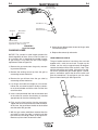
Wire Threading
Refer to Figure B.4
1. Release the Spring Loaded Pressure Arm (1)
rotate the Idle Roll Arm (2) away from. the Wire
Feed Drive Roll (3). Ensure that the groove size in
the feeding position on the drive roll matches the
wire size being used.
2. Carefully detach the end of the wire from the
spool. To prevent the spool from unwinding,
maintain tension on the wire until after step 5.
3. Cut the bent portion of wire off and straighten the
first 4” (100 mm).
4. Thread the wire through the In-going guide tube
(4), over the drive roll (3), and into the out-going
guide tube (5).
5. Close the idle roll arm (2) and latch the spring
loaded pressure arm (1) in place. Rotate the spool
counterclockwise if required in order to take up
extra slack in the wire.
6. The idle roll pressure adjustment wing nut is factory set to approximately five full turns from where
the wing nut first engages the threads of the pressure arm (1). If feeding problems occur because
the wire is flattened excessively, turn the pressure
adjustment counter-clockwise to reduce distortion
of the wire. Slightly less pressure may be required
when using 0.023 – 0.025" (0,6 mm) wire. If the
drive roll slips while feeding wire, the pressure
should be increased until the wire feeds properly.
The Wire Drive Feed Roll can
accommodate two wire sizes
by flipping the wire drive feed
roll over.
FIGURE B.4
7. Refer to Figure B.5. Remove gas nozzle and contact tip from end of gun.
8. Turn the Pro-MIG 140 ON (“I”).
9. Straighten the gun cable assembly.
10. Depress the gun trigger switch and feed welding
wire through the gun and cable. (Point gun away
from yourself and others while feeding wire.)
Release gun trigger after wire appears at end of
gun.
11. Turn the Pro-MIG 140 OFF (“O”).
12. Replace contact tip and gas nozzle.
13. Refer to Figure B-6. Cut the wire off 3/8” – 1/2” (10
– 13 mm) from the end of the tip. The Pro-MIG
140 is now ready to weld.
Gun Handle
Gas Diffuser/
Contact Tip
WARNING
Gas Nozzle
When inching the welding wire, the drive rolls, the
gun connector block and the gun contact tip are
electrically energized relative to work and ground
and remain energized for several seconds after
the gun trigger is released.
Pro-MIG 140
FIGURE B.5
B-5
OPERATION
B-5
6. Refer to Figure B.7. Connect work clamp to metal
to be welded. Work clamp must make good electrical contact to the workpiece. The workpiece
must also be grounded as stated in “Arc Welding
Safety Precautions” in the beginning of this manual.
Contact Tip
7. Position gun over joint. End of wire may be lightly
touching the work.
Wire Electrode
3/8"– 1/2"(10-13mm) Contact
Tip to Work Distance(CTWD)
8. Place hand shield in front of face, close gun trigger, and begin welding. Hold the gun so the contact tip to work distance is about 3/8 inch (10 mm).
FIGURE B.6
Making A Weld
1. See “Process Guidelines” in this section for selection of welding wire and shielding gas and for
range of metal thicknesses that can be welded.
2. See the Application chart on the inside of the wire
feed compartment door for information on setting
the Pro-MIG 140 controls. Refer to Table B.1 for
aluminum and stainless wire.
3. Set the Voltage (“V”) and Wire Speed (“olo’”) controls to the settings suggested for the welding wire
and base metal thickness being used, refer to
Applications chart on the inside of the wire drive
compartment door.
4. Check that the polarity is correct for the welding
wire being used and that the gas supply, if
required, is turned on.
5. When using Innershield electrode, remove the gas
nozzle and install the gasless nozzle. This will
improve visibility of the arc and protect the gas diffuser from weld spatter. Refer to the MAINTENANCE section for details on nozzle replacement.
9. To stop welding, release the gun trigger and then
pull the gun away from the work after the arc goes
out.
10. When no more welding is to be done, close valve
on gas cylinder (if used), momentarily operate gun
trigger to release gas pressure, and turn off the
Pro-MIG 140.
Cleaning Tip And Nozzle
Clean the contact tip and nozzle to avoid arc bridging
between the nozzle and contact tip which can result in
a shorted nozzle, poor welds and an overheated gun.
Hint: Anti-stick spray or gel, available from a welding
supply distributor, may reduce buildup and aid in spatter removal.
PROCESS GUIDELINES
The Pro-MIG 140 can be used for welding mild steel
using the GMAW, single pass process which requires
a supply of shielding gas or it can be used for the selfshielded, Innershield® process (FCAW).
The recommended gases and electrodes for GMAW
are welding grade CO2 gas or an argon-CO2 blended
gas (75 to 80% argon and 25 to 20% CO2) and .025"
(0.6 mm) diameter Lincoln Super Arc L-56 mild-steel
welding wire, supplied on 12-1/2 lb (5.7 kg) spools.
Pro-MIG™ 140
GUN CABLE
WORKPIECE
ARC
The recommended electrode for the self-shielded
process is .035” (0.9 mm) diameter Lincoln
Innershield® NR-211-MP. This electrode can be used
for all position welding of 20 gauge (1.0 mm) through
5/16" (8 mm) steel. Thickness of 1/4" (6 mm) and
5/16" (8 mm) require multiple passes. This wire can
also be used for the welding of galvanized coated
sheet metal.
WORK CLAMP
FIGURE B.7
Pro-MIG 140
B-6
OPERATION
The Pro-MIG 140 is suitable for .035" aluminum wire
and .030" stainless wire. Refer to Table B.1 for recommended procedure settings.
TABLE B.1
Process Welding Wire
Shielding
Gas
Voltage/Wire Speed
22 ga 16 ga 12 ga 1/8” 3/16” 1/4”
.035 Dia(0.9mm 100% Argon A-4.5 C-8.5 D-10 NR NR NR
4043 Aluminum
Wire
18 ga 16 ga 14 ga 12 ga 10ga
MIG DC+
.030 Dia
98% Argon/ B-6
308L Stainless 2% Oxygen
Steel Wire
C-6.5 D-7.5 NR
NR
B-6
2. If using a regulator with an adjustable flow meter,
close the gun trigger and adjust the flow to give 15
– 20 cubic ft per hour (CFH) (7 – 10 I/min.) [use 20
– 25 CFH (10 – 12 I/min.) when welding out of
position or in a drafty location for CO2]. For argon
mixed gas, trigger to release gas pressure, and
adjust the flow to give 25 – 30 CFH (12 – 14
I/min.).
3. Keep the cylinder valve closed, except when using
the Pro-MIG 140. When finished welding:
a) Close the cylinder valve to stop gas flow.
b) Depress the gun trigger briefly to release the
pressure in the gas hose.
NOTE:
NR - Not Recommended
c) Turn off the Pro-MIG 140.
CHANGING MACHINE OVER TO
FEED OTHER WIRE SIZES
WELDING WITH FCAW (Innershield)
The Pro-MIG 140 is shipped from the factory ready to
feed .035” (0.9 mm) diameter wire. To operate the
Pro-MIG 140 with other sizes of wire, it is necessary
to change the appropriate contact tip, diffuser, nozzle
and change the drive roll over to other sizes. Refer to
Changing the Contact Tip and Changing the Drive
Roll, in the MAINTENANCE section, for specific information on these procedures.
When using the FCAW process, the correct drive roll
and electrode polarity must be used. See Work Cable
Installation in INSTALLATION section for changing
the polarity.
OVERLOAD PROTECTION
Output Overload
The Pro-MIG 140 is equipped with a circuit breaker
and a thermostat which protects the machine from
damage if maximum output is exceeded. The circuit
breaker button will extend out when tripped. The circuit breaker must be manually reset.
WELDING WITH GMAW (MIG)
Shielding Gas
When using the GMAW process, the correct drive roll
and electrode polarity must be used. See Work Cable
Installation in INSTALLATION section for changing
the polarity.
When using the GMAW process, obtain and install a
gas regulator and hose kit. If using CO 2 a CO 2
adapter is required, sold separately.
1. For CO2, open the cylinder very slowly. For argonmixed gas, open cylinder valve slowly a fraction of
a turn. When the cylinder pressure gauge pointer
stops moving, open the valve fully.
Thermal Protection
The Pro-MIG 140 has a rated output duty cycle of
20%. If the duty cycle is exceeded, a thermal protector
will shut off the output until the machine cools to a
reasonable operating temperature. This is an automatic function of the Pro-MIG 140 and does not
require user intervention. The fan continues to run
during cooling.
Electronic Wire Drive Motor Protection
The Pro-MIG 140 has built-in protection for wire drive
motor overload.
Pro-MIG 140
B-7
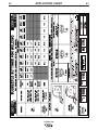
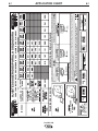
APPLICATION CHART
Pro-MIG 140
B-7
C-1
ACCESSORIES
OPTIONAL ACCESSORIES
1. K664-2 Aluminum Feeding Kit — This kit is recommended for welding with .035 Aluminum wire.
This kit may also be used for feeding .035 stainless
wire. Included with this kit are a drive roll, liner and
contact tip. It is important when changing
between welding with steel wire and aluminum
to exchange these components due to the
lubricant applied to steel wire. Failure to do so
may result in contaminated welds when welding aluminum.
2. K520 Utility Cart — Designed to transport the
Lincoln family of small welders. Has provisions for
mounting a single gas cylinder. Has front casters
and large rear wheels. Handle height is easily
adjustable. Bottom tray provided for tools and
accessories. Easy assembly required; takes less
than 15 minutes.
3. K586-1 Deluxe Adjustable Gas Regulator &
Hose Kit
Accommodates CO2 or mixed Gas Cylinders.
Pro-MIG 140
C-1
C-2
ACCESSORIES
INNERSHIELD (FCAW)
CONVERSION
REPLACEMENT PARTS
Several changes are needed to convert the unit for
operation with the Innershield (FCAW) process:
1. Change the output polarity to DC(–). See “Work
Cable Installation” in Installation section for details.
2. Install proper drive roll for the wire size selected.
See “Changing Drive Roll” in Maintenance section
for details.
3. Install the proper gun liner1 and tip for the wire size
selected. See “Component Replacement” in
Maintenance section for details.
4. Remove gas nozzle (if installed) and install the
gasless nozzle. To remove, simply unscrew.
5. Load wire into machine and thread into gun and
cable per “Welding Wire Loading” section.
Complete Gun and Cable Assembly
L8311-6 (K530-4)
Contact Tip .025” (0.6 mm)
KP2039-1B1
Contact Tip .030” (0.8 mm)
KP2039-2B1
Contact Tip .035” (0.9 mm)
KP2039-3B1
Contact Tip-Tapered .025” (0.6 mm)
KP2052-1B1
Contact Tip-Tapered .030” (0.8 mm)
KP2052-2B1
Contact Tip-Tapered .035” (0.9 mm)
KP2052-3B1
Liner .025 - .035” (0.6 - 0.9 mm)
KP1937-3
The factory installed gun liner will feed up to .035
(0.9mm) wire.
1
Gas Diffuser
KP2040-1
Gas Nozzle
KP1938-1
Gas Nozzle-Tip Recessed 3/8” (9.5 mm)
Opening I.D.
KP1942-1
Gas Nozzle-Tip Recessed 1/2” (12.7 mm)
Opening I.D.
KP1942-2
Gas Nozzle-Tip Recessed 5/8” (15.9 mm)
Opening I.D.
KP1942-3
Spot Welding Nozzle
KP1956-1
Gasless Nozzle (Innershield Only)
KP1939-1
Pro-MIG 140
C-2
D-1
MAINTENANCE
MAINTENANCE
SAFETY PRECAUTIONS
WARNING
ELECTRIC SHOCK can kill.
• Disconnect input power by removing
plug from receptacle before working
inside Pro-MIG 140. Use only grounded
receptacle. Do not touch electrically
“hot” parts inside Pro-MIG 140.
• Have qualified personnel do the maintenance and trouble shooting work.
ROUTINE MAINTENANCE
POWER SOURCE COMPARTMENT
No user serviceable parts inside! Do not attempt to perform
service in the power source (fixed) side of the Pro-MIG 140.
Take the unit to an authorized Lincoln Service Center if you
experience problems. NO maintenance is required.
In extremely dusty locations, dirt may clog the air passages
causing the welder to run hot with premature tripping of thermal protection. If so, blow dirt out of the welder with low pressure air at regular intervals to eliminate excessive dirt and dust
build-up on internal parts.
WIRE FEED COMPARTMENT
1. When necessary, vacuum accumulated dirt from gearbox
and wire feed section.
2. Occasionally inspect the incoming guide tube and clean
inside diameter if necessary.
3. Motor and gearbox have lifetime lubrication and require no
maintenance.
FAN MOTOR
Has lifetime lubrication — requires no maintenance.
WIRE REEL SPINDLE
Requires no maintenance. Do not lubricate shaft.
Pro-MIG 140
D-1
D-2
MAINTENANCE
GUN AND CABLE
MAINTENANCE
FOR MAGNUM™ 100L GUN
Gun Cable Cleaning
Clean cable liner after using approximately 300 lbs
(136 kg) of solid wire or 50 lbs (23 kg) of flux-cored
wire. Remove the cable from the wire feeder and lay it
out straight on the floor. Remove the contact tip from
the gun. Using low pressure air, gently blow out the
cable liner from the gas diffuser end.
CAUTION
Excessive pressure at the start may cause the dirt
to form a plug.
D-2
5. To remove gun tube from gun, remove gas nozzle
or gasless nozzle and remove diffuser from gun
tube. Remove both collars from each end of the
gun handle and separate the handle halves.
Loosen the locking nut holding the gun tube in
place against the gun end cable connector.
Unscrew gun tube from cable connector. To install
gun tube, screw the locking nut on the gun tube as
far as possible. Then screw the gun tube into the
cable connector until it bottoms. Then unscrew (no
more than one turn) the gun tube until its axis is
perpendicular to the flat sides of the cable connector and pointed in the direction of the trigger.
Tighten the locking nut so as to maintain the proper
relationship between the gun tube and the cable
connector. Replace the gun handle, trigger and diffuser. Replace the gas nozzle or gasless nozzle.
Flex the cable over its entire length and again blow
out the cable. Repeat this procedure until no further
dirt comes out.
Contact Tips, Nozzles, and Gun Tubes
1. Dirt can accumulate in the contact tip hole and
restrict wire feeding. After each spool of wire is
used, remove the contact tip and clean it by pushing a short piece of wire through the tip repeatedly.
Use the wire as a reamer to remove dirt that may
be adhering to the wall of the hole through the tip.
2. Replace worn contact tips as required. A variable
or “hunting” arc is a typical symptom of a worn contact tip. To install a new tip, choose the correct size
contact tip for the electrode being used (wire size is
stenciled on the side of the contact tip) and screw it
snugly into the gas diffuser.
3. Remove spatter from inside of gas nozzle and from
tip after each 10 minutes of arc time or as required.
4. Be sure the gas nozzle is fully screwed onto the
diffuser for gas shielded processes. For the
Innershield® process, the gasless nozzle should
be screws onto the diffuser.
Pro-MIG 140
D-3
D-3
MAINTENANCE
COMPONENT
REPLACEMENT
PROCEDURES
8. Push a length of straightened welding wire through
the wire feeder guide tubes and adjust the position
of the drive roll so that the groove is centered on
the wire. Make certain the set screw is located on
the flat portion of the shaft and tighten.
CHANGING THE CONTACT TIP
1. Refer to Figure D.2. Remove the gas nozzle from
the gun by unscrewing counter-clockwise.
FIGURE D.1
2. Remove the existing contact tip from the gun by
unscrewing counter-clockwise.
3. Insert and hand tighten desired contact tip.
4. Replace gas nozzle.
3
CHANGING DRIVE ROLL
The drive roll has two grooves; one for .023" – .025"
(0.6 mm) solid steel electrode and a larger groove for
.030" (0.8 mm) solid and .035" (0.9 mm) flux-cored
steel electrode. As shipped, the drive roll is installed in
the .035" (0.9 mm) position.
If .023"/.025" (0.6 mm) wire is to be used, the drive roll
must be reversed as follows:
1. Connect the machine to its rated input power per
instructions in Installation section.
2. Release the spring-loaded idle arm tensioner,Item 2, and
lift the idle roll arm, Item 3, away from the drive roll, Item
1. (See Figure D.1)
3. Turn the power switch to ON (marked “I”).
4. Set the wire speed to minimum and jog the drive
unit with the trigger switch until the drive roll set
screw is facing up.
CAUTION
When inching the welding wire, the drive rolls,
gun connector block, and gun contact tip are
energized relative to work and ground and remain
energized for several seconds after the gun trigger is released.
5. Turn the power switch to OFF (marked “O”).
6. Loosen the drive roll set screw with the 5/64" (2.0
mm) hex wrench supplied.
7. Remove the drive roll, flip over and reinstall with the
.023"/.025" (0.6 mm) groove (the smaller groove)
closest to the gearbox.
Pro-MIG 140
2
1
D-4
D-4
MAINTENANCE
1-1/4 (31.8 mm)
Liner Trim Length
Gas Diffuser
Set Screw
Brass Cable
Connector
Gas Nozzle or
Gasless Nozzle
Liner Assembly
(Liner bushing to be sealed tight
against brass cable connector)
FIGURE D.2
Liner trim length
8. Screw the gas diffuser onto the end of the gun tube
and securely tighten.
CHANGING LINER
9. Replace the contact tip and nozzle.
NOTICE: The variation in cable lengths prevents the
interchangeability of liners. Once a liner has been cut
for a particular gun, it should not be installed in another gun unless it can meet the liner cutoff length
requirement. Refer to Figure D.2.
1. Remove the gas nozzle from the gun by unscrewing counter-clockwise.
2. Remove the existing contact tip from the gun by
unscrewing counter-clockwise.
3. Remove the gas diffuser from the gun tube by
unscrewing counter-clockwise.
GUN HANDLE PARTS
The gun handle consists of two halves that are held
together with a collar on each end. To open up the
handle, turn the collars approximately 60 degrees
counter-clockwise until the collar reaches a stop. Then
pull the collar off the gun handle. If the collars are difficult to turn, position the gun handle against a corner,
place a screwdriver against the tab on the collar and
give the screwdriver a sharp blow to turn the collar
past an internal locking rib. See Figure D-3.
4. Lay the gun and cable out straight on a flat surface.
Loosen the set screw located in the brass connector at the wire feeder end of the cable. Pull the liner
out of the cable.
➣
5. Insert a new untrimmed liner into the connector end
of the cable. Be sure the liner bushing is stenciled
appropriately for the wire size being used.
Counter-clockwise
6. Fully seat the liner bushing into the connector.
Tighten the set screw on the brass cable connector.
At this time, the gas diffuser should not be installed
onto the end of the gun tube.
7. With the gas nozzle and diffuser removed from the
gun tube, be sure the cable is straight, and then
trim the liner to the length shown in the Figure D.2.
Remove any burrs from the end of the liner.
Pro-MIG 140
FIGURE D.3
E-1
TROUBLESHOOTING
E-1
HOW TO USE TROUBLESHOOTING GUIDE
WARNING
Service and Repair should only be performed by Lincoln Electric Factory Trained Personnel.
Unauthorized repairs performed on this equipment may result in danger to the technician and
machine operator and will invalidate your factory warranty. For your safety and to avoid Electrical
Shock, please observe all safety notes and precautions detailed throughout this manual.
__________________________________________________________________________
This Troubleshooting Guide is provided to help you
locate and repair possible machine malfunctions.
Simply follow the three-step procedure listed below.
Step 1. LOCATE PROBLEM (SYMPTOM).
Look under the column labeled “PROBLEM (SYMPTOMS)”. This column describes possible symptoms
that the machine may exhibit. Find the listing that
best describes the symptom that the machine is
exhibiting.
Step 3. RECOMMENDED COURSE OF ACTION
This column provides a course of action for the
Possible Cause, generally it states to contact your
local Lincoln Authorized Field Service Facility.
If you do not understand or are unable to perform the
Recommended Course of Action safely, contact your
local Lincoln Authorized Field Service Facility.
Step 2. POSSIBLE CAUSE.
The second column labeled “POSSIBLE CAUSE” lists
the obvious external possibilities that may contribute
to the machine symptom.
CAUTION
If for any reason you do not understand the test procedures or are unable to perform the tests/repairs safely, contact your
Local Lincoln Authorized Field Service Facility for technical troubleshooting assistance before you proceed.
Pro-MIG 140
E-2
E-2
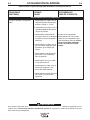
TROUBLESHOOTING
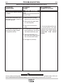
Observe all Safety Guidelines detailed throughout this manual
PROBLEMS
(SYMPTOMS)
POSSIBLE
CAUSE
RECOMMENDED
COURSE OF ACTION
OUTPUT PROBLEMS
Major physical or electrical damage
is evident.
None
Contact your local Authorized Field
Service Facility.
No wire feed, weld output or gas
flow when gun trigger is pulled. Fan
does NOT operate.
1. Make sure correct voltage is
applied to the machine (115vac).
2. Make certain that power switch
is in the ON position.
3. Make sure circuit breaker is
reset.
No wire feed, weld output or gas
flow when gun trigger is pulled.
Fan operates normally.
1. The thermostat may be tripped
due to overheating. Let machine
cool. Weld at lower duty cycle.
If all recommended possible areas
of misadjustment have been
checked and the problem persists,
Contact your local Lincoln
Authorized Field Service
Facility.
2. Check for obstructions in air
flow. Check Gun Trigger connections. See Installation section.
3. Gun trigger may be faulty.
CAUTION
If for any reason you do not understand the test procedures or are unable to perform the tests/repairs safely, contact your
Local Lincoln Authorized Field Service Facility for technical troubleshooting assistance before you proceed.
Pro-MIG 140
E-3
E-3
TROUBLESHOOTING
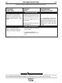
Observe all Safety Guidelines detailed throughout this manual
PROBLEMS
(SYMPTOMS)
POSSIBLE
CAUSE
RECOMMENDED
COURSE OF ACTION
FEEDING PROBLEMS
No wire feed when gun trigger is
pulled. Fan runs, gas flows and
machine has correct open circuit
voltage (32VDC maximum) – weld
output.
1. If the wire drive motor is running
make sure that the correct drive
rolls are installed in the machine.
2. Check for clogged cable liner or
contact tip.
3. Check for proper size cable liner
and contact tip.
If all recommended possible areas
of misadjustment have been
checked and the problem persists,
Contact your local Lincoln
Authorized Field Service
Facility.
GAS FLOW PROBLEMS
Low or no gas flow when gun
trigger is pulled. Wire feed, weld
output and fan operate normally.
1. Check gas supply, flow regulator
and gas hoses.
2. Check gun connection to
machine for obstruction or leaky
seals.
CAUTION
If for any reason you do not understand the test procedures or are unable to perform the tests/repairs safely, contact your
Local Lincoln Authorized Field Service Facility for technical troubleshooting assistance before you proceed.
Pro-MIG 140
E-4
E-4
TROUBLESHOOTING
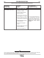
Observe all Safety Guidelines detailed throughout this manual
PROBLEMS
(SYMPTOMS)
POSSIBLE
CAUSE
RECOMMENDED
COURSE OF ACTION
WELDING PROBLEMS
Arc is unstable – Poor starting
1. Check for correct input voltage
to machine – 115vac.
2. Check for proper electrode
polarity for process.
3. Check gun tip for wear or damage and proper size – Replace.
4. Check for proper gas and flow
rate for process. (For MIG only.)
5. Check work cable for loose or
faulty connections.
If all recommended possible areas
of misadjustment have been
checked and the problem persists,
Contact your local Lincoln
Authorized Field Service
Facility.
6. Check gun for damage or
breaks.
7. Check for proper drive roll orientation and alignment.
8. Check liner for proper size.
CAUTION
If for any reason you do not understand the test procedures or are unable to perform the tests/repairs safely, contact your
Local Lincoln Authorized Field Service Facility for technical troubleshooting assistance before you proceed.
Pro-MIG 140
Pro-MIG 140
6 7 8 9 10
H2
N.O.
LS1
H1
T1
541
3
214
4
X1
X3
X4
X5
S2
SELECTOR
SWITCH
X2
209
2
J1
6
7
8
N.C. COMPONENT VIEWED FROM REAR.
N.D. BOLTED ALUMINUM CONNECTIONS
REQUIRE T12837 JOINT COMPOUND
(DOW CORNING 340) WHEN REATTACHING.
N.B. DIODES D1 & D3 ARE MOUNTED
ON THE INSIDE HEATSINK, WHICH
IS CLOSEST TO THE CENTER PANEL.
N.B.
202
D3
N.D.
D1
204
9 10
213
208
203
539
204
5
N.A. DIODES D2 & D4 ARE MOUNTED
ON THE OUTSIDE HEATSINK.
H1
CR1
1
CONTROL P.C. BOARD
LATCH
CAVITY NUMBERING SEQUENCE
( COMPONENT SIDE OF BOARD )
CASE
GROUNDING
STUD
H1
H2
H2
J1
1 2 3 4 5
115V/60HZ
GAS
SOLENOID
CIRCUIT
BREAKER
N.C.
TO EARTH GROUND PER
NATIONAL, LOCAL OR
OTHER APPLICABLE
ELECTRICAL CODES.
214
24V
AUXILIARY
WINDING
115V/60HZ
FAN MOTOR
F1
S1
ON-OFF
SWITCH
H2
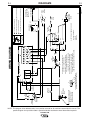
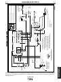
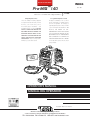
WIRING DIAGRAM
203
D4
N.D.
D2
204
204
+
209
LEAD COLOR CODE:
B-BLACK
W-WHITE
-
TO
WORK
+
(B)
(W)
-
DIAGRAMS
NOTE: This diagram is for reference only. It may not be accurate for all machines covered by this manual. The
specific diagram for a particular code is pasted inside the machine on one of the enclosure panels.
M20801
A
WIRE
FEED
MOTOR
GUN TRIGGER
GUN CABLE
CONDUCTOR
BLOCK
541
539
N.C.
ELECTRICAL SYMBOLS PER E1537
203
N.A.
203
213
OUTPUT
CHOKE
208
WIRE SPEED
5K
R2
THERMOSTAT
(MOUNTED TO
SEC. COIL)
Only qualified persons should install, use or service this machine.
Do not touch electrically live parts
Disconnect input power by unplugging power cord before servicing.
Do not operate with covers removed.
204
+ 59,000 f
C1
40V
203
HIGH VOLTAGE
can kill
WARNING
F-1
F-1
i
SEGURIDAD
ADVERTENCIA
La SOLDADURA POR ARCO puede ser peligrosa. PROTEJASE USTED Y A LOS DEMAS CONTRA POSIBLES LESIONES GRAVES O LA MUERTE. NO PERMITA QUE LOS NIÑOS SE ACERQUEN. LAS PERSONAS CON MARCAPASOS DEBEN CONSULTAR A SU MEDICO ANTES DE USAR ESTE EQUIPO.
Lea y entienda los siguientes mensajes de seguridad. Para más información acerca de la seguridad, se
recomienda comprar un ejemplar de "Safety in Welding & Cutting - ANIS Standard Z49.1" de la Sociedad
Norteamericana de Soldadura, P.O. Box 351040, Miami, Florida 33135 ó CSA Norma W117.2-1974. Una ejemplar gratis del folleto "Arc Welding Safety" (Seguridad de la soldadura al arco) E205 está disponible de Lincoln
Electric Company, 22801 St. Clair Avenue, Cleveland, Ohio 44117-1199.
ASEGURESE QUE TODOS LOS TRABAJOS DE INSTALACION, OPERACION, MANTENIMIENTO Y
REPARACION SEAN HECHOS POR PERSONAS CAPACITADAS PARA ELLO.
Para equipos ELECTRICOS.
1.a. Cortar la electricidad entrante usando el interruptor de desconexión en
la caja de fusibles antes de trabajar
en el equipo.
1.b. Instalar el equipo de acuerdo con el Código
Eléctrico Nacional (EE.UU.), todos los códigos
locales y las recomendaciones del fabricante.
1.c. Conectar a tierra el equipo de acuerdo con el
Código Eléctrico Nacional (EE.UU.) y las
recomendaciones del fabricante.
Los RAYOS DEL ARCO pueden quemar.
2.a. Colocarse una careta con el filtro y
cubiertas para protegerse los ojos de
las chispas y rayos del arco cuando
se suelde o se observe un soldadura
por arco abierta. El cristal del filtro y
casco debe satisfacer las normas
ANSI Z87.I.
2.b. Usar ropa adecuada hecha de material ignífugo
durable para protegerse la piel propia y la de los
ayudantes con los rayos del arco.
2.c. Proteger a otras personas que se encuentren
cerca con un biombo adecuado no inflamable y/o
advertirles que no miren directamente al arco ni
que se expongan a los rayos del arco o a las
salpicaduras o metal calientes.
LOS CAMPOS ELECTRICOS Y
MAGNETICOS
pueden ser peligrosos
3.a. La corriente eléctrica que circula por cualquiera de
los conductores causa campos eléctricos y magnéticos (EMF) localizados. La corriente para soldar
crea campos EMF alrededor de los cables y
máquinas soldadoras.
3.b. Los campos EMF pueden interferir con algunos
marcapasos, y los soldadores que tengan marcapaso deben consultar a su médico antes de manejar una soldadora.
3.c. La exposición a los campos EMF en soldadura
pueden tener otros efectos sobre la salud que se
desconocen.
3.d. Todo soldador debe emplear los procedimientos
siguientes para reducir al mínimo la exposición a
los campos EMF del circuito de soldadura:
3.d.1. Pasar los cables del electrodo y de trabajo
juntos - Atarlos con cinta siempre que sea
posible.
3.d.2. Nunca enrollarse el cable del electrodo
alrededor del cuerpo.
3.d.3. No colocar el cuerpo entre los cables del
electrodo y de trabajo. Si el cable del electrodo está en el lado derecho, el cable de
trabajo también debe estar en el lado derecho.
3.d.4. Conectar el cable de trabajo a la pieza de
trabajo lo más cerca posible del área que se
va a soldar.
3.d.5. No trabajar cerca del suministro eléctrico de
la soldadora.
MAR95
E S PA Ñ O L
i
ii
ii
SEGURIDAD
Las CHISPAS DE LA SOLDADURA
pueden causar incendio o
explosión.
El ELECTROCHOQUE puede
causar la muerte.
4.a. Quitar todas las cosas que presenten riesgo de
incendio del lugar de soldadura. Si esto no es
posible, cubrirlas para impedir que las chispas
de la soldadura inicien un incendio. Recordar
que las chispas y los materiales calientes de la
soldadura puede pasar fácilmente por las grietas pequeñas y aberturas adyacentes al área.
No soldar cerca de tuberías hidráulicas. Tener
un extinguidor de incendios a mano.
4.b. En los lugares donde se van a usar gases comprimidos, se deben tomar precauciones especiales para impedir las situaciones peligrosas.
Consultar la norma “Safety in Welding and
Cutting” (Norma ANSI Z49.1) y la información
de manejo para el equipo que se está usando.
4.c. No calentar, cortar o soldar tanques, tambores o
contenedores hasta haber tomado los pasos
necesario para asegurar que tales procedimientos no van a causar vapores inflamables o tóxicos de las sustancias en su interior. Pueden
causar una explosión incluso después de
haberse “limpiado”. Para información, comprar
“Recommended Safe Practices for the
Preparation for Welding and Cutting of
Containers and Piping That Have Held
Hazardous Substances”, AWS F4.1 de la
American Welding Society (ver la dirección más
arriba).
4.e. Ventilar las piezas fundidas huecas o contenedores antes de calentar, cortar o soldar. Pueden
explotar.
4.f. Las chispas y salpicaduras son lanzadas por el
arco de la soldadura. Usar vestimenta protectora libre de aceite tales como guantes de cuero,
camisa gruesa, pantalones sin bastillas, zapatos
de caña alta y un gorro. Ponerse tapones en los
oídos cuando se suelde fuera de posición o en
lugares confinados. Siempre usar gafas protectoras con escudos laterales cuando se esté en
un área de soldadura.
4.g. Conectar el cable de trabajo a la pieza de trabajo tan cerca del área de soldadura como sea
posible. Los cables de la pieza de trabajo
conectados a la estructura del edificio o a otros
lugares alejados del área de soldadura aumentan la posibilidad de que la corriente para soldar
pase por las cadenas de izar, cables de grúas u
otros circuitos alternativos. Esto puede crear
riesgos de incendio o sobrecalentar las cadenas
o cables de izar hasta hacer que fallen.
5.a. Los circuitos del electrodo y pieza de trabajo (o
tierra) están eléctricamente “vivos” cuando la soldadora está encendida. No tocar esas piezas “vivas”
con la piel desnuda o ropa mojada. Usar guantes
secos sin agujeros para aislar las manos.
5.b. Aislarse de la pieza de trabajo y tierra usando
aislante seco. Asegurarse que el aislante sea lo
suficientemente grande para cubrir toda el área de
contacto físico con la pieza de trabajo y el suelo.
Además de las medidas de seguridad normales,
si es necesario soldar en condiciones eléctricamente peligrosas (en lugares húmedos o mientras se está usando ropa mojada; en las estructuras metálicas tales como suelos, emparrillados o andamios; estando en posiciones apretujadas tales como sentado, arrodillado o acostado, si existe un gran riesgo de que ocurra contacto inevitable o accidental con la pieza de trabajo o tierra, usar el equipo siguiente:
• Soldadora (de alambre) de voltaje constante
CD semiautomática.
• Soldadora (de varilla) manual CD.
• Soldadora CA con control de voltaje
reducido.
5.c. En la soldadura con alambre semiautomática o
automática, el electrodo, carrete del electrodo,
cabezal soldador, boquilla o pistola para soldar
semiautomática también están eléctricamente
“vivas”.
5.d. Siempre asegurar que el cable de trabajo tenga
una buena conexión eléctrica con el metal que
se está soldando. La conexión debe ser lo más
cerca posible del área que se va a soldar.
5.e. Conectar la pieza de trabajo o metal que se va
a soldar a una buena tierra eléctrica.
5.f. Mantener el portaelectrodo, pinza de trabajo,
cable de la soldadora y la soldadora en condiciones de trabajo buenas y seguras. Cambiar el
aislante si está dañado.
5.g. Nunca sumergir el electrodo en agua para enfriarlo.
5.h. Nunca tocar simultáneamente la piezas eléctricamente “vivas” de los portaelectrodos conectados a dos soldadoras porque el voltaje entre los
dos puede ser el total del voltaje de circuito
abierto de ambas soldadoras.
5.i. Cuando se trabaje sobre el nivel del suelo, usar
un cinturón de seguridad para protegerse de
una caída si llegara a ocurrir electrochoque.
5.j. Ver también las partidas 4.c. y 1.
MAR95
iii
SEGURIDAD
Los HUMOS Y GASES
pueden ser peligrosos.
6.a. La soldadura puede producir humos y gases
peligrosos para la salud. No respirarlos.
Durante la soldadura, mantener la cabeza alejada de los humos. Tener bastante ventilación y/o
escape en el arco para mantener los humos y
gases lejos de la zona de respiración. Cuando
se suelde con electrodos que requieren ventilación especial tales como aceros inoxidables o revestimientos duros (ver las
instrucciones en el contenedor u hoja de
datos de seguridad del material, MSDS) o en
plomo o acero cadmiado y otros metales o
revestimientos que produzcan humos
hipertóxicos, mantener la exposición tan
baja como sea posible y por debajo de los
valores límites umbrales (TLV), utilizando un
escape local o ventilación mecánica. En
espacios confinados o en algunas situaciones, a la intemperie, puede ser necesario
el uso de un respirador. También se requiere
tomar otras precauciones adicionales cuando se suelda en acero galvanizado.
6.b. No soldar en lugares cerca de vapores de
hidrocarburo clorados provenientes de las
operaciones de desengrase, limpieza o pulverización. El calor y los rayos del arco puede
reaccionar con los vapores de solventes para
formar fosgeno, un gas hipertóxico, y otros productos irritantes.
6.c. Los gases protectores usados para la soldadura
por arco pueden desplazar el aire y causar
lesiones o la muerte. Siempre tener suficiente
ventilación, especialmente en las áreas confinadas, para tener la seguridad de que se respira aire fresco.
6.d. Leer y entender las instrucciones del fabricante
de este equipo y el material consumible que se
va a usar, incluyendo la hoja de datos de
seguridad del material (MSDS) y seguir las
reglas de seguridad del empleador, distribuidor
de material de soldar o del fabricante.
La BOTELLA de gas puede
explotar si está dañada.
7.a. Emplear únicamente botellas que contengan el
gas de protección adecuado para el proceso
utilizado, y reguladores en buenas condiciones
de funcionamiento diseñados para el tipo de
gas y la presión utilizados. Todas las
mangueras, rácores, etc. deben ser adecuados
para la aplicación y estar en buenas condiciones.
7.b. Mantener siempre las botellas en posición vertical sujetas firmemente con una cadena a la
parte inferior del carro o a un soporte fijo.
7.c. Las botellas de gas deben estar ubicadas:
• Lejos de las áreas donde puedan ser golpeados o estén sujetos a daño físico.
• A una distancia segura de las operaciones
de corte o soldadura por arco y de
cualquier fuente de calor, chispas o llamas.
7.d. Nunca permitir que el electrodo, portaelectrodo
o cualquier otra pieza con tensión toque la
botella de gas.
7.e. Mantener la cabeza y la cara lejos de la salida
de la válvula de la botella de gas cuando se
abra.
7.f. Los capuchones de protección de la válvula
siempre deben estar colocados y apretados a
mano, excepto cuando la botella está en uso o
conectada para uso.
7.g. Leer y seguir las instrucciones de manipulación
en las botellas de gas y el equipamiento asociado, y la publicación P-I de CGA, “Precauciones
para un Manejo Seguro de los Gases
Comprimidos en los Cilindros“, publicado por
Compressed Gas Association 1235 Jefferson
Davis Highway, Arlington, VA 22202.
MAR95
E S PA Ñ O L
iii
iv
iv
Gracias
para seleccionar un producto de CALIDAD por Lincoln eléctrica.
Quisiéramos que usted tomara orgullo en el funcionamiento de
este ••• del producto de Lincoln Electric Company tanto orgullo
como tenemos en traerle este producto!
Examine por favor el cartón y el equipo para el daño inmediatamente
Cuando se envía este equipo, título pasa al comprador sobre recibo por el portador. Por lo
tanto, las demandas para el material dañado en el envío se deben hacer por el comprador
contra la compañía del transporte cuando se recibe el envío.
Registre por favor su información de la identificación del equipo abajo para la referencia futura. Esta información se puede encontrar en su placa de identificación de la máquina.
Producto________________________________________________________________
Número De Model_________________________________________________________________
Número de serie_________________________________________________________________________
Fecha Comprada_________________________________________________________________________
Donde Comprado_______________________________________________________________________
Comprado siempre que usted solicite piezas o la información de recambio sobre este
equipo, provee siempre la información que usted ha registrado arriba. El número de código
es especialmente importante al identificar las piezas de recambio correctas.
Registro En línea Del Producto
- coloque su máquina con Lincoln eléctrica vía fax o excedente el Internet.
• para enviar por telefax: Llene el formulario en la parte posteriora de la declaración de la
garantía incluida en el paquete de la literatura que acompaña esta máquina y envíe por
telefax la forma por las instrucciones impresas en ella.
• Para El Registro En línea: Vaya a nuestro SITIO del WEB en www.lincolnelectric.com.
Elija los "acoplamientos rápidos" y entonces "registro del producto". Llene el formulario por favor y someta su registro.
Lea este manual de los operadores totalmente antes de procurar utilizar este equipo. Excepto este manual y
mantenga práctico para la referencia rápida. Atención particular de la paga a las instrucciones de seguridad que
hemos proporcionado para su protección. El nivel de la seriedad que se aplicará a cada uno se explica abajo:
ADVERTENCIA
La frase aparece cuando la información se debe seguir exactamente para evitar lesiones personales serias
o pérdida de la vida.
PRECAUCIÓN
Esta frase aparece cuando la información se debe seguir para evitar alguna lesión personal menor o daño a
este equipo
v
v
CONTENIDO PARA TODAS LAS SECCIONES
Page
De la Instalación ............................................................................................Sección A
Especificaciones Técnicas.....................................................................................A-1
Identifique y establezca los componentes .............................................................A-2
Seleccione La Localización Conveniente ..............................................................A-3
Conexiones De la Salida .......................................................................................A-3
Conexiones De la Entrada.....................................................................................A-6
Cifre Los Requisitos...............................................................................................A-6
Operación........................................................................................................Sección B
Medidas De Seguridad .........................................................................................B-1
Descripción General ..............................................................................................B-1
Características Del Diseño ....................................................................................B-1
Capacidad De la Soldadura...................................................................................B-2
Limitaciones...........................................................................................................B-2
Controles y ajustes ................................................................................................B-2
Operaciones De la Soldadura................................................................................B-3
Protección De la Sobrecarga.................................................................................B-6
Application Chart ...................................................................................................B-7
Accesorios ......................................................................................................Sección C
Accessories ...........................................................................................................C-1
Replacement Parts ................................................................................................C-2
Mantenimiento ................................................................................................Sección D
Medidas De Seguridad ..........................................................................................D-1
Artículos Que no requieren Ningún Mantenimiento...............................................D-1
Mantenimiento General .........................................................................................D-1
Mantenimiento del arma y del cable......................................................................D-2
Procedimientos Componentes Del Reemplazo.....................................................D-3
Trazador de líneas Que cambia ............................................................................D-4
Piezas De la Manija Del Arma...............................................................................D-4
Localización de averías .................................................................................Sección E
Medidas De Seguridad ..........................................................................................E-1
Cómo utilizar a guía de localización de averías ....................................................E-1
Guía De Localización de averías .........................................................E-2 THRU E-4
Digramas eléctricos........................................................................................Sección F
Digrama eléctrico ...................................................................................................F-1
E S PA Ñ O L
Listas de piezas....................................................................................P526 , P202-E.1
A-1
A-1
INSTALACIÓN
ESPECIFICACIONES TECNICAS – Pro-MIG 140
ENTRADA – SÓLO ALIMENTACIÓN MONOFÁSICA
Voltaje/Frecuencia
120V/60Hz
Corriente de Alimentación
20 Amps - Salida Clasificada
SALIDA NOMINAL
Corriente
90 Amps
Ciclo de Trabajo
20% Ciclo De Deber
Voltaje
19 V
SALIDA
Gama Actual Que suelda con autógena Ma'ximo-Abra El Voltaje Del Circuito Gama De la Velocidad Del Alambre
25-140 Amps
29V
50 - 300 in/min.
(1.3 - 7.6 m/min.)
TAMAÑOS RECOMENDADOS DE CABLES DE ALIMENTACIÓN Y FUSIBLES A UNA SALIDA NOMINAL
Fusible o
Modo De SalidaModo De Salida Triturador Size1 Amps de Ent.
CLASIFICADO
120V/60Hz
20 Amp
20
Cable de Energ.
Longitud del cable
Conductor Tres
#14 AWG
(2.1 mm2) o más
grande y has ta 25 Ft.
(7.6 mm)
15 Amp, 125V,
Enchufe De Tres Dientes
(NEMA Type 5-15P)
Conductor Tres
#12 AWG
(3.3 mm2) o más
grande y has ta
(15.2 mm)
DIMENSIONES FÍSICAS
Altrua
12.0 in
305 mm
Ancho
9.75 in
248 mm
Profundidad
16.5 in
419 mm
1 Si est?onectado con un circuito protegido por el uso de los fusibles retraso el?D marcado fusible?.
Pro-MIG 140
Peso
48 Ibs
21.8 kg
A-2
A-2
INSTALACIÓN
Lea todo el manual antes de iniciar la instalación
b) Carrete de la muestra del 0.9mm(.035")de
Innershield NR-211-MP.
7. Protector De la Mano.
PRECAUCIONES DE SEGURIDAD
8. Regulador y manguera ajustables del mezclarGas.
ADVERTENCIA
LA DESCARGA ELÉCTRICA puede
causar la muerte
• Únicamente el personal calificado
debe operar o instalar este equipo.
• Únicamente el personal que haya
leído y entendido el Manual de
Operación de la Pro-MIG 140 deberá
instalar y operar este equipo.
9. Vídeo educacional.
10. Nozzle.
Para las opciones disponibles y los accesorios refiera
a la sección de los accesorios de este manual.
1) Según lo enviado de la fábrica, el trazador de
líneas del arma Favorable-Pro-MIG 140 es listo alimentar el alambre 0.9mm(.035”) del 0.6 mm
(.023").
• La máquina debe conectarse a un receptáculo aterrizado de acuerdo con los códigos eléctricos aplicables nacionales, locales o de otro tipo.
• Al instalar el cable de trabajo y la antorcha, y cuando se conecte el cable de energía a la fuente de alimentación, el interruptor de encendido de la WeldPak deberá colocarse en la posición de “APAGADO” (“O”).
FIGURA A.1
1
---------------------------------------------------------------------------
IDENTIFIQUE Y UBIQUE LOS COMPONENTES
Pro-
MIG™
140
2
Si aún no lo ha hecho, desempaque la Pro-MIG 140
de su caja y retire todo el material del empaque de la
Pro-MIG 140. Retire las sigientes partes sueltas de la
caja (ver Figuras A.1):
4
3
1. Pro-MIG 140
6
2. Ensamble de la antorcha y cable (1)
5
3. Literature and miscellaneous including:
a) El manual de operación
b) 2 extremidades adicionales del contacto del
0.6mm(.023"-.025").
c) 3 extremidades adicionales del contacto del
0.9mm(035").
7
8
d) Llave de la llave de tuerca hexagonal para el
retiro del rodillo impulsor.
10
4. 3.0m(10 pies) cable del trabajo.
9
6. a) carrete de 0.91Kg(2lb.) del alambre estupendo
del arco L-56 MIG del 0.6mm(.025").
Pro-MIG 140
E S PA Ñ O L
5. Abrazadera del trabajo.
A-3
A-3
INSTALACIÓN
SELECCION DEL LUGAR ADECUADO
INSTALACION DE LA PINZA DE TRABAJO
Coloque la soldadora en un lugar seco y donde circule
aire limpio por las ventilas de la parte posterior y fuera
de la unidad. Un lugar donde se reduzca la cantidad de
humo y acumulación de polvo que pueden bloquear las
conductos
de
ventilación
y
ocasionar
sobrecalentamiento.
ESTIBACION
Coloque el cable en la pinza de trabajo de acuerdo con
lo siguiente:
1. Desconecte la máquina o gire el interruptor de
alimentación a la posición OFF (apagado).
2. Inserte el extremo de la terminal del cable de
trabajo a través del orificio de anclaje de la pinza
como se muestra en la Figura A-3.
3. Apriete con el tornillo o tuerca que se proporcionan.
La Pro-MIG 140’s no puede estibarse.
INCLINACION
FIGURA A.3
Cada máquina debe colocarse en una superficie plana
y segura ya sea directamente o sobre el soporte
recomendado. La máquina podría caerse de no seguir
este procedimiento.
Orificio de conexión
Cable De Trabajo
Tomilby Tuerca
CONEXIONES DE SALIDA
Refiera a la figura 2.a
Pirea de Trabajo
1. Orificio de entrada del cable de trabajo.
2. Orificio de entrada del Cable de Antorcha y Cable
de Control.
3. Bloque Conector.
4. Conectores para el Cable del Gatillo de la
Antorcha.
5. Terminales de Salida positiva (+) y negativa (-).
6. Caja de Engranajes de Alimentación de Alambre.
7. Gancho para Cable.
8. Tornillo mariposa.
4
5
DO NOT SWITCH
WHEN WELDING
+
Pro-MIG“ 140
8
-
3
1
2
FIGURE A.2
Pro-MIG 140
6
7
A-4
A-4
INSTALACIÓN
Conexión del Cable de la Antorcha a la
Pro-MIG 140
WORK CABLE INSTALLATION
Refer to Figure A.1
1. Open the wire feed section door on the right side of
the Pro-MIG 140
2. Pass the end of the work cable that has the terminal lug with the smaller hole through the Work
Cable Access Hole (1) in the case front.
3. Route the cable under and around the back of the
Wire Feed Gearbox (6).
4. Para GMAW Solamente: Refiera a la figura A.2.
Ésta es la configuración apropiada para el proceso
de GMAW (MIG). Para terminar la instalación, utilice la tuerca de ala proporcionada para conectar el
estirón terminal del cable del trabajo con (-) el terminal de salida negativo (5) situado sobre la caja
de engranajes de la alimentación del alambre (6).
Cerciórese de que ambas tuercas de ala sean
apretadas.
5. Para Innershield Solamente: Refiera a la figura
A.4. Según lo entregado, la máquina está conectada para la polaridad negativa del electrodo. Para
atar con alambre para la polaridad negativa
(requerida para el proceso de Innershield), conecte
el cable corto unido al bloque de conectador (1)
con (-) el terminal de salida negativo (2) y el cable
del trabajo (3) (+) al terminal positivo (4).
4
3
1. Consulte la Figura A.2. Desconecte la máquina o
coloque el interruptor de encendido en la posición
“O” (apagado).
2. Pase una por una las puntas aisladas de los
cables de control del gatillo de la antorcha, a
través de la Ranura de Acceso del Cable de
Control y del Cable de la Antorcha (2) en el frente
del gabinete. Los cables deberán pasar por debajo
de la Caja de Engranajes de Alimentación de
Alambre (6) y a través del Sujetador de Cable (7)
en el panel interno.
3. Inserte el conector del cable conductor de la antorcha a través del Orificio de Acceso del Cable de la
Antorcha (2), en el frente del gabinete de la WELDPAK 3200HD. Asegúrese de que el conector entre
totalmente en el bloque conector de latón. Si el
conector de la antorcha no entra por completo,
desenrosque un poco el tornillo mariposa del
bloque conector. Gire el conector para que los
cables de control queden abajo, y apriete el
Tornillo Mariposa (8) del bloque conductor.
4. Conecte las terminales del cable de control del
gatillo de la antorcha a los dos conectores aislados
de 6.4 mm (1/4”), que se localizan arriba de la etiqueta “Gun Trigger Connection” (Conexión del
Gatillo de la Antorcha) en la sección de alimentación de alambre (4). Cualquier cable puede
ir en cualquier conector. Acomode los cables lo
más cerca posible del panel interno.
2
PRECAUCION
Si el interruptor del gatillo de la antorcha se utiliza
con uno diferente al que se proporciona con la
Pro-MIG 140, el interruptor se debe abrir normalmente, interruptor momentáneo. Las terminales
del interruptor se deben aislar del circuito de soldadura. Si este interruptor hace corto con el circuito de soldadura de la Pro-MIG 140 podría ocasionarse un mal funcionamiento de la Pro-MIG 140
o ser común para cualquier circuito eléctrico
diferente al circuito del gatillo de la Pro-MIG 140.
------------------------------------------------------------------------
FIGURA A.4
INSTALACION DE LA ANTORCHA
Según lo enviado de la fábrica, el Favorable-Pro-MIG
140 es listo alimentar el alambre flujo-quitado el
corazo'n Innershield del 0.8-0.9 mm (.030-.035"). Si el
alambre sólido del 0.6 mm (.023"–.025") debe ser
utilizado, utiliza la extremidad, el difusor y el inyector
apropiados del contacto.
CONEXIÓN DE GAS
Cuando esten utilizando el proceso de GMAW, es
necesario obtener un cilindro de gas protector. Para
más información acerca de la selección de los cilindros de gas a utilizarse con la Pro-MIG 140 consulte
la sección de ACCESORIOS.
Pro-MIG 140
E S PA Ñ O L
1
A-5
ADVERTENCIA
Si el CILINDRO está dañado puede
explotar. Mantenga el cilindro en
posición vertical y encadenado para
que tenga soporte.
• Mantenga el cilindro alejado de
áreas donde pueda dañarse.
• Nunca levante la soldadora con el
cilindro en ella.
• Nunca permita que el electrodo de
soldadura toque el cilindro.
• Mantenga el cilindro alejado de soldaduras u
otros circuitos eléctricamente activos.
------------------------------------------------------------------------
ADVERTENCIA
La ACUMULACIÓN DE GAS
PROTECTOR puede afectar la salud
o causar la muerte.
• Interrumpa el suministro de gas
protector cuando no se utilice.
• VEA EL AMERICAN NATIONAL
STANDARD Z-49.1 (ESTÁNDAR
NACIONAL ESTADOUNIDENSE Z49.1), “SEGURIDAD EN LA
SOLDADURA Y EL CORTE”,
PUBLICADO POR LA AMERICAN
WELDING SOCIETY.
------------------------------------------------------------------------------------------
1. Encadene el cilindro a una pared o a un soporte
estático para evitar que caiga. Aísle eléctricamente
el cilindro del circuito de trabajo y de la conexión a
tierra. Véase Figura A.5.
2. Después de instalar el cilindro de manera segura,
retire la tapa. Muévase a un lado de la salida y
abra muy poco la válvula del cilindro por un
instante. Esto permite que el aire retire el polvo o
suciedad que pueda haberse acumulado en la salida de la válvula.
ADVERTENCIA
ASEGÚRESE DE MANTENER SU CARA RETIRADA DE LA SALIDA DE LA VÁLVULA AL “GIRARLA”. Nunca se coloque enfrente o detrás del regulador de flujo al abrir la válvula del cilindro.
Siempre párese a un lado.
----------------------------------------------------------------------3. Coloque el regulador de flujo en la válvula del cilindro y apriete bien la tuerca de unión con una llave.
NOTA: Si se conecta a un cilindro de CO 2 ,
asegúrese de que la arandela de plástico esta
colocada en el conector que se ensambla al cilindro de CO2.
4. Consulte la Figura A.6. Ensamble un extremo de la
manguera de gas de entrada al conector de salida
del regulador fluj\metro y apriete la tuerca de unión
con una herramienta. Conecte el otro extremo al
conector de entrada del Selenoide de Gas de ProMIG 140 (Rosca hembra de 5/8-18 para conector
CGA-032). Asegdrese de que la manguera de gas
no este machucada o doblada.
FIGURA A.5
Regulador
de Flujo
A-5
INSTALACIÓN
Válvula Del
Cilindro
Manguera
De Gas
Pro-MIG 140
A-6
A-6
INSTALACIÓN
CONEXIONES DE LA ENERGÍA DE
ALIMENTACIÓN
Requerimientos de capacidad de salida
nominal
Véase la Figura A.6.
De fábrica la Pro-MIG 140 viene con un cable de
energía de 15 amps, 125 volt, con enchufe de tres
puntas (Tipo 5-15P NEMA). Conecte este enchufe al
receptáculo gemelo a tierra que está conectado a un
circuito de 20 amperes con una capacidad de voltaje
nominal único de CA de 115 a125 voltios, 60 Hertz.
La Pro-MIG 140 tiene un cable de energía de
alimentación enla parte trasera de la máquina.
Con esta instalación, la la salida nominal es de 90
amps, 19, 20% de ciclo de trabajo (2 minutos de cada
10 de soldadura).
ADITAMENTO DE
ENTRADA DE GAS
SELENOIDE
GAS SOLENOID
INLET FITTING
PRECAUCION
CABLE DE
POWER
ENERGIA
DEINPUT
CABLE
ALIMENTACION
No conecte la Pro-MIG 140 a una alimentación de
voltaje mayor de 125v.
No retire la punta de tierra del enchufe del cable
de alimentación.
------------------------------------------------------------------------
FIGURA A.6
REQUERIMIENTOS DEL CODIGO PARA
CONEXIONES DE ENTRADA
ADVERTENCIA
Pro-MIG 140
E S PA Ñ O L
• Esta máquina soldadora deberá estar conectada
a una fuente de alimentación que cumpla con los
códigos eléctricos aplicables.
• El National Electrical Code proporciona los
estándares para el amperaje que maneja la
capacidad de suministro a los conductores con
base en el ciclo de trabajo de la fuente de
soldadura.
• Si no tiene la certeza de que la instalación cumple
con los requerimientos de los códigos eléctricos
aplicables, consulte un electricista especializado.
------------------------------------------------------------------------
B-1
OPERACIÓN
Lea todo el manual antes de instalar u operar la
Pro-MIG 140.
PRECAUCIONES DE SEGURIDAD
ADVERTENCIA
LA
DESCARGA
ELÉCTRICA
pADVERTENCIACIAmuerte
• No toque las partes eléctricas
activas ni el electrodo con ropa
mojada o húmeda. Aíslese del
trabajo y tierra.
• Siempre utilice guantes aislantes
secos.
LOS HUMOS Y LOS GASES pueden
ser peligrosos.
• Mantenga su cabeza alejada de los
vapores.
• Utilice ventilación o los tubos de
escape para eliminar los vapores de
la zona de respiración.
LAS CHISPAS DE LA SOLDADURA
pueden provocar un incendio o una
explosión.
• Mantenga alejado el material
flamable.
• No
suelde
en
contenedores
cerrados.
LAS CHISPAS DEL ARCO pueden
quemar los ojos y la piel.
• Utilice protección para ojos, orejas
y cuerpo.
Observe toda la información de seguridad que
aparece en este manual.
------------------------------------------------------------------------
B-1
DESCRIPCIÓN GENERAL
La Pro-MIG 140 es una soldadora por arco completa
con fuente de potencia/alimentador de alambre de CD
con voltaje constante semiautomático. Ha sido diseñada para trabajos en talleres, casas, automotora de
poco mantenimiento. Viene con un interruptor de
toma controlado, fuente de potencia para transformador/rectificador de voltaje constante de una sla
fase, y una antorcha de soldadura con alimentador de
alambre para alimentar electrodo de acero sólido de
0.6 mm (.023" - .025") hasta 0.8mm (.030"). Un juego
opcional está disponible para alimentación de electrodo revestido NR-211-MP Innershield.
La Pro-MIG 140 es ideal para aquellas personas que
tienen acceso a una energía de alimentación de CA
de 120 voltios, y desean que sea fácil de usar, de calidad y que pueda utilizarse con los procesos de
Soldadura de Arco Metálico con Gas o GMAW (también conocida como soldadura MIG), así como el proceso de electrodo Innershield (arco tubular autoprotegido o FCAW). La Pro-MIG 140 es una máquina rígida y confiable que ha sido diseñada para dar amplio
servicio y de larga vida útil.
PROCESOS RECOMENDADOS
La Pro-MIG 140 puede utilizarse para soldadura de
acero utilizando el proceso de una sola pasada de
Soldadura de Arco Metálico con Gas (GMAW o MIG,
Gas inherte de Metal), el cual requiere un suministro
de gas protector, o el proceso de soldadura de arco
tubular (FCAW) utilizando electrodo tubular
Innershield®. De fábrica, la Pro-MIG 140 está
configurada para utilizarse con el proceso FCAW .
CONTROLES DE OPERACION
Como estándar La Pro-MIG 140 tiene los siguientes
controles: Interruptor de ENCENDIDO/APAGADO
(ON/OFF) para control de energía, Control de Voltaje,
Control de Velocidad de Alambre, Interruptor del
Gatillo y un Interruptor de Circuito.
DESIGN FEATURES
● Funciona encendido entrada de 120 voltios
● “Electrodo frío” hasta que se presione el gatillo de
la antorcha como medida de seguridad adicional.
● Protección contra sobrecarga — incluye un ter-
mostato y un interruptor de circuito.
● Optima alimentación de alambre con protección
contra sobrecarga electrónica.
● Brazo de presión del rodillo impulsor de "liberación
rápida” que se ajusta de manera fácil.
Pro-MIG 140
B-2
B-2
OPERACIÓN
● Rodillo impulsor reversible con ranura de doble pro-
ceso. El rodillo impulsor alimentará alambre de 0.6
mm (.023 – .025”) y 0.8 - 0.9 mm (.030" - .035") de
diámetro.
● No se requiere gas protector externo cuando se
utiliza con electrodo .035” (0.9 mm) Innershield
NR®-211-MP de Lincoln.
● Acepta bobinas de alambre de 100 mm (4”) y de
200 mm (8”) de diámetro.
CAPACIDAD DE SOLDADURA
Refiera a la figura B.1b.
4. Interruptor - protege la máquina contra daño si se
excede la salida máxima. El botón extenderá hacia
fuera cuando está disparado (Reajuste Manual).
5. Disparador del arma - activa salida de la soldadura,
la alimentación del alambre, y la operación del
solenoide del gas. Lanzar el disparador desactiva
la soldadura y activa simultáneamente la función
del "burnback" de modo que el alambre de la soldadura no se pegue en el charco de la autógena.
La Pro-MIG 140 tiene capacidad nominal de 90 amps,
19 volts, con ciclo de trabajo del 20% cada diez
minutos. Tiene capacidades de salida más altas en
ciclos de trabajo más bajos.
FIGURA B.1a
LIMITACIONES
2
Con la Pro-MIG 140 no puede realizarse desbaste. La
Pro-MIG 140 no se recomienda para soldadura de
tubería o soldadura TIG.
1
3
CONTROLES Y PROGRAMACIONES
DO NOT SWITCH
WHEN WELDING
Consulte la Figura B.1a.
Pro-MIG 140
Pro-MIG™ 140
FIGURA B.1b
E S PA Ñ O L
1. Interruptor
de
ON/OFF
(ENCENDIDO/APAGADO)
—
Cuando
la
máquina
está
OFF
encendida, el motor del ventilador
comienza a funcionar y el aire es
expulsado por las ventilas que se
encuentran en la parte frontal de la
máquina. La salida de soldadura y
ON
el alimentador de alambre
permanecerán apagados hasta
que se presione el gatillo de la
antorcha.
2. Control de Velocidad de
Alambre — Controla la velocidad WIRE SPEED
de alimentación del alambre de
1.3 – 7.6 m/min (50 – 300
pulg/min). El control puede
programarse previamente en el
selector y establecerse en la
programación especificada en el
Diagrama de Aplicación de la ProMIG 140, que se localiza en la
cara interior de la puerta de la
sección de alimentación de
alambre.
ARC VOLTS
3. Control de Voltaje
— Un
interruptor selector de toma de 4
posiciones proporciona un ajuste
de rango total del voltaje de salida
de la fuente de alimentación. No
mueva el interruptor mientras
realiza una soldadura.
B-3
B-3
OPERACIÓN
SECUENCIA DE OPERACIÓN
DE SOLDADURA
COLOCACIÓN DEL ALAMBRE
Consulte las Figuras B.2 y B.3
El interruptor de encendido de la máquina deberá
estar en la posición de APAGADO (“O”), antes de trabajar dentro del compartimiento de alimentación de
alambre.
Para utilizar bobinas de 4" (100 mm) de diámetro,
deberá retirarse el eje de 2" (51 mm) (Ver la Figura
B.3). Retire el espaciador y la tuerca mariposa en el
extremo del eje. El eje se puede guardar en el compartimento del alimentador de alambre. Una bobina
de 4” (100mm) se monta directamente en el eje de
5/8” (16 mm) de diámetro y se fija con el hardware
retirado anteriormente. Asimismo, asegúrese de que
el extremo inicial del alambre, que puede salir por un
lado de la bobina, no toque ninguna parte metálica del
gabinete.
La máquina se envía de fábrica lista para alimentar
bobinas de 8" (200 mm) de diámetro. Una bobina de
2.2" (56 mm) de diámetro se monta directamente en
un eje de 2" (51 mm) de diámetro, el cual cuenta con
un freno de fricción integrado ajustable, que evita que
la bobina gire demasiado y haya exceso del alambre
suelto.
Nota: Al colocar y retirar las bobinas de 8" (200 mm)
asegúrese de que la tuerca mariposa (dentro del eje
de la bobina de alambre) haya sido girado 90° desde
el sujetador de la bobina de alambre. Si la tuerca
mariposa se coloca en línea con el sujetador, éste no
podrá presionarse para cargar o descargar la bobina
de alambre.
FIGURA B.2
Wire Spool Spindle
Bobina De Alambre
De 8”
Asegúrese de que este borne
entre en el orificio de la bobina
de alambre.
Al impulsor de
Alambre
La Bobina de Alambre deberá introducirse totalmente
en el eje para que la pestaña del mismo la sostenga
en su lugar. La Bobina de Alambre girará hacia la
derecha cuando el alambre se desenrede.
Colocar una bobina de 8” (200mm) en el eje del carrete como se muestra en la Figura B.2.
Pro-MIG 140
FIGURA B.3
Bobina de alambre
de 4”l
Eje Opcional
Tuerca mariposa
y espaciador
Al impulsor de
alambre
B-4
B-4
OPERACIÓN
AJUSTE DEL FRENO DE FRICCIÓN
Con la bobina de alambre instalada en el eje y con la
tuerca de mariposa aflojada, gire la bobina manualmente al tiempo que aprieta lentamente la tuerca de
mariposa hasta que se sienta un arrastre ligero.
Apriete la tuerca de mariposa 1/4 de vuelta adicional.
Nota: Cuando se ajusta adecuadamente, el freno
deberá proporcionar únicamente el arrastre suficiente
para evitar que la bobina gire y que el alambre tenga
holgura excesiva. Demasiado arrastre puede resultar
en problemas de alimentación del alambre y puede
ocasionar desgaste prematuro de los componentes
del sistema de alimentación de alambre.
2
1
4
5
3
El Rodillo Impulsor puede
ajustarse a dos calibres de
alambre volteando el rodillo
impulsor.
COLOCACION DEL ALAMBRE
(Consulte la figura B.4)
1. Retire el Brazo de Presión con Resorte (1). Gire el
Brazo del Rodillo de Presión (2), para separarlo del
Rodillo Impulsor de Alimentación de Alambre (3).
Asegúrese de que el tamaño de la muesca en la
posición de alimentación del rodillo impulsor, coincida con el tamaño de alambre que se está utilizando.
2. Separe cuidadosamente el extremo del alambre de
la bobina. Para evitar que la bobina se desenrolle,
mantenga la tensión del alambre hasta después del
paso 5.
3. Corte la parte saliente del alambre y estire los
primeros 100 mm (4”).
4. Inserte el alambre a través del tubo guía de entrada
(4), sobre el rodillo impulsor (3), y dentro del tubo
guía de salida (5).
5. Cierre el brazo del rodillo de presión (2) y ajuste
correctamente el brazo de presión con resorte (1).
Si es necesario, gire la bobina hacia la izquierda
para estirar más el alambre.
6. La tuerca de ajuste de presión del rodillo impulsor
está configurada de fábrica con aproximadamente 5
vueltas desde donde la tuerca recibe las vueltas del
brazo de presión (1). Si se presentan problemas de
alimentación debido a que el alambre se aplana
excesivamente, gire el ajuste de presión hacia la
izquierda para reducir la distorsión del alambre. Tal
vez se requiera un poco menos de presión al utilizar
alambre de 0.6 mm (0.023 – 0.025”). Si el rodillo
impulsor se mueve mientras se alimenta el alambre,
la presión deberá incrementarse hasta que la alimentación de alambre sea la adecuada.
FIGURA B.4
7. Refiera a la figura inyector de gas de B.5. Remove
y entre en contacto con la extremidad del extremo
del arma.
Gun Handle
Gas Diffuser/
Contact Tip
Gas Nozzle
FIGURA B.5
8. ENCIENDA (“I”) la Pro-MIG 140.
9. Enderece el ensamble del cable de la antorcha.
10. Aplane el interruptor del gatillo de la antorcha y
alimente el alambre de soldadura a través de la
antorcha y el cable. (Para que usted y los demás
no corran riesgos, dirija la antorcha hacia otro
lado mientras se realiza la alimentación de alambre). Cuando aparezca el alambre en el extremo
de la antorcha, deje de presionar el gatillo.
11. APAGUE (“O”) la Pro-MIG 140.
12. Reinstale la punta de contacto y la tobera de gas.
Cuando se desplaza alambre de soldadura, los
rodillos impulsores, el bloque conector de la
antorcha y la punta de contacto de la misma se
energizan eléctricamente en relación con el trabajo y la tierra, y permanecen energizados durante
varios segundos después de liberar el gatillo de la
antorcha.
------------------------------------------------------------------------
13. Corte el alambre 10 – 12 mm (3/8” – 1/2”) en el
extremo de la punta. Al finalizar estos pasos, la
Pro-MIG 140 deberá estar lista para soldar. la
Figura B.6.
Pro-MIG 140
E S PA Ñ O L
ADVERTENCIA
B-5
OPERACIÓN
6. Vea la Figura B.7. Conecte la pinza de trabajo al metal
que se soldará. La pinza de trabajo deberá tener un
buen contacto eléctrico con la pieza de trabajo.
Asimismo, la pieza de trabajo deberá aterrizarse, según
se establece al principio de este manual en
“Precauciones de Seguridad de la Soldadura por Arco”.
Punta de
Contacto
Electrodo de
Alambre
3/8"-1/2"(10-12mm) Extremidad
Del Contacto Para trabajar
Distance(CTWD)
FIGURA B.6
CÓMO REALIZAR UNA SOLDADURA
1. Vea "Instrucciones del Proceso" en esta sección para la
selección del alambre de soldadura y gas protector, así
como para el rango de grosor del metal que puede
soldarse.
2. Vea el diagrama de aplicación en el interior del
compartimiento del mecanismo de alimentación para
obtener información sobre la configuración de los
controles de la Pro-MIG 140. Consulte la Tabla B.1 para
alambre de aluminio y de acero inoxidable.
3. Programe los controles del Voltaje (“V”) y de la
Velocidad del Alambre (“olo”) conforme a los parámetros
que se sugieren para el alambre de soldadura y el
grosor de metal base que se están utilizando. Consulte
el diagrama de Aplicaciones que se encuentra en la cara
interior de la puerta del compartimiento del impulsor de
alambre.
4. Verifique que la polaridad sea correcta para el alambre
de soldadura que se está utilizando y, si es necesario,
que se este abierto el suministro de gas.
5. Cuando utilice un electrodo Innershield, retire la tobera
de gas e instale una tobera para soldadura sin gas. Esto
mejorará la visibilidad del arco y protegerá al difusor de
gas de las salpicaduras de la soldadura. Para mayor
información sobre cómo reemplazar la tobera, consulte
la sección de MANTENIMIENTO.
Pro-MIG™ 140
Cable de
la antorcha
Pieza de trabajo
Arco
Pinza de trabajo
B-5
7. Coloque la antorcha sobre la unión. El extremo del
alambre puede tocar ligeramente el trabajo.
8. Coloque el protector de la mano delante de la cara,
disparador cercano del arma, y comience a soldar con
autógena. Sostenga el arma así que la extremidad del
contacto para trabajar distancia es cerca de 10mm(3/8
pulgada).
9. Para dejar de soldar, libere el gatillo y después aleje la
antorcha del trabajo después de que el arco se haya
apagado.
10. Cuando no vaya a seguir soldando, cierre la válvula del
cilindro de gas (si utiliza uno), opere momentáneamente
el gatillo de la antorcha para liberar la presión del gas y
apague la Pro-MIG 140.
LIMPIEZA DE LA PUNTA Y LA TOBERA
Limpie la punta de contacto y la tobera para evitar arcos
eléctricos entre las mismas, ya que esto podría provocar
una tobera con corto, soldaduras deficientes y sobrecalentamiento de la antorcha. Sugerencia: Un rociador o gel antiadherente, disponible con los distribuidores de artículos de
soldadura, puede reducir la acumulación y ayudar a limpiar
las salpicaduras.
PROCESS GUIDELINES
La Pro-MIG 140 puede utilizarse para soldadura de acero
fundido utilizando el proceso GMAW, de una sola pasada
que requiere un suministro de gas protector o que se puede
utilizar para procesos Innershield® de electrodo
autorevestido (FCAW).
Los gases y electrodos recomendados para el GMAW son
gas de bióxido de carbono CO2 o gas de bióxido de carbono
CO2 mezclado con argón de grado de soldadura (de 75 a
80% argón y de 25 a 20% CO2) y alambre para soldadura de
0.6 mm (.025") de diámetro L-56 Lincoln Super Arc de acero
suministrado en bobinas de 12-1/2 lb (5.7 kg). Se
recomienda gas mezclado para soldadura en acero más
denso, por ejemplo calibre 14 (2.0 mm).
El electrodo recomendado para el proceso autorevestido es
Innershield® NR-211-MP de 0.9 mm (.035") de Lincoln en
bobinas de 4.5 kg (10 lb). Este electrodo se puede utilizar
para todas las posiciones de soldadura de calibre 20 (1.0
mm) hasta acero de 8 mm (5/16"). Un grosor de 6 mm (1/4")
y 8 mm (5/16") requiere varias pasadas. Asimismo, este
alambre también se puede utilizar para soldadura de hoja de
metal galvanizada.
Figura B.7
Pro-MIG 140
OPERACIÓN
La Pro-MIG 140 también es adecuada para alambre
de aluminio de 0.9 mm (0.035") y alambre inoxidable
de 0.8 mm (0.030"). Consulte la siguiente Tabla B.1
para conocer los parámetros del procedimiento
recomendado.
Proceso
Alambre De
la Soldadura
3. Mantenga la válvula del cilindro cerrada, excepto
cuando se utilice la Pro-MIG 140. Al terminar la
soldadura:
a) Cierre la válvula de gas para detener el flujo de
gas.
b) Oprima el gatillo de la pistola momentaneamente para liberar la presión en la manguera
de gas.
c) Apague la Pro-MIG 140.
Velocidad De Voltage/Wire
El blindar
Gas
22 ga 16 ga 12 ga 1/8” 3/16” 1/4”
.035 Dia(0.9mm 100% Argon A-4.5 C-8.5 D-10 NR NR
4043 Aluminum
Wire
18 ga 16 ga 14 ga 12 ga 10ga
MIG DC+
.030 Dia
98% Argon/ B-6
308L Stainless 2% Oxygen
Steel Wire
C-6.5 D-7.5 NR
NR
NR
NR-Not Recomendó
B-6
SOLDADURA CON FCAW
(Innershield)
Al utilizar el proceso FCAW, se deben utilizar el rodillo
impulsor y la polaridad de electrodo correcta. Véase
instalación del cable de Trabajo en la sección de
INSTALACION para cambiar la polaridad.
TABLA B.1
CÓMO CAMBIAR LA MÁQUINA PARA
ALIMENTAR OTROS TAMAÑOS DE
ALAMBRE
OVERLOAD PROTECTION
El Favorable-Pro-MIG 140 se envía de la fábrica lista
alimentar el alambre del diámetro del 0.9mm(.035”).
Para funcionar el Favorable-Pro-MIG 140 con otros
tamaños del alambre, es necesario cambiar la
extremidad apropiada del contacto, difusor, inyector y
cambiar el rodillo impulsor encima a otros tamaños.
Consulte la sección "Cómo cambiara la punta de contacto" y "Cómo cambiar el rodillo impulsor", en la sección de MANTENIMIENTO para conocer información
más específica sobre estos procedimientos.
SOLDADURA CON GMAW (MIG)
Gas Protector
Al usar el proceso de GMAW, el rodillo impulsor y la polaridad correctos del electrodo deben ser utilizados. Vea la
instalación de cable del trabajo en la sección de la instalación para cambiar la polaridad.
When using the GMAW process, obtain and install a gas
regulator and hose kit. If using 100% CO2 a CO2 adapter is
required, sold separately.
1. For CO2 , open the cylinder very slowly. For argonmixed gas, open cylinder valve slowly a fraction of a
turn. When the cylinder pressure gauge pointer stops
moving, open the valve fully.
Sobrecarga de Salida
La Pro-MIG 140 está equipada con un interruptor
automático y un termostato que protegen la máquina
de algún daño, en caso de que se exceda la salida
máxima. El botón del interruptor automático se activará cuando esto suceda. El interruptor automático
deberá restablecerse manual.
Protección térmica
La Pro-MIG 140 tiene un ciclo de trabajo de salida
nominal del 20%. Si se excede el ciclo de trabajo, un
protector térmico interrumpirá la salida hasta que la
máquina se enfríe y alcance una temperatura de
operación razonable. Esta es una función automática
de la Pro-MIG 140 y no requiere la intervención del
usuario. El ventilador seguirá funcionado durante el
enfriamiento.
Protección del Motor del Rodillo Impulsor
Electrónica
La Pro-MIG 140 cuenta con una protección integrada
en caso de que se presente una sobrecarga del motor
impulsor de alambre.
2. Si se utiliza un regulador con un medidor de flujo
ajustable, cierre el gatillo de la antorcha y ajuste el flujo
para dar de 15 – 20 pies cúbicos por hora (CFH) (7 –
10 I/min) [uso 20 – 25 CFH (10 – 12 I/min) al soldar
fuera de posición o en una ubicación expuesta a corrientes de aire para CO2]. Para argón mezclado con gas,
apriete el gatillo para liberar la presión de gas, y ajuste
el flujo hasta obtener de 25 – 30 CFH (12 – 14 I/min).
Pro-MIG 140
E S PA Ñ O L
B-6
ALAMBRE DE
ACERO SÓLIDO
ALAMBRE DE
ACERO SÓLIDO
ALAMBRE DE
LA SOLDADURA
Pro-MIG 140
PIEZAS DE LOS
MATERIALES
CONSUMIBLES DEL
ARMA Y DEL CABLE
Parte No.
Para El Tamaño Del Alambre
El Contacto Inclina - Deber Estándar
FLUJO - QUITADO
EL CORAZÓN
BLINDAR
EL GAS
ORIENTACIÓN DEL RODILLO IMPULSOR
SURCO
GRANDE
ALAMBRE DE ACERO SÓLIDO
SURCO
GRANDE
Parte No.
Para El Tamaño Del Alambre
Extremidades Del Contacto - Afiladas
Parte No.
Abertura I.D.
Inyector De Gas - Rubor De la Extremidad
Parte No.
Abertura I.D.
APPLICATION CHART
Parte No.
Difusor De Gases
Parte No.
Inyector De Gasless
ADVERTENCIA:
CUANDO LA FUENTE DE ENERGÍA DE LA SOLDADURA ESTÁ ENCENDIDO Y EL DISPARADOR DEL ARMA PRESIONADO,
LA ALIMENTACIÓN ROLLS, EL CARRETE DEL ALAMBRE Y EL ELECTRODO SON ELÉCTRICAMENTE CALIENTES.
Sea seguro leer y entender las advertencias en la máquina de soldadura y la sección en MEDIDAS de SEGURIDAD de la SOLDADURA de ARCO en el operating manual. Porque las
variables del diseño, de la fabricación, de la asamblea y de la soldadura afectan los resultados obtenidos en la aplicación de este tipo de información, el serviceablilty de un
producto o de una asamblea es la responsabilidad del builder/user.
Para el mejor funcionamiento instale
el trazador de líneas del 0.6mm/0.8mm
SURCO PEQUEÑO
(LADO BISELADO)
ALAMBRE DE ACERO SÓLIDO
FLUJO DE GASLESS - QUITADO EL CORAZÓN
ALINEE EL SURCO CON EL CENTRO DE LOS TUBOS DE GUÍA, RODILLO IMPULSOR SEGURO CON EL TORNILLO DE PRESIÓN CENTRADO EN PLANO
NINGUNOS
POLARIDAD DE LA SALIDA
PROCESO
GRUESO DE ACERO
PARA LOS AJUSTES DEL ACERO INOXIDABLE Y DEL ALUMINIO - VEA EL MANUAL
AJUSTES SUGERIDOS PARA LA SOLDADURA
B-7
B-7
C-1
ACCESORIOS
C-1
ACCESORIOS OPCIONALES
1. Juego de Alimentación de Aluminio K664-2 —
Este kit recomendado para soldar con autógena con
el alambre del aluminio del 035. También puede utilizarse para alimentación de alambre inoxidable de
.030. Incluye un rodillo impulsor, una guía de antorcha y una punta de contacto. Al cambiar de una alimentación de alambre de acero a una de aluminio, es importante que se intercambien los
componentes de la alimentación, debido al lubricante que se aplicó al alambre de acero. No hacerlo podría dar como resultado soldaduras contaminadas al soldar aluminio.
2. Carro multiusos K520 — Diseñado para transportar cualquier producto de la familia Lincoln de
soldadoras pequeñas. Tiene los aditamentos para
montar un cilindro de gas. Cuenta con ruedas más
grandes en la parte posterior. La manija de altura
puede ajustarse facilmente. Tiene una charola en
la parte inferior para colocar herramientas y accesorios. Su ensamble es sencillo y requiere menos
de 15 minutos.
Pro-MIG 140
E S PA Ñ O L
3. Estuche de regular de gas y manguera K586-1
ajustable de lujo - trabaja con cilindros de CO2 o
de gas mezclado.
C-2
ACCESORIOS
CONVERSIÓN DE INNERSHIELD (FCAW)
Varios cambios son necesarios convertir la unidad
para la operación con el proceso de Innershield
(FCAW):
1. Cambie la polaridad de la salida a DC(-). vea "la
instalación de cable del trabajo" en la sección de la
instalación para los detalles.
2. Instale el rodillo impulsor apropiado para el tamaño
del alambre seleccionado. Vea el "rodillo impulsor
que cambia" en la sección del mantenimiento para
los detalles.
3. Instale el arma apropiado liner1 e incline para el
tamaño del alambre seleccionado. Vea el "reemplazo componente" en la sección del mantenimiento
para los detalles.
4. Quite el inyector de gas (si está instalado) e instale
el inyector gasless. Para quitar, desatornille simplemente.
5. Cargue el alambre en la máquina y el hilo de rosca
en el arma y el cable por "la sección del cargamento del alambre de la soldadura".
El trazador de líneas instalado fábrica del arma alimentará hasta el alambre del 035 (0.9m m).
1
PARTES DE REEMPLAZO
Ensamble Completo de Antorcha y Cable
L8311-2 (K530-2)
Punta de Contacto 0.6 mm (.025”)
KP2039-1B1
Punta de Contacto 0.8 mm (.030”)
KP2039-2B1
Punta de Contacto 0.9 mm (.035”)
KP2039-3B1
Punta de Contacto Cónica 0.6 mm (.025”)
KP2052-1B1
Punta de Contacto Cónica 0.8 mm (.030”)
KP2052-2B1
Punta de Contacto Cónica 0.9 mm (.035”)
KP2052-3B1
Guía 0.8 - 0.9 mm (.030 - .035”)
KP1937-3
Difusor de Gas
KP2040-1
Tobera de Gas
KP1938-1
Tobera de Gas -Punta Retraída 9.5 mm (3/8”)
I.D. Abierta
KP1942-1
Tobera de Gas -Punta Retraída 12.7 mm (1/2”)
I.D. Abierta
KP1942-2
Tobera de Gas -Punta Retraída 15.9 mm (5/8”)
I.D. Abierta
KP1942-3
Tobera para Soldadura por Punteo
KP1956-1
Tobera (Sólo Innershield)
KP1939-1
Pro-MIG 140
C-2
MANTENIMIENTO
D-1
PRECAUCIONES DE SEGURIDAD
ADVERTENCIA
LA DESCARGA ELÉCTRICA puede causar
la muerte.
• Desconecte la energía de alimentación,
retirando la clavija del enchufe antes de
trabajar dentro de la Pro-MIG 140. Utilice
únicamente un enchufe aterrizado. No
toque las partes eléctricamente “activas"
dentro de la Pro-MIG 140.
• Sólo personal calificado deberá dar mantenimiento y realizar el trabajo de localización de averías.
-----------------------------------------------------------------------------------
MANTENIMIENTO DE RUTINA
COMPARTIMIENTO DE LA FUENTE
DE PODER
Dentro de la máquina no hay partes a las que el usuario
pueda dar servicio! No intente dar servicio al área de la fuente
de poder (fija) de la WELD-PAK 3200HD. Si se presentan
problemas, lleve la unidad a un Centro de Servicio Autorizado
de Lincoln. NO se requiere mantenimiento.
En localizaciones extremadamente polvorientas, la suciedad
puede estorbar los pasos de aire que hacen al soldador funcionar caliente con disparar prematuro de la protección termal. Si es así suciedad del soplo fuera del soldador con aire
de presión baja en los intervalos regulares para eliminar la
suciedad y la acumulación excesivas del polvo en piezas
internas.
COMPARTIMIENTO DE ALIMENTACIÓN DE ALAMBRE
1. Cuando sea necesario, elimine por aspiración la suciedad
acumulada en la caja de engranajes y en la sección de alimentación de alambre.
2. Revise periodicamente el tubo guía de entrada y limpie el
diámetro interno si es necesario.
3. El motor y la caja de engranajes tienen una lubricación de
por vida y no requieren mantenimiento.
MOTOR DEL VENTILADOR
Tiene una lubricación por vida — no requiere mantenimiento.
EJE DEL CARRETE DE ALAMBRE
No requiere mantenimiento. No aplique aceite en el eje.
Pro-MIG 140
E S PA Ñ O L
D-1
D-2
MANTENIMIENTO
MANTENIMIENTO
DE LA ANTORCHA Y EL CABLE
PARA ANTORCHA MAGNUMTM 100L
Limpieza del Cable de la Antorcha
Limpie la guía del cable después de utilizar aproximadamente 136 kg (300 lbs) de alambre sólido ó 23
kg (50 lbs) de alambre tubular autoprotegido. Retire
el cable del alimentador de alambre y estírelo sobre el
piso. Retire la punta de contacto de la antorcha.
Utilizando una presión baja, aplique aire suavemente
a la guía de alambre cable, en el extremo del difusor
de gas.
PRECAUCIÓN
Si se utiliza una presión excesiva al principio, la
suciedad puede acumularse.
-----------------------------------------------------------------------Estire el cable en toda su longitud y aplique aire otra
vez. Repita este procedimiento hasta que se elimine
totalmente la suciedad.
D-2
5. Pour enlever le tube du pistolet du pistolet, enlever la
buse de gaz ou la buse sans gaz et enlever le diffuseur
du tube du pistolet. Enlever les deux colliers de chaque
extrémité de la poignée du pistolet et séparer les moitiés
de la poignée. Desserrer l'écrou de blocage qui maintient le tube du pistolet contre le pistolet et le connecteur
de câble. Dévisser le tube du pistolet du connecteur de
câble. Pour monter le tube du pistolet, visser à fond
l'écrou de blocage sur le tube du pistolet. Puis visser le
tube du pistolet dans le connecteur de câble jusqu'à ce
qu'il soit bien enfoncé. Puis dévisser (un tour au maximum) le tube du pistolet jusqu'à ce que son axe soit perpendiculaire aux côtés plats du connecteur de câble en
direction de la gâchette. Serrer l'écrou de blocage pour
que le tube du pistolet et le connecteur du câble soient
bien en contact. Replacer la poignée du pistolet, la
gâchette et le diffuseur. Replacer la buse de gaz ou la
buse sans gaz.
Puntas de Contacto, Toberas y
Tubos de Antorcha
1. La suciedad puede acumularse en el orificio de la
punta de contacto, e interrumpir la alimentación de
alambre. Después de haber utilizado cada bobina
de alambre, retire la punta de contacto desatornillándola hacia la izquierda, y límpiela introduciendo
varias veces una pieza pequeña de alambre a
través de la punta. Utilice el alambre para remover
la suciedad que pueda estar adherida a las paredes del orificio de la punta.
2. Si es necesario, reemplace las puntas desgastadas. Un
arco variable o “inestable” es un síntoma típico de una
punta de contacto desgastada. Para instalar una nueva
punta, seleccione la punta de contacto con la medida
correcta para el electrodo que está utilizando (el tamaño
del alambre viene especificado a un lado de la punta de
contacto) y atorníllela en el difusor de gas.
3. Retire los residuos dentro de la tobera y de la punta
cada 10 minutos en que el arco esté encendido, o según
sea necesario.
4. Para los procesos con gas protector, asegúrese de que
la tobera de gas esté perfectamente atornillada en el
difusor. Para el proceso Innershield®, las toberas para
uso sin gas deben atornillarse en el difusor.
Pro-MIG 140
D-3
D-3
MANTENIMIENTO
PROCEDIMEINTOS PARA EL REEMPLAZO DE COMPONENTES
6. Afloje el tornillo de fijación del rodillo impulsor con
la llave hexagonal de 2.0 mm (5/64") que se proporciona.
CAMBIANDO LA PUNTA DE CONTACTO
7. Quite el rodillo impulsor, mueva de un tirón encima
y reinstálese con 0.6mm(.025") de un más
pequeño (el surco) lo más cerca posible a la caja
de engranajes.
1. Consulte la Figura D.2. retire la tobera de gas de la
pistola destornillándola hacia la izquierda.
FIGURA D.1
2. Retire la punta de contacto existente de la pistola
destornillando hacia la izquierda.
3. Inserte y apriete la punta de contacto deseada.
4. Vuelva a colocar la tobera de gas.
RODILLO IMPULSOR QUE CAMBIA
El rodillo impulsor cuenta con dos ranuras; una para
el electrodo de acero sólido de 0.6mm(.025") y un
surco más grande para el sólido y el 0.9mm(.035") del
0.8mm(.030") flujo-quitaron el corazo'n al electrodo de
acero. Según lo enviado, el rodillo impulsor está instalado en la posición del 0.9mm(.035").
3
2
1
Si se va el alambre del 0.9mm(.035") a ser utilizado,
el rodillo impulsor debe ser invertido como sigue:
1. Conecte la máquina con su energía de entrada
clasificada por instrucciones en la sección de la
instalación.
2. Lance el tensor ocioso por resorte del brazo, artículo 2, y levante el brazo ocioso del rodillo, artículo 3,
lejos del rodillo impulsor, artículo 1, (Véase La
Figura D.1)
8. Introduzca un pedazo recto de alambre de soldadura a través de los tubos guía del alimentador de
alambre y ajuste la posición del rodillo impulsor
para que la muesca quede centrada en el alambre.
Asegúrese de que el tornillo de fijación quede colocado en la parte plana del eje, y bien apretado.
3. Dé vuelta al interruptor a ENCENDIDO ("I" marcado).
4. Fije la velocidad del alambre al mínimo y active la
unidad de impulsión con el interruptor del disparador hasta que el tornillo de presión del rodillo
impulsor está haciendo frente para arriba.
Cuando el alambre de soldadura avanza unas pulgadas, los rodillos impulsores, el bloque conector
de la antorcha y la punta de contacto de la misma
se energizan en relación con el trabajo y el aterrizaje, y permanecerán así durante varios segundos después de que el gatillo se haya liberado.
-----------------------------------------------------------------------5. APAGUE el interruptor (marcado con “O”).
Pro-MIG 140
E S PA Ñ O L
ADVERTENCIA
D-4
D-4
MANTENIMIENTO
FIGURA D.2
Longitud de corte de la
guía 31.8 mm (1-1/4)
Difusor de gas
Tornillo de fijación
Tobera de gas/ Tobera
sin gas
Conector de latóndel cable
Asamblea del trazador de líneas
(buje del trazador de líneas que se sellará firmemente
contra el conectador de cobre amarillo del cable)
CAMBIO DE LA GUÍA DE ALAMBRE
NOTA: La variación en las longitudes del cable evitan
que se puedan intercambiar las guías. Una vez que
se haya cortado una guía para una antorcha determinada, no deberá instalarse en otra antorcha, a menos
de que cumpla con los requerimientos de longitud de
corte de la guía de alambre. Consulte la siguiente
Figura D.2.
PARTES DE MANEJO DE ANTORCHA
La manija de la antorcha consiste de dos mitades que
están unidas con un collar en cada extremo. para
abrir la manija, gire los collares a aproximadamente
60 grados a la izquierda hasta que encuentre un tope.
después saque el collar de la manija. Si se dificulta
girar los collares, colque la manija contra una
esquina, colque el destornillador contra una pestaña
del desarmador y presione hasta sacar. Ver Figura
D.3.
Pro-MIG 140
➣
1. Retire la tobera de gas de la antorcha, desatornillando hacia la izquierda.
2. Retire la punta de contacto existente en la antorcha, desatornillando hacia la izquierda.
3. Retire el difusor de gas del tubo de la antorcha,
desatornillando hacia la izquierda.
4. Descanse la antorcha y el cable y colóquelos en
una superficie plana. Afloje el tornillo de fijación
que se localiza en el conector de latón, en el
extremo del cable que va al alimentador de alambre. Jale la guía de alambre hacia afuera del
cable.
5. Inserte una nueva guía sin cortar dentro del
extremo del conector del cable. Asegúrese de que
el buje de la guía esté grabado adecuadamente
para el tamaño de alambre que se está utilizando.
6. Inserte totalmente el buje de la guía dentro del
conector. Apriete el tornillo de fijación en el conector del cable de latón. En este punto, no debe
instalarse el difusor de gas en el otro extremo del
tubo de la antorcha.
7. Después de haber retirado la tobera de gas y el
difusor del tubo de la antorcha, asegúrese de que
el cable esté recto, y después corte la guía a la longitud que se muestra en la siguiente figura D.2.
Retire cualquier sobrante del extremo de la guía de
alambre.
8. Atornille el difusor de gas en el extremo del tubo de
la antorcha y asegúrelo.
9. Reemplace la punta de contacto y la tobera.
A la izquierda
FIGURA D.3
E-1
LOCALIZACIÓN DE AVERÍAS
E-1
CÓMO UTILIZAR A GUÍA DE LOCALIZACIÓN DE AVERÍAS
ADVERTENCIA
El servicio y la reparación se deben realizar solamente por el personal entrenado fábrica eléctrica de
Lincoln. Las reparaciones desautorizadas realizadas en este equipo pueden dar lugar a peligro al
técnico y al maquinista e invalidarán su garantía de la fábrica. Para su seguridad y evitar choque
eléctrico, observe por favor todas las notas y precauciones de seguridad detalladas a través de este
manual.
__________________________________________________________________________
Esta guía de localización de averías se proporciona
para ayudarle a localizar y a reparar malfuncionamientos posibles de la máquina. Siga simplemente el procedimiento three-step enumerado abajo.
Paso 1. LOCALICE EL PROBLEMA (SÍNTOMA).
Mire debajo de la columna etiquetada "PROBLEMA
(SÍNTOMAS)". Esta columna describe los síntomas
posibles que la máquina puede exhibir. Encuentre el
listado que describe lo más mejor posible el síntoma
que la máquina está exhibiendo.
Paso 3. LÍNEA DE CONDUCTA RECOMENDADA
Esta columna proporciona una línea de conducta para
la causa posible, él los estados para entrar en contacto con generalmente su facilidad autorizada Lincoln
local del servicio de campo.
Si usted no entiende ni no puede realizar la línea de
conducta recomendada con seguridad, entre en contacto con su facilidad autorizada Lincoln local del servicio de campo.
Paso 2. CAUSA POSIBLE.
La segunda columna etiquetó las listas de la "CAUSA
POSIBLE" las posibilidades externas obvias que
pueden contribuir al síntoma de la máquina.
Si por ninguna razón usted no entiende los métodos de prueba ni no puede realizar el tests/repairs con seguridad, entre en
contacto con su Lincoln local autorizada facilidad del servicio de campo para la ayuda de localización de averías técnica
antes de que usted proceda.
Pro-MIG 140
E S PA Ñ O L
PRECAUCIÓN
E-2
LOCALIZACIÓN DE AVERÍAS
E-2
Observe todas las pautas de seguridad detalladas a través de este manual
PROBLEMAS
(SÍNTOMAS)
POSIBLE
CAUSA
RECOMENDADO
LÍNEA DE CONDUCTA
PROBLEMAS DE LA SALIDA
El daños física o eléctrica importante es evidente.
Ninguno Entre en contacto con su
facilidad autorizada local del servicio de campo.
Ninguna alimentación del alambre,
salida de la autógena o flujo del
gas cuando se tira el disparador del
arma. El ventilador no funciona.
1. Cerciórese de que el voltaje correcto esté aplicado a la máquina
(115vac).
2. Asegúrese que el interruptor
esté en la posición de trabajo.
3. Cerciórese de que el interruptor
esté reajustado.
Ninguna alimentación del alambre,
salida de la autógena o flujo del
gas cuando se tira el disparador del
arma. Aviente funciona normalmente.
1. El termóstato puede ser disparado debido al recalentamiento.
Deje la máquina fresca. Suelde
con autógena en un ciclo de
deber más bajo.
Si todas las áreas posibles
recomendadas de la mala regulación se han comprobado y persiste el problema, entre en contacto con su facilidad autorizada
Lincoln local del servicio de
campo.
2. Compruebe para saber si hay
obstrucciones en flujo de aire.
Compruebe las conexiones del
disparador del arma. Vea la sección de la instalación.
3. El disparador del arma puede
ser culpable.
PRECAUCIÓN
Si por ninguna razón usted no entiende los métodos de prueba ni no puede realizar el tests/repairs con seguridad, entre en
contacto con su Lincoln local autorizó la facilidad del servicio de campo para la ayuda de localización de averías
técnica antes de que usted proceda.
Pro-MIG 140
LOCALIZACIÓN DE AVERÍAS
E-3
E-3
Observe todas las pautas de seguridad detalladas a través de este manual
PROBLEMAS
(SÍNTOMAS)
POSIBLE
CAUSA
RECOMENDADO
LÍNEA DE CONDUCTA
PROBLEMAS DE ALIMENTACIÓN
Ninguna alimentación del alambre
cuando se tira el disparador del
arma. El ventilador funciona, el gas
fluye y la máquina tiene voltaje correcto del circuito abierto (máximo
32VDC) - suelda con autógena salida.
1. Si el motor impulsor del alambre
está funcionando cerciórese de
que los rodillos impulsores correctos estén instalados en la
máquina.
2. Compruebe para saber si hay el
trazador de líneas estorbado del
cable o entre en contacto con la
extremidad.
3. Compruebe para saber si hay el
trazador de líneas apropiado del
cable del tamaño y entre en contacto con la extremidad.
PROBLEMAS
(SÍNTOMAS)
POSIBLE
CAUSA
Si todas las áreas posibles
recomendadas de la mala regulación se han comprobado y persiste el problema, entre en contacto con su facilidad autorizada
Lincoln local del servicio de
campo.
RECOMENDADO
LÍNEA DE CONDUCTA
PROBLEMAS DEL FLUJO DEL GAS
1. Compruebe la fuente de gas,
fluya regulador y las mangueras
del gas.
2. Compruebe la conexión del arma
a la máquina para saber si hay
obstrucción o sellos agujereados.
Si todas las áreas posibles
recomendadas de la mala regulación se han comprobado y persiste el problema, entre en contacto con su facilidad autorizada
Lincoln local del servicio de
campo.
PRECAUCIÓN
Si por ninguna razón usted no entiende los métodos de prueba ni no puede realizar el tests/repairs con seguridad, entre en
contacto con su Lincoln local autorizó la facilidad del servicio de campo para la ayuda de localización de averías
técnica antes de que usted proceda.
Pro-MIG 140
E S PA Ñ O L
Punto bajo o ningún flujo del gas
cuando se tira el disparador del
arma. La alimentación del alambre,
la salida de la autógena y el ventilador funcionan normalmente.
LOCALIZACIÓN DE AVERÍAS
E-4
E-4
Observe todas las pautas de seguridad detalladas a través de este manual
PROBLEMAS
(SÍNTOMAS)
POSIBLE
CAUSA
RECOMENDADO
LÍNEA DE CONDUCTA
PROBLEMAS DE LA SOLDADURA
El arco es inestable - el comenzar
pobre
1. Compruebe para saber si hay el
voltaje de entrada correcto para
trabajar a máquina - 115vac.
2. Compruebe para saber si hay la
polaridad apropiada del electrodo para el proceso.
3. Compruebe la extremidad del
arma para saber si hay desgaste
o el daños y tamaño apropiado substituya.
4. Compruebe para saber si hay el
gas y el caudal apropiados para
el proceso. (para el MIG solamente.)
Si todas las áreas posibles
recomendadas de la mala regulación se han comprobado y persiste el problema, entre en contacto con su facilidad autorizada
Lincoln local del servicio de
campo.
5. Compruebe el cable del trabajo
para saber si hay conexiones
flojas o culpables.
6. Compruebe el arma para saber
si hay daño o roturas.
7. Compruebe para saber si hay la
orientación apropiada y alineación del rodillo impulsor.
8. Compruebe el trazador de líneas
para saber si hay el tamaño
apropiado.
PRECAUCIÓN
Si por ninguna razón usted no entiende los métodos de prueba ni no puede realizar el tests/repairs con seguridad, entre en
contacto con su Lincoln local autorizó la facilidad del servicio de campo para la ayuda de localización de averías
técnica antes de que usted proceda.
Pro-MIG 140
6 7 8 9 10
H2
N.O.
H1
T1
541
2
3
214
4
X1
X3
X4
X5
S2
SELECTOR
SWITCH
X2
209
1
6
7
8
N.C. COMPONENT VIEWED FROM REAR.
N.D. BOLTED ALUMINUM CONNECTIONS
REQUIRE T12837 JOINT COMPOUND
(DOW CORNING 340) WHEN REATTACHING.
N.B. DIODES D1 & D3 ARE MOUNTED
ON THE INSIDE HEATSINK, WHICH
IS CLOSEST TO THE CENTER PANEL.
N.B.
202
D3
N.D.
D1
204
9 10
213
208
203
539
204
5
N.A. DIODES D2 & D4 ARE MOUNTED
ON THE OUTSIDE HEATSINK.
H1
CR1
LATCH
CAVITY NUMBERING SEQUENCE
( COMPONENT SIDE OF BOARD )
CASE
GROUNDING
STUD
H1
J1
1 2 3 4 5
115V/60HZ
GAS
SOLENOID
CIRCUIT
BREAKER
N.C.
H2
LS1
J1
203
D4
N.D.
D2
204
204
+
209
LEAD COLOR CODE:
B-BLACK
W-WHITE
-
TO
WORK
+
(B)
(W)
-
M20801
A
WIRE
FEED
MOTOR
GUN TRIGGER
GUN CABLE
CONDUCTOR
BLOCK
541
539
N.C.
ELECTRICAL SYMBOLS PER E1537
203
N.A.
203
213
OUTPUT
CHOKE
208
WIRE SPEED
5K
R2
THERMOSTAT
(MOUNTED TO
SEC. COIL)
Only qualified persons should install, use or service this machine.
Do not touch electrically live parts
Disconnect input power by unplugging power cord before servicing.
Do not operate with covers removed.
204
+ 59,000 f
C1
40V
203
HIGH VOLTAGE
can kill
WARNING
DIGRAMA ELÉCTRICO
NOTA: Este diagrama está para la referencia solamente. Puede no ser exacto para todas las máquinas cubiertas
por este manual. El diagrama específico para un código particular se pega dentro de la máquina en uno de los
paneles del recinto.
E S PA Ñ O L
Pro-MIG 140
TO EARTH GROUND PER
NATIONAL, LOCAL OR
OTHER APPLICABLE
ELECTRICAL CODES.
214
24V
AUXILIARY
WINDING
115V/60HZ
FAN MOTOR
F1
S1
ON-OFF
SWITCH
H2
H2
CONTROL P.C. BOARD
WIRING DIAGRAM
F-1
F-1
NOTAS
Pro-MIG 140
NOTES
PRO-MIG 140
NOTES
PRO-MIG 140
NOTES
PRO-MIG 140
● Do not touch electrically live parts or
WARNING
Spanish
AVISO DE
PRECAUCION
French
ATTENTION
German
WARNUNG
Portuguese
ATENÇÃO
● Keep flammable materials away.
● Wear eye, ear and body protection.
● Mantenga el material combustible
● Protéjase los ojos, los oídos y el
electrode with skin or wet clothing.
● Insulate yourself from work and
ground.
● No toque las partes o los electrodos
bajo carga con la piel o ropa mojada.
● Aislese del trabajo y de la tierra.
● Ne laissez ni la peau ni des vête-
ments mouillés entrer en contact
avec des pièces sous tension.
● Isolez-vous du travail et de la terre.
● Berühren Sie keine stromführenden
Teile oder Elektroden mit Ihrem
Körper oder feuchter Kleidung!
● Isolieren Sie sich von den
Elektroden und dem Erdboden!
● Não toque partes elétricas e elec-
trodos com a pele ou roupa molhada.
● Isole-se da peça e terra.
fuera del área de trabajo.
● Gardez à l’écart de tout matériel
inflammable.
● Entfernen Sie brennbarres Material!
cuerpo.
● Protégez vos yeux, vos oreilles et
votre corps.
● Tragen Sie Augen-, Ohren- und Kör-
perschutz!
● Mantenha inflamáveis bem guarda-
dos.
● Use proteção para a vista, ouvido e
corpo.
Japanese
Chinese
Korean
Arabic
READ AND UNDERSTAND THE MANUFACTURER’S INSTRUCTION FOR THIS EQUIPMENT AND THE CONSUMABLES TO BE
USED AND FOLLOW YOUR EMPLOYER’S SAFETY PRACTICES.
SE RECOMIENDA LEER Y ENTENDER LAS INSTRUCCIONES DEL FABRICANTE PARA EL USO DE ESTE EQUIPO Y LOS
CONSUMIBLES QUE VA A UTILIZAR, SIGA LAS MEDIDAS DE SEGURIDAD DE SU SUPERVISOR.
LISEZ ET COMPRENEZ LES INSTRUCTIONS DU FABRICANT EN CE QUI REGARDE CET EQUIPMENT ET LES PRODUITS A
ETRE EMPLOYES ET SUIVEZ LES PROCEDURES DE SECURITE DE VOTRE EMPLOYEUR.
LESEN SIE UND BEFOLGEN SIE DIE BETRIEBSANLEITUNG DER ANLAGE UND DEN ELEKTRODENEINSATZ DES HERSTELLERS. DIE UNFALLVERHÜTUNGSVORSCHRIFTEN DES ARBEITGEBERS SIND EBENFALLS ZU BEACHTEN.
● Keep your head out of fumes.
● Use ventilation or exhaust to
● Turn power off before servicing.
● Do not operate with panel open or
guards off.
remove fumes from breathing zone.
● Los humos fuera de la zona de res-
piración.
● Mantenga la cabeza fuera de los
humos. Utilice ventilación o
aspiración para gases.
● Gardez la tête à l’écart des fumées.
● Utilisez un ventilateur ou un aspira-
● Desconectar el cable de ali-
mentación de poder de la máquina
antes de iniciar cualquier servicio.
● Débranchez le courant avant l’entre-
tien.
teur pour ôter les fumées des zones
de travail.
● Vermeiden Sie das Einatmen von
Schweibrauch!
● Sorgen Sie für gute Be- und
Entlüftung des Arbeitsplatzes!
● Mantenha seu rosto da fumaça.
● Use ventilação e exhaustão para
remover fumo da zona respiratória.
● Strom vor Wartungsarbeiten
● No operar con panel abierto o
guardas quitadas.
● N’opérez pas avec les panneaux
ouverts ou avec les dispositifs de
protection enlevés.
● Anlage nie ohne Schutzgehäuse
abschalten! (Netzstrom völlig öffnen; Maschine anhalten!)
oder Innenschutzverkleidung in
Betrieb setzen!
● Não opere com as tampas removidas.
● Desligue a corrente antes de fazer
● Mantenha-se afastado das partes
serviço.
● Não toque as partes elétricas nuas.
● Não opere com os paineis abertos
moventes.
WARNING
Spanish
AVISO DE
PRECAUCION
French
ATTENTION
German
WARNUNG
Portuguese
ATENÇÃO
ou guardas removidas.
Japanese
Chinese
Korean
Arabic
LEIA E COMPREENDA AS INSTRUÇÕES DO FABRICANTE PARA ESTE EQUIPAMENTO E AS PARTES DE USO, E SIGA AS
PRÁTICAS DE SEGURANÇA DO EMPREGADOR.
• World's Leader in Welding and Cutting Products •
• Sales and Service through Subsidiaries and Distributors Worldwide •
Cleveland, Ohio 44117-1199 U.S.A. TEL: 216.481.8100 FAX: 216.486.1751 WEB SITE: www.lincolnelectric.com