1
RETURN TO MAIN MENU
IM897
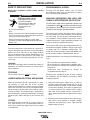
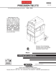
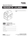
PRECISION TIG 275
For use with machines having Code Numbers:
September, 2007
11158; 11159
Safety Depends on You
Lincoln arc welding and cutting
equipment is designed and built
with safety in mind. However, your
overall safety can be increased by
proper installation ... and thoughtful
operation on your part. DO NOT
INSTALL, OPERATE OR REPAIR
THIS EQUIPMENT WITHOUT
READING THIS MANUAL AND
THE SAFETY PRECAUTIONS
CONTAINED
THROUGHOUT.
And, most importantly, think before
you act and be careful.
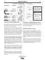
Precision TIG 275 Welding
Package shown with optional
Advanced Control Panel
IP21S
OPERATORʼS MANUAL
Copyright © 2007 Lincoln Global Inc.
• World's Leader in Welding and Cutting Products •
• Sales and Service through Subsidiaries and Distributors Worldwide •
Cleveland, Ohio 44117-1199 U.S.A. TEL: 216.481.8100 FAX: 216.486.1751 WEB SITE: www.lincolnelectric.com
i
i
SAFETY
WARNING
CALIFORNIA PROPOSITION 65 WARNINGS
For Gasoline Engines: The engine exhaust from
For Diesel Engines: Diesel engine exhaust and
this product contains chemicals known to the
some of its constituents are known to the State
State of California to cause cancer, birth defects,
of California to cause cancer, birth defects, and
or other reproductive harm.
other reproductive harm.
ARC WELDING CAN BE HAZARDOUS. PROTECT YOURSELF AND OTHERS FROM POSSIBLE SERIOUS INJURY OR DEATH.
KEEP CHILDREN AWAY. PACEMAKER WEARERS SHOULD CONSULT WITH THEIR DOCTOR BEFORE OPERATING.
Read and understand the following safety highlights. For additional safety information, it is strongly recommended that you
purchase a copy of “Safety in Welding & Cutting - ANSI Standard Z49.1” from the American Welding Society, P.O. Box 351040,
Miami, Florida 33135 or CSA Standard W117.2-1974. A Free copy of “Arc Welding Safety” booklet E205 is available from the
Lincoln Electric Company, 22801 St. Clair Avenue, Cleveland, Ohio 44117-1199.
BE SURE THAT ALL INSTALLATION, OPERATION, MAINTENANCE AND REPAIR PROCEDURES ARE
PERFORMED ONLY BY QUALIFIED INDIVIDUALS.
FOR ENGINE
powered equipment.
1.h. To avoid scalding, do not remove the
radiator pressure cap when the engine is
hot.
1.a. Turn the engine off before troubleshooting and maintenance
work unless the maintenance work requires it to be running.
____________________________________________________
1.b.Operate engines in open, well-ventilated
areas or vent the engine exhaust fumes
outdoors.
____________________________________________________
1.c. Do not add the fuel near an open flame welding arc or when the engine is running. Stop
the engine and allow it to cool before refueling to prevent spilled fuel from vaporizing on
contact with hot engine parts and igniting. Do
not spill fuel when filling tank. If fuel is spilled,
wipe it up and do not start engine until fumes
have been eliminated.
____________________________________________________
1.d. Keep all equipment safety guards, covers and devices in position and in good repair.Keep hands, hair, clothing and tools
away from V-belts, gears, fans and all other moving parts
when starting, operating or repairing equipment.
____________________________________________________
1.e. In some cases it may be necessary to remove safety
guards to perform required maintenance. Remove
guards only when necessary and replace them when the
maintenance requiring their removal is complete.
Always use the greatest care when working near moving
parts.
___________________________________________________
1.f. Do not put your hands near the engine fan.
Do not attempt to override the governor or
idler by pushing on the throttle control rods
while the engine is running.
ELECTRIC AND
MAGNETIC FIELDS
may be dangerous
2.a. Electric current flowing through any conductor causes
localized Electric and Magnetic Fields (EMF). Welding
current creates EMF fields around welding cables and
welding machines
2.b. EMF fields may interfere with some pacemakers, and
welders having a pacemaker should consult their physician
before welding.
2.c. Exposure to EMF fields in welding may have other health
effects which are now not known.
2.d. All welders should use the following procedures in order to
minimize exposure to EMF fields from the welding circuit:
2.d.1. Route the electrode and work cables together - Secure
them with tape when possible.
2.d.2. Never coil the electrode lead around your body.
2.d.3. Do not place your body between the electrode and
work cables. If the electrode cable is on your right
side, the work cable should also be on your right side.
2.d.4. Connect the work cable to the workpiece as close as
possible to the area being welded.
___________________________________________________
1.g. To prevent accidentally starting gasoline engines while
turning the engine or welding generator during maintenance
work, disconnect the spark plug wires, distributor cap or
magneto wire as appropriate.
2.d.5. Do not work next to welding power source.
Mar ʻ95
ii
ii
SAFETY
ELECTRIC SHOCK can kill.
ARC RAYS can burn.
3.a. The electrode and work (or ground) circuits
are electrically “hot” when the welder is on.
Do not touch these “hot” parts with your bare
skin or wet clothing. Wear dry, hole-free
gloves to insulate hands.
4.a. Use a shield with the proper filter and cover
plates to protect your eyes from sparks and
the rays of the arc when welding or observing
open arc welding. Headshield and filter lens
should conform to ANSI Z87. I standards.
3.b. Insulate yourself from work and ground using dry insulation.
Make certain the insulation is large enough to cover your full
area of physical contact with work and ground.
4.b. Use suitable clothing made from durable flame-resistant
material to protect your skin and that of your helpers from
the arc rays.
In addition to the normal safety precautions, if welding
must be performed under electrically hazardous
conditions (in damp locations or while wearing wet
clothing; on metal structures such as floors, gratings or
scaffolds; when in cramped positions such as sitting,
kneeling or lying, if there is a high risk of unavoidable or
accidental contact with the workpiece or ground) use
the following equipment:
• Semiautomatic DC Constant Voltage (Wire) Welder.
• DC Manual (Stick) Welder.
• AC Welder with Reduced Voltage Control.
4.c. Protect other nearby personnel with suitable, non-flammable
screening and/or warn them not to watch the arc nor expose
themselves to the arc rays or to hot spatter or metal.
3.c. In semiautomatic or automatic wire welding, the electrode,
electrode reel, welding head, nozzle or semiautomatic
welding gun are also electrically “hot”.
3.d. Always be sure the work cable makes a good electrical
connection with the metal being welded. The connection
should be as close as possible to the area being welded.
3.e. Ground the work or metal to be welded to a good electrical
(earth) ground.
3.f. Maintain the electrode holder, work clamp, welding cable and
welding machine in good, safe operating condition. Replace
damaged insulation.
3.g. Never dip the electrode in water for cooling.
3.h. Never simultaneously touch electrically “hot” parts of
electrode holders connected to two welders because voltage
between the two can be the total of the open circuit voltage
of both welders.
3.i. When working above floor level, use a safety belt to protect
yourself from a fall should you get a shock.
3.j. Also see Items 6.c. and 8.
FUMES AND GASES
can be dangerous.
5.a. Welding may produce fumes and gases
hazardous to health. Avoid breathing these
fumes and gases. When welding, keep
your head out of the fume. Use enough
ventilation and/or exhaust at the arc to keep
fumes and gases away from the breathing zone. When
welding with electrodes which require special
ventilation such as stainless or hard facing (see
instructions on container or MSDS) or on lead or
cadmium plated steel and other metals or coatings
which produce highly toxic fumes, keep exposure as
low as possible and below Threshold Limit Values (TLV)
using local exhaust or mechanical ventilation. In
confined spaces or in some circumstances, outdoors, a
respirator may be required. Additional precautions are
also required when welding on galvanized steel.
5. b. The operation of welding fume control equipment is affected
by various factors including proper use and positioning of the
equipment, maintenance of the equipment and the specific
welding procedure and application involved. Worker exposure level should be checked upon installation and periodically thereafter to be certain it is within applicable OSHA PEL
and ACGIH TLV limits.
5.c. Do not weld in locations near chlorinated hydrocarbon vapors
coming from degreasing, cleaning or spraying operations.
The heat and rays of the arc can react with solvent vapors to
form phosgene, a highly toxic gas, and other irritating products.
5.d. Shielding gases used for arc welding can displace air and
cause injury or death. Always use enough ventilation,
especially in confined areas, to insure breathing air is safe.
5.e. Read and understand the manufacturerʼs instructions for this
equipment and the consumables to be used, including the
material safety data sheet (MSDS) and follow your
employerʼs safety practices. MSDS forms are available from
your welding distributor or from the manufacturer.
5.f. Also see item 1.b.
AUG 06
iii
iii
SAFETY
WELDING SPARKS can
cause fire or explosion.
6.a. Remove fire hazards from the welding area.
If this is not possible, cover them to prevent
the welding sparks from starting a fire.
Remember that welding sparks and hot
materials from welding can easily go through small cracks
and openings to adjacent areas. Avoid welding near
hydraulic lines. Have a fire extinguisher readily available.
6.b. Where compressed gases are to be used at the job site,
special precautions should be used to prevent hazardous
situations. Refer to “Safety in Welding and Cutting” (ANSI
Standard Z49.1) and the operating information for the
equipment being used.
6.c. When not welding, make certain no part of the electrode
circuit is touching the work or ground. Accidental contact can
cause overheating and create a fire hazard.
6.d. Do not heat, cut or weld tanks, drums or containers until the
proper steps have been taken to insure that such procedures
will not cause flammable or toxic vapors from substances
inside. They can cause an explosion even though they have
been “cleaned”. For information, purchase “Recommended
Safe Practices for the Preparation for Welding and Cutting of
Containers and Piping That Have Held Hazardous
Substances”, AWS F4.1 from the American Welding Society
(see address above).
6.e. Vent hollow castings or containers before heating, cutting or
welding. They may explode.
6.f. Sparks and spatter are thrown from the welding arc. Wear oil
free protective garments such as leather gloves, heavy shirt,
cuffless trousers, high shoes and a cap over your hair. Wear
ear plugs when welding out of position or in confined places.
Always wear safety glasses with side shields when in a
welding area.
6.g. Connect the work cable to the work as close to the welding
area as practical. Work cables connected to the building
framework or other locations away from the welding area
increase the possibility of the welding current passing
through lifting chains, crane cables or other alternate circuits.
This can create fire hazards or overheat lifting chains or
cables until they fail.
6.h. Also see item 1.c.
6.I. Read and folllow NFPA 51B “ Standard for Fire Prevention
During Welding, Cutting and Other Hot Work”, available from
NFPA, 1 Batterymarch Park,PO box 9101, Quincy, Ma
022690-9101.
6.j. Do not use a welding power source for pipe thawing.
CYLINDER may explode
if damaged.
7.a. Use only compressed gas cylinders
containing the correct shielding gas for the
process used and properly operating
regulators designed for the gas and
pressure used. All hoses, fittings, etc. should be suitable for
the application and maintained in good condition.
7.b. Always keep cylinders in an upright position securely
chained to an undercarriage or fixed support.
7.c. Cylinders should be located:
• Away from areas where they may be struck or subjected to
physical damage.
• A safe distance from arc welding or cutting operations and
any other source of heat, sparks, or flame.
7.d. Never allow the electrode, electrode holder or any other
electrically “hot” parts to touch a cylinder.
7.e. Keep your head and face away from the cylinder valve outlet
when opening the cylinder valve.
7.f. Valve protection caps should always be in place and hand
tight except when the cylinder is in use or connected for
use.
7.g. Read and follow the instructions on compressed gas
cylinders, associated equipment, and CGA publication P-l,
“Precautions for Safe Handling of Compressed Gases in
Cylinders,” available from the Compressed Gas Association
1235 Jefferson Davis Highway, Arlington, VA 22202.
FOR ELECTRICALLY
powered equipment.
8.a. Turn off input power using the disconnect
switch at the fuse box before working on
the equipment.
8.b. Install equipment in accordance with the U.S. National
Electrical Code, all local codes and the manufacturerʼs
recommendations.
8.c. Ground the equipment in accordance with the U.S. National
Electrical Code and the manufacturerʼs recommendations.
Jan 07
iv
SAFETY
PRÉCAUTIONS DE SÛRETÉ
Pour votre propre protection lire et observer toutes les instructions
et les précautions de sûreté specifiques qui parraissent dans ce
manuel aussi bien que les précautions de sûreté générales suivantes:
Sûreté Pour Soudage A LʼArc
1. Protegez-vous contre la secousse électrique:
a. Les circuits à lʼélectrode et à la piéce sont sous tension
quand la machine à souder est en marche. Eviter toujours
tout contact entre les parties sous tension et la peau nue
ou les vétements mouillés. Porter des gants secs et sans
trous pour isoler les mains.
b. Faire trés attention de bien sʼisoler de la masse quand on
soude dans des endroits humides, ou sur un plancher metallique ou des grilles metalliques, principalement dans
les positions assis ou couché pour lesquelles une grande
partie du corps peut être en contact avec la masse.
c. Maintenir le porte-électrode, la pince de masse, le câble de
soudage et la machine à souder en bon et sûr état defonctionnement.
d.Ne jamais plonger le porte-électrode dans lʼeau pour le
refroidir.
e. Ne jamais toucher simultanément les parties sous tension
des porte-électrodes connectés à deux machines à souder
parce que la tension entre les deux pinces peut être le total
de la tension à vide des deux machines.
f. Si on utilise la machine à souder comme une source de
courant pour soudage semi-automatique, ces precautions
pour le porte-électrode sʼapplicuent aussi au pistolet de
soudage.
2. Dans le cas de travail au dessus du niveau du sol, se protéger
contre les chutes dans le cas ou on recoit un choc. Ne jamais
enrouler le câble-électrode autour de nʼimporte quelle partie du
corps.
3. Un coup dʼarc peut être plus sévère quʼun coup de soliel, donc:
a. Utiliser un bon masque avec un verre filtrant approprié ainsi
quʼun verre blanc afin de se protéger les yeux du rayonnement de lʼarc et des projections quand on soude ou
quand on regarde lʼarc.
b. Porter des vêtements convenables afin de protéger la peau
de soudeur et des aides contre le rayonnement de lʻarc.
c. Protéger lʼautre personnel travaillant à proximité au
soudage à lʼaide dʼécrans appropriés et non-inflammables.
4. Des gouttes de laitier en fusion sont émises de lʼarc de
soudage. Se protéger avec des vêtements de protection libres
de lʼhuile, tels que les gants en cuir, chemise épaisse, pantalons sans revers, et chaussures montantes.
5. Toujours porter des lunettes de sécurité dans la zone de
soudage. Utiliser des lunettes avec écrans lateraux dans les
zones où lʼon pique le laitier.
iv
6. Eloigner les matériaux inflammables ou les recouvrir afin de
prévenir tout risque dʼincendie dû aux étincelles.
7. Quand on ne soude pas, poser la pince à une endroit isolé de
la masse. Un court-circuit accidental peut provoquer un
échauffement et un risque dʼincendie.
8. Sʼassurer que la masse est connectée le plus prés possible de
la zone de travail quʼil est pratique de le faire. Si on place la
masse sur la charpente de la construction ou dʼautres endroits
éloignés de la zone de travail, on augmente le risque de voir
passer le courant de soudage par les chaines de levage,
câbles de grue, ou autres circuits. Cela peut provoquer des
risques dʼincendie ou dʼechauffement des chaines et des
câbles jusquʼà ce quʼils se rompent.
9. Assurer une ventilation suffisante dans la zone de soudage.
Ceci est particuliérement important pour le soudage de tôles
galvanisées plombées, ou cadmiées ou tout autre métal qui
produit des fumeés toxiques.
10. Ne pas souder en présence de vapeurs de chlore provenant
dʼopérations de dégraissage, nettoyage ou pistolage. La
chaleur ou les rayons de lʼarc peuvent réagir avec les vapeurs
du solvant pour produire du phosgéne (gas fortement toxique)
ou autres produits irritants.
11. Pour obtenir de plus amples renseignements sur la sûreté, voir
le code “Code for safety in welding and cutting” CSA Standard
W 117.2-1974.
PRÉCAUTIONS DE SÛRETÉ POUR
LES MACHINES À SOUDER À
TRANSFORMATEUR ET À
REDRESSEUR
1. Relier à la terre le chassis du poste conformement au code de
lʼélectricité et aux recommendations du fabricant. Le dispositif
de montage ou la piece à souder doit être branché à une
bonne mise à la terre.
2. Autant que possible, Iʼinstallation et lʼentretien du poste seront
effectués par un électricien qualifié.
3. Avant de faires des travaux à lʼinterieur de poste, la debrancher à lʼinterrupteur à la boite de fusibles.
4. Garder tous les couvercles et dispositifs de sûreté à leur place.
Mar. ʻ93
v
v
Thank You
for selecting a QUALITY product by Lincoln Electric. We want you
to take pride in operating this Lincoln Electric Company product •••
as much pride as we have in bringing this product to you!
CUSTOMER ASSISTANCE POLICY
The business of The Lincoln Electric Company is manufacturing and selling high quality welding equipment, consumables, and cutting equipment. Our challenge is to meet the needs of our customers and to exceed their expectations. On occasion, purchasers may ask Lincoln Electric
for advice or information about their use of our products. We respond to our customers based on the best information in our possession at that
time. Lincoln Electric is not in a position to warrant or guarantee such advice, and assumes no liability, with respect to such information or
advice. We expressly disclaim any warranty of any kind, including any warranty of fitness for any customerʼs particular purpose, with respect
to such information or advice. As a matter of practical consideration, we also cannot assume any responsibility for updating or correcting any
such information or advice once it has been given, nor does the provision of information or advice create, expand or alter any warranty with
respect to the sale of our products.
Lincoln Electric is a responsive manufacturer, but the selection and use of specific products sold by Lincoln Electric is solely within the control
of, and remains the sole responsibility of the customer. Many variables beyond the control of Lincoln Electric affect the results obtained in
applying these types of fabrication methods and service requirements.
Subject to Change – This information is accurate to the best of our knowledge at the time of printing. Please refer to www.lincolnelectric.com
for any updated information.
Please Examine Carton and Equipment For Damage Immediately
When this equipment is shipped, title passes to the purchaser upon receipt by the carrier. Consequently, Claims
for material damaged in shipment must be made by the purchaser against the transportation company at the time
the shipment is received.
Please record your equipment identification information below for future reference. This information can be found
on your machine nameplate.
Product _________________________________________________________________________________
Model Number ___________________________________________________________________________
Code Number or Date Code_________________________________________________________________
Serial Number____________________________________________________________________________
Date Purchased___________________________________________________________________________
Where Purchased_________________________________________________________________________
Whenever you request replacement parts or information on this equipment, always supply the information you
have recorded above. The code number is especially important when identifying the correct replacement parts.
On-Line Product Registration
- Register your machine with Lincoln Electric either via fax or over the Internet.
• For faxing: Complete the form on the back of the warranty statement included in the literature packet
accompanying this machine and fax the form per the instructions printed on it.
• For On-Line Registration: Go to our WEB SITE at www.lincolnelectric.com. Choose “Quick Links” and then
“Product Registration”. Please complete the form and submit your registration.
Read this Operators Manual completely before attempting to use this equipment. Save this manual and keep it
handy for quick reference. Pay particular attention to the safety instructions we have provided for your protection.
The level of seriousness to be applied to each is explained below:
WARNING
This statement appears where the information must be followed exactly to avoid serious personal injury or loss of life.
CAUTION
This statement appears where the information must be followed to avoid minor personal injury or damage to this equipment.
vi
vi
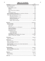
TABLE OF CONTENTS
Page.
Installation ..........................................................................................................Section A
Technical Specifications........................................................................................A-1, A-2
Safety Precautions.. ............................................................................................................................................... .A-3
Select Suitable Location ........................................................................................A-3
Grinding .................................................................................................................A-3
Stacking .................................................................................................................A-3
Undercarriage Lifting and Moving .........................................................................A-3
Tilting .....................................................................................................................A-3
Environmental Rating ............................................................................................A-3
Machine Grounding and High Frequency Interference Protection .......................A-3, A-4
Input and Grounding Connections ..............................................................................A-4
Output Cable, Connections and Limitations ................................................................A-5
Work Cable Connection ..................................................................................A-5
Stick Electrode Cable Connection ..................................................................A-5
TIG Torch Connection .....................................................................................A-6
Auxiliary Power Connections ..........................................................................A-7
Remote Control (If Used) ................................................................................A-7
Robotic Interface Connection ..................................................................A-7, A-8
________________________________________________________________________
OPERATION..........................................................................................................................................................Section B-1
Safety Precautions .......................................................................................................B-1
Product Description......................................................................................................B-1
Pipe Thawing .........................................................................................................B-1
Duty Cycle: ............................................................................................................B-1
Recommended Processes and Equipment ...........................................................B-2
Controls and Settings .............................................................................B-3 Thru B-6
Internal Set Up Controls ........................................................................................B-7
Stick Welding Features..........................................................................................B-7
TIG Welding Features ...........................................................................................B-7
2 Step Trigger Modes......................................................................................B-8
4 Step Trigger Modes ....................................................................................B-9
TIG Welding Cycle Chart ....................................................................................B-10
Setup Guidelines for TIG Welding with an Amptrol .....................................B-10, B11
Making a TIG Weld with an Amptrol....................................................................B-12
________________________________________________________________________
Accessories ............................................................................................................................................... .......Section C
Optional Equipment .....................................................................................................C-1
________________________________________________________________________
Maintenance ......................................................................................................................................................Section D
Safety Precautions.......................................................................................................D-1
Routine and Periodic Maintenance..............................................................................D-1
Overload Protection .....................................................................................................D-1
Service Procedures, Component Access,Spark Gap Adjustment ...............................D-2
Under-Cooler Service ..................................................................................................D-2
Meter Calibration Adjustment.......................................................................................D-3
________________________________________________________________________
Troubleshooting .............................................................................................................................................Section E
Safety Precautions .......................................................................................................E-1
How To Use TroubleShooting Guide............................................................................E-1
Troubleshooting .................................................................................................E-2 to E-7
________________________________________________________________________
Diagrams ..............................................................................................................................................................Section F
Wiring Diagrams ..............................................................................................................................................F-1, F-2
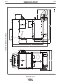
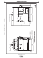
Dimension Prints .............................................................................................................................................F-3, F-4
________________________________________________________________________
Parts List ......................................................................................................................................................................P-558
A-1
A-1
INSTALLATION
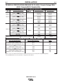
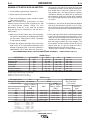
TECHNICAL SPECIFICATIONS-PRECISION TIG 275 (K2618-1 Domestic Package*-60Hz)
(K2619-1 Domestic,K2619-2 Canadian-60Hz)
RATED INPUT - SINGLE PHASE ONLY
K
Number
Duty Cycle-Applications
40%
AC/DC Stick / Balance TIG
K2618-1 Unbalance (70% Penetration#) AC TIG
60%
AC/DC Stick / Balance TIG
K2619-1
Unbalance (70% Penetration#) AC TIG
100%
AC/DC Stick / Balance TIG
Unbalance (70% Penetration#) AC TIG
Idle Amps
40%
AC/DC Stick / Balance TIG
Unbalance (70% Penetration#) AC TIG
60%
AC/DC Stick / Balance TIG
K2619-2 Unbalance (70% Penetration#) AC TIG
100%
AC/DC Stick / Balance TIG
Unbalance (70% Penetration#) AC TIG
Idle Amps
Idle Power
Voltage + 10%
Max. Amps With Out
Max. Amps With
Power Factor Capacitor Power Factor Capacitor
208/230/460
104/94/47
124/112/56
80/72/36
95/86/43
86/78/39
95/86/43
64/58/29
62/56/28
77/70/35
73/66/33
6/5/3
55/50/25
40/36/18
36/32/16
47/38
56/45
35/28
43/34
39/31
43/35
29/23
28/23
35/28
33/26
3/2
300W
25/20
18/14
16/13
500W
460/575
RATED POWER FACTOR (STICK) K2618-1,K2619-1 & K2619-2
.63 min.
.85 min.
RATED OUTPUT - NEMA EW1 Class ll (40)
Duty Cycle-Applications
40%
AC/DC Stick / Balance TIG
Unbalance (70% Penetration#) AC TIG
60%
AC/DC Stick / Balance TIG
Unbalance (70% Penetration#) AC TIG
100%
AC/DC Stick / Balance TIG
Unbalance (70% Penetration#) AC TIG
Volts at Rated Amperes
Amps
31.0
16.1
275
255
29.0
15.4
225
200
28.0
14.8
200
150
*Shown on Front of this IM manual with Under-Cooler Cart and Advanced Control Panel (Refer to Optional Equipment)
#Exceeds
NEMA Unbalanced Load Specification comparable for Auto-Balance.
PRECISION TIG 275
A-2
A-2
INSTALLATION
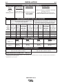
ADDITIONAL OUTPUT CAPACITY
Output Current
Range
Type of Output
Maximum Open
Circuit Voltage
Auxiliary Power
15Amp Circuit Breaker and NEMA 5-15R Duplex
Receptacle for up to:
115VAC 8Amp Auxiliary Power Receptacle
115VAC weld Switched Cooler Receptacle load
2Amps DC
(STICK AND TIG)
to
CC (Constant Current)
AC/DC
OCV: 75/68
340Amps AC-DC*
AC/DC (GTAW)
Stick (SMAW)
RECOMMENDED INPUT WIRE AND FUSE SIZES
For all Stick, DC TIG, and Balanced AC TIG Welding
at 275A/40% Duty Cycle with out Standard Power
Factor Correction Capacitors
Based on the 1999 U.S. National Electrical Code
For Unbalanced AC TIG Welding Above 275 Amps:
255A/40% Duty Cycle, Auto-Balance Penetration with
out Standard Power Factor Correction Capacitors
Based on the 1999 U.S. National Electrical Code
Input
Type 75°C
Type 75°C
Input
Ampere Copper Wire in
Fuse
Fuse
Copper
Conduit AWG
Voltage / (Super Lag) Rating
Ground Wire in (Super Lag)
(IEC) Sizes
phase/
or Breaker Rating on
Conduit AWG or Breaker
40°C (104°F)
Frequency
Nameplate
Size1
Size1
(IEC) Sizes
Ambient
Input
Ampere
Rating
Type 75°C
Copper Wire in
Conduit AWG
(IEC) Sizes
40°C (104°F)
Ambient
Type 75°C
Copper
Ground Wire in
Conduit AWG
(IEC) Sizes
208/1/60
125
104
4 (21.2 mm2)
6 (13.3 mm2)
150
124
3 (26.7 mm2)
6 (13.3 mm2)
230/1/60
125
94
4 (21.2 mm2)
6 (13.3 mm2)
150
112
3 (26.7 mm2)
6 (13.3 mm2)
460/1/60
60
47
8 (8.4mm2)
10 (5.3mm2)
70
56
8 (8.4 mm2)
8 (8.4 mm2)
575/1/60
50
38
10 (5.3mm2)
10 (5.3mm2)
60
45
8 (8.4 mm2)
10 (5.3mm2)
PHYSICAL DIMENSIONS
K2619-1, -2
Height
31.0 in.
787 mm
Width
22.0 in.
559 mm
Depth
26.0 in.
660 mm
Weight
Approx. 397 lbs.
180 kgs.
K2618-1
49.7 in.
1262 mm
28.0 in.
711 mm
41.0 in.
1041 mm
Approx.641 lbs.
291 kgs.
TEMPERATURE RANGES
OPERATING TEMPERATURE RANGE
-20°C to +40°C (-04° to +104°F)
TRANSFORMER INSULATION CLASS
STORAGE TEMPERATURE RANGE
-40°C to +85°C (-40° to +185°F)
180°C (H)
1 ALSO CALLED ʻINVERSE TIME" OR "THERMAL/MAGNETIC " CIRCUIT BREAKERS; CIRCUIT BREAKERS WHICH HAVE A DELAY IN TRIPPING ACTION THAT DECREASES AS
THE MAGNITUDE OF CURRENT INCREASES.
* 50/60H
Z
IEC Max. range exceeds 310A.
PRECISION TIG 275
A-3
INSTALLATION
A-3
SAFETY PRECAUTIONS
ENVIRONMENTAL RATING
Read entire installation section before starting
installation.
Precision TIG 275 power sources carry an IP21S
Environmental rating. They are rated for use in damp,
dirty rain-sheltered environments.
WARNING
MACHINE GROUNDING AND HIGH FREQUENCY INTERFERENCE PROTECTION
ELECTRIC SHOCK can kill.
• Only qualified personnel should
perform this installation.
• Turn the input power OFF at the
disconnect switch or fuse box
before working on this
equipment.
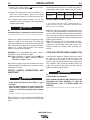
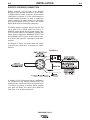
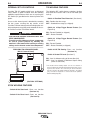
The frame of the welder must be grounded. A ground screw
marked with the symbol is located on the input connection
panel (Figure A.1) for this purpose. See your local and national electrical codes for proper grounding methods.
• Do not touch electrically hot
parts.
• Always connect the Precision TIG 275 grounding screw (behind
the reconnect panel cover located near the back of the left case
side) to a good electrical earth ground.
• Always connect the Precision TIG 275 to a power supply
grounded in accordance with the National Electrical Code and
all local codes.
SELECT SUITABLE LOCATION
Place the welder where clean cooling air can freely circulate in through the top rear vents and out through the
bottom rear vents. Dirt, dust or any foreign material
that can be drawn into the welder should be kept at a
minimum. Failure to observe these precautions can
result in excessive operating temperatures and nuisance trips.
GRINDING
Do not direct grinding particles towards the welder. An
abundance of conductive material can cause maintenance problems.
STACKING
The Precision TIG 275's cannot be stacked .
UNDERCARRIAGE LIFTING AND MOVING
When the Precision TIG 275 is purchased as a welding package, or used with any of the available
Undercarriage optional accessories, proper installation
makes the Precision TIG 275 lift bale nonfunctional.
Do not attempt to lift the power source with an undercarriage attached. The undercarriage is designed for
hand moving only; mechanized movement can lead to
personal injury and/or damage to the Precision TIG
275.
TILTING
Each machine must be placed on a secure, level surface, either directly or on a recommended undercarriage. The machine may topple over if this precaution
is not followed.
The spark gap oscillator in the high frequency generator, being similar to a radio transmitter, can be blamed
for many radio, TV and electronic equipment interference problems. These problems may be the result of
radiated interference. Proper grounding methods can
reduce or eliminate radiated interference.
The Precision TIG 275 has been field tested under recommended installation conditions and has been found
to comply with F.C.C. allowable radiation limits. This
welder has also been found to comply with NEMA standards for high frequency stabilized power sources.
Radiated interference can develop in the following four
ways:
• Direct interference radiated from the welder.
• Direct interference radiated from the welding leads.
• Direct interference radiated from feedback into the
power lines.
• Interference from re-radiation of "pickup" by
ungrounded metallic objects.
Keeping these contributing factors in mind, installing
the equipment per the following instructions should
minimize problems:
1. Keep the welder power supply lines as short as
possible. Input leads within 50 feet (15.2 m) of the
welder should be enclosed in rigid metallic conduit
or equivalent shielding. There must be good electrical contact between this conduit and the welder.
Both ends of the conduit must be connected to a
driven ground and the entire length must be continuous.
2. Keep the work and electrode leads as short as possible and as close together as possible. Lengths
should not exceed 25 feet (7.6 m). Tape the leads
together when practical.
PRECISION TIG 275
A-4
A-4
INSTALLATION
3. Be sure the torch and work cable rubber coverings
are free of cuts and cracks that allow high frequency leakage. Cables with high natural rubber content,
such as Lincoln Stable-Arc®, better resist high frequency leakage than neoprene and other synthetic
rubber insulated cables.
INPUT and GROUNDING CONNECTIONS
WARNING
ELECTRIC SHOCK can kill.
• Turn the input power OFF at the
disconnect switch or fuse box
before working on this
equipment.
4. Keep the torch in good repair and all connections
tight to reduce high frequency leakage.
5. The work terminal must be connected to a ground
within ten feet of the welder, using one of the following methods:
Be sure the voltage, phase, and frequency of the input
power is as specified on the rating plate, located on the
rear of the machine.
• A metal underground water pipe in direct contact
with the earth for ten feet or more.
Fuse the input circuit with the recommended super lag
fuses or delay type1 circuit breakers. Choose an input
and grounding wire size according to local or national
codes or use Section A-2. Using fuses or circuit breakers smaller than recommended may result in "nuisance" tripping from welder inrush currents even if not
welding at high currents.
• A 3/4" (19 mm) galvanized pipe or a 5/8" (16 mm)
solid galvanized iron, steel or copper rod driven at
least eight feet into the ground.
The ground should be securely made and the grounding cable should be as short as possible using cable of
the same size as the work cable, or larger. Grounding
to the building frame electrical conduit or a long pipe
system can result in re-radiation, effectively making
these members radiating antennas. (This is not recommended).
6. Keep all access panels and covers securely in
place.
7. All electrical conductors within 50 feet (15.2 m) of
the welder should be enclosed in grounded rigid
metallic conduit or equivalent shielding. Flexible
helically-wrapped metallic conduit is generally not
suitable.
8. When the welder is enclosed in a metal building,
several good earth driven electrical grounds (as in 5
above) around the periphery of the building are recommended.
Failure to observe these recommended installation
procedures can cause radio or TV interference problems and result in unsatisfactory welding performance
resulting from lost high frequency power.
Unbalanced AC TIG welding draws higher input currents than those for Stick, DC TIG, or Balanced AC TIG
welding. The welder is designed for these higher input
currents. However, where unbalanced AC TIG welding
above 185 amps is planned, the higher input currents
require larger input wire sizes and fuses per Section A-2:
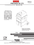
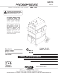
Remove the reconnect panel cover located near the
back of the left case side to reveal the reconnect panel.
Welder supply line entry provision is in the case rear
panel. Entry is through a 1.75 inch (44 mm) diameter
hole in the case back. Appropriate supply line strain
relief clamp is provided by installer. (See Figure A.1)
FIGURE A.1
CONNECT INPUT
POWER LEADS
CONNECT INPUT
GROUND LEAD
CONNECT INPUT
VOLTAGE LEVEL
All connections should be made in accordance
with all local codes and national electrical codes.
Installation by a qualified electrician is recommended.
PRECISION TIG 275
A-5
A-5
INSTALLATION
1. Connect the terminal marked
nect panel) to an earth ground.
(below the recon-
Recommended Cable Sizes for Combined Lengths of
Copper Work and Electrode Cables using 75o C Wire:
2. Connect the input leads to terminals marked L1 (U)
and L2 (V) on the reconnect panel. Use a single
phase line or one phase of a two or three phase line.
Machine Rating
3. On multiple input voltage welders, be sure the
reconnect panel is connected for the voltage being
supplied to the welder.
WORK CABLE CONNECTION
CAUTION
Failure to follow these instructions can cause
immediate failure of components within the welder.
------------------------------------------------------------------------
Welders are shipped connected for the highest input
voltage as listed on the rating plate. To change this
connection, designations on the reconnect panel LOW,
MID, and HIGH correspond to the name plated input
voltages of a triple voltage welder. Dual voltage
welders use only LOW and HIGH.
EXAMPLE: On a 208/230/460 volt welder, LOW is
208V, MID is 230V, and HIGH is 460V.
Note: Export model has a voltage range for LOW and
MID connections: LOW is 220-230V, MID is
380-400V and High is 415V.
Reconnect the jumper strap to the terminal stud corresponding to the input voltage level used. Make sure all
connections are tight.
275A/40%
0 to 100 Ft.
101 to 200 Ft
201 to 250 Ft
#1 (42.4 mm2) 1/0 (53.5 mm2) 2/0 (67.4 mm2)
A 15ʼ (2/0) weld cable with clamp is available (K2150-1), or
included with the Precision TIG Welding Package model.
Otherwise, it is user provided.
With power source off, connect a separate work cable
to the 1/2-13 threaded "WORK" stud of the welder, and
secure a tight connection with the flange nut provided.
The work cable should be routed through the cable
strain relief hole provided in the base directly below the
welding output terminal.
Note: If the Precision TIG is equipped with an UnderCooler or Under-Storage unit, the coiled work cable
and clamp, or excess work cable length, may be conveniently stored in the drawer while remaining connected.
STICK ELECTRODE CABLE CONNECTION
If manual stick welding is desired, with power source
off, connect a stick electrode cable to the 1/2-13
threaded "STICK Electrode" stud of the welder, and
secure a tight connection with the flange nut provided.
The electrode cable should be routed through the
cable strain relief hole provided in the base directly
below the welding output terminal.
OUTPUT CABLES, CONNECTIONS AND
LIMITATIONS
WARNING
DISCONNECT STICK ELECTRODE
CABLE WHEN TIG WELDING.
WELDING
WARNING
• To avoid being startled by a high frequency
shock, keep the TIG torch and cables in good
condition
• Turn the power switch of the power source OFF
before installing adapters on cable or when connecting or disconnecting adapter plugs to power
source.
-----------------------------------------------------------------------
EVEN THOUGH HI-FREQ IS NOT APPLIED TO THE
PRECISION TIG STICK TERMINAL, IT WILL BE
ELECTRICALLY "HOT" TO WORK WHEN TIG
WELDING.
------------------------------------------------------------------------
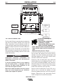
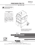
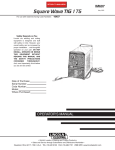
Refer to Figure A.2 for the location of the WORK and
STICK terminals, as well as the TIG Torch connection
panel.
PRECISION TIG 275
A-6
A-6
INSTALLATION
FIGURE A.2
TIG TO RCH
CONNECTIO N
PAN EL
REM OTE
CONTROL
RECEPTAC LE
STICK
WORK
WORK
STICK
ELE CTRODE
STUD
STUD
(Shown without hinged stud cover)
FIGURE A
TIG TORCH CONNECTION
The Precision TIG torch connection box, located on the
right side of the machine, provides all the input and
output connections for the installation of both aircooled and water-cooled TIG torches with fittings conforming to Compressed Gas Association (CGA) standards:
Note: The Precision TIG provides an insulated Torch
Reel and Holster for handy and safe storage of connected torch when not welding, and excess torch cable
length while welding.
WARNING
Combination connectors (Power/Water and
Power/Gas) are electrically "hot" while welding in
STICK or TIG modes.
CA BLE
STRAIN
REL I EF HOLE S
CYLINDER could explode
if damaged.
• Keep cylinder upright and
chained to a support.
• Keep cylinder away from areas
where it could be damaged.
• Never allow the torch to touch the cylinder.
• Keep cylinder away from live electrical circuits.
• Maximum inlet pressure 150 psi.
----------------------------------------------------------------The Precision TIG machines do not have Hi-Freq.
available at the Stick electrode stud, therefore stud
connection adapters (such as LECO. S19257-series)
cannot be used for torch connection.
If using an Air-Cooled Torch be sure coolant is
shut off and/or Cooler is unplugged from the
Precision TIG Water Cooler Receptacle on the
torch side of the upper case back.
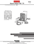
Single-piece cable air-cooled torches with a 3/8-24 RH
connector fitting (such as the Magnum PTA-9/-17, or LA9/-17) require the provided S20403-4 Torch Connector,
while those with a 7/8-14 RH connector fitting (such as
the Magnum PTA-26, or LA-26) require the available
K2166-1 Torch Connector. (See Figure A.3)
Observe the safety precautions necessary for handling and using compressed gas containers.
Contact your supplier for specifics.
Two-piece cable air-cooled torches (such as PTA-, or LAtorches) can be used with the available 1/2” Stud
Connector (S20403-3) with with a 7/8-14 LH male fitting.
Magnum PTW-18/-20 (or LW-) water-cooled Torches
require no adapter for Precision TIG connection.
PRECISION TIG 275
A-7
A-7
INSTALLATION
FIGURE A.3
For Gas Supply hose
with 5/8-18RH male
(Provided with Weld
Package model)
For Coolant Supply
Hoses
with 5/8-18LH male
(Provided with Weld
Package model
or
Under-Cooler Cart)
AUXILIARY POWER CONNECTIONS
The Precision TIG machines provide a standard NEMA
5-15R duplex receptacle, located on the upper case
back on the torch side of the machine:
• The bottom outlet of this duplex receptacle provides
switched 115VAC power for the Under-Cooler, or
Water Solenoid accessory. This Cooler receptacle
turns on when the arc starts and remains on for about
8 minutes after the arc goes out (with the Fan-AsNeeded machine cooling fan, see Maintenance
Section), so the Coolerʼs fan and water pump will not
run continuously in idle, but will run while welding.
• The top outlet of this duplex receptacle provides at
least 8 amps at 115VAC, whenever the Precision TIG
Power switch is ON. This auxiliary circuit is intended
for running 115VAC accessories or small power tools.
Note: Some types of equipment, especially pumps
and large motors, have starting currents which are
significantly higher than their running current. These
higher starting currents may cause the circuit breaker
to open. (See next paragraph)
The Precision TIG Export models also provide a
grounded 220vac Euro type Schuko receptacle and a
5 amp circuit breaker, located on the upper case back
on the reconnect side of the machine, intended for use
with a 220vac water cooler.
REMOTE CONTROL (If Used)
The Foot Amptrol (included with the Precision TIG
Welding Package), or other Remote accessory, is
installed by routing the plug of its control cable up
through the left cable strain relief hole provided in the
base (see Figure A.2), then connecting the 6-pin plug
to the mating Remote receptacle behind the stud panel
cover. (See Operation Section B-2 for mating plug
wiring.)
Note: If the Precision TIG is equipped with an UnderCooler or Under-Storage unit, the Foot Pedal (or other
remote control accessory) and coiled control cable, or
excess cable length, may be conveniently stored in the
drawer while remaining connected.
• Both the receptacle circuits are protected from shorts
and overloads by a 15 amp circuit breaker, located
above the receptacle. If the breaker trips, its button
pops out exposing a red ring. When the circuit breaker cools, the button can be reset by pressing it back
in.
Note: When the breaker trips, not only will the auxiliary and cooler power be interrupted, but so will the
power to the shielding gas solenoid and machine
cooling fan.
PRECISION TIG 275
A-8
INSTALLATION
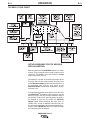
ROBOTIC INTERFACE CONNECTION
Robotic interface can be made at the Remote
Receptacle (See Operation Section B-2). The machine
is shipped with the remote receptacle circuit internally
connected to receptacle J5 of the Control board for
standard Amptrol operation. In order to enable the
remote receptacle for robotic interface its connection
plug must be moved from J5 to J5A on the Control
board. (Refer to the machine Wiring Diagram.)
The robotic interface functions with the Precision TIG
set to either TIG or STICK mode, but must be in
REMOTE switch position for the Preset Control interface to function. When in the REMOTE position with
robotic interface neither the MAXIMUM OUTPUT nor
the MINIMUM OUTPUT panel controls limit the interface control setting over the rated output range of the
machine.
The diagram in Figure A.4 below shows the remote
receptacle plug connections and signals for robotic
interface:
FIGURE A.4
In addition; a Peak Pulse output signal is provided at
J21 receptacle on the Advanced Control PCB. This
output provides a 0.2A rated switch circuit between pin
1 (+) and pin 2 (com) for an external 40VDC supplied
relay (with coil diode). This switch closes when the
Peak Pulse is on, and opens when off.
PRECISION TIG 275
A-8
OPERATION
B-1
B-1
SAFETY PRECAUTIONS
PRODUCT DESCRIPTION
Read and understand this entire section before operating the machine.
The Precision TIG 275 is part of a new family of industrial arc welding power sources providing constant current, single range square wave AC/DC TIG (GTAW)
with patented Micro-StartTM Technology, Presettable
Min. and Max. Output controls, and built-in high frequency stabilization for continuous AC TIG and DC TIG
starting. It also has AC/DC Stick (SMAW) capability,
with adjustable Arc Force availability. A TIG Pulse
Panel, Power Factor Capacitors and a Water Solenoid
are available as field installed optional kits. Also, a new
Undercarriage (with double gas bottle rack) is available
for field installation, as well as a new Under-Cooler
Cart, which is also included in an available efficiently
integrated entire TIG Welding Package with convenient built-in storage provisions for welding equipment
and components.
WARNING
ELECTRIC SHOCK can kill.
• Only qualified personnel should
perform this installation.
• Turn the input power OFF at the
disconnect switch or fuse box.
• Do not touch electrically live parts
or electrode with skin or wet clothing.
• Insulate yourself from work and
ground.
• Always wear dry insulating gloves.
• Read and follow “Electric Shock
Warnings” in the Safety section if welding must be performed under electrically hazardous conditions such as welding in wet areas or on or in the workpiece.
FUMES AND GASES
can be dangerous.
• Keep your head out of fumes.
• Use ventilation or exhaust to
remove fumes from breathing
zone.
WELDING SPARKS
can cause fire or
explosion
• Keep flammable material away.
• Do not weld on containers that
have held combustibles.
ARC RAYS
can burn.
The Precision TIG 275 includes advanced features
such as: Digital Meter, Presettable control, Auto
BalanceTM, Fan As Needed (F.A.N.) fixed Preflow, variable Postflow shielding gas and Timers. In addition, 2Step/4-Step and Pulse TIG operation with adjustable
Downslope Time control are included with an available
field installed kit. It also features a Stick stud panel and
a universal TIG torch connection box for simultaneous,
but separated, electrode outputs.
The Precision TIG 275 has enhanced Features which
includes the following:
• MicroStart™ II
• Auto-Balance optimized
• Menu button added
• Spot On selection added
PIPE THAWING
The Precision TIG 275 is not recommended for pipe
thawing.
• Wear eye, ear and body
protection.
Duty Cycle
Observe additional Safety Guidelines detailed in
the beginning of this manual.
The duty cycle is based upon a 10-minute time period;
i.e., for 40% duty cycle, it is 4 minutes welding and 6
minutes idling. If the rated duty cycle is significantly
exceeded, the thermostatic protection will shut off the
output until the machine cools to a normal operating
temperature. (Refer to Specification Section A-1)
PRECISION TIG 275
B-2
OPERATION
RECOMMENDED PROCESSES AND
EQUIPMENT
RECOMMENDED PROCESSES
The Precision TIG 275 is recommended for the TIG
(GTAW) and Stick (SMAW) welding processes within
its output capacity range of 2 amps DC, or 5 amps AC,
to 340 amps AC/DC. It is compatible with most
Magnum TIG accessories (refer Equipment
Limitations), as well as many industry standard items,
such as TIG torches, hoses, and water coolers.
B-2
EQUIPMENT LIMITATIONS
The Precision TIG machines are protected from overloads beyond the electrical ratings and duty cycles, per
the Specifications Section A-1, A-2, with Thermostat
protection of the primary and secondary transformer
coils.
The Precision TIG machines do not have Hi-Frequency
available at the Stick electrode stud, therefore stud
connection adapters (such as LECO. S19257-series)
cannot be used for torch connection.
PROCESS LIMITATIONS
Precision TIG machines are not recommended for arc
gouging due to it's limited output capacity, and are also
not recommended for pipe thawing.
RECOMMENDED EQUIPMENT/INTERFACE
Machine:
Input Cable/Clamp:
Gas Reg./Hose:
Magnum Torch:
Magnum Parts:
Work Clamp/Lead:
Foot Amptrol:
TIG (water cooled)
PT275 Welding Package (K2618-1)
User provided
(included)
(PTW20 included)
(KP510 and K918-2 included)
(15 ft. included)
(K870 included)
PRECISION TIG 275
TIG (air cooled)
PT275(K2619-1, -2)
User provided
LE/Harris 3100211
PTA9 or PTA17
KP507 or KP508
K2150-1 Work Lead Assembly
K870
B-3
B-3
OPERATION
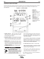
CONTROLS AND SETTINGS
The Front Control Panel contains the knobs and switches necessary for adjusting the operation of the Precision
TIG 275, with function indicator lights and an electronic display for volts and amps. The components are
described below:
FIGURE B.1 - CONTROL PANEL
7
8
7a
9
5
6
9
3
10
4
12
13
14
15
16
17
1
1. POWER SWITCH
2. POLARITY SWITCH
3. MODE SWITCH
4. AC BALANCE CONTROL
5. LOCAL/REMOTE CURRENT CONTROL
SWITCH
6. MAXIMUM OUTPUT CONTROL
7. MINIMUM OUTPUT CONTROL AND
DISPLAY SWITCH
7a. MENU BUTTON AND DISPLAY
SWITCH
8. DIGITAL METER AND DISPLAY
SWITCH
9. POSTFLOW TIME
10. THERMAL SHUTDOWN LIGHT
11. REMOTE RECEPTACLE
12. TRIGGER SWITCH
13. PULSE / SPOT MODE SWITCH
14. PULSE FREQUENCY CONTROL
15. PULSE % ON TIME CONTROL
16. PULSE BACKGROUND CURRENT
CONTROL
17. DOWNSLOPE TIME
11
2
1. POWER SWITCH - Input line switch turns input
power ON or OFF, as indicated by the on or off status of the front panel displays.
2. POLARITY SWITCH – The 3-position rotary power
switch has detente positions for DC-, AC and DC+
selections for the Electrode output welding polarity.
3. MODE SWITCH – The mode switch allows vertically positioned selection of the two machine welding
modes. The selected mode is indicated by a lit colored panel light which permits viewing the machine
setting from a distance:
3.a STICK mode (Top position) –Red panel light
WARNING
ELECTRIC SHOCK can kill.
• When the Power Source is ON in
STICK mode the Electrode circuits of
both the Stick and TIG torch cables
are electrically HOT to Work.
------------------------------------------------------------------------
• The CC Stick mode may be used for general purpose stick welding (SMAW ) within the capacity of
the machine. The capacity is too limited for arc air
carbon (AAC) gouging.
• In this mode; the output terminals are activated
electrically HOT, gas flow is not activated and HOT
START and ARC FORCE levels are fixed, or
Advanced Panel selectable (See Internal Set Up
controls), with no front panel adjustment.
3.b TIG mode (Bottom position) – No panel light.
• When the Polarity Switch is set to AC, the TIG
mode provides continuous high frequency to stabilize the arc for AC TIG welding.
Hi-Freq. turns on after preflow time with the arc
start switch closure, and turns off when the arc
goes out* after the arc start switch opens.
* Arc voltage and current are sensed to determine if
the arc is established or out.
PRECISION TIG 275
B-4
OPERATION
• When the Polarity Switch is set to DC (- or +), the
TIG mode provides high frequency only for starting.
Hi-Freq. turns on after pre-flow time with the arc
start switch closure, and turns off when the arc is
established.*
• Also functions for DC+ polarity to permit "balling" of
tungsten for AC TIG welding.
4. AC BALANCE CONTROL – The potentiometer
control permits AC wave balance adjustment from
Max. Penetration (~85% negative wave) with the
control at Max. full CW position, to Max. Cleaning
(~65% positive wave) with the control set near minimum CCW position.
• Full minimum CCW position is the Auto Balance
position which is indicated by the Green panel light
turning on. This feature automatically provides the
proper amount of cleaning and penetration for normal AC TIG welding
• The mid position is the Balanced position (~50%
positive and negative waves).
• The Balance control is only functional if the machine
is set to AC polarity and TIG mode.
5. LOCAL/REMOTE CURRENT CONTROL SWITCH – A
2-position switch selects how the welding output is
controlled for both Stick and TIG Modes:
• LOCAL (Top position) selects output control only by
the machine panel Output Control. (See Item 6)
• REMOTE (Bottom position) selects output control to
also be by an Amptrol (See Item 6), or other remote
(10K pot) control connected to the Remote receptacle (See Item 11). This switch selection is indicted
by the Green panel light turning on.
In either position the arc start switch functions when
connected to the Remote receptacle (See Item 11).
6. MAXIMUM OUTPUT CONTROL – The large knob
is used to set the output welding current over the
rated output range of the machine.
• With the Current Control switch to LOCAL position,
this knob sets the welding output level.
B-4
• With the Current Control switch to REMOTE position, this knob sets the maximum welding level that
the Peak output can be set with the remote Amptrol.
• The new MicroStartTM Technology minimum current
circuit provides for low end welding (down to 2
amps) previously unobtainable on an SCR platform
TIG machine.
7. MINIMUM OUTPUT CONTROL AND DISPLAY SWITCH–
A smaller knob is used to preset the minimum current level only for TIG mode. Pressing the Display
(momentary) switch toggle left to Minimum Set position displays the Minimum control level setting on the
Digital meter. (See Item 8)
• This knob sets the Start output level. When the arc
lights (using a new built-in TIG start pulse) this level
upslopes quickly (0.5 sec.w/ Advanced Panel, zero
w/o-See UP Menu of Item 7a) and smoothly to the
weld output level. The setting range for this Start
control is the 2 amp minimum range of the machine
up to about 50 amps, but no more than the level set
by the Maximum Output control knob (See Item 6),
but otherwise is independent of the Maximum setting.
• This setting also serves as the Crater-fill level, but
with a Precision TIG Advanced Panel it can be
selected (see Section B-7) to be either the Minimum
Output control setting (same as Start setting) as
shipped, or the minimum rating of the machine (2
amps).
• The Remote Amptrol range of control is between
this Minimum setting and the Maximum Output control knob setting, so these knobs can set the resolution of the Amptrol. Also, the Minimum setting
serves as both the minimum Amptrol start level
when the arc start switch is closed, as well as the
minimum Amptrol crater-fill level before the arc start
switch is opened to help prevent premature arc out
and Hi-Freq re-initiation.
• In STICK mode the Start control is not functional
since Hot Start level is fixed, or internal Advanced
Panel adjustable (see Section B-7). Pressing the
Display (momentary) switch toggle left to Minimum
Output position displays minimum amps rating of
the machine.
* Arc voltage and current are sensed to determine if
the arc is established or out.
PRECISION TIG 275
B-5
7a MENU BUTTON AND DISPLAY SWITCH –
Pressing and holding the (Menu) Button for about 5
seconds enters the menu display which allows:
• Selection of up to seven programmable parameters
(Preflow, Upslope, Hot Start, Arc Force, etc.) is displayed on the digital meter by momentarily pressing
and releasing the MENU button to step through the
parameters.
• Setting of the desired level, displayed on the digital
meter for the selected parameter, by pressing the
DISPLAY (momentary) switch toggle to the right to
increase the level setting, or to the left to decrease it.
DIGITAL DISPLAY
(SELECT)
DISPLAY
(SET)
DISPLAY
TIG Mode Menu
* Default Factory Setting. (Indicated by "blinking" decimal point.)
Only selectable with Advanced Control Panel installed.
TIG Mode Menu (with Advanced Control Panel installed):
Setting:
Selection 4:
0*
1
2
3
4
5
6
7
8
9
Selection 5:
0
1*
2
3
4
5
Description:
HS (TIG Hot Start % of output setting)
+0%
(Only setting for SS0, above.)
+10%
+20%
+30%
+40%
+50%
+60%
+70%
+80%
+90%
UP (Upslope Time)
None
(Only setting for SS1 & SS2, above.)
0.5 sec.
1.0 sec.
1.5 sec.
2.0 sec.
2.5 sec.
* Default Factory Setting. (Indicated by "blinking" decimal point.)
STICK Mode Menu (with Advanced Control Panel installed ◊ ):
Setting:
Description:
Selection 1: HF (High Freq.)
0
Scratch start TIG (No Hi-Freq.)
1*
Normal Hi-Freq. start and weld
2
Lift TIG (Touch start w/o Hi-Freq.)
Selection 2: PF (Preflow time)
0
No Preflow
1
0.1 sec.
2*
0.5 sec.
3
1.0 sec.
4
1.5 sec.
5
2.0 sec.
Selection 3: SS (MicroStart™ Start Pulse)
0*
No AC pulse/Low DC pulse (soft start)
1
High AC/DC pulse (forceful start)
2
HS setting (see below) for each pulse when Pulse
Δ
mode welding anodized aluminum.
Δ
B-5
OPERATION
Setting:
Selection 6:
0
1
2
3
4
5*
6
7
8
9
Selection 7:
0
1*
2
3
4
5
6
7
8
9
Description:
HS (Stick Hot Start % added to output setting)
+0%
+10%
+20%
+30%
+40%
+50%
+60%
+70%
+80%
+90%
AF (Stick Arc Force % added to output setting)
+0%
("Softer" arc)
+10%
+20%
+30%
+40%
+50%
+60%
+70%
+80%
+90%
("Crisper" arc)
* Default Factory Setting. (Indicated by "blinking" decimal point.)
◊ If no Advanced Control Panel the Stick menu
displays “- - -“.
• Any of the following actions will exit the menu display:
1. Pressing and holding the (Menu) Button again for about 5 seconds.
2. Allowing the menu display to be unchanged for about 15 seconds.
3. Closing the arc start switch (TIG Mode) or starting the arc (Stick Mode).
Note: In Stick Mode the machine output will remain on while in menu display.
• Re-entering the menu displays the last parameter and setting that was displayed when the menu was
exited.
• All settings may be reset to the Factory Default Settings (above) by holding the (Menu) button pressed while
turning on the machineʼs Power switch. The display will show “rES” to indicate the defaults are reset.
PRECISION TIG 275
B-6
B-6
OPERATION
8. DIGITAL METER AND DISPLAY SWITCH– A (3digit) LED meter is used to monitor the preset and
actual welding procedure based on the Display
(momentary) switch position:
• Before welding with Display switch in center (normal)
position, the digital meter displays the preset welding
amps set by Maximum Output control knob (See Item
6). If in Stick mode using REMOTE (See Item 5.), the
digital meter displays the preset welding amps set by
the Remote control. (See Item 11)
• While welding with Display switch in center (normal)
position, the digital meter displays the actual welding
amps with one amp resolution (XXX) and accuracy
within 4%+/-2A of reading.
• Any time in TIG mode and while pressing the Display
switch to left, the digital meter displays the amps preset by the Minimum Output control knob (See Item 7).
• Any time in Stick mode and while pressing the Display
switch to left, the digital meter displays the minimum
amps rating of the machine (See Item 7).
• Any time, in either mode, while pressing the Display
switch right to Volts position, the digital meter displays
actual output volts. Volts is displayed with 0.1 volt resolution (XX.X) and accuracy within 3%+/-1V of reading.
• While pressing the (Menu) button when not welding
(see Menu Button and Display Button in previous
section), for Meter and Display switch functions.
9. POSTFLOW TIME – This knob is used to set the TIG
mode shielding gas postflow time over the range of
about 2 to 60 seconds after the arc is shut off. The
postflow on time status is indicated by the Green
panel light.
• Postflow Time is x2 extendable, if needed, by internal control box selection. (See Internal Set Up Controls)
• Gas preflow time for TIG mode is factory set at 0.5
second, but shorter times are selectable with the
Menu Button and Display Button.
10. THERMAL SHUTDOWN LIGHT – This yellow LED
panel light turns on if the machine output is shutdown because internal overheating has occurred,
and turns off when the thermostat resets.
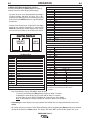
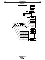
11. REMOTE RECEPTACLE – A 6-socket receptacle is
provided for the connection of an Amptrol, or other,
remote control: (See Figure B.2)
• When the Current Control Switch, (See Item 5), is in
the REMOTE position the Amptrol, or other remote
(10K pot), connected to the Remote receptacle controls the TIG or Stick mode output within the range
preset by the Maximum and Minimum Output controls. (See Item 6 and Item 7, also 8 for meter display)
• When the Current Control Switch is in either LOCAL
or REMOTE positions the arc start switch functions
when connected to the Remote receptacle.
FIGURE B.2
REMOTE RECEPTACLE *
(Front View)
ARC START
SWITCH
REMOTE OUTPUT
CONTROL
C
Max
D
B
E
A
10K ohm
Min
F
*For 18-12P Plug
(LECO S12020-27)
ADVANCED PANEL CONTROLS
The following controls are included only if the Precision
TIG 275 has the Advanced Control Panel (K2621-1)
option installed: (Refer to Section B-10 Tig Weld Cycle
Chart for graphic illustration of these TIG welding functions.)
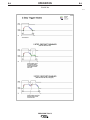
12. TRIGGER SWITCH – This 2-position switch
selects how the arc start switch ( connected to the
above Remote receptacle) functions; in 2-Step or 4Step mode:
CAUTION
• DO NOT USE 4-STEP IF USING AN AMPTROL
REMOTE.
• Neither the arc start switch nor the output control in the amptrol will function normally to shut
off or control the out put. ONLY USE 2-STEP.
-----------------------------------------------------------------------• In 2-Step position the arc start switch functions the
same as without the Advanced Panel:
1. Closing switch starts preflow, then a fixed
(0.5 sec.) ramp time from Minimum (Start)
setting level (See Item 7) to Weld setting.
2. Opening switch initiates Downslope ramp
time setting (See Item 17), from Weld setting to Crater-fill level (See Item 7), which
then stops the arc and initiates Postflow
time (See Item 9).
Note: See Section B-7 for 2-Step operation during
Downslope with Restart feature selected to be disabled, instead of enabled (as shipped).
PRECISION TIG 275
B-7
OPERATION
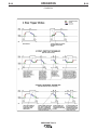
• In 4-Step position allows welding without continuously
holding the start switch trigger. The arc start switch functions in the following manner:
1. Closing switch starts preflow, then arc starts at
Minimum (Start) setting level (See Item 7). If the
trigger is maintained closed after preflow time the
output remains at the Start level until it is
released.
2. Opening switch initiates fixed (0.5 sec.) ramp
time from Start setting level to Weld setting.
3. Reclosing switch initiates Downslope ramp time
setting (See item 17) from Weld setting down to
the Crater-fill level (See Item 7) of the machine.
4. Reopening switch after Downslope time holds
Crater-fill level until switch opens, then stops the
arc and initiates the Postflow Time (See Item 9).
Or, reopening switch during Downslope time
immediately stops the arc and initiates the
Postflow.
Note: (See Internal Set Up Controls) for 4-Step operation
during Downslope with Restart feature selected to be
enabled, instead of disabled (as shipped).
B-7
15. PULSE % ON TIME/SPOT TIME CONTROL – This knob
sets the time for Pulse or Spot modes:
• % ON TIME sets duration of the peak current as a percentage (5% to 95% on white scale) of one pulse cycle.
The balance of the cycle time will be at the Background
Current setting. (See Item 16)
• SPOT TIME sets the duration of the Spot pulse (0.5 to 5.0
seconds on red scale).
16. PULSE BACKGROUND CURRENT CONTROL – This
knob controls the level of the Background Current as a
percentage (MIN.-100%) of the Peak (REMOTE and/or
LOCAL) output level (See Item 6) down to the Minimum
Output setting (See Item 7).
17. DOWNSLOPE TIME– This knob is used to set the time,
over the range of zero to about 10 seconds, to ramp
down from weld setting to Crater-fill level (See Item 7).
• If the arc goes out after the Downslope time is initiated,
the Downslope time is interrupted and the Postflow time is
initiated. This prevents Hi-Freq re-initiation during ramp
down crater fill
• When using an Amptrol remote control, where the downslope is controlled by the operator down to the crater-fill
level, the Downslope time should be set to zero so as not
to have the Downslope time delay when the arc start
switch is opened.
13. PULSE/SPOT MODE SWITCH – Turns on the Pulse
Mode as indicated by the Green panel light turning on.
• PULSE ON provides a Peak current level set by
REMOTE and/or LOCAL control of the output current (See
Item5), for a time determined by the Pulse Frequency
Control setting (See Item 14) and the % ON Time (See
Item 15). The balance of the cycle time is at the
Background Current level (See Item 16). The Green panel
light blinks at the pulse frequency and time setting rate.
• Pulsing begins after upslope when the output current rises
above the Background Current level and ends when the
output current drops below this level.
• SPOT ON mode provides the peak current level set by the
Maximum Output Control for a time determined by the
SPOT TIME control (see below). The red panel light is on
for Spot mode.
14. PULSE FREQUENCY CONTROL – This knob is used to
set the Pulse Frequency over the peak pulse range of
about 0.1 pps to 20 pps. (One pulse cycle time = 1/pps =
10 to .05 sec. range.)
PRECISION TIG 275
B-8
OPERATION
B-8
INTERNAL SET UP CONTROLS
TIG WELDING FEATURES
Precision TIG 275 models which have an Advanced
Panel (K2621-1) option installed* have the following
additional control features which are set up using the
DIP Switch (S1) provided on the internal panel of this
option.
The following DIP switch feature selections function
only when the Precision TIG is set to TIG mode (See
Item 3):
Access to this internal panel is obtained by removing
the two screws securing the top corners of the
Precision TIG front control panel and swinging the control panel down to reveal the panel mounted on the surface of the Precision TIG Control board:
ON – Doubles the time range.
OFF – Standard time range (as shipped).
CAUTION
• Switch #1 Postflow Time Extension* (See Item 9)
• Switch #2 2-Step Trigger Restart Feature (See
Figure B.3)
ON – Restart Enabled (as shipped).
OFF – Restart Disabled.
• THE CONTROL BOARDS CONTAIN STATIC SENSITIVE COMPONENTS
• To avoid possible damage to these components
be sure to ground yourself by touching the
machineʼs sheet metal while handling or making
settings on the internal control box components.
-----------------------------------------------------------------------PRECISION TIG ADVANCED PANEL
(M21115 Internal Panel)
• Switch #3 4-Step Trigger Restart Feature (See
Figure B.4)
ON – Restart Enabled.
OFF – Restart Disabled (as shipped)
• Switch #4 Lift TIG Starting - Does not function
(See Item 7a)
• Switch #5 Crater-Fill Level (See Item 7)
^ ON
1234567
ON - Level is minimum rating of the machine (2A)
OFF – Level (as shipped) is Minimum Output setting
(same as Start level).
DIP SWITCH (S1)
(DOES NOT FUNCTION)
S
HOT START
F
ARC FORCE
* The
Postflow Time doubling feature can also be selected on
Precision TIG 275 models without the Advanced Panel by accessing the Control board in the control box per above instructions,
then disconnecting the jumper terminals attached to the jumper
plug connected to receptacle J3 of the Control board. (Refer to
Machine Wiring Diagram.)
ON
1
2
3
4
5
6
7
OFF
DIP SWITCH POSITIONS (FACTORY SETTINGS)
STICK WELDING FEATURES
• Switch #6 Hot Start Level – Does not function
(See Item 7a)
• Switch #7 Arc Force Level – Does not function
(See Item 7a)
PRECISION TIG 275
B-9
OPERATION
FIGURE B.3
(With DIP Switch #2 OFF)
(With DIP Switch #2 ON, As Shipped)
PRECISION TIG 275
B-9
B-10
OPERATION
FIGURE B.4
(With DIP Switch #3 ON)
(With DIP Switch #3 OFF, As Shipped)
PRECISION TIG 275
B-10
B-11
B-11
OPERATION
TIG WELD CYCLE CHART
SEE ITEM 12
SEE ITEM 12
SEE ITEM 12
SEE ITEM 12
SEE ITEM 7a
SEE ITEM 6
SEE ITEM 6 & 7
SEE ITEM 7
SEE ITEM 15
SEE ITEM 14
SEE ITEM 7
SEE ITEM 15
SEE ITEM 7a
SEE ITEM 7a
SEE ITEM 16
SEE ITEM 17
SEE ITEM 12
SEE ITEM 9
SEE ITEM 12 & TIG
Welding Features
SETUP GUIDELINES FOR TIG WELDING
WITH AN AMPTROL
Both the Hand and Foot AMPTROLS work in a similar
manner. They are meant to be used for remote current
control for TIG welding using the machineʼs 2-Step
trigger mode (See Item 12).
The Amptrol is capable of controlling the output of the
Precision TIG over the range between the level preset
by the Minimum Output control when the Amptrol is at
its inactivated state, and the level preset by the
Maximum Output control when the Amptrol is at fullyactivated state.
It is important to note that even with the Precision TIGʼs
new MicroStartTM Technology, some tungstens may be
difficult to start at the low (2 amps) minimum rating of
the machine. Rather than guessing where to depress
the Amptrol to start the arc reliably, the Minimum
Output control allows presetting the exact level, so
reliable starts, as well as minimum crater-fill levels, can
be consistently obtained at the minimum Amptrol (inactivated ) state. FIGURE B.6 shows Precision TIG setup
for TIG welding with an Amptrol.
PRECISION TIG 275
B-12
B-12
OPERATION
FIGURE B.6
Setup f or TIG Amptrol Weld ing
Standa rd Controls
Power Switch
ON
Mode Switch
TIG
Polar ity S witc h
AC or DC-
AC Balance
AUTO
or
Set:
More +
for alum.oxide "Cleaning"
w/o "Sp
itting" or
"wetting" loss.
Balanced for equal + and - current.
More r higher
fo
"Penetration".
Local/R emote
Switc h
REMOTE
Maximum O utput
Set to desired max.
Amptrol output level.
Minimum O utput
Min. to Max.
Amptrol
Max. to Min.
Amptrol
Press Display switch
and Set to desired min.
Amptrol (Start/Crater)
output level.
Postfl ow
Set as low as required.
Higher for larger
tungsten and current.
Ad vanced P anel
(If us ed)
Trigge r Switch
2-STEP
Pulse Freque ncy
4-6 pps is a typical initial setting.
Set for bead shape and travel speed:
Higher for thinner plate and faster travel.
Lower for thicker plate and slower travel.
Pulse S witch
ON
or
OFF
% On Time
40-60% is a typical initial setting.
Set for total heat of Peak current:
Lower reduces distortion and burn-thru.
Backgr ound Cu rre nt
40-60% is a typical initial setting.
Set as low as will maintain a pulse arc
(Will not drop below Min.Output setting.)
PRECISION TIG 275
Downslope
ZERO
For no arc-out delay.
B-13
B-13
OPERATION
Close the arc start switch. This opens the gas valve
to automatically purge air from the hose and torch,
then shields the arc strike area. After the 0.5 second preflow time, the high frequency becomes
available to strike the arc. When the arc strikes the
torch coolant (if used) starts to flow. Also, if welding
DC- TIG, the high frequency shuts off just after the
arc strikes.
MAKING A TIG WELD WITH AN AMPTROL
1. Install welding equipment per Section A-5.
2. Setup controls per Section B-10.
3. Turn on the shielding gas supply, and torch coolant
input supply (if used).
Note: The Precision TIG Under-Cooler (or Water
Solenoid connected to the Cooler receptacle) runs with
the Fan-As-Needed machine cooling fan (See
Maintenance Section D), so the cooler fan and water
pump will also not run continuously in idle, but will run
while welding.
4. With the torch held safely away from everything,
close the Arc Start Switch of the Amptrol and set the
gas flow meter. Then open the switch. The welder
is now ready for welding.
5. Position the tungsten electrode at the start of the
weld at a 65° to 75° angle with the horizontal, in the
direction of pushing travel, so that the electrode is
approximately 1/8" (4 mm) above the work piece.
6. Hold the arc start switch closed at minimum Amptrol
Start level (See Section B-10) until an arc is established, then increase the output to the desired welding level and push the torch in the direction of travel.
7. At the end of the weld, decrease the Amptrol output
to the crater-fill level before releasing the arc start
switch to start the Postflow time. Hold the torch gas
shielding over the solidifying weld crater while postflow time expires and the gas valve reopens. The
torch coolant (if used) continues to flow for up to 8
minutes after the arc goes out (with the Fan-AsNeeded feature) to assure torch cooling.
• Repeat steps 5 through 7 to make another weld.
RECOMMENDED ELECTRODE AMPERAGE RANGES - PRECISION TIG 275
ELECTRODE
Fleetweld 5P, Fleetweld 5P+
Fleetweld 180
Fleetweld 37
Fleetweld 47
Jet-LH MR
Blue Max Stainless
Red Baron Stainless
POLARITY
DC+
DC+
DC+
DCDC+
DC+
DC+
SMAW Process
3/32"
40 - 70
40 - 80
70 - 95
75 - 95
85 - 110
40 - 80
40 - 70
1/8"
75 - 130
55 - 110
100 - 135
100 - 145
110 - 160
75 - 110
60 - 100
5/32"
90 - 175
105 - 135
145 - 180
135 - 200
130 - 220
95 - 110
90 - 140
Mild steel procedures are based on recommended procedures listed in C2.10 8/94 and the maximum rating of the PRECISION TIG 275
Excaliber 7018 procedures are based on Jet-LH 78 MR
Blue Max procedures are based on C6.1 6/95
Red Baron Procedure are based on ES-503 10/93
Electrode Polarity
Electrode Tip Preparation
Electrode Type
Electrode Size (in.)
.010
.020
.040
1/16
3/32
1/8
*
DCSharpened
EWTh-1, EWCe-2
EWTh-2, EWLa-1
EWG
Up to 15 A.
Up to 15 A.
Up to 80 A.
Up to 150 A.
Up to MAX. A.
X
GTAW Process
AC*
Balled
EWP
Up to 15 A.
10 to 15 A.
20 to 30 A.
30 to 80 A.
60 to 130 A.
100 to 180 A.
EWZr
EWTh-1, EWTh-2
EWCe-2, EWLa-1
EWG
Up to 15 A.
5 to 20 A.
20 to 60 A.
60 to 120 A.
100 to 180 A.
160 to 250 A.
Tungsten electrodes are classified as follows by the American Welding Society (AWS):
Pure .........................................EWP...........green
+1% Thoria ..............................EWTh-1......yellow
+2% Thoria ..............................EWTh-2......red
+2% Ceria................................EWCe-2 .....orange
+1.5% Lanthana ......................EWLa-1 ......black
+0.15 to 0.40% Zirconia ..........EWZr..........brown
Ceriated Tungsten is now widely accepted as a substitute for 2% Thoriated Tungsten in AC and DC applications.
Balanced Wave, Unbalanced Wave requires derating of the electrode.
PRECISION TIG 275
Approximate Argon
Gas Flow Rate
C.F.H. (l/min.)
Aluminum
3-8
(2-4)
5-10
(3-5)
5-10
(3-5)
5-10
(3-5)
13-17 (6-8)
15-23 (7-11)
Stainless
Steel
3-8
(2-4)
5-10 (3-5)
5-10 (3-5)
9-13 (4-6)
11-15 (5-7)
11-15 (5-7)
C-1
ACCESSORIES
C-1
• K870 Foot Amptrol
Single pedal foot activation of arc start switch and
output control, with 25ʼ plug cable.
OPTIONAL EQUIPMENT
FACTORY INSTALLED OPTIONS
The basic Precision TIG 275 machine is factory
equipped with:
• A 3/8" Adapter (S20403-4) for air cooled torch connection of a PTA-9 or PTA-17.
Accessories that are factory installed with the
Domestic model (K2619-1) to make up the Domestic
Welding Package (K2618-1) include:
• K1828-1
• 3100211
Under-Cooler Cart
Harris Argon Flow Regulator with 10ʼ
hose.
• K870 Foot Amptrol
• K1784-4
25ʼ PTW-20 water-cooled TIG Torch
• K918-2
Zippered Torch Cover
• KP510
Parts Kit for Torch
• K2150-1
Work Lead Assembly
See below for more detailed descriptions.
FIELD INSTALLED OPTIONS
The following Options/Accessories are available for the
Precision TIG 275 and are installed per instructions in
this manual and / or provided in the package:
• K2621-1 Precision TIG Advanced Control Panel
Provides 2/4-step trigger modes with
adjustable Pulser/Spot controls and Down
slope timer for TIG welding. Also allows
adjustable Hot Start and Arc Force Menu
settings for Stick welding and Menu settings for TIG Hot Start and Upslope, as well
as other user selectable features.
• K1828-1 Under-Cooler Cart
Includes a "cooler-in-a-drawer" with hoses and a
lockable storage drawer on a dual bottle undercarriage (see below).
• K963-3 Hand Amptrol
Fastens to torch for convenient thumb activation of
arc start switch and output control, with 25ʼ plug
cable:
• K814 Arc Start Switch
Needed for TIG welding without an Amptrol. Includes
25ʼ plug cable, and attaches to torch for convenient
finger control.
• K1831-1 Power Factor Capacitor Kit
Used when welding at higher output currents to
reduce input current and help keep electricity costs
to a minimum.
• Magnum® PTA and PTW Series Torches
All Air Cooled or Water-Cooled Magnum® TIG
Torches may be used with the PRECISION TIG 275.
Connection adapters are only required for Air-Cooled
Torches (Refer to Diagrams on A-7):
K2166-1 7/8” Torch Connector for PTA-26 (one
piece)
K2166-2 1/2” stud Connector for PTA Torch (twopiece).
K2166-3 3/8” TIG Torch Connector for PTA-9,-17
(one piece). (Included as S20403-4 with Precision
TIG models.)
• 3100211 Harris Argon Flow Regulator (Includes 10ʼ
hose.)
• K2150-1 Work Lead Assembly
15ft. 2/0 cable with 1/2" stud lug and work clamp.
• K1869-1 Undercarriage
Includes a dual bottle rack with chain and an undercarriage with 5" front casters,10" rear wheels and a
handle.
• K1830-1 Water Solenoid Kit
Provides for stopping flow of external water supply.
Connects to coolant inlet and cooler receptacle of
Precision TIG.
(Can not be used with a water cooler.)
PRECISION TIG 275
D-1
MAINTENANCE
SAFETY PRECAUTIONS
D-1
OVERLOAD PROTECTION
FAN-AS-NEEDED (F.A.N.)
WARNING
ELECTRIC SHOCK can kill.
• Only qualified personnel should
perform this maintenance.
• Turn the input power OFF at the
disconnect switch or fuse box
before working on this
equipment.
• Do not touch electrically hot
parts.
WARNING
To avoid receiving a high frequency shock, keep the
TIG torch and cables in good condition.
ROUTINE AND PERIODIC MAINTENANCE
Very little routine maintenance is necessary to keep
your Precision TIG 275 running in top condition. No
specific schedule can be set for performing the following items; factors such as hours of usage and machine
environment should be considered when establishing
a maintenance schedule.
• Periodically blow out dust and dirt which may accumulate within the welder using an air stream.
• Inspect welder output and control cables for fraying,
cuts, and bare spots.
• Inspect the spark gap at regular intervals to maintain
the recommended spacing. See the Service
Procedures (See Service Procedures in this
Section) for complete information on spark gap settings.
• The fan motor has sealed ball bearings which
require no maintenance.
Overload Protection
The Precision TIG 275 has the F.A.N. circuit feature,
which means the cooling fan will operate only while
welding; then for about 8 minutes after welding has
stopped to assure proper machine cooling. This helps
reduce the amount of dust and dirt drawn into the
machine with the cooling air. The cooling fan will operate briefly when the machine power is initially turned
on, and continuously while the yellow Thermal
Shutdown Light is lit (see Thermostatic Protection).
THERMOSTATIC PROTECTION
This welder has thermostatic protection from excessive
duty cycles, overloads, loss of cooling, and excessive
ambient temperatures. When the welder is subjected
to an overload, or inadequate cooling, the primary coil
thermostat and/or secondary coil thermostat will open.
This condition will be indicated by the illumination of
the yellow Thermal Shutdown Light on the front panel
(see Item 10 in Section B). The fan will continue to run
to cool the power source. Postflow occurs when TIG
welding is shut down, but no welding is possible until
the machine is allowed to cool and the yellow Thermal
Shutdown Light goes out.
AUXILIARY POWER CIRCUIT BREAKER
The 115vac auxiliary circuits and rear receptacle (see
Section A Auxiliary Power Connections) are protected
from overloads by a 15 amp circuit breaker, located
above the receptacle. If the breaker trips its button
pops out exposing a red ring. When the circuit breaker
cools the button can be reset by pressing it back in.
Note: When the breaker trips not only will the receptacleʼs auxiliary and cooler power be interrupted, but so
will the power to the shielding gas solenoid and
machine cooling fan.
The Export models also include a 5 amp circuit breaker, located on the opposite side of the upper case back,
for protection of the 220vac Schuko type cooler receptacle.
PRECISION TIG 275
D-2
D-2
MAINTENANCE
FIGURE C.1 SPARK GAP
SERVICE PROCEDURES
Operation of the Precision TIG should be trouble-free
for the life of the machine. Should a malfunction occur,
however, the following procedures will be useful to
trained service personnel with experience in repairing
arc welding equipment:
.015 Spark Gap
COMPONENT ACCESS
The following components are accessible for routine
set up and periodic service without requiring removal
of the case sides or roof:
• Input Reconnect Panel (refer Section A) is located
behind a removable panel on the rear of the left case
side. Remove the two screws (with a screwdriver or
a 3/8"/ 9.5mm hex driver) on the bottom corners of
this panel to remove it.
• Control Box components and PC Boards (refer
Section B Internal Set Up Controls) are located
behind the front control panel. Remove the two
screws (with a screwdriver or a 3/8"/ 9.5mm hex driver) on the top corners of this panel to swing it down.
• Hi-Freq. Spark Gap assembly (refer Spark Gap
Adjustment) is located behind a removable panel on
the rear of the right case side, under the torch box.
Remove the screw (with a screwdriver or a 3/8"/
9.5mm hex driver) on the bottom center of this panel
to remove it.
Note: In highly dirty environments where there is an
abundance of conductive contaminants, use a low
pressure air stream or a firm piece of paper to clean
out the spark gap. Do not disturb the factory gap setting.
To check the spark gap:
1. Turn the input power off per above.
2. Remove the access panel on the right case side
(See Component Access).
3. Check the spark gap spacing with a feeler gauge.
If adjustment is required:
1. Adjust the gap by loosening the Allen head screw
on one of the aluminum blocks, reset the gap and
tighten the screw in the new position.
If spark gap is correct:
1. Reinstall the access panel on the right case side.
SPARK GAP ADJUSTMENT
The spark gap is set at the factory to a gap of 0.015
inches (0.4 mm) See Figure C.1. This setting is adequate for most applications. Where less high frequency is desired, the setting can be reduced to 0.008 inches (0.2 mm).
WARNING
Use extreme caution when working with circuit of
the high frequency. The high voltages developed
can be lethal. Turn the input power off using the
disconnect switch or fuse box before working
inside the machine. This is particularly important
when working on the secondary circuit of the high
voltage transformer (T3) because the output voltage is dangerously high.
------------------------------------------------------------------------
PRECISION TIG 275
D-3
MAINTENANCE
METER CALIBRATION ADJUSTMENT
The Precision TIG meter circuits are factory calibrated
for the accuracy of the ammeter and voltmeter (see
Section B Panel Control Functions), and should not
need adjustment. However, the factory trimmers are
accessible inside the control box (see Section D
Component Access):
• The Meter Board, located on the front panel of the
machine, is digital and has no calibration capability.
• Ammeter Calibration Trimmer (R5) is located on
the Control PC Board (left of center near the top of
the board). This trimmer adjusts calibration of the
ammeter circuit to the digital panel Meter, so it should
be checked after the Digital Meter check above. The
ammeter calibration is checked as follows:
1. Set to TIG mode with DC- polarity and
LOCAL control. Without closing the arc start
switch, preset the Maximum Output panel
control so the panel digital Meter reads
about 200 amps.
D-3
3. Using a DC (avg.) test voltmeter with at
least 1% accuracy at up to 100 volts, connect it across the WORK (+) and ELECTRODE (-) studs on the front stud panel.
Remove the TIG torch, if connected.
4. Press the DISPLAY panel switch to V (volts)
position, then close the arc start switch just
long enough* to compare the panel Meter
reading to that of the test volt meter. The
open circuit voltage readings (about 50vdc)
should match within 3%+/-1V. If not, adjust
the trimmer so that the panel meter accuracy is corrected.
* If switch is held closed longer than about 15 seconds
the Precision TIG will shut down to protect internal
holding resistor from overheating.
UNDER-COOLER SERVICE
The required maintenance and service instructions for
the Under-Cooler are provided in the operatorʼs manual (IM723) provided with the Under-Cooler Cart.
2. Using a DC (avg.) test ammeter with at least
1% accuracy at up to 300 amps, connect it
to measure the DC current through a short
weld cable shorting out the WORK (+) to
ELECTRODE (-) studs on the front stud
panel. Remove the TIG torch, if connected.
3. Close the arc start switch just long enough
to compare the panel Meter reading to that
of the test ammeter. The short circuit current
readings should match within 4%+/-2A. If
not, adjust the trimmer so that the panel
meter accuracy is corrected.
• Voltmeter Calibration Trimmer (R2) is located on
the Control PC Board (right of center near the top of
the board). This trimmer adjusts calibration of the
voltmeter circuit to the digital panel Meter, so it
should be checked after the Digital Meter check
above. The voltmeter calibration is checked as follows:
1. To prevent maximum OCV output (which is
not precise for voltmeter checking) disconnect the SCR gate lead plug from receptacle J4 on the lower left corner of the Control
PC board.
2. Set to TIG mode with DC- polarity without
closing the arc start switch.
PRECISION TIG 275
E-1
TROUBLESHOOTING
E-1
HOW TO USE TROUBLESHOOTING GUIDE
WARNING
Service and Repair should only be performed by Lincoln Electric Factory Trained Personnel.
Unauthorized repairs performed on this equipment may result in danger to the technician and machine
operator and will invalidate your factory warranty. For your safety and to avoid Electrical Shock, please
observe all safety notes and precautions detailed throughout this manual.
__________________________________________________________________________
This Troubleshooting Guide is provided to help you
locate and repair possible machine malfunctions.
Simply follow the three-step procedure listed below.
This column provides a course of action for the
Possible Cause, generally it states to contact your
local Lincoln Authorized Field Service Facility.
Step 1. LOCATE PROBLEM (SYMPTOM).
Look under the column labeled “PROBLEM (SYMPTOMS)”. This column describes possible symptoms
that the machine may exhibit. Find the listing that best
describes the symptom that the machine is exhibiting.
If you do not understand or are unable to perform the
Recommended Course of Action safely, contact your
local Lincoln Authorized Field Service Facility.
Step 2. POSSIBLE CAUSE.
The second column labeled “POSSIBLE CAUSE” lists
the obvious external possibilities that may contribute to
the machine symptom.
Step 3. RECOMMENDED COURSE OF ACTION
CAUTION
DO NOT use a volt-ohm meter to measure output voltages in TIG mode. The
High Frequency Arc Starter voltage can damage the meter.
CAUTION
If for any reason you do not understand the test procedures or are unable to perform the tests/repairs safely, contact your Local
Lincoln Authorized Field Service Facility for technical troubleshooting assistance before you proceed.
PRECISION TIG 275
E-2
E-2
TROUBLESHOOTING
Observe all Safety Guidelines detailed throughout this manual
PROBLEMS
(SYMPTOMS)
POSSIBLE
CAUSE
RECOMMENDED
COURSE OF ACTION
OUTPUT PROBLEMS
Thermal light comes on
1. Thermal shut down. Dirt and dust
may have clogged the cooling
channels inside machine; air
intake and exhaust louvers may
be blocked; welding application
may exceed recommended duty
cycle. Wait until machine cool
down and thermal light goes out.
Blow out machine with clean, dry
low pressure air; check air intake
and louvers; stay within recommended duty cycle.
2. Bad thermostat or its connections
Meter doesnʼt light up
1. Losing AC supply to Control PC
board
2. Loosing input to machine
If all recommended possible areas
of misadjustment have been
No gas & no hi-freq 1. Faulty trigger or hand/foot Amptrol checked and the problem persists,
Contact
your
local
Lincoln
or connections.
Authorized Field Service Facility.
2. Faulty Protection PC board or
bad connection to Control PC
board
3. Faulty Control PC board
Has output in
Stick mode
but no output
in Tig mode
3. Losing trigger supply to Control
PC board
Gas & hi-freq are o.k. 1. Faulty Control PC board
No output in both Stick and Tig
modes
1. Bad connection at P4 of Control
PC board
2. Faulty Control PC board
CAUTION
If for any reason you do not understand the test procedures or are unable to perform the tests/repairs safely, contact your Local
Lincoln Authorized Field Service Facility for technical troubleshooting assistance before you proceed.
PRECISION TIG 275
E-3
E-3
TROUBLESHOOTING
Observe all Safety Guidelines detailed throughout this manual
PROBLEMS
(SYMPTOMS)
POSSIBLE
CAUSE
RECOMMENDED
COURSE OF ACTION
METER PROBLEMS
Meter does not light up
1. Bad meter or its connection.
2. Bad connection at P13 of Control
PC board.
3. Faulty Control PC board.
Meter does not display V (Volt) or
Min A (Minimum current)
1. Bad Display switch or its connection.
If all recommended possible areas
of misadjustment have been
checked and the problem persists,
Contact
your
local
Lincoln
Authorized Field Service Facility.
2. Bad connection at P9 of Control
PC board.
GAS PROBLEMS
No gas
1. Circuit breaker CB1 open. Press
CB1 in to reset.
2. Bad connection at P12 of Control
PC board.
3. Faulty gas solenoid valve SV1 or
its connection.
4. Faulty Control PC board.
No control on post flow time
1. Faulty potentiometer R3 or its
connection.
If all recommended possible areas
of misadjustment have been
checked and the problem persists,
your
local
Lincoln
1. For Postflow; the DIP switch set- Contact
Authorized
Field
Service
Facility.
ting on the Advanced Control PCB
(if installed) may be set for time x2.
Check DIP switch setting.
2. Bad connection at P9 of Control
PC board.
Pre flow & Post flow time too long
2. For Preflow; Menu setting too
long. Check Menu setting.
3. Missing plug P3 on Control board
or bad connection of P3 to
Advanced Control PCB.
CAUTION
If for any reason you do not understand the test procedures or are unable to perform the tests/repairs safely, contact your Local
Lincoln Authorized Field Service Facility for technical troubleshooting assistance before you proceed.
PRECISION TIG 275
E-4
E-4
TROUBLESHOOTING
Observe all Safety Guidelines detailed throughout this manual
PROBLEMS
(SYMPTOMS)
POSSIBLE
CAUSE
RECOMMENDED
COURSE OF ACTION
HI-FREQ PROBLEMS
No hi-freq
1. Circuit breaker CB1 open
2. Bad connection at P12 of Control
PC board
3. Spark gaps shorted
4. Faulty Control PC board
Hi-freq intensity too weak
1. Dirty spark gap or improper gap
setting
2. Faulty Arc Starter assembly
Hi-freq on continuously in DC Tig
Hi-freq shuts off after starting in AC
Tig
1. Bad connection at P11 of Control
PC board
2. Micro-switch S2A is not engaged &
disengaged properly when switching between DC & AC polarity.
(S2A locates on the Polarity
If all recommended possible areas
switch)
of misadjustment have been
checked and the problem persists,
3. Faulty Control PC board
Contact
your
local
Lincoln
1. Micro-switch S2A is not engaged & Authorized Field Service Facility.
disengaged properly when switching between DC & AC polarity.
(S2A locates on the Polarity
switch)
CAUTION
If for any reason you do not understand the test procedures or are unable to perform the tests/repairs safely, contact your Local
Lincoln Authorized Field Service Facility for technical troubleshooting assistance before you proceed.
PRECISION TIG 275
E-5
E-5
TROUBLESHOOTING
Observe all Safety Guidelines detailed throughout this manual
PROBLEMS
(SYMPTOMS)
POSSIBLE
CAUSE
RECOMMENDED
COURSE OF ACTION
PRESET & OUTPUT CONTROL PROBLEMS
Meter does not display preset
1. Faulty potentiometer R1 or its connection
2. Bad connection at P9 of Control
PC board
3. Faulty Advanced Control PC board
( if present ) or its connection to
the main Control PC board
4. Missing plug P3 on Control board
or bad connection at P3 when an
Advanced Control PC board is not
present
High output current in both DC & AC 1. Bad connection at P6 of Control
PC board
polarities regardless of preset
2. Bad shunt connection
3. Faulty Control PC board
4. Faulty SCR bridge
High output current in DC polarity 1. Shorted free wheeling diode D1
regardless of preset, o.k. in AC polarity
If all recommended possible areas
of misadjustment have been
checked and the problem persists,
Contact
your
local
Lincoln
Authorized Field Service Facility.
In 2-step Tig, output stays on for 1. Bad 2/4 step switch or its connection
more than downslope time after trigger open (machine with Advanced
2. Bad connection at P1 of Advanced
Control panel only)
Control PC board
Output stays on after releasing 1. Downslope is not set at min.
hand/foot Amptrol (machine with
2. Bad Downslope potentiometer
Advanced Control panel only)
R12 or its connection
CAUTION
If for any reason you do not understand the test procedures or are unable to perform the tests/repairs safely, contact your Local
Lincoln Authorized Field Service Facility for technical troubleshooting assistance before you proceed.
PRECISION TIG 275
E-6
E-6
TROUBLESHOOTING
Observe all Safety Guidelines detailed throughout this manual
PROBLEMS
(SYMPTOMS)
POSSIBLE
CAUSE
RECOMMENDED
COURSE OF ACTION
STICK WELDING PROBLEMS
Stick electrode "blast off" when arc
is struck
1. Current may be set too high for
electrode size
Stick electrode "sticks" in the weld
puddle
2. (Machine with Advanced Control If all recommended possible areas
PC board only) Hot Start Menu of misadjustment have been
setting too high
checked and the problem persists,
Contact
your
local
Lincoln
1. Current may be set too low for Authorized Field Service Facility.
electrode size
2. (Machine with Advanced Control
PC board only) Arc Force Menu
setting too low
TIG WELDING PROBLEMS
Poor starting in DC polarity
1. Input line may be too low
2. Bad connection at P11 of Control
PC board
3. Bad Background rectifier, background resistor R7, or background
diode D2
Arc "flutters" in DC polarity, o.k. in
AC polarity
1. Tungsten not "sharp"
2. Bad free wheeling diode D1 or its
connection
If all recommended possible areas
of misadjustment have been
Arc "flutters" in both DC & AC polari- 1. Tungsten electrode may be too checked and the problem persists,
large in diameter for the current Contact
ties
your
local
Lincoln
setting
Authorized Field Service Facility.
2. Gas shielding may be insufficient.
3. Contaminated gas or leaks in the
gas line, torch, or connections
4. Helium blend is used as a shielding gas
CAUTION
If for any reason you do not understand the test procedures or are unable to perform the tests/repairs safely, contact your Local
Lincoln Authorized Field Service Facility for technical troubleshooting assistance before you proceed.
PRECISION TIG 275
E-7
E-7
TROUBLESHOOTING
Observe all Safety Guidelines detailed throughout this manual
PROBLEMS
(SYMPTOMS)
POSSIBLE
CAUSE
RECOMMENDED
COURSE OF ACTION
TIG PROBLEMS
Arc "pulsates" in AC polarity, DC 1.Micro switch S2A on polarity switch
polarity is o.k.
does not open in AC polarity
Black area along weld bead
1. Oily or organic contamination from
work piece
2. Tungsten electrode may be contaminated
3. Leaks in gas line, torch, or connections
Output quits momentarily; gas flow 1. May be caused by hi-freq interferand hi-freq are also interrupted
ence. Check that machine is
grounded properly. Surrounding
machines that generate hi-freq
also should be properly grounded.
2. Ground connection of Protection
PC board may has become loose
3. Ground
connection
of If all recommended possible areas
Bypass/Stabilizer PC board may of misadjustment have been
checked and the problem persists,
has become loose.
Contact
your
local
Lincoln
Authorized Field Service Facility.
CAUTION
If for any reason you do not understand the test procedures or are unable to perform the tests/repairs safely, contact your Local
Lincoln Authorized Field Service Facility for technical troubleshooting assistance before you proceed.
PRECISION TIG 275
NOTE: This diagram is for reference only. It may not be accurate for all machines covered by this manual. The specific diagram for a particular code is pasted
inside the machine on one of the enclosure panels. If the diagram is illegible, write to the Service Department for a replacement. Give the equipment code number..
F-1
WIRING DIAGRAM
PRECISION TIG 275
F-1
NOTE: This diagram is for reference only. It may not be accurate for all machines covered by this manual. The specific diagram for a particular code is pasted
inside the machine on one of the enclosure panels. If the diagram is illegible, write to the Service Department for a replacement. Give the equipment code number..
F-2
WIRING DIAGRAM
PRECISION TIG 275
F-2
DIMENSION PRINT
K2618-1 DOMESTIC PACKAGE
F-3
PRECISION TIG 275
F-3
DIMENSION PRINT
K2619-1 DOMESTIC, K2619-2 CANADA
F-4
PRECISION TIG 275
F-4
NOTES
PRECISION TIG 275
NOTES
PRECISION TIG 275
● Do not touch electrically live parts or
WARNING
Spanish
AVISO DE
PRECAUCION
French
ATTENTION
German
WARNUNG
Portuguese
ATENÇÃO
● Keep flammable materials away.
● Wear eye, ear and body protection.
● Mantenga el material combustible
● Protéjase los ojos, los oídos y el
electrode with skin or wet clothing.
● Insulate yourself from work and
ground.
● No toque las partes o los electrodos
bajo carga con la piel o ropa mojada.
● Aislese del trabajo y de la tierra.
● Ne laissez ni la peau ni des vête-
ments mouillés entrer en contact
avec des pièces sous tension.
● Isolez-vous du travail et de la terre.
● Berühren Sie keine stromführenden
Teile oder Elektroden mit Ihrem
Körper oder feuchter Kleidung!
● Isolieren Sie sich von den
Elektroden und dem Erdboden!
● Não toque partes elétricas e elec-
trodos com a pele ou roupa molhada.
● Isole-se da peça e terra.
fuera del área de trabajo.
● Gardez à l’écart de tout matériel
inflammable.
● Entfernen Sie brennbarres Material!
cuerpo.
● Protégez vos yeux, vos oreilles et
votre corps.
● Tragen Sie Augen-, Ohren- und Kör-
perschutz!
● Mantenha inflamáveis bem guarda-
dos.
● Use proteção para a vista, ouvido e
corpo.
Japanese
Chinese
Korean
Arabic
READ AND UNDERSTAND THE MANUFACTURER’S INSTRUCTION FOR THIS EQUIPMENT AND THE CONSUMABLES TO
BE USED AND FOLLOW YOUR EMPLOYER’S SAFETY PRACTICES.
SE RECOMIENDA LEER Y ENTENDER LAS INSTRUCCIONES DEL FABRICANTE PARA EL USO DE ESTE EQUIPO Y LOS
CONSUMIBLES QUE VA A UTILIZAR, SIGA LAS MEDIDAS DE SEGURIDAD DE SU SUPERVISOR.
LISEZ ET COMPRENEZ LES INSTRUCTIONS DU FABRICANT EN CE QUI REGARDE CET EQUIPMENT ET LES PRODUITS A
ETRE EMPLOYES ET SUIVEZ LES PROCEDURES DE SECURITE DE VOTRE EMPLOYEUR.
LESEN SIE UND BEFOLGEN SIE DIE BETRIEBSANLEITUNG DER ANLAGE UND DEN ELEKTRODENEINSATZ DES HERSTELLERS. DIE UNFALLVERHÜTUNGSVORSCHRIFTEN DES ARBEITGEBERS SIND EBENFALLS ZU BEACHTEN.
● Keep your head out of fumes.
● Use ventilation or exhaust to
● Turn power off before servicing.
● Do not operate with panel open or
guards off.
remove fumes from breathing zone.
● Los humos fuera de la zona de res-
piración.
● Mantenga la cabeza fuera de los
humos. Utilice ventilación o
aspiración para gases.
● Gardez la tête à l’écart des fumées.
● Utilisez un ventilateur ou un aspira-
● Desconectar el cable de ali-
mentación de poder de la máquina
antes de iniciar cualquier servicio.
● Débranchez le courant avant
l’entretien.
teur pour ôter les fumées des zones
de travail.
● Vermeiden Sie das Einatmen von
Schweibrauch!
● Sorgen Sie für gute Be- und
Entlüftung des Arbeitsplatzes!
● Mantenha seu rosto da fumaça.
● Use ventilação e exhaustão para
remover fumo da zona respiratória.
● Strom vor Wartungsarbeiten
● No operar con panel abierto o
guardas quitadas.
● N’opérez pas avec les panneaux
ouverts ou avec les dispositifs de
protection enlevés.
● Anlage nie ohne Schutzgehäuse
abschalten! (Netzstrom völlig öffnen; Maschine anhalten!)
oder Innenschutzverkleidung in
Betrieb setzen!
● Não opere com as tampas removidas.
● Desligue a corrente antes de fazer
● Mantenha-se afastado das partes
serviço.
● Não toque as partes elétricas nuas.
moventes.
● Não opere com os paineis abertos
ou guardas removidas.
WARNING
Spanish
AVISO DE
PRECAUCION
French
ATTENTION
German
WARNUNG
Portuguese
ATENÇÃO
Japanese
Chinese
Korean
Arabic
LEIA E COMPREENDA AS INSTRUÇÕES DO FABRICANTE PARA ESTE EQUIPAMENTO E AS PARTES DE USO, E SIGA AS
PRÁTICAS DE SEGURANÇA DO EMPREGADOR.
• World's Leader in Welding and Cutting Products •
• Sales and Service through Subsidiaries and Distributors Worldwide •
Cleveland, Ohio 44117-1199 U.S.A. TEL: 216.481.8100 FAX: 216.486.1751 WEB SITE: www.lincolnelectric.com