1
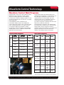
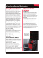
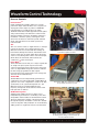
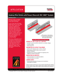
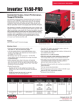
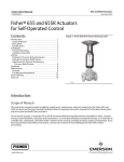
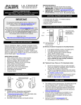
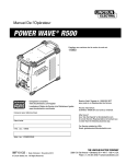
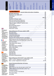
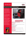
TECHNOLOGY
W A V E F O R M
C O N T R O L
T E C H N O L O G Y
T M
Waveform Control TechnologyTM
Just as computer companies
recognize the importance of
providing their customers with
multi-functional equipment,
Lincoln Electric realizes that our
customers want the power to
choose what fits them best. As
companies broaden their product
offerings, this desire has turned
into necessity.
In the past, different equipment
has been required for different
welds. Customers often needed
several models of welding
equipment to perform a variety of
welding procedures.
Waveform Control Technology
revolutionizes the way welding
equipment is chosen. Waveform
Control Technology welding
systems support 8 processes,
over 80 weld procedures, and the
option to fine-tune or develop new
welding programs. Waveform
Control Technology is available
in semi-automatic, hard
automation, or robotic systems.
We’ve put the power of choice
back into the hands of the
operators. Choose wisely. Choose
Waveform Control Technology.
Alterations to the waveform can be made during the weld,
using software created by Lincoln Electric.
SIMPLIFIED PROCESS SELECTION
Metal transfer modes may be controlled to extend the stable operating range
of the welding process.
ADAPTABILITY
Shapes the arc using computer software. A single machine can quickly and
easily adapt to:
• A wide range of applications
• Varying materials specifications
• Varied weld positions
• Appearance requirements
WELD QUALITY
Optimized metal transfer reduces spatter and improves arc stability.
PRODUCTIVITY
Higher deposition rates are possible at heat input equal to or less than
traditional CV processes.
CUSTOMIZABLE
Output parameters may be adjusted for given welding waveform conditions
and joint design to meet weld specifications and production rates.
T
h
e
f
u
t
u
r
e
o
f
w
e
l
d
i
n
g
i
s
h
e
r
e .®
NX-1.10 11/03
TECHNOLOGY
Waveform Control Technology
2/8
What
is Waveform Control?
Waveform Control Technology
is the ability to customize
waveform output. It is the ability
to choose a weld program from
a pre-defined set of programs,
and to manipulate the
parameters of that program
to best fit your application.
Lincoln Electric strives to
understand the customer’s
needs in order to make the job
easier. That is why Waveform
Control Technology was
designed: to empower the
people who use the equipment,
our customers.
The Arc Action Tool shows the behavior of the arc in the form of a Voltage/Amperage
(VI) plot. To further illustrate what the changes in voltage and current mean to the arc,
Lincoln Electric uses high-speed photography to capture arc behavior.
Waveform Control Technology
allows the user to choose from
a library of pre-programmed
weld “modes” that have been
developed by expert welders.
Then, Waveform Control
Technology offers the
opportunity to change those
values, within a programmed range,
to find the combination of wire feed
speed, voltage, current, and arc
control that the application requires.
to use a single source to perform
Stick, TIG, MIG/MAG, Flux-cored,
and Submerged Arc welding
procedures. With a Waveform
Control Technology product, the
days of configuring different systems
to make different welds are over.
But Lincoln has even taken it one
step further. Waveform Control
Technology also provides the ability
How
Waveform Control Works
There are many physical forces that affect the welding arc and the transfer of metal from the electrode to the
weld puddle. Surface tension, magnetic, and aerodynamic forces are the most significant. The welding current
directly affects the magnetic and aerodynamic forces in the welding arc. The welding current and surface tension
forces can be balanced to control metal transfer within the arc.
Amperage
High-speed electronics monitor the electrical signals
from the welding arc and make appropriate changes
to the current waveform. The electronics must be
fast, accurate, and rugged to control the arc and
withstand the harsh welding environment.
T
h
e
f
u
t
u
r
e
o
f
w
e
l
d
i
n
g
i
s
h
e
r
e .®
TECHNOLOGY
Waveform Control Technology
3/8
Waveform Control Weld Programs
Equipped with our most up-to-date welding programs,
Waveform Control Technology systems suit the
majority of welding applications. The flexibility of
choosing from a variety of welding programs not only
increases productivity, but also promotes consistently
high-quality welds.
The programs listed in the following tables were
developed by Lincoln Electric.* It is important to note
that, although we attempted to provide a broad
operating window for each program, they were
developed using Lincoln consumables. Therefore,
Lincoln Electric cannot guarantee that these
procedures will operate at optimum level when used
with non-Lincoln Electric electrodes.
Power MIG 300, Invertec V350-PRO, and
Power Wave welding systems are all Waveform
Control Technology systems. They come fully loaded
with a software library that is accessible from the
user interface. With the Power Wave, software
programming enables the flexibility of uploading the
weld programs to a PC, or Ethernet and DeviceNet
applications (hard automation).
A mode number is assigned to each weld program.
The following lists include the most commonly used
weld programs, and are grouped according to
material. Find the mode number for your material and
program specifications, then select that mode
number on the welding system user interface.
General Weld Programs
Steel Weld Programs
Procedure
Description
Mode
GMAW
Standard CV
5
GMAW
Power ModeTM
40
FCAW
Standard CV
6
STICK
Soft (7018)
1
STICK
Crisp (6010)
2
TIG
Touch Start TIG
3
Constant Current
Constant Voltage
Process
Description
GOUGE
Process
Gas
GMAW
CO2
GMAW
Argon (mix)
Wire Size
Mode
0.030
0.035
0.045
0.052
0.030
0.035
0.045
0.052
0.030
0.035
0.045
0.052
93
10
20
24
94
11
21
25
95
12
22
26
Pulse (Crisp) Argon (mix)
Pulse (Soft)
Argon (mix)
0.035
0.045
0.052
14
19
28
STT®
(No Tailout)
CO2,
Argon/CO2
0.035
0.045
109
125
0.030
0.035
0.045
0.052
0.035
0.035
0.045
0.045
0.052
110
110
126
126
13
15
17
18
27
0.035
0.045
109
125
9
STT II
CO2,
Argon/CO2
Rapid Arc
Argon/CO2
®
CO2,
Robotic STT Argon/CO
2
Steel Welding Application
T
h
e
f
u
t
u
r
e
*These programs may not be available in certain machines.
o
f
w
e
l
d
i
n
g
i
s
h
e
r
e .®
TECHNOLOGY
Waveform Control Technology
Aluminum Weld Programs
Process
GMAW
Pulse
Pulse-on-PulseTM
Stainless Steel Weld Programs
Gas
Wire Size
Mode
Argon
3/64
1/16
3/64
1/16
0.035
0.035
71
73
75
77
148
151
3/64
1/16
3/64
1/16
0.035
0.035
72
74
76
78
149
152
0.035
3/64
1/16
0.035
3/64
1/16
98
99
100
101
102
103
Argon
Argon
4/8
Process
Gas
Wire Size
Mode
GMAW
Argon (mix)
0.030
0.035
0.045
61
31
41
GMAW
Argon/He/CO2
0.030
0.035
0.045
63
33
43
Pulse
Argon/He/CO2
0.030
0.035
0.045
64
34
44
Pulse
Argon/CO2
Pulse
Argon/O2
0.030
0.035
0.045
0.030
0.035
0.045
66
36
46
62
32
42
STT®
Argon/He/CO2
0.030
0.035
0.045
109
109
125
Alloy Weld Programs
Process
Gas
Wire Size
Mode
Nickel Pulse
Argon/He
0.035
0.045
170
175
Silicon/Bronze
Pulse
Argon
0.035
192
Metal Core Weld Programs
Process
Gas
Wire Size
Mode
GMAW
Argon/CO2
0.045
0.052
1/16
81
83
85
Pulse
Argon/CO2
0.045
0.052
1/16
82
84
86
Aluminum Welding Application
T
h
e
f
u
t
u
r
e
Stainless Steel Welding Application
o
f
w
e
l
d
i
n
g
i
s
h
e
r
e .®
TECHNOLOGY
Waveform Control Technology
Using Waveform Control
5/8
Waveform Control
Software
The amount of current applied in varying time
intervals can be charted as a waveform. This
waveform characterizes the weld output. Changing
specific values during specific periods of the
waveform directly affects the characteristics of the
weld. Lincoln Waveform Control Technology Welding
Systems use high-speed electronics to monitor the
electrical signals from the welding arc and make
appropriate changes to the current waveform. All the
desired factors which control the welding arc from
“arc start to arc stop” are written in software.
Changes to the waveform can be made in real-time,
(that is, during the weld), or after the weld if it is
evident that the weld does not meet requirements.
WaveDesigner
Lincoln Electric created the Wave Designer software
program to simplify the operator’s experience with
controlling various attributes of the waveform. Wave
Designer is a tool that allows the manipulation of
current waveforms and arc characteristics with a live
welding arc. It can also monitor and analyze the critical
parameters of the actual waveform at high resolution.
ArcScope
The ArcScope utility allows the operator to view the
actual arc voltage in real-time. This provides the
necessary information to manipulate the arc
characteristics to achieve a quality weld.
Arc Control: Controlling the Waveform
Custom Waveforms
Waveform Control Technology Welding Systems provide the
operators with a simple control knob, “Arc Control”, also
known as “Inductance” or “Wave Control”. It allows the
operator to vary the arc characteristics from “soft” to “crisp”
in most weld modes. It is adjustable from -10.0 to +10.0,
with a nominal setting of 00.0. The following are descriptions
of the arc control functions for different weld processes.
Customized welding software means even the most
difficult materials can be welded with the Power
Feed/Power Wave system. Copper, Nickel, and Silicon
Bronze are a few of the unusual alloys the Waveform
Control system welds with ease when special software
is loaded. Lincoln Electric will build custom waveforms for
those customers experiencing difficulty with unique
materials or joint configurations.
Arc Force - (SMAW)
Range: -10 (soft) to +10 (crisp)
Arc force adjusts the short circuit current for a soft arc, or
a forceful driving arc, to prevent sticking and shorting of
electrodes. Arc force is especially effective for the
root pass on pipe with a stainless electrode, and helps
minimize spatter.
Wave Designer and
ArcScope display
real-time readouts of
welding arc activity.
Pinch - (GMAW CV)
Range: -10 (soft) to +10 (crisp)
Pinch controls the current applied at a short circuit during
short arc welding.
Frequency Modulation - (GMAW-PP)
Range: -10 (low frequency) to +10 (high frequency)
Frequency Modulation controls the spacing of the ripples in
the pulse-on-pulse weld. Low frequency modulation is used
for slow travel speeds, while high frequency modulation is
used for narrower welds.
Pulse Frequency - (GMAW-P)
Range: -10 (low frequency) to +10 (high frequency)
Pulse frequency controls arc “stiffness” The lower the
frequency of the pulse, the wider and softer the arc.
Trim - (Synergic GMAW, GMAW-P)
Range: 0.5 to 1.5
Trim controls the length of the arc. Trim values less than 1.00
decrease the arc length, while values greater than 1.00
increase the arc length.
T
h
e
f
u
t
u
r
e
o
f
w
e
l
d
i
n
g
i
s
h
e
r
e .®
TECHNOLOGY
Waveform Control Technology
6/8
Process Controls
Pulse-On-PulseTM
Unlike standard pulse welding, which uses a single
pulse wave shape, Pulse-On-Pulse uses a sequence of
varying pulse wave shapes to produce a GTAW-like
bead appearance to readily produce top quality
aluminum welds with excellent appearance, little spatter,
and good bead shape. The waveform control in PulseOn-Pulse welding is frequency modulation. Frequency
modulation controls the spacing of the ripples in the
weld. Use low values for slow travel speeds and wide
welds, and high values for fast travel speeds and
narrower welds.
STT®
STT uses current controls to adjust the heat, so changes
in electrode extension do not affect heat input. The
Waveform Controls associated with STT welding are
Peak Current, Background Current, and Tail-Out. Peak
current controls the arc length, which affects the shape
of the root face; Background current controls heat input,
which affects the back bead; Tailout current also
contributes to control of heat input.
The STT Waveform controls heat input
and reduces spatter and fume
Power ModeTM
The Power Mode uses Power (V x I = W) to regulate the
arc length. The preset power setpoint is the main
control. Increasing the power setpoint forces the power
source to adjust BOTH voltage and current to maintain
the watt energy programmed for that setpoint.
Increasing the power setpoint will increase voltage and
decrease current simultaneously.
Tandem MIG
Tandem MIG uses two independently generated arcs
contributing to the same weld puddle. Tandem MIG can
operate in one of two configurations: a lead CV arc with
a pulsed trail, or two synchronized pulsed arcs. The
Waveform Controls for Tandem MIG are pulse
frequency, background current and trim, which control
heat input and arc stiffness.
The Tandem MIG relies on Waveform Control
to synchronize its dual arc system
AC/DC Submerged Arc
Submerged Arc welding involves as many as five
independently generated arcs contributing to the same
weld puddle, under a blanket of flux. Waveform Control
allows for infinite phase shifting of the AC waveform
through the frequency modulation control. Also, ultimate
control of deposition and penetration can be obtained by
adding positive or negative DC offsets to the waveform.
AC/DC Submerged Arc uses Waveform control
for infinite phase-shifting to accommodate up
to 5 arcs without arc blow
T
h
e
f
u
t
u
r
e
o
f
w
e
l
d
i
n
g
i
s
h
e
r
e .®
TECHNOLOGY
Waveform Control Products
Power Wave 455M
Power Wave 455M/STT
7/8
Power Wave 355/Power FeedTM 10M
The Power Wave 355 is the smaller, lighter version of the
Power Wave 455M – same machine, just leaner and lighter.
• The Power Wave 355/Power Feed™ 10M welding system
is factory-programmed with over 60 standard welding
programs to optimize the arc for a variety of materials or
applications, including steel, stainless steel, aluminum,
nickel alloys and others.
• ArcLink Digital Communication between components
allows unprecedented waveform control and expansion
capability. Simply select a program and you have the right
arc characteristics for your application.
• The software is upgradeable, so your Power Wave 355
will grow with your
business. If you want
to reduce costs by
buying a versatile
machine that will do
multiple jobs and last
for years to come, the
high efficiency Power
Wave 355 delivers.
These Power Waves are designed to be part of a
modular, multi-process welding system.
• The Power Wave 455M and 455M/STT are high
performance, digitally controlled inverter welding
power sources capable of complex, high-speed
waveform control.
• Digital Communications enable the Power Wave to
connect seamlessly to robot controllers and hard
automation PLCs. Semi-automatic applications are
also supported.
• Optional DeviceNet and Ethernet communication
modules provide
networking capabilities
and allow process and
production monitoring.
• Software-based controls
can be upgraded as new
features become
available.
Power Wave 655R
Power MIG 300
The Power Wave 655R was designed for Robotic and
Hard Automation applications that require extra power
(650 Amps at 100% Duty Cycle)
• Digital Communications enable the Power Wave to
connect seamlessly to robot controllers and hard
automation PLCs. Semi-automatic applications are
also supported.
• The Ethernet/DeviceNet Gateway provides networking
capabilities and allows
process and production
monitoring.
• Software-based controls
can be upgraded as new
features become
available.
• The Power Wave 655R
has an output range of
20 to 880 Amps.
T
h
e
f
u
t
u
r
e
o
f
w
The Power MIG 300 – a single phase, multi-process,
synergic power source/wire feeder combination
welding package for the professional welder.
The Power MIG 300 offers:
• Superior multi-process welding.
• Synergic design for ultimate control over the arc,
by automatically
aligning wire feed
speed and voltage.
• Top-quality aluminum
welds with push-pull
wire feed capability,
not typically available
in competitive
models.
• True MIG pulsing and
Pulse-on-Pulse™
capabilities, which
ensure that superior
feeding is matched
by high quality arc
performance.
e
l
d
i
n
g
i
s
h
e
r
e .®
TECHNOLOGY
Waveform Control Products
8/8
WHAT IS NEXTWELD?
Power Wave AC/DC 1000
The Power Wave AC/DC is a modular
welding system with a single range of
control from 100 to 1000 Amps per arc at
100% duty cycle
The challenges facing industrial
fabricators today are increasingly
difficult. Rising labor, material, and
energy costs, intense domestic and
global competition,
a dwindling pool of
skilled workers,
more stringent and
specific quality
demands.
The Power Wave AC/DC provides:
• DC+, DC- and Variable frequency up to
200 Hertz
• Flexible Waveform Control
• Variable Frequency
• Variable independent amplitudes
• Variable timing
• The Power Wave AC/DC is 100%
software controlled
Through our
commitment to
extensive research
and investments in
product
development,
Lincoln Electric has
established an industry benchmark for
applying technology to improve the
quality, lower the cost and enhance the
performance of arc welding processes.
Advancements in power electronics,
digital communications and Waveform
Control TechnologyTM are the foundation
for many of the improvements.
Power Wave F355i
The Power Wave F355i is fully integrated with the FANUC ARC Mate™
R-J3iB controller and designed for the most demanding robotic applications.
• This compact unit delivers 350 Amps
@ 60% duty cycle for MIG, Pulsed MIG
or Flux-Cored welding applications.
• The Power Wave F355i/ARC Mate
R-J3iB communicates via ArcLink™,
allowing all welding procedures
and process controls to be managed
through the ARC Mate robot teach
pendant – one central control forsetup,
process control and diagnostics.
NEXTWELD brings you a series of
Process, Technology, Application and
Success Story documents like this one.
NEXTWELD explains how technologies,
products, processes and applications are
linked together to answer the important
questions that all businesses face:
• How can we work faster, smarter,
more efficiently?
• How can we get equipment and
people to perform in ways they’ve
never had to before?
* Ethernet access is available through the Ethernet port of the R-J3iB
• How do we stay competitive?
NEXTWELD is the future of welding but
its benefits are available to you today.
Ask your Lincoln Electric representative
how to improve the flexibility, efficiency
and quality of your welding operations to
reduce your cost of fabrication.
Customer Assistance Policy
The business of The Lincoln Electric Company is manufacturing and selling high quality welding equipment,
consumables, and cutting equipment. Our challenge is to meet the needs of our customer and to exceed
their expectations. On occasion, purchasers may ask Lincoln Electric for advice or information about their
use of our products. We respond to our customers based on the best information in our possession at that
time. Lincoln Electric is not in a position to warrant or guarantee such advice, and assumes no liability, with
respect to such information or advice. We expressly disclaim any warranty of any kind, including any
warranty of fitness for any customer’s particular purpose, with respect to such information or advice. As a
matter of practical consideration, we also cannot assume any responsibility for updating or correcting any
such information or advice once it has been given, nor does the provision of information or advice create,
expand or alter any warranty with respect to the sale of our products.
Lincoln Electric is a responsive manufacturer, but the selection and use of specific products sold by Lincoln
Electric is solely within the control of, and remains the sole responsibility of the customer. Many variables
beyond the control of Lincoln Electric affect the results obtained in applying these types of fabrication
methods and service requirement.
THE LINCOLN ELECTRIC COMPANY
www.lincolnelectric.com
1.216.481.8100
Subject to change - This information is accurate to the best of our knowledge at the time of printing.
Please refer to www.lincolnelectric.com for any updated information.
T
h
e
f
u
t
u
r
e
o
f
w
e
l
d
i
n
g
i
s
h
e
r
e .®