1
IM847-D
RETURN TO MAIN MENU
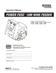
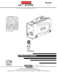
LF-72 WIRE FEEDER
For use with machines having Code Numbers:
March, 2010
11075, 11076, 11077
11209, 11210, 11211, 11227
11290, 11291, 11292, 11293
11606, 11607, 11608, 11609
11708, 11709, 11710, 11711
Safety Depends on You
Lincoln arc welding and cutting
equipment is designed and built
with safety in mind. However,
your overall safety can be
increased by proper installation ...
and thoughtful operation on your
part. DO NOT INSTALL, OPERATE OR REPAIR THIS EQUIPMENT WITHOUT READING
THIS MANUAL AND THE SAFETY PRECAUTIONS CONTAINED
THROUGHOUT. And, most
importantly, think before you act
and be careful.
IP21
IEC 60974-5
OPERATOR’S MANUAL
Copyright © Lincoln Global Inc.
• World's Leader in Welding and Cutting Products •
• Sales and Service through Subsidiaries and Distributors Worldwide •
Cleveland, Ohio 44117-1199 U.S.A. TEL: 1.888.935.3877 FAX: 216.486.1751 WEB SITE: www.lincolnelectric.com
i
i
SAFETY
WARNING
CALIFORNIA PROPOSITION 65 WARNINGS
Diesel engine exhaust and some of its constituents
are known to the State of California to cause cancer, birth defects, and other reproductive harm.
The Above For Diesel Engines
The engine exhaust from this product contains
chemicals known to the State of California to cause
cancer, birth defects, or other reproductive harm.
The Above For Gasoline Engines
ARC WELDING CAN BE HAZARDOUS. PROTECT YOURSELF AND OTHERS FROM POSSIBLE SERIOUS INJURY OR DEATH.
KEEP CHILDREN AWAY. PACEMAKER WEARERS SHOULD CONSULT WITH THEIR DOCTOR BEFORE OPERATING.
Read and understand the following safety highlights. For additional safety information, it is strongly recommended that you
purchase a copy of “Safety in Welding & Cutting - ANSI Standard Z49.1” from the American Welding Society, P.O. Box
351040, Miami, Florida 33135 or CSA Standard W117.2-1974. A Free copy of “Arc Welding Safety” booklet E205 is available
from the Lincoln Electric Company, 22801 St. Clair Avenue, Cleveland, Ohio 44117-1199.
BE SURE THAT ALL INSTALLATION, OPERATION, MAINTENANCE AND REPAIR PROCEDURES ARE
PERFORMED ONLY BY QUALIFIED INDIVIDUALS.
FOR ENGINE
powered equipment.
1.h. To avoid scalding, do not remove the
radiator pressure cap when the engine is
hot.
1.a. Turn the engine off before troubleshooting and maintenance
work unless the maintenance work requires it to be running.
____________________________________________________
1.b. Operate engines in open, well-ventilated
areas or vent the engine exhaust fumes
outdoors.
____________________________________________________
1.c. Do not add the fuel near an open flame
welding arc or when the engine is running.
Stop the engine and allow it to cool before
refueling to prevent spilled fuel from vaporizing on contact with hot engine parts and
igniting. Do not spill fuel when filling tank. If
fuel is spilled, wipe it up and do not start
engine until fumes have been eliminated.
____________________________________________________
1.d. Keep all equipment safety guards, covers and devices in
position and in good repair.Keep hands, hair, clothing and
tools away from V-belts, gears, fans and all other moving
parts when starting, operating or repairing equipment.
____________________________________________________
1.e. In some cases it may be necessary to remove safety
guards to perform required maintenance. Remove
guards only when necessary and replace them when the
maintenance requiring their removal is complete.
Always use the greatest care when working near moving
parts.
___________________________________________________
1.f. Do not put your hands near the engine fan.
Do not attempt to override the governor or
idler by pushing on the throttle control rods
while the engine is running.
ELECTRIC AND
MAGNETIC FIELDS
may be dangerous
2.a. Electric current flowing through any conductor causes
localized Electric and Magnetic Fields (EMF). Welding
current creates EMF fields around welding cables and
welding machines
2.b. EMF fields may interfere with some pacemakers, and
welders having a pacemaker should consult their physician
before welding.
2.c. Exposure to EMF fields in welding may have other health
effects which are now not known.
2.d. All welders should use the following procedures in order to
minimize exposure to EMF fields from the welding circuit:
2.d.1. Route the electrode and work cables together - Secure
them with tape when possible.
2.d.2. Never coil the electrode lead around your body.
2.d.3. Do not place your body between the electrode and
work cables. If the electrode cable is on your right
side, the work cable should also be on your right side.
2.d.4. Connect the work cable to the workpiece as close as
possible to the area being welded.
___________________________________________________
1.g. To prevent accidentally starting gasoline engines while
turning the engine or welding generator during maintenance
work, disconnect the spark plug wires, distributor cap or
magneto wire as appropriate.
2.d.5. Do not work next to welding power source.
ii
ii
SAFETY
ELECTRIC SHOCK can
kill.
3.a. The electrode and work (or ground) circuits
are electrically “hot” when the welder is on.
Do not touch these “hot” parts with your bare
skin or wet clothing. Wear dry, hole-free
gloves to insulate hands.
3.b. Insulate yourself from work and ground using dry insulation.
Make certain the insulation is large enough to cover your full
area of physical contact with work and ground.
In addition to the normal safety precautions, if welding
must be performed under electrically hazardous
conditions (in damp locations or while wearing wet
clothing; on metal structures such as floors, gratings or
scaffolds; when in cramped positions such as sitting,
kneeling or lying, if there is a high risk of unavoidable or
accidental contact with the workpiece or ground) use
the following equipment:
• Semiautomatic DC Constant Voltage (Wire) Welder.
• DC Manual (Stick) Welder.
• AC Welder with Reduced Voltage Control.
3.c. In semiautomatic or automatic wire welding, the electrode,
electrode reel, welding head, nozzle or semiautomatic
welding gun are also electrically “hot”.
3.d. Always be sure the work cable makes a good electrical
connection with the metal being welded. The connection
should be as close as possible to the area being welded.
3.e. Ground the work or metal to be welded to a good electrical
(earth) ground.
3.f. Maintain the electrode holder, work clamp, welding cable and
welding machine in good, safe operating condition. Replace
damaged insulation.
3.g. Never dip the electrode in water for cooling.
3.h. Never simultaneously touch electrically “hot” parts of
electrode holders connected to two welders because voltage
between the two can be the total of the open circuit voltage
of both welders.
3.i. When working above floor level, use a safety belt to protect
yourself from a fall should you get a shock.
ARC RAYS can burn.
4.a. Use a shield with the proper filter and cover
plates to protect your eyes from sparks and
the rays of the arc when welding or observing
open arc welding. Headshield and filter lens
should conform to ANSI Z87. I standards.
4.b. Use suitable clothing made from durable flame-resistant
material to protect your skin and that of your helpers from
the arc rays.
4.c. Protect other nearby personnel with suitable, non-flammable
screening and/or warn them not to watch the arc nor expose
themselves to the arc rays or to hot spatter or metal.
FUMES AND GASES
can be dangerous.
5.a. Welding may produce fumes and gases
hazardous to health. Avoid breathing these
fumes and gases. When welding, keep
your head out of the fume. Use enough
ventilation and/or exhaust at the arc to keep
fumes and gases away from the breathing zone. When
welding with electrodes which require special
ventilation such as stainless or hard facing (see
instructions on container or MSDS) or on lead or
cadmium plated steel and other metals or coatings
which produce highly toxic fumes, keep exposure as
low as possible and within applicable OSHA PEL and
ACGIH TLV limits using local exhaust or mechanical
ventilation. In confined spaces or in some circumstances, outdoors, a respirator may be required.
Additional precautions are also required when welding
on galvanized steel.
5. b. The operation of welding fume control equipment is affected
by various factors including proper use and positioning of
the equipment, maintenance of the equipment and the specific welding procedure and application involved. Worker
exposure level should be checked upon installation and
periodically thereafter to be certain it is within applicable
OSHA PEL and ACGIH TLV limits.
5.c. Do not weld in locations near chlorinated hydrocarbon vapors
coming from degreasing, cleaning or spraying operations.
The heat and rays of the arc can react with solvent vapors to
form phosgene, a highly toxic gas, and other irritating products.
3.j. Also see Items 6.c. and 8.
5.d. Shielding gases used for arc welding can displace air and
cause injury or death. Always use enough ventilation,
especially in confined areas, to insure breathing air is safe.
5.e. Read and understand the manufacturer’s instructions for this
equipment and the consumables to be used, including the
material safety data sheet (MSDS) and follow your
employer’s safety practices. MSDS forms are available from
your welding distributor or from the manufacturer.
5.f. Also see item 1.b.
Jan ‘09
iii
iii
SAFETY
WELDING and CUTTING
SPARKS can
cause fire or explosion.
6.a. Remove fire hazards from the welding area.
If this is not possible, cover them to prevent
the welding sparks from starting a fire.
Remember that welding sparks and hot
materials from welding can easily go through small cracks
and openings to adjacent areas. Avoid welding near
hydraulic lines. Have a fire extinguisher readily available.
6.b. Where compressed gases are to be used at the job site,
special precautions should be used to prevent hazardous
situations. Refer to “Safety in Welding and Cutting” (ANSI
Standard Z49.1) and the operating information for the
equipment being used.
6.c. When not welding, make certain no part of the electrode
circuit is touching the work or ground. Accidental contact
can cause overheating and create a fire hazard.
6.d. Do not heat, cut or weld tanks, drums or containers until the
proper steps have been taken to insure that such procedures
will not cause flammable or toxic vapors from substances
inside. They can cause an explosion even though they have
been “cleaned”. For information, purchase “Recommended
Safe Practices for the Preparation for Welding and Cutting of
Containers and Piping That Have Held Hazardous
Substances”, AWS F4.1 from the American Welding Society
(see address above).
6.e. Vent hollow castings or containers before heating, cutting or
welding. They may explode.
6.f. Sparks and spatter are thrown from the welding arc. Wear oil
free protective garments such as leather gloves, heavy shirt,
cuffless trousers, high shoes and a cap over your hair. Wear
ear plugs when welding out of position or in confined places.
Always wear safety glasses with side shields when in a
welding area.
6.g. Connect the work cable to the work as close to the welding
area as practical. Work cables connected to the building
framework or other locations away from the welding area
increase the possibility of the welding current passing
through lifting chains, crane cables or other alternate circuits. This can create fire hazards or overheat lifting chains
or cables until they fail.
6.h. Also see item 1.c.
CYLINDER may explode
if damaged.
7.a. Use only compressed gas cylinders
containing the correct shielding gas for the
process used and properly operating
regulators designed for the gas and
pressure used. All hoses, fittings, etc. should be suitable for
the application and maintained in good condition.
7.b. Always keep cylinders in an upright position securely
chained to an undercarriage or fixed support.
7.c. Cylinders should be located:
• Away from areas where they may be struck or subjected to
physical damage.
• A safe distance from arc welding or cutting operations and
any other source of heat, sparks, or flame.
7.d. Never allow the electrode, electrode holder or any other
electrically “hot” parts to touch a cylinder.
7.e. Keep your head and face away from the cylinder valve outlet
when opening the cylinder valve.
7.f. Valve protection caps should always be in place and hand
tight except when the cylinder is in use or connected for
use.
7.g. Read and follow the instructions on compressed gas
cylinders, associated equipment, and CGA publication P-l,
“Precautions for Safe Handling of Compressed Gases in
Cylinders,” available from the Compressed Gas Association
1235 Jefferson Davis Highway, Arlington, VA 22202.
FOR ELECTRICALLY
powered equipment.
8.a. Turn off input power using the disconnect
switch at the fuse box before working on
the equipment.
8.b. Install equipment in accordance with the U.S. National
Electrical Code, all local codes and the manufacturer’s
recommendations.
8.c. Ground the equipment in accordance with the U.S. National
Electrical Code and the manufacturer’s recommendations.
6.I. Read and follow NFPA 51B “ Standard for Fire Prevention
During Welding, Cutting and Other Hot Work”, available
from NFPA, 1 Batterymarch Park, PO box 9101, Quincy, Ma
022690-9101.
6.j. Do not use a welding power source for pipe thawing.
Refer to http://www.lincolnelectric.com/safety for additional safety information.
Jan ‘09
iv
iv
SAFETY
PRÉCAUTIONS DE SÛRETÉ
Pour votre propre protection lire et observer toutes les instructions
et les précautions de sûreté specifiques qui parraissent dans ce
manuel aussi bien que les précautions de sûreté générales suivantes:
Sûreté Pour Soudage A L’Arc
1. Protegez-vous contre la secousse électrique:
a. Les circuits à l’électrode et à la piéce sont sous tension
quand la machine à souder est en marche. Eviter toujours
tout contact entre les parties sous tension et la peau nue
ou les vétements mouillés. Porter des gants secs et sans
trous pour isoler les mains.
b. Faire trés attention de bien s’isoler de la masse quand on
soude dans des endroits humides, ou sur un plancher
metallique ou des grilles metalliques, principalement dans
les positions assis ou couché pour lesquelles une grande
partie du corps peut être en contact avec la masse.
c. Maintenir le porte-électrode, la pince de masse, le câble
de soudage et la machine à souder en bon et sûr état
defonctionnement.
d.Ne jamais plonger le porte-électrode dans l’eau pour le
refroidir.
e. Ne jamais toucher simultanément les parties sous tension
des porte-électrodes connectés à deux machines à souder
parce que la tension entre les deux pinces peut être le
total de la tension à vide des deux machines.
f. Si on utilise la machine à souder comme une source de
courant pour soudage semi-automatique, ces precautions
pour le porte-électrode s’applicuent aussi au pistolet de
soudage.
2. Dans le cas de travail au dessus du niveau du sol, se protéger
contre les chutes dans le cas ou on recoit un choc. Ne jamais
enrouler le câble-électrode autour de n’importe quelle partie
du corps.
3. Un coup d’arc peut être plus sévère qu’un coup de soliel,
donc:
a. Utiliser un bon masque avec un verre filtrant approprié
ainsi qu’un verre blanc afin de se protéger les yeux du rayonnement de l’arc et des projections quand on soude ou
quand on regarde l’arc.
b. Porter des vêtements convenables afin de protéger la
peau de soudeur et des aides contre le rayonnement de
l‘arc.
c. Protéger l’autre personnel travaillant à proximité au
soudage à l’aide d’écrans appropriés et non-inflammables.
4. Des gouttes de laitier en fusion sont émises de l’arc de
soudage. Se protéger avec des vêtements de protection libres
de l’huile, tels que les gants en cuir, chemise épaisse, pantalons sans revers, et chaussures montantes.
5. Toujours porter des lunettes de sécurité dans la zone de
soudage. Utiliser des lunettes avec écrans lateraux dans les
zones où l’on pique le laitier.
6. Eloigner les matériaux inflammables ou les recouvrir afin de
prévenir tout risque d’incendie dû aux étincelles.
7. Quand on ne soude pas, poser la pince à une endroit isolé de
la masse. Un court-circuit accidental peut provoquer un
échauffement et un risque d’incendie.
8. S’assurer que la masse est connectée le plus prés possible
de la zone de travail qu’il est pratique de le faire. Si on place
la masse sur la charpente de la construction ou d’autres
endroits éloignés de la zone de travail, on augmente le risque
de voir passer le courant de soudage par les chaines de levage, câbles de grue, ou autres circuits. Cela peut provoquer
des risques d’incendie ou d’echauffement des chaines et des
câbles jusqu’à ce qu’ils se rompent.
9. Assurer une ventilation suffisante dans la zone de soudage.
Ceci est particuliérement important pour le soudage de tôles
galvanisées plombées, ou cadmiées ou tout autre métal qui
produit des fumeés toxiques.
10. Ne pas souder en présence de vapeurs de chlore provenant
d’opérations de dégraissage, nettoyage ou pistolage. La
chaleur ou les rayons de l’arc peuvent réagir avec les vapeurs
du solvant pour produire du phosgéne (gas fortement toxique)
ou autres produits irritants.
11. Pour obtenir de plus amples renseignements sur la sûreté,
voir le code “Code for safety in welding and cutting” CSA
Standard W 117.2-1974.
PRÉCAUTIONS DE SÛRETÉ POUR
LES MACHINES À SOUDER À
TRANSFORMATEUR ET À
REDRESSEUR
1. Relier à la terre le chassis du poste conformement au code de
l’électricité et aux recommendations du fabricant. Le dispositif
de montage ou la piece à souder doit être branché à une
bonne mise à la terre.
2. Autant que possible, I’installation et l’entretien du poste seront
effectués par un électricien qualifié.
3. Avant de faires des travaux à l’interieur de poste, la debrancher à l’interrupteur à la boite de fusibles.
4. Garder tous les couvercles et dispositifs de sûreté à leur
place.
Mar. ‘93
v
TABLE OF CONTENTS
Thank You
v
for selecting a QUALITY product by Lincoln Electric. We want you
to take pride in operating this Lincoln Electric Company product
••• as much pride as we have in bringing this product to you!
CUSTOMER ASSISTANCE POLICY
The business of The Lincoln Electric Company is manufacturing and selling high quality welding equipment, consumables, and cutting equipment. Our challenge is to meet the needs of our customers and to exceed their expectations. On occasion, purchasers may ask Lincoln
Electric for advice or information about their use of our products. We respond to our customers based on the best information in our possession at that time. Lincoln Electric is not in a position to warrant or guarantee such advice, and assumes no liability, with respect to such information or advice. We expressly disclaim any warranty of any kind, including any warranty of fitness for any customer’s particular purpose,
with respect to such information or advice. As a matter of practical consideration, we also cannot assume any responsibility for updating or
correcting any such information or advice once it has been given, nor does the provision of information or advice create, expand or alter any
warranty with respect to the sale of our products.
Lincoln Electric is a responsive manufacturer, but the selection and use of specific products sold by Lincoln Electric is solely within the control
of, and remains the sole responsibility of the customer. Many variables beyond the control of Lincoln Electric affect the results obtained in
applying these types of fabrication methods and service requirements.
Subject to Change – This information is accurate to the best of our knowledge at the time of printing. Please refer to www.lincolnelectric.com
for any updated information.
Please Examine Carton and Equipment For Damage Immediately
When this equipment is shipped, title passes to the purchaser upon receipt by the carrier. Consequently, Claims
for material damaged in shipment must be made by the purchaser against the transportation company at the
time the shipment is received.
Please record your equipment identification information below for future reference. This information can be
found on your machine nameplate.
Product _________________________________________________________________________________
Model Number ___________________________________________________________________________
Code Number or Date Code_________________________________________________________________
Serial Number____________________________________________________________________________
Date Purchased___________________________________________________________________________
Where Purchased_________________________________________________________________________
Whenever you request replacement parts or information on this equipment, always supply the information you
have recorded above. The code number is especially important when identifying the correct replacement parts.
On-Line Product Registration
- Register your machine with Lincoln Electric either via fax or over the Internet.
• For faxing: Complete the form on the back of the warranty statement included in the literature packet
accompanying this machine and fax the form per the instructions printed on it.
• For On-Line Registration: Go to our WEB SITE at www.lincolnelectric.com. Choose “Quick Links” and then
“Product Registration”. Please complete the form and submit your registration.
Read this Operators Manual completely before attempting to use this equipment. Save this manual and keep it
handy for quick reference. Pay particular attention to the safety instructions we have provided for your protection.
The level of seriousness to be applied to each is explained below:
WARNING
This statement appears where the information must be followed exactly to avoid serious personal injury or loss of life.
CAUTION
This statement appears where the information must be followed to avoid minor personal injury or damage to this equipment.
vi
vi
TABLE OF CONTENTS
Page
Installation ............................................................................................................Section A
Technical Specifications ...............................................................................................A-1
Safety Precautions........................................................................................................A-2
Location ...................................................................................................................A-2
Mounting...................................................................................................................A-2
Bench Mount ............................................................................................................A-3
Swivel Mount ............................................................................................................A-3
Boom Mount .............................................................................................................A-3
Suspended ...............................................................................................................A-3
Weld Cable Sizes .....................................................................................................A-4
Coaxial Weld Cables ................................................................................................A-5
Weld Cable Connections..........................................................................................A-5
Analog Control Cable Connections ...............................................................................A-6
Analog Miller Control Cable Adapter ............................................................................A-7
Welding Gun/Wire Feeder Trigger Connector .........................................................A-8
High Frequency Protection ......................................................................................A-8
Remote Sense Lead Specifications.........................................................................A-8
Wire Drive Systems ......................................................................................................A-8
Welding Guns, Torches and Accessories.....................................................................A-9
Procedure for Changing Drive and Idle Roll Sets .......................................................A-10
Wire Drive Configuration ..............................................................................A-10, A-11
Pressure Arm Adjustment......................................................................................A-11
Wire Reel Loading .................................................................................................A-12
Weld Wire Routing.................................................................................................A-13
Shielding Gas Connections ........................................................................................A-14
Installing Electrode Conduit Kits .................................................................................A-15
Aluminum Wire Preparations ......................................................................................A-16
Base Model, Bench Model Standard Duty and Bench Model Heavy Duty .................A-17
Typical System Configurations ...................................................................................A-18
__________________________________________________________________________
Operation ..............................................................................................................Section B
Safety Precautions........................................................................................................B-1
Graphic Symbols...........................................................................................................B-1
Common Welding Abbreviations...................................................................................B-2
Product Description.......................................................................................................B-2
Recommended Processes and Required Equipment ...................................................B-2
Front Panel Controls and Connections .........................................................................B-3
1. Remote Voltage Control Kit (Optional).................................................................B-4
2. Burnback and Postflow Timer Kit (Optional) ........................................................B-4
3. Thermal LED, Motor Overload .............................................................................B-4
4. Cold Feed/Gas Purge Switch...............................................................................B-4
5. 2 Step - Trigger Interlock Switch ..................................................................B-4, B-5
6. Wire Feed Speed Knob........................................................................................B-5
7. Gun Receiver Bushing .........................................................................................B-5
8. Trigger Connector 5-Pin Amphenol .....................................................................B-5
__________________________________________________________________________
Accessories ..........................................................................................................Section C
General Options and Accessories ..................................................................C-1 Thru C4
___________________________________________________________________________________
vii
vii
TABLE OF CONTENTS
Page
Maintenance ....................................................................................................Section D
Safety Precautions ................................................................................................D-1
Routine Maintenance.............................................................................................D-1
Periodic Maintenance ............................................................................................D-1
Calibration Specification ........................................................................................D-1
Major Component Locations..................................................................................D-2
________________________________________________________________________
Troubleshooting ..............................................................................................Section E
Safety Precautions.................................................................................................E-1
How To Use Troubleshooting Guide......................................................................E-1
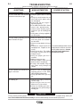
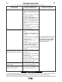
Troubleshooting Guides .................................................................................E-2, E-3
________________________________________________________________________
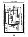
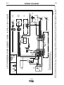
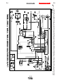
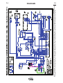
Wiring Diagram and Dimension Prints ..........................................................Section F
________________________________________________________________________
Parts Lists.............................................................................................P-501 and P-622
________________________________________________________________________
LF-72
A-1
A-1
INSTALLATION
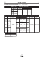
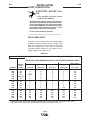
TECHNICAL SPECIFICATIONS: LF-72 Wire Feeder
SPEC.#
TYPE
WIRE FEED SPEED RANGE
Wire Size
LF-72
K2327-1
K2327-4
K2327-2
K2327-5
K2327-3
K2327-6
K2327-7
SPEC.#
TYPE
LF-72
K2327-4
Base Model
Solid
Cored
50-800 IPM
(1.27-20.3 m/m)
.023 - 1/16 in.
(0.6 - 1.6 mm)
.035 - 5/64 in
(0.9 - 2.0 mm)
Base Model
Bench Model
Standard Duty
Bench Model
Heavy Duty
CONTROL BOX, WIRE DRIVE AND COMPLETE UNITS
INPUT POWER
PHYSICAL SIZE•
TEMPERATURE RATING
Input Voltage
and Current
K2327-1
Speed
Height
11.1“
( 282 mm)
Dimensions
Width
Depth
10.2“
(259 mm)
12.9“
(328 mm)
Weight
43 Lbs
(19.7 Kg.)
Operating
Storage
26.5 Lbs
(12.0 Kg)
Height
Dimensions
Width
Depth
Weight
LF-72
K2327-2
K2327-5
Bench
Standard
Duty
24-42VAC
9 AMPS
12.6“
( 320 mm)
Height
K2327-3
K2327-6
K2327-7
10.9“
(277 mm)
Dimensions
Width
22.5“
(572 mm)
Depth
52.5 Lbs
(23.8 Kg.)
Weight
LF-72
Bench
Heavy
Duty
15.3“
( 389 mm)
13.0“
(330 mm)
WELDING CAPACITY RATING
Amp Rating
Duty Cycle
500 A
60%
Dimensions do not include wire reel.
LF-72
27.7“
(704 mm)
67.5 Lbs
(30.6 Kg.)
14°F to 104°F
(-10°C to 40°C)
-40°F to 185°F
(-40°C to 85°C)
A-2
A-2
INSTALLATION
SAFETY PRECAUTION
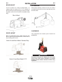
MOUNTING
ELECTRIC SHOCK can kill.
• Only qualified personnel should
perform this installation.
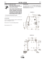
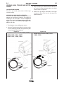
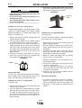
For location and size, LF-72 Bench Model Rear
Mounting Holes (See Figure A.1) and for Bottom
Mounting Holes (See Figure A.2).
• Turn off the input power to the
power source at the disconnect
switch or fuse box before working
on this equipment. Turn off the
input power to any other equipment
connected to the welding system at
the disconnect switch or fuse box
before working on this equipment.
FIGURE A.1
• Do not touch electrically hot parts.
----------------------------------------------------------------------------------------
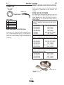
LOCATION
The LF-72 may be placed on a bench or mounted on
top of a welding power source.
Place the LF-72 in a clean and dry location.
Do not stack the LF-72.
FIGURE A.2
LF-72
A-3
A-3
INSTALLATION
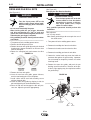
BENCH MOUNT
BOOM MOUNT
The LF-72 mounts in a variety of configurations. As
shipped from the factory, the LF-72 is suitable for
bench mounting or placing directly on top of the welding power source (CV-xxx and DC-xxx product family
only).
When boom mounting, remove the wire reel stand (if
assembled) and secure the wire feeder directly to the
desired surface.
Bench Mount
SUSPENDED
SWIVEL MOUNT
Both the standard duty bench model and heavy duty
bench model may be mounted onto a swivel when a
top a welding power source.
Only suspend the wire feeder by the lift bail of the
portability kit.
Swivel Kit and Bench Model, Standard Duty
WARNING
Swivel Kit and Base Model LF-72
Alternative methods for hanging the wire feeder
must not be used unless insulation is provided
between the wire feeder enclosure and the hanging device.
------------------------------------------------------------------------
LF-72
A-4
A-4
INSTALLATION
SAFETY PRECAUTION
ELECTRIC SHOCK can
kill.
• Only qualified personnel should
perform this installation.
• Turn off the input power to the power source at
the disconnect switch or fuse box before working on this equipment. Turn off the input power
to any other equipment connected to the welding system at the disconnect switch or fuse
box before working on this equipment.
• Do not touch electrically hot parts.
----------------------------------------------------------------------
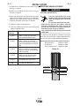
WELD CABLE SIZES
Table A.1 has the copper cable sizes recommended
for different currents and duty cycles. Lengths stipulated are the distance from the welder to work and
back to the welder again. Cable sizes are increased
for greater lengths primarily for the purpose of minimizing voltage in the welding circuit.
TABLE A.1
RECOMMENDED CABLE SIZES (RUBBER COVERED COPPER - RATED 75°C)**
CABLE SIZES FOR COMBINED LENGTHS OF ELECTRODE AND WORK CABLES
0 to 50 Ft.
50 to 100Ft.
100 to 150 Ft.
150 to 200 Ft.
200 to 250 Ft.
Amperes
Percent
Duty
Cycle
0 to 15 m
15 to 31 m
31 to 48 m
48 to 61 m
61 to 76 m
200
200
225
225
250
60
100
20
40 & 30
30
2
2
4 or 5
3
3
2
2
3
3
3
2
2
2
2
2
1
1
1
1
1
1/0
1/0
1/0
1/0
1/0
250
250
250
300
40
60
100
60
2
1
1
1
2
1
1
1
1
1
1
1
1
1
1
1/0
1/0
1/0
1/0
2/0
325
350
400
400
500
100
60
60
100
60
2/0
1/0
2/0
3/0
2/0
2/0
1/0
2/0
3/0
2/0
2/0
2/0
2/0
3/0
3/0
2/0
2/0
3/0
3/0
3/0
3/0
3/0
4/0
4/0
4/0
** Tabled values are for operation at ambient temperatures of 40°C and below. Applications above 40°C
may require cables larger than recommended, or cables rated higher than 75°C.
LF-72
A-5
A-5
INSTALLATION
COAXIAL WELD CABLES
Coaxial welding cables are specially designed welding
cables for pulse welding or STT welding. Coaxial weld
cables feature low inductance, allowing fast changes
in the weld current. Regular cables have a higher
inductance which may distort the pulse or STT wave
shape. Inductance becomes more severe as the weld
cables become longer.
Coaxial weld cables are recommended for all pulse
and STT welding, especially when the total weld cable
length (electrode cable + work cable) exceeds 50 feet
(7.6m)
A coaxial weld cable is constructed by 8 small leads
wrapped around one large lead. The large inner lead
connects to the electrode stud on the power source
and the electrode connection on the wire feeder. The
small leads combine together to form the work lead,
one end attached to the power source and the other
end to the work piece. (See Coaxial weld Cable below.)
WELD CABLE CONNECTION
Connect a work lead of sufficient size between the
proper output stud on the power source and the work.
Be sure the connection to the work makes tight metal
to metal electrical contact. Poor work lead connections can result in poor welding performance.
Work
Electrode
Work
Power Source
Work
Electrode
Coaxial Weld Cable
Wire Feeder
Electrode
Work
LF-72
A-6
A-6
INSTALLATION
ANALOG CONTROL CABLE
CONTROL CABLE CONNECTIONS
• All control cables can be connected end to end to
extend their length.
The control cable connecting the wire feeder to the
power source is specially made for the welding environment.
The wire feeder power requires overcurrent protection. Connect the wire feeder only to power sources
with overcurrent protection of no more than 15 amps.
POWER SOURCE
I
J
H N
G
F
PIN
A
B
C
D
E
F
G
H
I
J
WIRE FEEDER
A
K B
L C
M
D
E
B
A
C L
D
E
FUNCTION
J
K I
N H
M G
F
LEAD#
Unused
------Reserved
------Welding Output Control
2
(trigger from feeder)
Welding Output Control
4
(trigger from feeder)
Remote Voltage Control
77
(“+” supply from feeder or remote)
Remote Voltage Control
76
(control signal from feeder or remote)
Remote Voltage Control
75
(“-” supply from feeder or remote)
Reserved
42 VAC
41
Reserve for Future Use.
K
L
42 VAC
Reserve for Future Use.
M
N
Unused
Electrode voltage from feeder
42
------67
Do not use more than 100 ft (30.5 m) of control cable
between the wire feeder and power source.
LF-72
A-7
A-7
INSTALLATION
ANALOG MILLER CONTROL CABLE
ADAPTER K2335-1
This Lincoln Electric wire feeder may be mounted to a limited number of Miller Electric power sources. The Miller
power source must have the amphenol pin definition shown
in the table below for proper operation of the wire feeder.
Operation of Lincoln wire feeders on Miller power sources
may result in lack of high speeds or reduce pull force on
high wire feed speeds. Maximum wire feed speed for the
LF-72 operating on a Miller power source is approximately
720ipm. Be sure the Miller power source provides 24 VAC
to the wire feeder and has overcurrent protection of no more
than 15 amps. The power source must not exceed 113VDC
peak.
POWER SOURCE
H
I
G
J
N
F
K
M
A
L
E
B
D
WIRE FEEDER
C
C
D
A
L
E
K
J
N
I
M G
F
H
LINCOLN WIRE FEEDER
MILLER POWER SOURCE
Pin
B
Pin
Function
Function
A
24 VAC to feeder
B
C
Welding Output Control
+10VDC to feeder for remote control
I
D
C
E
D
Remote control common
G
E
0-10VDC from feeder for remote control.
F
F
Current feedback to feeder.
Scaled 0-10V. 1 V = 100 amps.
Referenced to pin D.
24 VAC common.
Arc Voltage feedback to feeder.
Scaled 0-10V. 1 V = 10 Arc volts.
Referenced to pin D.
J
42 VAC feeder
Welding Output Control
Welding Output Control
Remote Voltage Control ("+" supply, from
power source)
Remote Voltage Control ("-" supply, from
power source)
Remote Voltage Control (control signal from
feeder or remote.)
Reserved for future use.
K
L
42 VAC to feeder
Reserved for future use.
N
Electrode voltage to power source (67)
G
H
I
J
K
L
M
N
Miller is a registered trademark not owned or licensed by The Lincoln Electric Company.
LF-72
A-8
WELDING GUN/WIRE FEEDER TRIGGER
CONNECTOR
Wire Feeder
Amphenol
A
B
A-8
INSTALLATION
D
C
Refer to the power source instruction manual for
instructions for connecting the wire feeder for STT
welding.
Welding G un
E
REMOTE SENSE LEAD SPECIFICATIONS
WIRE DRIVE SYSTEMS
Trigger Lead
Drive Roll Kits are designed to feed specific types and
wire sizes. The LF-72 Bench Model comes with the
combo KP1696-1. All other Drive Roll Kits listed are
not included, but are available for ordering from the
following tables:
Drive Roll Kits, Steel Wires
Includes: 2 Smooth V groove drive rolls and an inner
wire guide.
Wire Feeder
Pin
Function
A
Gun Trigger
B
C
Common
D
E
-
KP1696-030S
KP1696-035S
KP1696-045S
KP1696-052S
KP1696-1/16S
KP1696-1
KP1696-2
HIGH FREQUENCY PROTECTION
Locate the LF-72 away from radio controlled machinery. The normal operation of the LF-72 may adversely affect the operation of RF controlled equipment,
which may result in bodily injury or damage to the
equipment
.023-.030 (0.6-0.8mm)
.035 (0.9mm)
.045 (1.2mm)
.052 (1.4mm)
1/16 (1.6mm)
.035, .O45 (0.9, 1.2mm)
.040 (1.0mm)
Drive Roll Kits, Cored Wires
Includes: 2 Knurled drive rolls and an inner wire guide.
KP1697-035C
KP1697-045C
KP1697-052C
KP1697-1/16C
KP1697-068
KP1697-5/64C
.030-.035" (0.8-0.9mm)
.040-.045" (1.0-1.2mm)
.052" (1.4mm)
1/16" (1.6mm)
.068-.072" (1.7-1.8mm)
5/64" (2.0mm)
Drive Roll Kits, Aluminum Wire
Includes: 2 polished U groove drive rolls, outer wire
guide and an inner wire guide.
KP1695-035A
KP1695-040A
KP1695-3/64A
KP1695-1/16A
.035" (0.9 mm)
.040" (1.0mm)
3/64" (1.2mm)
1/16" (1.6mm)
DRIVE ROLLS
INNER WIRE
GUIDE
LF-72
A-9
A-9
INSTALLATION
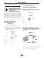
WELDING GUNS, TORCHES AND ACCESSORIES
GUN RECEIVER BUSHING
The LF-72 wire feeder comes with a K1500-2 gun
receiver bushing.
MAGNUM GUN AND CABLE ASSEMBLIES
The LF-72 wire feeder model will accept a number of
optional gun and cable assemblies. An example of
installing the Gun and Cable is shown in Figure A.3
with a 15 ft. (4.6m) long Magnum 400 gun and cable.
Figure A.3a with a 15 ft. (4.6m) long Magnum Pro
350 gun and cable.
3. Fully insert the gun cable connector end into the
gun receiver bushing and gently tighten the thumb
screw as show in Figure A.5.
4. Connect the gun trigger connector to the trigger
receptacle. Make sure that the key ways are
aligned and insert.
1. Turn off power at the welding power source.
2. Unscrew Thumb screw on Wire Drive Unit, until tip
of screw no longer protrudes into gun bushing hole
as seen from the front of machine.
Figure A.3
FIGURE A.3 for Codes 11075,
11076, 11077,
11209, 11210, 11211, 11227
11290, 11291, 11292, 11293
Figure A.3a
FIGURE A.3a for Codes 11606,
11608, 11609
LF-72
LF-72
LF-72
11607,
A-10
A-10
INSTALLATION
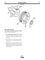
PROCEDURE FOR CHANGING
DRIVE AND IDLE ROLL SETS
WIRE DRIVE CONFIGURATION
(See Figure A.5)
Changing the Gun Receiver Bushing
(See Figure A.4 )
WARNING
WARNING
ELECTRIC SHOCK can kill.
• Turn the input power OFF at the
welding power source before installation or changing drive rolls and/or
guides.
• Do not touch electrically live parts.
• When inching with the gun trigger, electrode
and drive mechanism are "hot" to work and
ground and could remain energized several seconds after the gun trigger is released.
• Only qualified personnel should perform maintenance work.
-----------------------------------------------------------------------1. Turn power off at the welding power source.
2. Release the idle roll pressure arm.
3. Remove the outer wire guide by turning the knurled
thumbscrews counter-clockwise to unscrew them
from the feed plate.
4. Rotate the triangular lock and remove the drive
rolls.
FIGURE A.4
ELECTRIC SHOCK can kill.
• Turn the input power OFF at the disconnect switch or fuse box before
attempting to connect or disconnect input power lines, output
cables or control cables.
• Only qualified personnel should perform this
installation.
-----------------------------------------------------------------------Tools required:
• 1/4" hex key wrench
Note: Some gun bushings do not require the use of
the thumb screw.
1. Turn power off at the welding power source.
2. Remove the welding wire from the wire drive.
3. Remove the thumb screw from the wire drive.
4. Remove the welding gun from the wire drive.
5. Loosen the socket head cap screw that holds the
connector bar against the gun bushing. Important:
Do not attempt to completely remove the socket
head cap screw.
6. Remove the outer wire guide, and push the gun
bushing out of the wire drive. Because of the precision fit, light tapping may be required to remove
the gun bushing.
5. Remove the inner wire guide.
6. Insert the new inner wire guide, groove side out,
over the two locating pins in the feed plate.
7. Install a drive roll on each hub assembly secure
with the triangular lock.
8. Install the outer wire guide by aligning it with the
pins and tightening the knurled thumbscrews.
9. Close the idle arm and engage the idle roll pressure arm. Adjust the pressure appropriately.
FIGURE A.5
THUMB SCREW
GUN RECEIVER BUSHING
OUTER WIRE GUIDE
CONNECTOR BLOCK
SOCKET HEAD
CAP SCREW
LOOSEN
LF-72
TIGHTEN
A-11
A-11
INSTALLATION
7. Disconnect the shielding gas hose from the gun
bushing, if required.
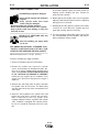
PRESSURE ARM ADJUSTMENT
WARNING
8. Connect the shielding gas hose to the new gun
bushing, if required.
9. Rotate the gun bushing until the thumb screw hole
aligns with the thumb screw hole in the feed plate.
Slide the gun receiver bushing into the wire drive
and verify the thumb screw holes are aligned.
ELECTRIC SHOCK can kill.
Gun Receiver
Bushing
For use With
K1500-1
K466-1 Lincoln gun connectors;
Innershield and Subarc guns)
• Turn the input power OFF at the
welding power source before installation or changing drive rolls and/or
guides.
• Do not touch electrically live parts.
• When inching with the gun trigger, electrode
and drive mechanism are "hot" to work and
ground and could remain energized several seconds after the gun trigger is released.
• Only qualified personnel should perform maintenance work.
-----------------------------------------------------------------------The pressure arm controls the amount of force the
drive rolls exert on the wire. Proper adjustment of the
pressure arm gives the best welding performance.
K1500-2
K466-2, K466-10 Lincoln gun
connectors; Magnum 200/300/400
guns and compatible with Tweco®
#4)
Set the pressure arm as follows (See Figure A.6):
Aluminum wires
between 1 and 3
Cored wires
between 3 and 4
Steel, Stainless wires between 4 and 6
K1500-3
K1637-7 Lincoln gun connectors;
Magnum 550 guns and compatible
with Tweco® #5)
K1500-4
K466-3 Lincoln gun connectors;
compatible with Miller® guns.)
K1500-5
(Compatible with Oxo® guns.)
K489-7
( Lincoln Fast-Mate guns.)
10. Tighten the socket head cap screw.
11. Insert the welding gun into the gun bushing and
tighten the thumb screw.
FIGURE A.6
CORED WIRES
OUTERSHIELD
METALSHIELD
INNERS HIELD
LF-72
12
34
56
SOLID WIRES
ALUMINUM
STEEL
STAINLE SS
A-12
INSTALLATION
WIRE REEL LOADING
A-12
3. Re-install the retaining collar. Make sure that the
release bar snaps out and that the retaining collar
fully engages the groove on the spindle.
FIGURE A.8
WARNING
• Keep hands, hair, clothing and tools away from
rotating equipment.
• Do not wear gloves when threading wire or
changing wire spool.
• Only qualified personnel should install, use or
service this equipment.
-----------------------------------------------------------------------
Retaining
Collar
Loading 10 to 15 lb. (4.5 – 6.8kg) Spools
A K468 spindle adapter is required for loading 2" wide
spools on 2" (51mm) spindles. Use a K468-1 spindle
adapter for loading 2-1/2" (64mm) wide spools. (See
figure A.7 and figure A.8)
1. Squeeze the release bar on the retaining collar and
remove it from the spindle.
2. Place the spindle adapter on the spindle, aligning
the spindle brake pin with the hole in the adapter.
3. Place the spool on the spindle and align the
adapter brake tab with one of the holes in the back
side of the spool. An indicator mark on the end of
the spindle shows the orientation of the brake tab.
Be certain the wire feeds off of the spool in the
proper direction.
4. Re-install the retaining collar. Make sure that the
release bar snaps out and that the retaining collar
fully engages the groove on the spindle.
FIGURE A.7
Adapter
Spindle Placement
The wire reel stand provides two mounting locations
for the spindle. Each mounting location consists of a
tube in the center of the mast and locating slots.
Loading 16 to 44 lb. (7.3 – 20kg) Spools
(See figure A.8)
1. Squeeze the release bar on the retaining collar and
remove it from the spindle.
2. Place the spool on the spindle, aligning the spindle
brake pin with one of the holes in the back side of
the spool. An indicator mark on the end of the spindle shows the orientation of the brake holding pin.
Be certain the wire feeds off of the spool in the
proper direction.
Loading 30 lb. (13.6 kg) Readi-Reels
(See Figure A.9)
A K363-P Readi-Reel adapter is required for loading
these spools on 2" (51mm) spindles.
1. Squeeze the release bar on the retaining collar and
remove it from the spindle.
2. Place the Readi-Reel adapter on the spindle, aligning the spindle brake pin with one of the holes in
the adapter.
3. Re-install the retaining collar. Make sure that the
release bar snaps out and that the retaining collar
fully engages the groove on the spindle.
4. Rotate the spindle and adapter until the retaining
spring is at the 12 o’clock position.
5. Position the Readi-Reel so that electrode de-reels
in the proper direction.
6. Set one of the Readi-Reel inside cage wires on the
slot in the retaining spring.
7. Lower the Read-Reel to depress the retaining
spring and align the other inside cage wires with
the grooves in the adapter.
8. Slide the cage all way onto the adapter until the
retaining spring "pops up" fully.
Removing a Readi-Reel
1. To remove a Readi-Reel from the an adapter,
depress the retaining spring with a thumb while
pulling the Readi-Reel cage from the adapter with
both hands. Do not remove the adapter from the
spindle.
LF-72
A-13
INSTALLATION
FIGURE A.9
WELD WIRE ROUTING
The electrode supply may be either from reels, ReadiReels, spools, or bulk packaged drums or reels.
Observe the following precautions:
a) The electrode must be routed to the wire drive
unit so that the bends in the wire are at a minimum, and also that the force required to pull the
wire from the reel into the wire drive unit is kept at
a minimum.
b) The electrode is “hot” when the gun trigger is
pressed and must be insulated from the boom
and structure.
c) If more than one wire feed unit shares the same
boom and are not sharing the some power source
output stud, their wire and reels must be insulated
from each other as well as insulated from their
mounting structure.
LF-72
A-13
A-14
INSTALLATION
A-14
5. Attach one end of the inlet hose to the outlet fitting
of the flow regulator. Attach the other end to the
welding system shielding gas inlet. Tighten the
union nuts with a wrench.
SHIELDING GAS CONNECTION
CYLINDER may explode if damaged.
• Keep cylinder upright and chained to
support.
• Keep cylinder away from areas
where it may be damaged.
• Never lift welder with cylinder attached.
• Never allow welding electrode to touch cylinder.
• Keep cylinder away from welding or other live
electrical circuits.
-----------------------------------------------------------------------BUILD-UP OF SHIELDING GAS may
harm health or kill.
6. Before opening the cylinder valve, turn the regulator
adjusting knob counterclockwise until the adjusting
spring pressure is released.
7. Standing to one side, open the cylinder valve slowly
a fraction of a turn. When the cylinder pressure
gage stops moving, open the valve fully.
8. The flow regulator is adjustable. Adjust it to the flow
rate recommended for the procedure and process
being used before making a weld.
• Shut off shielding gas supply when
not in use.
SEE AMERICAN NATIONAL STANDARD Z-49.1,
"SAFETY IN WELDING AND CUTTING" PUBLISHED BY THE AMERICAN WELDING SOCIETY.
-----------------------------------------------------------------------Maximum inlet pressure is 100 psi. (6.9 bar.)
Install the shielding gas supply as follows:
1. Secure the cylinder to prevent it from falling.
2. Remove the cylinder cap. Inspect the cylinder
valves and regulator for damaged threads, dirt,
dust, oil or grease. Remove dust and dirt with a
clean cloth. DO NOT ATTACH THE REGULATOR
IF OIL, GREASE OR DAMAGE IS PRESENT!
Inform your gas supplier of this condition. Oil or
grease in the presence of high pressure oxygen is
explosive.
3. Stand to one side away from the outlet and open
the cylinder valve for an instant. This blows away
any dust or dirt which may have accumulated in the
valve outlet.
4. Attach the flow regulator to the cylinder valve and
tighten the union nut(s) securely with a wrench.
Note: If connecting to 100% CO2 cylinder, insert
regulator adapter between regulator and cylinder
valve. If adapter is equipped with a plastic washer,
be sure it is seated for connection to the CO2 cylinder.
LF-72
A-15
A-15
INSTALLATION
(For Codes 11209, 11210, 11211 and above)
To install Lincoln conduit: (See Figure A.10b)
INSTALLING ELECTRODE
CONDUIT KITS
1. Turn off power at the welding power source.
WARNING
2. Remove the “O” ring holding the ball bushing
assembly to the back of the wire feeder. Remove
the ball bushing assembly.
ELECTRIC SHOCK can kill.
• Turn the input power OFF at the disconnect switch before working on
this equipment.
• Do not touch electrically hot parts.
-----------------------------------------------------------------------Electrode conduit is used when feeding wire drums,
from boxes or large reels. For best feeding results,
use the shortest conduit length possible and avoid
sharp bends.
FIGURE A.10b
"O" RING
(For Codes 11075, 11076, 11077)
Tools required: (See Figure A.10a)
• Snap Ring Pliers
To install Lincoln conduit:
1. Turn off power at the welding power source.
2. Remove the snap ring holding the ball bushing
assembly to the back of the wire feeder. Remove
the ball bushing assembly.
3. Place a K1546-xx conduit connector into the back
of the wire drive. Rotate the conduit connector to a
position where the thumb screw does not interfere
with the idle arm or door.
4. Tighten the set screw to secure the conduit connector in the wire drive.
FIGURE A.10a
5. Insert conduit through the sheet metal of the LF-72
and into the conduit connector. Secure with the
thumb screw.
FIGURE A.11
LF-72
A-16
A-16
INSTALLATION
ALUMINUM WIRE PREPARATIONS
(For Codes 11209, 11210, 11211 and above)
Tools required: (See Figure A.12b)
• 9/64" Hex key wrench
WARNING
ELECTRIC SHOCK can kill.
• Turn the input power OFF at the disconnect switch before working on
this equipment.
• Do not touch electrically hot parts.
1. Turn off power at the welding power source.
2. Remove the snap ring holding the ball bushing
assembly to the back of the wire feeder. Remove
the ball bushing assembly.
FIGURE A.12b
-----------------------------------------------------------------------Welding with aluminum filler wires requires extra care.
Aluminum wire is softer and not as stiff as steel wires,
it is important to keep aluminum wire free of dirt and
scratches. Limit gun length to 10 Ft.(3.0 m) for best
results and use a spool cover if feeding from a spool.
"O" RING
To prevent scratching of the aluminum wire, remove
the ball bearings from the ball housing as follows.
(For Codes 11075, 11076, 11077)
Tools required: (See Figure A.12a)
• Snap Ring Pliers
• 9/64" Hex key wrench
1. Turn off power at the welding power source.
2. Remove the snap ring holding the ball bushing
assembly to the back of the wire feeder. Remove
the ball bushing assembly.
FIGURE A.12a
3. Remove the three socket head cap screws from the
ball bushing assembly. Caution: as the screws
are being loosened, the balls may fall free from
the assembly. Remove the balls and the steel
washer.
FIGURE A.13
4. Place the ball bushing housing into the wire feeder
case and secure with the snap ring or “O” ring
depending on which code your machine uses.
LF-72
A-17
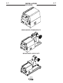
INSTALLATION
BASE MODEL
BENCH MODEL STANDARD DUTY
BENCH MODEL HEAVY DUTY
LF-72
A-17
A-18
A-18
INSTALLATION
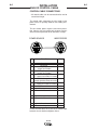
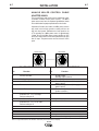
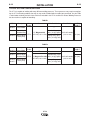
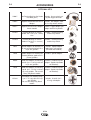
TYPICAL SYSTEM CONFIGURATIONS
The LF-72 is capable of welding with many different welding processes. These processes may require reconfiguring the LF-72 with other products that may or may not be included with the model you purchased. Use the Table
1 and 2 below to identify the basic items which are included in the LF-72 to utilize the various Welding Processes
that the machine is capable of controlling.
TABLE 1
PART NO.
Description
K2327-1
Base Model
K2327-2
Bench Model,
Standard Duty
K2327-3
Bench Model,
Heavy Duty
Wire
Feeder
Wire Reel Stand
Gun
Drive Roll Kit
CONTROL
CABLE
--Standard duty, up to
44 lb. (20 kg) spools. .035-.045 combo
15', Magnum 400,
LF-72 .035-.045 (0.9-1.2 mm)
(0.9-1.2 mm)
Heavy Duty, up to
60 lb. (27.2 kg) coils.
10’ (3m)
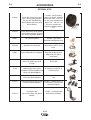
TABLE 2
PART NO.
Description
K2327-4
Base Model
K2327-5
K2327-6
K2327-7
Wire
Feeder
Gun
Wire Reel Stand
---
---
Drive Roll Kit
Bench Model,
Standard duty, up to
Standard Duty LF-72 15’, Magnum Pro 350 44 lb. (20 kg) spools. .035-.045 combo
.035-.045 (0.9-1.2 mm)
(0.9-1.2 mm)
Bench Model,
Heavy Duty, up to
Heavy Duty
60 lb. (27.2 kg) coils.
LF-72
CONTROL
CABLE
---
10’ (3m)
B-1
B-1
OPERATION
SAFETY PRECAUTIONS
Read this entire section of operating instructions
before operating the machine.
WARNING
ELECTRIC SHOCK can kill.
• Unless using cold feed feature,
when feeding with the gun trigger,
the electrode and drive mechanism
are always electrically energized
and could remain energized several
seconds after welding ceases.
• Do not touch electrically live parts or electrodes
with your skin or wet clothing.
• Insulate yourself from the work and ground.
• Always wear dry insulating gloves.
------------------------------------------------------------ONLY QUALIFIED PERSONS SHOULD INSTALL,
USE OR SERVICE THIS EQUIPMENT. READ AND
FOLLOW THE MANUFACTURER’S INSTRUCTIONS, EMPLOYER’S SAFETY PRACTICES AND
MATERIAL SAFETY DATA SHEETS (MSDS) FOR
CONSUMABLES.
The serviceability of a product or structure utilizing
the LF-72 wire feeder is and must be the sole
responsibility of the builder/user. Many variables
beyond the control of The Lincoln Electric Company
affect the results obtained in using the LF-72 wire
feeder. These variables include, but are not limited
to, welding procedure, plate chemistry and temperature, weldment design, fabrication methods and service requirements. The available range of the LF-72
wire feeder may not be suitable for all applications,
and the builder/user is and must be solely responsible for welding settings.
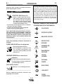
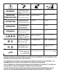
GRAPHIC SYMBOLS THAT APPEAR ON
THIS MACHINE OR IN THIS MANUAL
COLD FEED
POSITIVE OUTPUT
NEGATIVE OUTPUT
----------------------------------------------------------READ THIS WARNING, PROTECT YOURSELF &
OTHERS.
PROTECTIVE
GROUND
FUMES AND GASES can be dangerous.
• Keep your head out of fumes.
• Use ventilation or exhaust at the
arc, or both,to keep fumes and
gases from your breathing zone and
general area.
WARNING OR
CAUTION
DANGEROUS
VOLTAGE
SHOCK
HAZARD
WELDING SPARKS can cause fire or
explosion.
• Do not weld near flammable material.
• Do not weld on containers which have
held flammable material.
ARC RAYS can burn.
WELDING
FUMES
EXPLOSION
• Wear eye, ear, and body protection.
----------------------------------------------------------Observe additional guidelines detailed in the
beginning of this manual.
LF-72
GAS INPUT
WORK
CONNECTION
B-2
B-2
OPERATION
PROCESS LIMITATIONS
COMMON WELDING ABBREVIATIONS
FCAW (Cable Innershield or Outershield)
• Flux Core Arc Welding
• Rated for up to 1/16(1.6 mm) solid electrode and
5/64 (2.0 mm) cored electrode.
• The maximum WFS is 800 in/min (20.3 M/min).
• The LF-72 is not recommended for GMAW-Pulse
(synergic), GTAW, GTAW-Pulse, SAW, CAG,
SMAW.
• Do not use push-pull equipment with the LF-72.
• For K2327-2, -5 Bench model, std. duty: Maximum
spool size = 44 lb. (20 kg); 12 inch (300mm) diameter; 4 inch (100mm)
• For K2327-3, -6, -7 Bench model, heavy duty:
Maximum spool size = 60 lb. (27.2 kg)
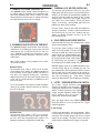
PRODUCT DESCRIPTION
REQUIRED EQUIPMENT
General Physical Description
Lincoln’s LF-72 is designed for use with the CV and
DC family of power sources. These include:
WFS
• Wire Feed Speed
CV
• Constant Voltage
GMAW (MIG)
• Gas Metal Arc Welding
The LF-72 is optimized for .035 through .045 (0.9mm
through 1.2mm) GMAW welding. The powerful 2 roll
drive, heavy duty enclosure and wire reel stand combine to make an easy to install, easy to use wire feeder for everyday welding. Powering the wire drive is a
high performance motor gearbox. A heavy duty
hinged door opens easily, which provides an ample
amount of room for assembling precision drive components and the welding gun. Also under the door is a
convenient storage tray for contact tips and tools.
Three packages are available. The basic unit consists
of the wire drive box housing. The standard duty
bench model targets users of 12" (305 mm)diameter
spools. The heavy duty bench model satisfies the
needs of customers using 60 lb (27.2 kg) spools.
General Functional Description
• CV-305
• CV-400
• CV-655
• DC-400
• DC-600
• Invertec™ V350
• Invertec™ V450
EQUIPMENT LIMITATIONS
• Maximum gun length =25 ft. (7.6m)
• Maximum conduit length = 30 ft. (9.1m)
• Maximum total control cable length = 100ft (31m)
• The LF-72 operates on 42VAC and not 115 VAC
• The K1733-1 wire straightener may not be used with
the LF-72
• Gun bushings are required for welding guns that do
not have a Magnum (Tweco #2-#4 compatible) back
end.
• The LF-72 does not attach to K303 wire reel stands.
• The LF-72 is a highly versatile and economical
choice of industrial feeders. Easy to use features are
a calibrated WFS knob, cold-feed/ gas purge switch
and trigger interlock.
• Several kits are available to expand the LF-72’s
welding capability. The timer kit allows adjustment of
burnback and postflow times. The remote voltage
control kit includes a 0 to 10 dial for setting the welding voltage at the wire feeder. The swivel kit mounts
to the lift bail of a power source and lets the feeder
freely rotate so the gun cable stays straight.
RECOMMENDED PROCESSES
• GMAW .023-1/16 (0.6 - 1.6 mm) steel electrodes.
• FCAW .035 -5/64 (0.9 - 2.0mm) cored electrodes
LF-72
B-3
B-3
OPERATION
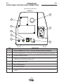
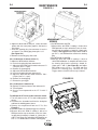
FRONT PANEL CONTROLS AND CONNECTIONS
CASE FRONT CONTROLS
FIGURE B.1
6
1
2
7
3
4
5
8
ITEM
DESCRIPTION
1
Location for Optional Remote Voltage Control (See Accessory Section For Kit Number).
2
Location for Optional Burnback and Postflow Timer Kit (See Accessory Section For Kit Number).
3
Thermal LED, Motor Overload.
4
Cold Feed - Gas Purge Switch, press the switch up to feed wire with weld output off. Press the
switch down for gas flow with weld output off.
5
2 step - Trigger Interlock switch.
6
Wire Feed Speed Knob.
7
Gun Receiver Bushing.
8
Trigger Connector 5-pin amphenol for connecting the MIG gun trigger. See Installation Section
for detail.
LF-72
B-4
OPERATION
B-4
1. REMOTE VOLTAGE CONTROL KIT
3. THERMAL LED, MOTOR OVERLOAD
The optional remote voltage control kit adjusts the
arc voltage from the minimum to the maximum voltage of the welding power source. Rotate the knob
counterclockwise to reduce the arc voltage and rotate
the knob clockwise to raise the arc voltage.
The thermal light illuminates when the wire drive
motor draws too much current. If the thermal light illuminates, the wire drive will automatically shutdown for
up to 30 seconds to allow the motor to cool. To start
welding again, release the gun trigger, inspect the
gun cable, liner (and conduit). Clean and make
repairs as necessary. Start welding again when the
problem has been safely resolved.
For best results, keep the gun cable and conduit as
straight as possible. Perform regular maintenance
and cleaning on the gun liner, conduit and gun.
Always use quality electrode, such as L-50 or L-56
from Lincoln Electric.
4. COLD FEED/GAS PURGE SWITCH
Cold Feed and Gas Purge are combined into a single
spring centered toggle switch.
2. BURNBACK AND POSTFLOW TIMER KIT
The optional Burnback and Postflow Timer Kit gives
control over the shielding gas at the end of the weld
and prepares the end of the wire for the next arc
start. Additional shielding gas protection is often
required when welding aluminum, stainless steel or
exotic alloys.
When stitch welding, set the postflow time to maximum for best results.
Burnback Timer
The burnback timer range is OFF to 0.25 seconds.
The burnback timer controls the additional amount of
time the power source output remains ON after the
wire drive has stopped feeding wire. Burnback
adjustment prevents the wire from sticking to the weld
at the end of a weld and helps to condition the wire
for the next weld.
To activate Cold Feeding, hold the
switch in the UP position. The wire drive
will feed electrode but neither the power
source nor the gas solenoid will be energized. Adjust the speed of cold feeding
by rotating the WFS knob. Cold feeding,
or "cold inching" the electrode is useful
for threading the electrode through the gun.
Hold with toggle switch in the DOWN position to activate Gas Purge and let the shielding gas flow. The
gas solenoid valve will energize but neither the power
source output nor the drive motor will be turned on.
The Gas Purge switch is useful for setting the proper
flow rate of shielding gas. Flow meters should
always be adjusted while the shielding gas is flowing.
5. 2 STEP - TRIGGER INTERLOCK SWITCH
To set the burnback time, adjust the knob to approximately 0.03 seconds and then decrease or increase
the time as desired.
The 2 Step - Trigger Interlock switch
changes the function of the gun trigger. 2
Step trigger operation turns welding on
and off in direct response to the trigger.
Trigger Interlock operation allows welding to continue when the trigger is
released for comfort on long welds.
Place the toggle switch in the DOWN position for 2
Step operation or in the UP position for Trigger
Interlock operation.
2 Step Trigger
Postflow Timer
The postflow timer range is OFF to 10 seconds.
Postflow is the time from when the power source output turns OFF until the postflow timer expires. Use
postflow to protect the weld while the weld cools.
2 Step trigger operation is the most common. When
the gun trigger is pulled, the welding power source
energizes the electrode output and the wire feeder
feeds wire for welding. The power source and wire
feeder continue welding until the trigger is released.
LF-72
B-5
OPERATION
Trigger Interlock
Trigger Interlock operation provides for operator comfort when making long welds. When the gun trigger is
first pulled, the welding power source energizes the
output and the wire feeder feeds wire for welding.
The gun trigger is then released while the weld is
made. To stop welding, the gun trigger is pulled
again, and when it is released the welding power
source output turns off and the wire feeder stops
feeding wire.
CAUTION
• If the arc goes out while welding with
trigger interlock operation, the electrode output from the welding power
source remains energized and the
wire feeder will continue to feed wire
until the gun trigger is again pulled
and then released.
------------------------------------------------------------------------
6. WIRE FEED SPEED KNOB
The large, calibrated wire feed speed knob makes for
easy and accurate adjustment of the wire feed speed.
The knob rotates 3/4 turn. Turn the knob clockwise to
increase the wire feed speed, and counter clockwise
to reduce the wire feed speed.
The wire feed speed range is 50 to 800 in/min (1.27 20.3 m/min).
7. GUN RECEIVER BUSHING (K1500-2)
(K1500-2 bushing is standard on all LF-72's)
This Gun Receiver Bushing is used with Lincoln gun
connectors, also with Magnum 200/300/400 guns and
compatible with Tweco® #4).
8. TRIGGER CONNECTOR 5-PIN AMPHENOL
This is used for connecting the MIG gun trigger.
See Installation Section for detail.
LF-72
B-5
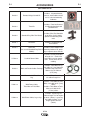
C-1
ACCESSORIES
OPTIONAL KITS:
K2329-1
Remote Voltage Control Kit.
K2330-1
Timer Kit.
K2328-1
Standard Duty Wire Reel Stand.
K2331-1
Lift Bail Kit.
K2332-1
K1796-xx
K1803-1
K1840-xx
K1841-xx
K1842-xx
Includes: 10k potentiometer,
harness, knob and decal with
a 0-10 scale and mounting
hardware.
Includes: Panel and harness
for adjusting burnback and
postflow times.
Includes: Wire Reel Stand for
up to 44 lbs (20 kg) spools,
Spindle and mounting hardware.
Includes: Insulated lift bail
and hardware.
Swivel Kit.
Includes: Swivel adapter and
(for use with Standard Duty Bench mounting hardware for attachModels)
ing to a power source lift bale.
Co-Axial Power Cable.
Includes: Coaxial weld cable
of length "xx". Ends of the
weld cable have lug connections. Use for Pulse or STT
welding.
Includes: Twist-Mate to Lug
2/0 cable 14' (1.2m) long with
Work and Feeder Cables Package.
Ground Clamp, and TwistMate to Lug 2/0 Cable 9'
(2.7m) long.
Weld Power Cable, Twist-Mate to
Lug.
Includes: Twist-Mate to Lug,
1/0 cable of length "xx".
Weld Power Cable,
Twist-Mate to Twist-Mate.
Includes: Twist-Mate to TwistMate, 1/0 Cable for 25' (7.6m)
cables.
Includes: Twist-Mate to TwistMate, 2/0 Cable for 50'
(15.2m) cables.
Weld Power Cable, Lug to Lug.
Includes: Lug to Lug, 3/0
Cable of length "xx" for lengths
up to 60' (18.3m). Lug to Lug,
4/0 Cable of length "xx" for
lengths greater than 60'
(18.3m).
LF-72
C-1
C-2
ACCESSORIES
OPTIONAL KITS:
Includes: 14 pin to 14 pin wire
feeder to power source control
cable.
K1797-xx
Control Cable.
K2335-1
Adapter for Miller Power Sources.
K1520-1
42 Volt Transformer Kit.
K1798
Adapter Cable for Control Cable to
Terminal Strip Power Sources.
Includes:
K910-1
Ground Clamp.
Includes: One 300 Amp
Ground Clamp.
K910-2
Ground Clamp.
Includes: One 500 Amp
Ground Clamp.
K1500-1
Includes: Adapter control
cable for connecting a Lincoln
42 VAC wire feeder to a 24
VAC Miller power source.
Includes: One transformer kit
for operating a 42 VAC wire
feeder on a power source supplying only 115 VAC.
Includes: Gun receiver bushGun Receiver Bushing (for guns
ing, set screw and hex key
with K466-1 Lincoln gun connecwrench.
tors; Innershield and Subarc guns.)
Gun Receiver Bushing (for guns with Includes: Gun receiver bushK466-2, K466-10 Lincoln gun con- ing with hose nipple, set screw
K1500-2
and hex key wrench.
(standard on all nectors; Magnum 200/300/400 guns
and compatible with Tweco® #4.)
LF-72's)
K1500-3
K1500-4
K1500-5
Gun Receiver Bushing (for guns
Includes: Gun receiver bushwith K613-7 Lincoln gun connec- ing with hose nipple, set screw
tors; Magnum 550 guns and comand hex key wrench.
patible with Tweco® #5.)
Gun Receiver Bushing (for gun
Includes: Gun receiver bushwith K466-3 Lincoln gun connec- ing with hose nipple, set screw
tors; compatible with Miller® guns.)
and hex key wrench.
Gun Receiver Bushing (compatible
with Oxo® guns.)
Includes: Gun receiver bushing with hose nipple, 4 guide
tubes, set screw and hex key
wrench.
LF-72
C-2
C-3
ACCESSORIES
OPTIONAL KITS:
K489-7
Gun Receiver Bushing (for Lincoln
Fast-Mate guns.)
Includes: Gun receiver bushing with trigger connector.
K466-2
Magnum 200/300/400 to K1500-2
Adapter.
Includes: Gun adapter, cotter
pin, hex key wrench, wrench.
K613-7
Magnum 550 to K1500-3 Adapter
Lincoln Conduit.
Includes: Trigger adapter, gun
adapter and hex key wrench.
K1546-1
Incoming Bushing, for Lincoln
Conduit .025- 1/16" (0.6 - 1.6mm)
wire.
Includes: Incoming bushing
and hex key wrench.
K1546-2
Incoming Bushing, for Lincoln
Conduit 1/16-1/8" (1.6 - 3.2 mm )
wire.
Includes: Incoming bushing
and hex key wrench.
K435
Spindle Adapter, for mounting 14
lb. (6.4 kg) Innershield Coils on 2
in (51 mm) spindles.
Includes: Spindle Adapter
made from 2 coil retainers.
(Electrode not included.)
K468
Spindle Adapter, for mounting 8in
(203mm) diameter spools on 2 in
(51 mm) spindles.
Includes: Spindle Adapter.
K363P
Readi-Reel Adapter, for mounting
23-30 lb. (10.4 - 13.6 kg) reels to 2
in (51 mm) spindles.
Includes: Readi-Reel spool
adapter. (Spool of electrode
not included.)
K438
Readi-Reel Adapter, for mounting
50-60 lb. (22.7 - 27.2 kg) reels to 2
in (51 mm) spindles. For use with
Heavy Duty Bench models.
Includes: Readi-Reel spool
adapter. (Spool of electrode
not included.)
K1504-1
Coil Adapter, for mounting 50-60
lb. (22.7 - 27.2 kg) coils to 2 in (51
mm) spindles.
For use with heavy Duty Bench
models.
Includes: 50-60 lb. (22.7 27.2 kg) coil adapter.
LF-72
C-3
C-4
ACCESSORIES
OPTIONAL KITS:
Includes: Cover, backing
plate, wire conduit, incoming
bushing for .025 - 1/16" (0.6 1.6 mm) wire, incoming bushing for 1/16" - 1/8" (1.6 - 3.2
mm) wire, thumb screw,
mounting hardware and hex
key.
K1634-1
Plastic Wire Cover for 30-44 lb.
(13.6 - 20.0 kg) Wire packages.
(For use with Standard Duty
Bench Models and Heavy Duty
Bench Models.)
K1634-2
Plastic Wire Cover for up to 60 lb.
(27.2kg) Wire packages. (For use
with Heavy Duty Bench Models.)
K659-1
Gas Guard Regulator
3000290
Adjustable Gas Regulator
K586-1
Deluxe Adjustable Gas Regulator
K1524-3
Heavy Duty Universal Wire Reel
Stand. For spools up to 60 lb.
(27.2kg)
Includes: Heavy Duty Wire
Reel Stand.
4 Wheeled Wire Feeder
Undercarriage (For use with
Standard Duty Bench Models and
Heavy Duty Bench Models.)
Includes: Undercarriage with
8" (203mm) rear wheels, 4"
(102mm)casters.
K1557-1
Swivel Platform (for use with
Heavy Duty Bench Models)
Includes: Swivel Platform and
Tray.
K1556-1
Light Duty Caster Kit (for use with
Heavy Duty Bench Models)
Includes: 2 Swivel Casters, 2
Fixed Casters, brackets and
mounting hardware.
Insulated Lift Bail
(for use with Heavy Duty Bench
Models)
Includes: Insulated Lift Bail
and mounting hardware.
K163
K1555-1
Includes: Gas Guard
Regulator and adjustment key.
Includes: Gas Regulator for
Mixed Gases and 10' (3.0m)
Hose.
Includes: Deluxe Gas
Regulator for Mixed Gases,
Adapter for CO2 and 10'
(3.0m) Hose.
LF-72
C-4
D-1
D-1
MAINTENANCE
CALIBRATION SPECIFICATION
MAINTENANCE
WARNING
Safety Precautions
ELECTRIC SHOCK can kill.
WARNING
ELECTRIC SHOCK can kill.
• Do not touch electrically live parts
such as output terminals or internal wiring.
• When inching with gun trigger, electrode and
drive mechanism are “hot” to work and ground
and could remain energized several seconds
after the gun trigger is released.
• Turn OFF input power at welding power source
before installation or changing drive roll and/or
guide tubes.
• Welding power source must be connected to
system ground per the National Electrical Code
or any applicable local codes.
• Only qualified personnel should perform maintenance work.
-----------------------------------------------------------------------Observe all additional Safety Guidelines detailed
throughout this manual.
ROUTINE MAINTENANCE
• Clean and tighten all weld terminals.
• Inspect all weld cables, control cables, gun cables
and shielding gas hoses. Repair or replace as necessary.
PERIODIC MAINTENANCE
• Clean drive roll grooves.
• Blow out or vacuum the inside of the feeder.
• Do not touch electrically live
parts.
• When inching with the gun trigger,
electrode, wire drive motor and
drive mechanism are "hot" to
work and ground and could
remain energized several seconds
after the gun trigger is released.
• Welding power source must be connected to
system ground per the National Electrical Code
or any applicable local codes.
• Only qualified personnel should perform maintenance work.
-----------------------------------------------------------------------Calibration of the LF-72 may be required when the p.c.
board, potentiometer or motor is replaced or serviced.
Calibration matches the scale on the name plate to
the actual wire feed speed.
To verify if calibration is necessary:
1. Turn off power to the LF-72.
2. Assemble .045 drive rolls, inner guide and the
outer guide into the drive. Remove the gun from
the wire feeder if assembled.
3. Load .045 wire into the drive. Cut the wire flush
with the end of the gun bushing.
4. Set the WFS knob to 300 ipm.
5. Using the COLD FEED switch, feed wire for 10
seconds.
6. Cut the wire flush with the end of the gun bushing.
Measure the length of the wire. If the wire measures 50 ± 2.5 inches then calibration is not
required.
Tools required applies to all codes that follow:
5/16" nut driver
3/4" open end wrench
WFS meter or RPM meter
Shorting plug. The shorting plug shorts pins 1
& 5 of connector J2 on the p.c. board. J2 is a
6 pin molex connector.
To calibrate the LF-72 for Codes 11075 thru 11293:
1. Turn off power to the LF-72.
2. Disconnect the electrode lead from the feed plate
and from the welding power source.
3. Remove the 5 screws securing the wraparound.
(The door is not shown for clarity. “See Figure
D.1”)
4. Open the idle arm.
5. Turn power on to the LF-72.
LF-72
D-2
D-2
MAINTENANCE
FIGURE D.1
6. Adjust the WFS knob to 300 ipm. Center the knob
pointer with the name plate graphics. Activate the
gun trigger.
7. Insert the shorting plug into connector J2 on the
p.c. board. The shorting plug shorts pins 1 & 5.
(See Figure D.2)
8. Remove the shorting plug. Set aside.
(For Codes below 11289 use 9 thru 17)
9. Adjust the WFS knob to minimum.
10. Insert the shorting plug into connector J2.
11. Adjust the WFS knob until the motor measures 51
± 5.5 ipm. (9.5 ± 1.0 rpm).
12. Remove the shorting plug.
13. Adjust the WFS knob to maximum.
14. Insert the shorting plug into connector J2.
15. Adjust the WFS until the motor measures 793 ±
5.5 ipm (146.7 ± 1.0 rpm.)
16. Remove the shorting plug.
17. Release the gun trigger.
6. Set WFS Knob to 300 IPM.
7. Measure drive role RPM. If reading is 54.8 to 56.0
RPM proceed to step 8 otherwise insert the shorting plug into the control p.c. board J2 (shorts pins
1 and 5.) See Figure D.2 and adjust WFS Knob to
get 55.4 +/- 0.6 RPM and then remove the shorting
plug.
8. Set WFS Knob to 800 IPM.
9. Measure drive role RPM. If reading is 146.4 to
148.4 RPM calibration is complete otherwise insert
the shorting plug into the control p.c. board J2.
(shorts pins 1 and 5.) See Figure D.2 and adjust
WFS Knob to get 147.4 +/- 1.0 RPM and then
remove the shorting plug. Release the Gun
Trigger, connect J2 of the harness to p.c. board.
FIGURE D.2
(For Codes above 11290 use 18)
18. Replace P2 from the harness into connector J2.
19. Turn off power.
20. Secure the wraparound to the LF-72 with 5
screws.
To calibrate the LF-72 for Codes 11606 thru 11609:
1. Turn off power to the LF-72 and welding power
source.
2. Disconnect the electrode lead from the feed plate
and from the welding power source.
3. Remove the wraparound from the LF-72, See
Figure D.1.
4. Set WFS Knob to 50 IPM and trigger the machine.
5. Measure drive role RPM. If reading is 8.9 to 9.2
RPM proceed to step 6 otherwise insert the shorting plug into the control p.c. board J2 (shorts pins 1
and 5.) See Figure D.2 and adjust WFS Knob to get
9.05 +/- 0.15 RPM and then remove shorting plug.
LF-72
J2 CONNECTOR
E-1
TROUBLESHOOTING
WARNING
E-1
ELECTRIC SHOCK can kill.
• Turn the input power OFF at the welding power source before installation or changing
drive rolls and/or guides.
• Do not touch electrically live parts.
• When inching with the gun trigger, electrode and drive mechanism are "hot" to work and
ground and could remain energized several seconds after the gun trigger is released.
• Welding power source must be connected to system ground per the National Electrical
Code or any applicable local codes.
• Only qualified personnel should perform maintenance work.
Observe all additional Safety Guidelines detailed throughout this manual.
HOW TO USE TROUBLESHOOTING GUIDE
Service and Repair should only be performed by Lincoln Electric Factory Trained Personnel.
Unauthorized repairs performed on this equipment may result in danger to the technician and
machine operator and will invalidate your factory warranty. For your safety and to avoid Electrical
Shock, please observe all safety notes and precautions detailed throughout this manual.
__________________________________________________________________________
This Troubleshooting Guide is provided to help you
locate and repair possible machine malfunctions.
Simply follow the three-step procedure listed below.
Step 1. LOCATE PROBLEM (SYMPTOM).
Look under the column labeled “PROBLEM (SYMPTOMS)”. This column describes possible symptoms
that the machine may exhibit. Find the listing that
best describes the symptom that the machine is
exhibiting.
Step 3. RECOMMENDED COURSE OF ACTION
This column provides a course of action for the
Possible Cause, generally it states to contact your
local Lincoln Authorized Field Service Facility.
If you do not understand or are unable to perform the
Recommended Course of Action safely, contact your
local Lincoln Authorized Field Service Facility.
Step 2. POSSIBLE CAUSE.
The second column labeled “POSSIBLE CAUSE” lists
the obvious external possibilities that may contribute
to the machine symptom.
CAUTION
If for any reason you do not understand the test procedures or are unable to perform the tests/repairs safely, contact your
Local Lincoln Authorized Field Service Facility for technical troubleshooting assistance before you proceed.
LF-72
E-2
E-2
TROUBLESHOOTING
Observe all Safety Guidelines detailed throughout this manual
PROBLEMS
(SYMPTOMS)
POSSIBLE AREAS OF
MISADJUSTMENTS(S)
RECOMMENDED
COURSE OF ACTION
OUTPUT PROBLEMS
The wire feeder does not feed wire 1. Verify the power source is turned
and the drive rolls do not spin.
on.
2. Verify the circuit breaker for the
wire feeder on the power source
has not tripped.
3. Check that the gun trigger is
operating properly.
4. If the motor thermal LED is illuminated, wait approximately 1
minute before welding again.
Inspect the gun for feeding problems.
5. Verify power is being supplied to
the wire feeder.
The wire feeds erratically, or the 1. Verify the correct drive rolls and
inner wire guide are installed in
Motor Thermal LED lights.
the wire drive.
2. Check for sharp bends in the gun
liner.
3. Examine the contact tip for wear
and proper size. Replace as necessary.
4. Check the gun liner. The welding
electrode should slide easily
through the gun.
5. Verify the proper gun liner is
installed.
6. Adjust the pressure arm.
7. On bench models, make sure the
brake tension is not too tight.
8. If using a wire conduit, verify the
wire slides easily through the
conduit.
If all recommended possible areas of
misadjustment have been checked
and the problem persists, Contact
your local Lincoln Authorized
Field Service Facility.
The wire continues to feed when the 1. Check if the 2 step/Trigger
trigger is released.
Interlock switch is in the TRIGGER INTERLOCK position.
2. Verify operation of the gun trigger.
No shielding gas
1. Verify the gas supply is turned on
and not empty.
2. Check the gas hose for cuts.
Make sure it is not crushed.
3. Verify the shielding gas hose is
connected to the gun bushing or
welding gun.
CAUTION
If for any reason you do not understand the test procedures or are unable to perform the tests/repairs safely, contact your
Local Lincoln Authorized Field Service Facility for technical troubleshooting assistance before you proceed.
LF-72
E-3
E-3
TROUBLESHOOTING
Observe all Safety Guidelines detailed throughout this manual
PROBLEMS
(SYMPTOMS)
POSSIBLE AREAS OF
MISADJUSTMENTS(S)
Variable or "hunting" arc.
1. Check for proper size contact.
Make sure the contact tip is not
worn, free of spatter and not melted.
2. Clean and tighten all electrode
and work connections.
3. Verify the proper polarity is being
used for the weld procedure.
4. Make sure the proper electrode
stick-out is being maintained.
5. Check the gas flow rate and mixture.
6. Verify the gun bushing is tightly to
the wire drive.
7. Verify the gun is tightly mounted
to the gun bushing.
The motor thermal LED illuminates.
1. Check for sharp bends in the gun
liner.
2. Examine the contact tip for wear
and proper size. Replace as necessary.
3. Check the gun liner. The welding
electrode should slide easily
through the gun.
4. Verify the proper gun liner is
installed.
5. Reduce the pressure arm setting.
6. On bench models, make sure the
brake tension is not too tight.
7. If using a wire conduit, verify the
wire slides easily through the
conduit.
RECOMMENDED
COURSE OF ACTION
If all recommended possible areas of
misadjustment have been checked
and the problem persists, Contact
your local Lincoln Authorized
Field Service Facility.
When the gun trigger is pulled, the 1. Check all electrode and work
drive rolls spin but no arc is present.
connections.
2. Verify the gun bushing is tightly to
the wire drive.
3. Verify the gun is tightly mounted
to the gun bushing.
4. Check the control cable and connectors for cuts. Verify that no
pins are broken or bent.
The arc burns back to the tip at the 1. If the timer kit is installed, reduce
end of the weld.
the amount of burnback time.
The gas continues to flow for a long 1. If the timer kit is installed, reduce
time at the end of a weld.
the amount of postflow time.
CAUTION
If for any reason you do not understand the test procedures or are unable to perform the tests/repairs safely, contact your
Local Lincoln Authorized Field Service Facility for technical troubleshooting assistance before you proceed.
LF-72
2
1
8
5
4
3
J1,J14
2
1
LF-72
ARC
CURRENT
M
N
K
L
I
J
G
H
E
F
C
D
A
B
553
4
1
67
42
51
41
50
76A
75A
2
4
77A
6
3
41
41A
N.B.
16
8
L1
580
-
BAFFLE
MOUNTED
RECTIFIER
DIODE
BRIDGE
42
552A
552C
552B
COLOR CODE
BWRU-
BLACK
WHITE
RED
BLUE
575C
551
556
552
B
U
R
TACH
67
J3
1 2
COMMON ANALOG P.C. BOARD
B
J2
563
N.B.
W
J1
576
P5
8
1 2 3 4 5 6
550
554 552A 553
575C
575B
L5
550
5
7
6
551
4
3
2
575B
562
563
1
L2
1 2 3 4 5 6 7 8 9 10 11 12 13 14 15 16
562
577
580
575
L4
N.A. CAVITY NUMBERING SEQUENCE AS VIEWED FROM COMPONENT SIDE OF BOARD.
N.B. CAVITY NUMBERING SEQUENCE AS VIEWED FROM LEAD SIDE OF CONNECTOR.
N.C. TOGGLE SWITCHES AND POTENTIOMETERS SHOWN FROM CONNECTION SIDE OF SWITCH.
N.D. PIN NEAREST THE FLAT EDGE OF LED LENS ALIGNS WITH WHITE LEAD OF LED SOCKET.
NOTES:
J6
SENSE
ARC VOLTAGE
42VAC
REMOTE
VOLTAGE
CONTROL
552
552B
9
1
J2
+
OUTPUT
CONTROL
14 PIN
AMPHENOL
CONNECTOR
TO POWER
SOURCE
GAS
SOLENOID
4
1
J7
GENERAL INFORMATION
ELECTRICAL SYMBOLS PER E1537
605
608
607
587
K
E
W Y
W
2
558 601
559
589
515
606
J14
1 2 3 4 5 6 7 8 9 10 11 12 13 14 15 16
4
B
MOTOR /
GEARBOX
FEED
PLATE
INPUT ELECTRODE
CABLE CONNECTION
6
5
50
41A
N.A.
51
552C
1 2 3 4 5 6 7 8 9 10
P9
P7
J60
576A
577A
75
76
77
575A
L3
606
606A
B
BURNBACK
601 515A 605 607
606A 608
1 2 3 4 5 6 7 8
POST-FLOW
3
77A
N.B.
77
2
4
75
76
1
76A
P8
75A
N.B.
577A
576A
575A
4
3
2
1
577
576
575
3
2
1
3
2
1
N.C.
N.C.
587
589
559
W
B
2-STEP
TRIGGER
INTERLOCK
GAS PURGE
S2
S1
A
L12146
TRIGGER
CONNECTOR
J4
TRIGGER
INPUT
THERMAL LED
E
D
C
B
A
N.A.
TIMER KIT
(OPTIONAL)
REMOTE
CONTROL
VOLTAGE
POTENTIOMETER
(OPTIONAL)
WIRE FEED
SPEED
CONTROL
POTENTIOMETER
COLD FEED
N.B.
558
515A
515
N.D.
554
556
N.C.
10K/2W
N.C.
10K/2W
WIRING DIAGRAM
NOTE: This diagram is for reference only. It may not be accurate for all machines covered by this manual. The specific diagram for a particular code is pasted inside
the machine on one of the enclosure panels. If the diagram is illegible, write to the Service Department for a replacement. Give the equipment code number.
J5,J8
J9,J60
J3
(COMPONENT SIDE OF P.C. BOARD)
CAVITY NUMBERING SEQUENCE
LF-72 FEEDER (11075, 11076, 11077)
F-1
F-1
2
8
5
J1,J14
4
3
LF-72
M
N
K
L
I
J
G
H
E
F
C
D
A
B
553
4
67
42
41
76A
75A
2
4
77A
6
3
41
N.B.
16
8
L1
580
-
BAFFLE
MOUNTED
RECTIFIER
DIODE
BRIDGE
42
552A
552B
COLOR CODE
BWRU-
BLACK
WHITE
RED
BLUE
575C
551
556
552
B
U
R
TACH
67
J3
1 2
COMMON ANALOG P.C. BOARD
J2
563
B
J1
576
N.B.
W
1 2 3 4 5 6
550
554 552A 553
575C
575B
L5
P5
8
6
7
550
551
4
3
2
5
562
575B
563
1
L2
1 2 3 4 5 6 7 8 9 10 11 12 13 14 15 16
562
577
580
575
L4
N.A. CAVITY NUMBERING SEQUENCE AS VIEWED FROM COMPONENT SIDE OF BOARD.
N.B. CAVITY NUMBERING SEQUENCE AS VIEWED FROM LEAD SIDE OF CONNECTOR.
N.C. TOGGLE SWITCHES AND POTENTIOMETERS SHOWN FROM CONNECTION SIDE OF SWITCH.
N.D. PIN NEAREST THE FLAT EDGE OF LED LENS ALIGNS WITH WHITE LEAD OF LED SOCKET.
J6
SENSE
NOTES:
42VAC
REMOTE
VOLTAGE
CONTROL
552
552B
9
1
J2
1
+
OUTPUT
CONTROL
14 PIN
AMPHENOL
CONNECTOR
TO POWER
SOURCE
GAS
SOLENOID
4
1
J7
2
1
GENERAL INFORMATION
ELECTRICAL SYMBOLS PER E1537
605
608
607
587
K
E
W Y
W
2
558 601
559
589
515
606
J14
1 2 3 4 5 6 7 8 9 10 11 12 13 14 15 16
4
B
MOTOR /
GEARBOX
FEED
PLATE
INPUT ELECTRODE
CABLE CONNECTION
P7
J60
75
76
77
575A
576A
577A
L3
606
606A
B
BURNBACK
601 515A 605 607
606A 608
1 2 3 4 5 6 7 8
POST-FLOW
3
77A
N.B.
77
2
4
75
76
1
76A
N.A.
6
5
P8
75A
N.B.
577A
4
575A
576A
3
2
1
577
576
575
3
2
1
3
2
1
N.C.
N.C.
587
589
559
W
B
2-STEP
TRIGGER
INTERLOCK
GAS PURGE
S2
S1
A
L12146-1
TRIGGER
CONNECTOR
J4
TRIGGER
INPUT
THERMAL LED
E
D
C
B
A
N.A.
TIMER KIT
(OPTIONAL)
REMOTE
CONTROL
VOLTAGE
POTENTIOMETER
(OPTIONAL)
WIRE FEED
SPEED
CONTROL
POTENTIOMETER
COLD FEED
N.B.
558
515A
515
N.D.
554
556
N.C.
10K/2W
N.C.
10K/2W
WIRING DIAGRAM
NOTE: This diagram is for reference only. It may not be accurate for all machines covered by this manual. The specific diagram for a particular code is pasted inside
the machine on one of the enclosure panels. If the diagram is illegible, write to the Service Department for a replacement. Give the equipment code number.
J5,J8
J9,J60
J3
1
(COMPONENT SIDE OF P.C. BOARD)
CAVITY NUMBERING SEQUENCE
LF-72 FEEDER (FOR CODES 11209, 11210, 11211 11227)
F-2
F-2
NOTE: This diagram is for reference only. It may not be accurate for all machines covered by this manual. The specific diagram for a particular code is pasted inside
the machine on one of the enclosure panels. If the diagram is illegible, write to the Service Department for a replacement. Give the equipment code number.
F-3
DIAGRAMS
LF-72
Enhanced Diagram
F-3
NOTE: This diagram is for reference only. It may not be accurate for all machines covered by this manual. The specific diagram for a particular code is pasted inside
the machine on one of the enclosure panels. If the diagram is illegible, write to the Service Department for a replacement. Give the equipment code number.
F-4
DIAGRAMS
LF-72
F-4
F-5
DIMENSION PRINTS
BENCH MODEL
BENCH MODEL STANDARD DUTY
LF-72
F-5
F-6
DIMENSION PRINTS
BENCH MODEL HEAVY DUTY
LF-72
F-6
● Do not touch electrically live parts or
WARNING
Spanish
AVISO DE
PRECAUCION
French
ATTENTION
German
WARNUNG
Portuguese
ATENÇÃO
● Keep flammable materials away.
● Wear eye, ear and body protection.
● Mantenga el material combustible
● Protéjase los ojos, los oídos y el
electrode with skin or wet clothing.
● Insulate yourself from work and
ground.
● No toque las partes o los electrodos
bajo carga con la piel o ropa mojada.
● Aislese del trabajo y de la tierra.
● Ne laissez ni la peau ni des vête-
ments mouillés entrer en contact
avec des pièces sous tension.
● Isolez-vous du travail et de la terre.
● Berühren Sie keine stromführenden
fuera del área de trabajo.
● Gardez à l’écart de tout matériel
inflammable.
● Entfernen Sie brennbarres Material!
Teile oder Elektroden mit Ihrem
Körper oder feuchter Kleidung!
● Isolieren Sie sich von den
Elektroden und dem Erdboden!
● Não toque partes elétricas e elec-
trodos com a pele ou roupa molhada.
● Isole-se da peça e terra.
cuerpo.
● Protégez vos yeux, vos oreilles et
votre corps.
● Tragen Sie Augen-, Ohren- und Kör-
perschutz!
● Mantenha inflamáveis bem guarda-
dos.
● Use proteção para a vista, ouvido e
corpo.
Japanese
Chinese
Korean
Arabic
READ AND UNDERSTAND THE MANUFACTURER’S INSTRUCTION FOR THIS EQUIPMENT AND THE CONSUMABLES TO BE
USED AND FOLLOW YOUR EMPLOYER’S SAFETY PRACTICES.
SE RECOMIENDA LEER Y ENTENDER LAS INSTRUCCIONES DEL FABRICANTE PARA EL USO DE ESTE EQUIPO Y LOS
CONSUMIBLES QUE VA A UTILIZAR, SIGA LAS MEDIDAS DE SEGURIDAD DE SU SUPERVISOR.
LISEZ ET COMPRENEZ LES INSTRUCTIONS DU FABRICANT EN CE QUI REGARDE CET EQUIPMENT ET LES PRODUITS A
ETRE EMPLOYES ET SUIVEZ LES PROCEDURES DE SECURITE DE VOTRE EMPLOYEUR.
LESEN SIE UND BEFOLGEN SIE DIE BETRIEBSANLEITUNG DER ANLAGE UND DEN ELEKTRODENEINSATZ DES HERSTELLERS. DIE UNFALLVERHÜTUNGSVORSCHRIFTEN DES ARBEITGEBERS SIND EBENFALLS ZU BEACHTEN.
● Keep your head out of fumes.
● Use ventilation or exhaust to
● Turn power off before servicing.
● Do not operate with panel open or
guards off.
remove fumes from breathing zone.
● Los humos fuera de la zona de res-
piración.
● Mantenga la cabeza fuera de los
humos. Utilice ventilación o
aspiración para gases.
● Gardez la tête à l’écart des fumées.
● Utilisez un ventilateur ou un aspira-
● Desconectar el cable de ali-
mentación de poder de la máquina
antes de iniciar cualquier servicio.
● Débranchez le courant avant l’entre-
tien.
teur pour ôter les fumées des zones
de travail.
● Vermeiden Sie das Einatmen von
Schweibrauch!
● Sorgen Sie für gute Be- und
Entlüftung des Arbeitsplatzes!
● Mantenha seu rosto da fumaça.
● Use ventilação e exhaustão para
remover fumo da zona respiratória.
● Strom vor Wartungsarbeiten
● No operar con panel abierto o
guardas quitadas.
● N’opérez pas avec les panneaux
ouverts ou avec les dispositifs de
protection enlevés.
● Anlage nie ohne Schutzgehäuse
abschalten! (Netzstrom völlig öffnen; Maschine anhalten!)
oder Innenschutzverkleidung in
Betrieb setzen!
● Não opere com as tampas removidas.
● Desligue a corrente antes de fazer
● Mantenha-se afastado das partes
serviço.
● Não toque as partes elétricas nuas.
moventes.
● Não opere com os paineis abertos
ou guardas removidas.
WARNING
Spanish
AVISO DE
PRECAUCION
French
ATTENTION
German
WARNUNG
Portuguese
ATENÇÃO
Japanese
Chinese
Korean
Arabic
LEIA E COMPREENDA AS INSTRUÇÕES DO FABRICANTE PARA ESTE EQUIPAMENTO E AS PARTES DE USO, E SIGA AS
PRÁTICAS DE SEGURANÇA DO EMPREGADOR.
• World's Leader in Welding and Cutting Products •
• Sales and Service through Subsidiaries and Distributors Worldwide •
Cleveland, Ohio 44117-1199 U.S.A. TEL: 216.481.8100 FAX: 216.486.1751 WEB SITE: www.lincolnelectric.com