1
RETURN TO MAIN MENU
IM474-E
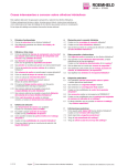
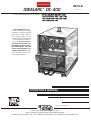
IDEALARC ® DC-400
For use with machines having Code Numbers:
February, 2011
9847 thru 9852, 9854, 9855, 9857, 10008,
10275, 10276, 10859, 10880, 11083, 11084,
11277, 11278, 11279 11348, 11349, 11350,
11351, 11352, 11353, 11567
Safety Depends on You
Lincoln arc welding and cutting
equipment is designed and built
with safety in mind. However,
your overall safety can be
increased by proper installation
... and thoughtful operation on
your part. DO NOT INSTALL,
OPERATE OR REPAIR THIS
EQUIPMENT WITHOUT READING THIS MANUAL AND THE
SAFETY PRECAUTIONS CONTAINED THROUGHOUT. And,
most importantly, think before
you act and be careful.
OPERATOR’S MANUAL
Copyright © Lincoln Global Inc.
• World's Leader in Welding and Cutting Products •
• Sales and Service through Subsidiaries and Distributors Worldwide •
Cleveland, Ohio 44117-1199 U.S.A. TEL: 216.481.8100 FAX: 216.486.1751 WEB SITE: www.lincolnelectric.com
i
i
SAFETY
WARNING
CALIFORNIA PROPOSITION 65 WARNINGS
Diesel engine exhaust and some of its constituents
are known to the State of California to cause cancer, birth defects, and other reproductive harm.
The Above For Diesel Engines
The engine exhaust from this product contains
chemicals known to the State of California to cause
cancer, birth defects, or other reproductive harm.
The Above For Gasoline Engines
ARC WELDING CAN bE HAzARDOUS. PROTECT YOURSELF AND OTHERS FROM POSSIbLE SERIOUS INJURY OR DEATH.
KEEP CHILDREN AWAY. PACEMAKER WEARERS SHOULD CONSULT WITH THEIR DOCTOR bEFORE OPERATING.
Read and understand the following safety highlights. For additional safety information, it is strongly recommended that you
purchase a copy of “Safety in Welding & Cutting - ANSI Standard Z49.1” from the American Welding Society, P.O. Box
351040, Miami, Florida 33135 or CSA Standard W117.2-1974. A Free copy of “Arc Welding Safety” booklet E205 is available
from the Lincoln Electric Company, 22801 St. Clair Avenue, Cleveland, Ohio 44117-1199.
bE SURE THAT ALL INSTALLATION, OPERATION, MAINTENANCE AND REPAIR PROCEDURES ARE
PERFORMED ONLY bY QUALIFIED INDIVIDUALS.
FOR ENGINE
powered equipment.
1.h. To avoid scalding, do not remove the
radiator pressure cap when the engine is
hot.
1.a. Turn the engine off before troubleshooting and maintenance
work unless the maintenance work requires it to be running.
____________________________________________________
1.b. Operate engines in open, well-ventilated
areas or vent the engine exhaust fumes
outdoors.
____________________________________________________
1.c. Do not add the fuel near an open flame
welding arc or when the engine is running.
Stop the engine and allow it to cool before
refueling to prevent spilled fuel from vaporizing on contact with hot engine parts and
igniting. Do not spill fuel when filling tank. If
fuel is spilled, wipe it up and do not start
engine until fumes have been eliminated.
____________________________________________________
1.d. Keep all equipment safety guards, covers and devices in
position and in good repair.Keep hands, hair, clothing and
tools away from V-belts, gears, fans and all other moving
parts when starting, operating or repairing equipment.
____________________________________________________
1.e. In some cases it may be necessary to remove safety
guards to perform required maintenance. Remove
guards only when necessary and replace them when the
maintenance requiring their removal is complete.
Always use the greatest care when working near moving
parts.
___________________________________________________
1.f. Do not put your hands near the engine fan.
Do not attempt to override the governor or
idler by pushing on the throttle control rods
while the engine is running.
___________________________________________________
1.g. To prevent accidentally starting gasoline engines while
turning the engine or welding generator during maintenance
work, disconnect the spark plug wires, distributor cap or
magneto wire as appropriate.
ELECTRIC AND
MAGNETIC FIELDS
may be dangerous
2.a. Electric current flowing through any conductor causes
localized Electric and Magnetic Fields (EMF). Welding
current creates EMF fields around welding cables and
welding machines
2.b. EMF fields may interfere with some pacemakers, and
welders having a pacemaker should consult their physician
before welding.
2.c. Exposure to EMF fields in welding may have other health
effects which are now not known.
2.d. All welders should use the following procedures in order to
minimize exposure to EMF fields from the welding circuit:
2.d.1. Route the electrode and work cables together - Secure
them with tape when possible.
2.d.2. Never coil the electrode lead around your body.
2.d.3. Do not place your body between the electrode and
work cables. If the electrode cable is on your right
side, the work cable should also be on your right side.
2.d.4. Connect the work cable to the workpiece as close as
possible to the area being welded.
2.d.5. Do not work next to welding power source.
ii
ii
SAFETY
ELECTRIC SHOCK can
kill.
3.a. The electrode and work (or ground) circuits
are electrically “hot” when the welder is on.
Do not touch these “hot” parts with your bare
skin or wet clothing. Wear dry, hole-free
gloves to insulate hands.
3.b. Insulate yourself from work and ground using dry insulation.
Make certain the insulation is large enough to cover your full
area of physical contact with work and ground.
In addition to the normal safety precautions, if welding
must be performed under electrically hazardous
conditions (in damp locations or while wearing wet
clothing; on metal structures such as floors, gratings or
scaffolds; when in cramped positions such as sitting,
kneeling or lying, if there is a high risk of unavoidable or
accidental contact with the workpiece or ground) use
the following equipment:
• Semiautomatic DC Constant Voltage (Wire) Welder.
• DC Manual (Stick) Welder.
• AC Welder with Reduced Voltage Control.
3.c. In semiautomatic or automatic wire welding, the electrode,
electrode reel, welding head, nozzle or semiautomatic
welding gun are also electrically “hot”.
3.d. Always be sure the work cable makes a good electrical
connection with the metal being welded. The connection
should be as close as possible to the area being welded.
3.e. Ground the work or metal to be welded to a good electrical
(earth) ground.
3.f. Maintain the electrode holder, work clamp, welding cable and
welding machine in good, safe operating condition. Replace
damaged insulation.
3.g. Never dip the electrode in water for cooling.
3.h. Never simultaneously touch electrically “hot” parts of
electrode holders connected to two welders because voltage
between the two can be the total of the open circuit voltage
of both welders.
3.i. When working above floor level, use a safety belt to protect
yourself from a fall should you get a shock.
ARC RAYS can burn.
4.a. Use a shield with the proper filter and cover
plates to protect your eyes from sparks and
the rays of the arc when welding or observing
open arc welding. Headshield and filter lens
should conform to ANSI Z87. I standards.
4.b. Use suitable clothing made from durable flame-resistant
material to protect your skin and that of your helpers from
the arc rays.
4.c. Protect other nearby personnel with suitable, non-flammable
screening and/or warn them not to watch the arc nor expose
themselves to the arc rays or to hot spatter or metal.
FUMES AND GASES
can be dangerous.
5.a. Welding may produce fumes and gases
hazardous to health. Avoid breathing these
fumes and gases. When welding, keep
your head out of the fume. Use enough
ventilation and/or exhaust at the arc to keep
fumes and gases away from the breathing zone. When
welding with electrodes which require special
ventilation such as stainless or hard facing (see
instructions on container or MSDS) or on lead or
cadmium plated steel and other metals or coatings
which produce highly toxic fumes, keep exposure as
low as possible and within applicable OSHA PEL and
ACGIH TLV limits using local exhaust or mechanical
ventilation. In confined spaces or in some circumstances, outdoors, a respirator may be required.
Additional precautions are also required when welding
on galvanized steel.
5. b. The operation of welding fume control equipment is affected
by various factors including proper use and positioning of
the equipment, maintenance of the equipment and the specific welding procedure and application involved. Worker
exposure level should be checked upon installation and
periodically thereafter to be certain it is within applicable
OSHA PEL and ACGIH TLV limits.
5.c. Do not weld in locations near chlorinated hydrocarbon vapors
coming from degreasing, cleaning or spraying operations.
The heat and rays of the arc can react with solvent vapors to
form phosgene, a highly toxic gas, and other irritating products.
3.j. Also see Items 6.c. and 8.
5.d. Shielding gases used for arc welding can displace air and
cause injury or death. Always use enough ventilation,
especially in confined areas, to insure breathing air is safe.
5.e. Read and understand the manufacturer’s instructions for this
equipment and the consumables to be used, including the
material safety data sheet (MSDS) and follow your
employer’s safety practices. MSDS forms are available from
your welding distributor or from the manufacturer.
5.f. Also see item 1.b.
iii
iii
SAFETY
WELDING and CUTTING
SPARKS can
cause fire or explosion.
6.a. Remove fire hazards from the welding area.
If this is not possible, cover them to prevent
the welding sparks from starting a fire.
Remember that welding sparks and hot
materials from welding can easily go through small cracks
and openings to adjacent areas. Avoid welding near
hydraulic lines. Have a fire extinguisher readily available.
6.b. Where compressed gases are to be used at the job site,
special precautions should be used to prevent hazardous
situations. Refer to “Safety in Welding and Cutting” (ANSI
Standard Z49.1) and the operating information for the
equipment being used.
6.c. When not welding, make certain no part of the electrode
circuit is touching the work or ground. Accidental contact
can cause overheating and create a fire hazard.
6.d. Do not heat, cut or weld tanks, drums or containers until the
proper steps have been taken to insure that such procedures
will not cause flammable or toxic vapors from substances
inside. They can cause an explosion even though they have
been “cleaned”. For information, purchase “Recommended
Safe Practices for the Preparation for Welding and Cutting of
Containers and Piping That Have Held Hazardous
Substances”, AWS F4.1 from the American Welding Society
(see address above).
6.e. Vent hollow castings or containers before heating, cutting or
welding. They may explode.
6.f. Sparks and spatter are thrown from the welding arc. Wear oil
free protective garments such as leather gloves, heavy shirt,
cuffless trousers, high shoes and a cap over your hair. Wear
ear plugs when welding out of position or in confined places.
Always wear safety glasses with side shields when in a
welding area.
6.g. Connect the work cable to the work as close to the welding
area as practical. Work cables connected to the building
framework or other locations away from the welding area
increase the possibility of the welding current passing
through lifting chains, crane cables or other alternate circuits. This can create fire hazards or overheat lifting chains
or cables until they fail.
6.h. Also see item 1.c.
CYLINDER may explode
if damaged.
7.a. Use only compressed gas cylinders
containing the correct shielding gas for the
process used and properly operating
regulators designed for the gas and
pressure used. All hoses, fittings, etc. should be suitable for
the application and maintained in good condition.
7.b. Always keep cylinders in an upright position securely
chained to an undercarriage or fixed support.
7.c. Cylinders should be located:
• Away from areas where they may be struck or subjected to
physical damage.
• A safe distance from arc welding or cutting operations and
any other source of heat, sparks, or flame.
7.d. Never allow the electrode, electrode holder or any other
electrically “hot” parts to touch a cylinder.
7.e. Keep your head and face away from the cylinder valve outlet
when opening the cylinder valve.
7.f. Valve protection caps should always be in place and hand
tight except when the cylinder is in use or connected for
use.
7.g. Read and follow the instructions on compressed gas
cylinders, associated equipment, and CGA publication P-l,
“Precautions for Safe Handling of Compressed Gases in
Cylinders,” available from the Compressed Gas Association
1235 Jefferson Davis Highway, Arlington, VA 22202.
FOR ELECTRICALLY
powered equipment.
8.a. Turn off input power using the disconnect
switch at the fuse box before working on
the equipment.
8.b. Install equipment in accordance with the U.S. National
Electrical Code, all local codes and the manufacturer’s
recommendations.
8.c. Ground the equipment in accordance with the U.S. National
Electrical Code and the manufacturer’s recommendations.
6.I. Read and follow NFPA 51B “ Standard for Fire Prevention
During Welding, Cutting and Other Hot Work”, available
from NFPA, 1 Batterymarch Park, PO box 9101, Quincy, Ma
022690-9101.
6.j. Do not use a welding power source for pipe thawing.
Refer to http://www.lincolnelectric.com/safety for additional safety information.
iv
SAFETY
PRÉCAUTIONS DE SÛRETÉ
Pour votre propre protection lire et observer toutes les instructions
et les précautions de sûreté specifiques qui parraissent dans ce
manuel aussi bien que les précautions de sûreté générales suivantes:
Sûreté Pour Soudage A L’Arc
1. Protegez-vous contre la secousse électrique:
a. Les circuits à l’électrode et à la piéce sont sous tension
quand la machine à souder est en marche. Eviter toujours
tout contact entre les parties sous tension et la peau nue
ou les vétements mouillés. Porter des gants secs et sans
trous pour isoler les mains.
b. Faire trés attention de bien s’isoler de la masse quand on
soude dans des endroits humides, ou sur un plancher
metallique ou des grilles metalliques, principalement dans
les positions assis ou couché pour lesquelles une grande
partie du corps peut être en contact avec la masse.
c. Maintenir le porte-électrode, la pince de masse, le câble
de soudage et la machine à souder en bon et sûr état
defonctionnement.
d.Ne jamais plonger le porte-électrode dans l’eau pour le
refroidir.
e. Ne jamais toucher simultanément les parties sous tension
des porte-électrodes connectés à deux machines à souder
parce que la tension entre les deux pinces peut être le
total de la tension à vide des deux machines.
f. Si on utilise la machine à souder comme une source de
courant pour soudage semi-automatique, ces precautions
pour le porte-électrode s’applicuent aussi au pistolet de
soudage.
2. Dans le cas de travail au dessus du niveau du sol, se protéger
contre les chutes dans le cas ou on recoit un choc. Ne jamais
enrouler le câble-électrode autour de n’importe quelle partie
du corps.
3. Un coup d’arc peut être plus sévère qu’un coup de soliel,
donc:
a. Utiliser un bon masque avec un verre filtrant approprié
ainsi qu’un verre blanc afin de se protéger les yeux du rayonnement de l’arc et des projections quand on soude ou
quand on regarde l’arc.
b. Porter des vêtements convenables afin de protéger la
peau de soudeur et des aides contre le rayonnement de
l‘arc.
c. Protéger l’autre personnel travaillant à proximité au
soudage à l’aide d’écrans appropriés et non-inflammables.
4. Des gouttes de laitier en fusion sont émises de l’arc de
soudage. Se protéger avec des vêtements de protection libres
de l’huile, tels que les gants en cuir, chemise épaisse, pantalons sans revers, et chaussures montantes.
iv
5. Toujours porter des lunettes de sécurité dans la zone de
soudage. Utiliser des lunettes avec écrans lateraux dans les
zones où l’on pique le laitier.
6. Eloigner les matériaux inflammables ou les recouvrir afin de
prévenir tout risque d’incendie dû aux étincelles.
7. Quand on ne soude pas, poser la pince à une endroit isolé de
la masse. Un court-circuit accidental peut provoquer un
échauffement et un risque d’incendie.
8. S’assurer que la masse est connectée le plus prés possible
de la zone de travail qu’il est pratique de le faire. Si on place
la masse sur la charpente de la construction ou d’autres
endroits éloignés de la zone de travail, on augmente le risque
de voir passer le courant de soudage par les chaines de levage, câbles de grue, ou autres circuits. Cela peut provoquer
des risques d’incendie ou d’echauffement des chaines et des
câbles jusqu’à ce qu’ils se rompent.
9. Assurer une ventilation suffisante dans la zone de soudage.
Ceci est particuliérement important pour le soudage de tôles
galvanisées plombées, ou cadmiées ou tout autre métal qui
produit des fumeés toxiques.
10. Ne pas souder en présence de vapeurs de chlore provenant
d’opérations de dégraissage, nettoyage ou pistolage. La
chaleur ou les rayons de l’arc peuvent réagir avec les vapeurs
du solvant pour produire du phosgéne (gas fortement toxique)
ou autres produits irritants.
11. Pour obtenir de plus amples renseignements sur la sûreté,
voir le code “Code for safety in welding and cutting” CSA
Standard W 117.2-1974.
PRÉCAUTIONS DE SÛRETÉ POUR
LES MACHINES À SOUDER À
TRANSFORMATEUR ET À
REDRESSEUR
1. Relier à la terre le chassis du poste conformement au code de
l’électricité et aux recommendations du fabricant. Le dispositif
de montage ou la piece à souder doit être branché à une
bonne mise à la terre.
2. Autant que possible, I’installation et l’entretien du poste seront
effectués par un électricien qualifié.
3. Avant de faires des travaux à l’interieur de poste, la debrancher à l’interrupteur à la boite de fusibles.
4. Garder tous les couvercles et dispositifs de sûreté à leur
place.
v
v
Thank You
for selecting a QUALITY product by Lincoln Electric. We want you
to take pride in operating this Lincoln Electric Company product
••• as much pride as we have in bringing this product to you!
CUSTOMER ASSISTANCE POLICY
The business of The Lincoln Electric Company is manufacturing and selling high quality welding equipment, consumables, and cutting equipment. Our challenge is to meet the needs of our customers and to exceed their expectations. On occasion, purchasers may ask Lincoln
Electric for advice or information about their use of our products. We respond to our customers based on the best information in our possession at that time. Lincoln Electric is not in a position to warrant or guarantee such advice, and assumes no liability, with respect to such information or advice. We expressly disclaim any warranty of any kind, including any warranty of fitness for any customer’s particular purpose,
with respect to such information or advice. As a matter of practical consideration, we also cannot assume any responsibility for updating or
correcting any such information or advice once it has been given, nor does the provision of information or advice create, expand or alter any
warranty with respect to the sale of our products.
Lincoln Electric is a responsive manufacturer, but the selection and use of specific products sold by Lincoln Electric is solely within the control
of, and remains the sole responsibility of the customer. Many variables beyond the control of Lincoln Electric affect the results obtained in
applying these types of fabrication methods and service requirements.
Subject to Change – This information is accurate to the best of our knowledge at the time of printing. Please refer to www.lincolnelectric.com
for any updated information.
Please Examine Carton and Equipment For Damage Immediately
When this equipment is shipped, title passes to the purchaser upon receipt by the carrier. Consequently, Claims
for material damaged in shipment must be made by the purchaser against the transportation company at the
time the shipment is received.
Please record your equipment identification information below for future reference. This information can be
found on your machine nameplate.
Product _________________________________________________________________________________
Model Number ___________________________________________________________________________
Code Number or Date Code_________________________________________________________________
Serial Number____________________________________________________________________________
Date Purchased___________________________________________________________________________
Where Purchased_________________________________________________________________________
Whenever you request replacement parts or information on this equipment, always supply the information you
have recorded above. The code number is especially important when identifying the correct replacement parts.
On-Line Product Registration
- Register your machine with Lincoln Electric either via fax or over the Internet.
• For faxing: Complete the form on the back of the warranty statement included in the literature packet
accompanying this machine and fax the form per the instructions printed on it.
• For On-Line Registration: Go to our WEb SITE at www.lincolnelectric.com. Choose “Quick Links” and then
“Product Registration”. Please complete the form and submit your registration.
Read this Operators Manual completely before attempting to use this equipment. Save this manual and keep it
handy for quick reference. Pay particular attention to the safety instructions we have provided for your protection.
The level of seriousness to be applied to each is explained below:
WARNING
This statement appears where the information must be followed exactly to avoid serious personal injury or loss of life.
CAUTION
This statement appears where the information must be followed to avoid minor personal injury or damage to this equipment.
vi
vi
TAbLE OF CONTENTS
Page
Installation .......................................................................................................Section A
Technical Specifications ........................................................................................A-1
Safety Precautions ..........................................................................................A-2
Correct Operational use ..................................................................................A-2
Stacking and Lifting.........................................................................................A-2
Input Power Connections ................................................................................A-2
Output Connections ........................................................................................A-3
Installation of Field Installed Options .....................................................................A-3
K843 Amptrol Installation Instructions ...................................................................A-4
Installation of Equipment Requied for Recommended Processes..........A-5 Thru A-6
––––––––––––––––––––––––––––––––––––––––––––––––––––––––––––––––––––––––
Operational ......................................................................................................Section b
Safety Precautions.................................................................................................B-1
Meaning of Graphic Symbols...................................................................B-1 thru B-3
General Machine Description ................................................................................B-4
Recommended Processes & Equipment ...............................................................B-4
Operational Features and Control .........................................................................B-4
Power Source Operation and Controls ....................................................B-5 thru B-7
Auxiliary Power Connections ..........................................................................B-8
Solid State Output Control ..............................................................................B-8
Case Features.................................................................................................B-8
Stick Welding ..................................................................................................B-9
Paralleling .......................................................................................................B-9
Machine & Circuit Protection...........................................................................B-9
––––––––––––––––––––––––––––––––––––––––––––––––––––––––––––––––––––––––
Accessories .....................................................................................................Section C
TIG Welding Options / Accessories.......................................................................C-1
Optional Equipment .............................................................................................C-1 thru C-2
––––––––––––––––––––––––––––––––––––––––––––––––––––––––––––––––––––––––
Maintenance ....................................................................................................Section D
Safety Precautions ................................................................................................D-1
Routine Maintenance.............................................................................................D-1
––––––––––––––––––––––––––––––––––––––––––––––––––––––––––––––––––––––––
Troubleshooting ..............................................................................................Section E
Safety Precautions.................................................................................................E-1
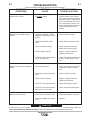
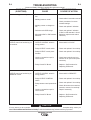
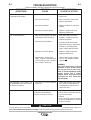
How to Use Troubleshooting Guide.......................................................................E-1
Troubleshooting Guide.............................................................................E-2 thru E-5
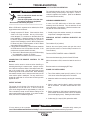
Procedure for Replacing P.C. Boards ............................................................E-6, E-7
––––––––––––––––––––––––––––––––––––––––––––––––––––––––––––––––––––––––
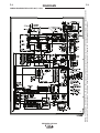
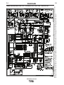
Wiring Diagrams ..............................................................................................Section F
________________________________________________________________________
Parts Pages .................................................................................................P-234, P-239
A-1
A-1
INSTALLATION
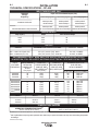
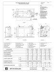
TECHNICAL SPECIFICATIONS – DC-400
INPUT-THREE PHASE ONLY
Input Current at Rated Output (CVI)
Standard
Voltage
Frequency
100% Duty Cycle
60% Duty Cycle
50% Duty Cycle
230/460/575V/60Hz
400Amps/36V
78/39/31Amps
450Amps/38V
83/41/33Amps
500Amps/40V
84/42/34Amps
500Amps/40V
400Amps/36V
450Amps/38V
81/77/47/45/43/41Amps 85/81/49/47/45/42Amps 86/82/50/48/46/43Amps
220/230/380/400/415/440V/50/60Hz
RATED OUTPUT
Volts at Rated Amps
Amps
Duty Cycle (1)
36
38
40
400
450
500
100%
60%
50%
OUTPUT
MAXIMUM OPEN CIRCUIT VOLTAGE
OUTPUT
57V. (CC) 45.5V. (CVI) 60Hz
54V. (CC) 45.5V. (CVI) 50/60 Hz
Min.----60A 12V CV(22V CC)
Max.---500A 42V (CC, CV)
AUXILIARY POWER
115 VAC, 15 AMPS
42 VAC, 10 AMPS
RECOMMENDED INPUT WIRE AND FUSE SIzES FOR MAXIMUM RATED OUTPUT.
IN ADDITION, FOLLOW LATEST NATIONAL ELECTRICAL CODE AND LOCAL CODE.
INPUT AMPERE
INPUT
RATING ON
VOLTAGE /
NAMEPLATE
FREQUENCY
@100%
Duty Cycle
230/60Hz
460/60Hz
575/60Hz
78
39
31
TYPE 75°C
COPPER WIRE IN
CONDUIT AWG
(IEC) SIZES (mm2)
40°C(104°F)
3(25)
8(10)
10(6)
220/50/60Hz
230/50/60Hz
380/50/60Hz
400/50/60Hz
415/50/60Hz
440/50/60Hz
81
77
47
45
43
41
3(25)
3(25)
6(16)
6(16)
8(10)
8(10)
TYPE 75°C
GROUND WIRE IN
CONDUIT AWG
(IEC) SIZES (mm2)
8(10)
8(10)
10(6)
10(6)
10(6)
10(6)
6(16)
10(6)
10(6)
BUSSMANN SUPER LAG
FUSE SIZE AND
CATALOG NUMBER*
FUSE SIZE CATALOG NUMBER
REN-100
100
RES-50
50
RES-40
40
100
100
60
60
60
50
REN-100
REN-100
RES-60
RES-60
RES-60
RES-50
PHYSICAL DIMENSIONS
HEIGHT
WIDTH
DEPTH
27.50 in.
699 mm
22.25 in.
565 mm
32.0 in.
988 mm
WEIGHT
473 lbs.
215 kg.
TEMPERATURE RANGES
OPERATING TEMPERATURE RANGE
-22°F to 104°F(-30°C +40°C)
STORAGE TEMPERATURE RANGE
-40°F to 140°F(-40°C+60°C)
(1) Based upon 10 minute time period (i.e., for 60% duty cycle, it is 6 minutes on an 4 minutes off).
* Use only bussmann Super-Lag fuses specified. Other fuses may not protect the welder and may cause overheating and possible
fire damage.
Insulation class 155(F)
IDEALARC® DC-400
A-2
A-2
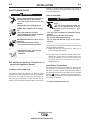
INSTALLATION
Failure to observe these precautions can result in
excessive operating temperatures and nuisance shutdown of the machine.
SAFETY PRECAUTIONS
WARNING
ELECTRIC SHOCK can kill.
• Do not touch electrically live parts or
electrode with skin or wet clothing.
• Insulate yourself from work and
ground.
• Always wear dry insulating gloves.
-----------------------------------------------------------------------FUMES AND GASES can be dangerous.
• Keep your head out of fumes.
• Use ventilation or exhaust to remove
fumes from breathing zone.
-----------------------------------------------------------------------WELDING SPARKS can cause fire or
explosion.
• Keep flammable material away.
• Do not weld on closed containers.
-----------------------------------------------------------------------ARC RAYS can burn eyes and skin.
• Wear eye, ear and body
protection.
-----------------------------------------------------------See additional warning information at
front of this operator’s manual.
----------------------------------------------------------CORRECT OPERATIONAL USE
The machine should be located in a clean dry place
where there is free circulation of clean air such that air
movement in through the front and out through the
back will not be restricted. Dirt and dust that can be
drawn into the machine should be kept to a minimum.
LIMIT ON STACKING
WARNING
FALLING EQUIPMENT can cause
injury.
• Do not lift this machine using lift
bale if it is equipped with a heavy
accessory such as trailer or gas
cylinder.
• Lift only with equipment of adequate lifting
capacity.
• be sure machine is stable when lifting.
• Do not stack more than three high.
• Do not stack the DC-400 on top of any other
machine.
The units may be stacked three high by observing the
following safety precautions:
A. Make sure the first or bottom unit is setting on a
level, well supported surface.
B. The units must be stacked with their fronts flush,
making sure the two holes in the base rails of the
unit being stacked on top are over the two pins
located on the top front corners of the unit it is
being stacked on.
Input Power Connections
By removing the rear access panel the three phase
input power is connected to the three line terminals on
the input contactor, and the earth grounding lead to
the grounding terminal on the input box floor marked
with the
symbol. Install and reconnect panel for
the proper input voltage per the diagram pasted inside
the access panel cover.
See Technical Specification Page:
IDEALARC® DC-400
EARTH GROUND CONNECTION
A-3
A-3
INSTALLATION
REMOTE CONTROL ADAPTER CAbLE (K864)
CAUTION
* Failure to follow these instructions
can cause immediate failure of components within the machine.
• When powering welder from a generator be sure to turn off the welder
first, before generator is shut down in
order to prevent damage to welder.
Output Cable Connections
The output leads are connected to the output terminals marked “+” and “-”. They are located at the lower
right and lower left corners of the front panel.
STRAIGHT PLUG (14 PIN)
TO POWER SOURCE
TO LN-7 WIRE FEEDER
A “V” cable 12” (.30m) long to connect a K857
Remote Control (6 pin connector) with a wire-feeder
(14-pin connector) and the machine (14-pin connector). If a remote control is used alone the wire-feeder
connection is then not used.
WARNING
ELECTRIC SHOCK can kill.
• Turn the power switch of the
welding power source “OFF”
before installing plugs on
cables or when connecting or
disconnecting plugs to welding power source.
MACHINE LOAD
400A
500A
(100% DUTY (50% DUTY
CYCLE)
CYCLE)
3/0
85 mm2
2/0
67 mm2
50 to 100 ft
(15-30 m)
3/0
85 mm2
2/0
67 mm2
100-150 ft
(30-46 m)
3/0
85 mm2
3/0
85 mm2
150-200 ft
(46-61 m)
3/0
85 mm2
3/0
85 mm2
200-250 ft
(67-76 m)
4/0
107 mm2
4/0
107 mm2
1) K857 REMOTE CONTROL
CABLE RECEPTACLE (14 SOCKET)
CAbLE SIzES FOR COMbINED LENGTH OF
ELECTRODE AND WORK CAbLE
UP TO 50 ft
(15m)
TO:
2) K963 HAND AMPTROL
3) K870 FOOT AMPTROL
Output Cables
CAbLE LENGTHS
CABLE RECEPTACLE (6 SOCKET)
AMPTROL ADAPTER CAbLE (843)
INSTALLATION OF FIELD INSTALLED
OPTIONS
A five wire cable, 12” (.30m ) long, used for easy
connection of standard K963 Hand Amptrol or K870
Foot amptrol. The cable has a 6-pin MS-style
connector which connects to the Amptrol and terminals which connect to 75, 76, and 77 on the machine
terminal strip and to the case grounding screw. the
Amptrol will control the same range of output as the
current control on the welder. (if a smaller range of
control is desired for finer adjustment, a K775 Remote
may be used in conjunction with the Amptrol Adapter
Cable Kit.) The Amptrol arc start switch is nonfunctional unless used with a K799 Hi-Frequency Kit.
Remote Output Control (K857 or K857-1
with K864 Adapter)
An optional “remote out control” is available. The
K857 or K857-1 are the same remote control options
that are used on other Lincoln power sources. The
K857 or K857-1 consist of a control box with 25 feet
(7.6 meters) or 100 feet (30.3 meters).
See Amptrol Adapter installation Instructions on next
page.
The K857 and K857-1 have a 6-pin connector and
K857 require a K864 adapter cable which connects to
the 14-pin connector on the case front.
IDEALARC® DC-400
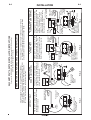
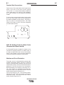
FIG. 1
77
Power source
terminal
strip
K963*, K813* or
K870 Amptrol™
76
Black and white leads
not used. Tape
and insulate.
75
K843
Adapter
POWER
SOURCE
The Amptrol™ provides remote
current control through the full range
of the power source.
AMPTROL™ ONLY
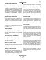
FIG. 2
77
77
76
Bolt and nut
connection.
Insulate
and tape.
K963*, K813* or
K870 Amptrol™
K775 Remote
Limit Control
76
Black and white
leads not used.
Tape and
insulate.
75
K843
Adapter
POWER
SOURCE
The Amptrol™ provides remote
current control from the minimum of
the power source to a maximum set
by the remote limit control.
AMPTROL™ PLUS
REMOTE LIMIT CONTROL
This K843 adapter is used to connect AMPTROL™ (K963*,
K813* or K870), remote control (K775), and HI-FREQ™ (K799)
accessories to DC-250, DC-400, R3R or Weldanpower 250
(D-10 and Pro) with remote control power sources.
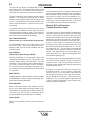
FIG. 3
76
K963*,K813*
or K870
Amptrol™
K843 Adapter
77
CUT OFF
ARC START
SWITCH and connect black
lead to black and white
lead to white.
{
75
Arc start cable
(included with
K799)
K799
Hi-Freq™ Kit
POWER
SOURCE
The Amptrol™ will start the Hi-Freq™
kit to turn on gas and high frequency
starting for DC TIG welding. The
Amptrol™ controls current through
the full range of the power source.
AMPTROL™ AND
HI-FREQ.™ KIT
FIG. 4
CUT OFF
ARC START
SWITCH and
connect black
lead to black and
K799
white lead to white.
{
75
K843
K775
77
76
K963*,K813*
or K870
Amptrol™
K843 Adapter
Bolt and nut
connection.
insulate
and tape.
76
77
POWER
SOURCE
Arc start cable
(included
with K799)
K799
Hi-Freq™
Kit
K775 Remote
Limit Control
The Amptrol™ switch will start the
Hi-Freq™ kit to turn on gas and high
frequency starting for DC TIG
welding. The Amptrol™ controls
current from the minimum of the
power source to a maximum set by
the remote limit control.
AMPTROL™ AND HI-FREQ.™ KIT
PLUS REMOTE LIMIT CONTROL
The power source "machine/remote" switch must be in "remote"
for Amptrol™ to control current. Accessories may be combined
and connected in four different ways, as shown below.
WARNING: TURN THE POWER SOURCE OFF BEFORE INSTALLATION
For use with: DC-250, DC-400, R3R or Weldanpower 250 (D-10 and Pro)
with remote control power sources.
K843 AMPTROL™ ADAPTER INSTALLATION INSTRUCTIONS
A-4
INSTALLATION
A-4
67
77
{
997K
elbac trats crA
dedulcni(
)997K htiw
FFO TUC
TRATS CRA
dna HCTIWS
kcalb tcennoc
dna kcalb ot dael
.etihw ot dael etihw
57
REWOP ™qerF-iH
tiK
ECRUOS
4 .GIF
348K 997K
577K
)orP dna 01-D( 052 rewopnadleW ro R3R ,004-CD ,052-CD :htiw esu roF
.secruos rewop lortnoc etomer htiw
SNOITCURTSNI NOITALLATSNI RETPADA ™LORTPMA 348K
DNA ™LORTPMA
TIK ™.QERF-IH
67
3 .GIF
997K
tiK ™qerF-iH
{
elbac trats crA
htiw dedulcni(
)997K
57
FFO TUC
TRATS CRA
kcalb tcennoc dna HCTIWS
etihw dna kcalb ot dael
.etihw ot dael
77
retpadA 348K
REWOP
ECRUOS
™qerF-iH eht trats lliw ™lortpmA ehT
ycneuqerf hgih dna sag no nrut ot tik
ehT .gnidlew GIT CD rof gnitrats
hguorht tnerruc slortnoc ™lortpmA
.ecruos rewop eht fo egnar lluf eht
*318K,*369K
078K ro
™lortpmA
67
77
tun dna tloB
.noitcennoc
etalusnI
.epat dna
77
2 .GIF
REWOP
ECRUOS
348K
retpadA
57
etihw dna kcalB
.desu ton sdael
dna epaT
.etalusni
67
etomeR 577K
lortnoC timiL
etomer sedivorp ™lortpmA ehT
fo muminim eht morf lortnoc tnerruc
tes mumixam a ot ecruos rewop eht
.lortnoc timil etomer eht yb
ro *318K ,*369K
™lortpmA 078K
SULP ™LORTPMA
LORTNOC TIMIL ETOMER
67
1 .GIF
REWOP
ECRUOS
348K
retpadA
57
sdael etihw dna kcalB
epaT .desu ton
.etalusni dna
77
ecruos rewoP
lanimret
pirts
ro *318K ,*369K
™lortpmA 078K
etomer sedivorp ™lortpmA ehT
egnar lluf eht hguorht lortnoc tnerruc
.ecruos rewop eht fo
YLNO ™LORTPMA
,*369K( ™LORTPMA tcennoc ot desu si retpada 348K sihT
)997K( ™QERF-IH dna ,)577K( lortnoc etomer ,)078K ro *318K
052 rewopnadleW ro R3R ,004-CD ,052-CD ot seirossecca
.secruos rewop lortnoc etomer htiw )orP dna 01-D(
NOITALLATSNI EROFEB FFO ECRUOS REWOP EHT NRUT :GNINRAW
"etomer" ni eb tsum hctiws "etomer/enihcam" ecruos rewop ehT
denibmoc eb yam seirosseccA .tnerruc lortnoc ot ™lortpmA rof
.woleb nwohs sa ,syaw tnereffid ruof ni detcennoc dna
eht trats lliw hctiws ™lortpmA ehT
hgih dna sag no nrut ot tik ™qerF-iH
GIT CD rof gnitrats ycneuqerf
slortnoc ™lortpmA ehT .gnidlew
eht fo muminim eht morf tnerruc
yb tes mumixam a ot ecruos rewop
.lortnoc timil etomer eht
TIK ™.QERF-IH DNA ™LORTPMA
LORTNOC TIMIL ETOMER SULP
*318K,*369K
078K ro
™lortpmA
etomeR 577K
lortnoC timiL
retpadA 348K
tun dna tloB
.noitcennoc
etalusni
.epat dna 77 67
A-5
INSTALLATION
A-5
INSTALLATION
OF
EQUIPMENT
REQUIRED
FOR
RECOMMENDED
PROCESSES
MULTIPROCESS SWITCH CONNECTION AND
OPERATION
WIRE FEEDER CONTROL CAbLE CONNECTIONS
A Multiprocess Switch has been designed for use with
the DC-400 or DC-600. With this switch installed on
the DC-400, it permits easy changing of the polarity of
the wire feed unit connected and also provides separate terminals for connection of stick or air carbon arc.
The Multiprocess Switch is available as either a factory installed or field installed option.
For control cable with 14-pin connector:
Connect control cable to 14-pin connector on the front
panel of the machine. See the appropriate connection
diagram for the exact instructions for the wire feeder
being used. Refer to Section 2.4.1 for connector pin
functions.
For control cable with terminal strip connectors:
The control cable from the wire feeding equipment is
connected to the terminal strips behind the control
panel*. A strain relief box connector is provided for
access into the terminal strip section. A chassis
ground screw is also provided below the terminal strip
marked with the symbol
for connecting the automatic equipment grounding wire. See the appropriate
connection diagram for the exact instructions for the
wire feeder being used.
A cover (Lincoln Electric Part Number S17062-3) is
available for the unused 14-pin connector to protect it
against dirt and moisture.
* See Terminal Strip Connections section for access
to the terminal strips.
CONNECTION OF DC-400 TO LN-22 OR LN-25
PURPOSE
NOTE: IF THE DC-400 IS TO BE USED FOR BOTH
SEMIAUTOMATIC/AUTOMATIC AND STICK/
AIR CARBON ARC, THEN A MULTIPROCESS SWITCH IS REQUIRED.
DESIGN
The Multiprocess Switch consists of a 3-position
switch assembly that is mounted in a sheet metal
enclosure that has two output terminals on each end
of the box. The two terminals on the left side of the
box are for connection of wire feed electrode and work
leads. The two terminals on the right side of the box
are for connection of work and electrode for stick or
air carbon arc. The output terminals are protected
against accidental contact by hinged covers.
The switch mounts to the front of the DC-400 by
means of a bracket that fastens to the case sides.
Two 4/0 (107 mm2) leads connect the switch assembly to each output stud.
a) Turn off all power.
CONNECTIONS
b) Place output terminals switch into the “ON” position.
1. Connect wire feed unit electrode and work cables
through the rectangular strain relief holes in the
base of the DC-400 to the output studs on the left
side of the box.
c) Connect the electrode cable to the output terminal
of polarity required by electrode. Connect the work
lead to the other terminal.
d) Place the OUTPUT CONTROL Switch at “LOCAL”
position unless a Remote Control is connected to
the DC-400.
e) Place MODE SWITCH in “CONSTANT VOLTAGE
(FCAW, GMAW)”.
NOTE: The output terminals are energized at all
times.
2. Connect wire feeder control cable and make other
terminal strip connections as specified on the connection diagram for the Lincoln wire feeder being
used. “Electrode” and “Work” are connected to the
left side of the Multiprocess Switch.
3. Connect stick or air carbon arc electrode and work
cables through the rectangular strain relief holes in
the base of the DC-400 to the output studs on the
right side of the box.
OPERATION
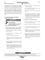
IDEALARC® DC-400
A-6
A-6
INSTALLATION
MULTIPROCESS SWITCH
equipment
auto
auto or
To semi-
jumper
4/0 (107 mm2 )
User supplied
ELECTRODE
WORK
+
arc torch
air carbon
holder or
electrode
To stick
The operation of the switch is as follows:
WORK
+
To stick
electrode
holder or
air carbon
arc torch
A semiautomatic or automatic wire feed unit electrode
and work cables are connected to the terminals on the To semiELECTRODE
left side of the box. Stick or air carbon arc electrode
auto or
auto
and work leads are connected to the terminals on the
User supplied
right side of the box. There are three positions on the equipment
4/0 (107 mm 2 )
jumper
switch. With the switch in the left position, the wire
feed terminals are electrode negative. In the center
position, the wire feeder terminals are electrode posiMULTIPROCESS SWITCH
tive. In both the left and center switch position, the
right side stick terminals are disconnected. In the
To change stick polarity, reverse the leads at the (+)
right switch position, the wire feed terminals are disand (-) terminals on the right side of the Multiprocess
connected from the DC-400 and the stick terminals
Switch.
connected. The polarity of the stick terminals is
marked on the end of the box. To change polarity, the
NOTE: When a DC-400 equipped with Multiprocess
electrode and work leads must be interchanged. In
Switch is mounted on an undercarriage, the
the stick position, the stick terminals are energized at
undercarriage handle in the resting position
all times.
can hit the case of the Multiprocess Switch.
This does no harm, but if the user desires, a
1/4” or 3/8” bolt and nut may be placed in the
CONNECTIONS
hole in the undercarriage tow bar to limit the
travel of the undercarriage handle.
(For those applications where it is not necessary to
have separate work cables for stick and semiautomatic welding.)
STICK, TIG OR AIR/CARbON ARC *
If both stick and semiautomatic welding is done on the
same workpiece, only one work lead is required. To
do this, connect a 4/0 (107 mm2) jumper from the
work terminal on the semiautomatic side to the terminal to be used for work on the stick side. The work
lead from the semiautomatic side then serves as the
work lead for both semiautomatic and stick welding.
a) Turn off all power.
b) Disconnect all wire feed unit control, electrode, and
work leads.
c) Place MODE SWITCH in the “CONSTANT CURRENT (STICK/TIG)” for air carbon arc.
d) For stick, TIG or air carbon arc, place OUTPUT
TERMINALS switch into the “ON” position. With
the DC-400 connected for stick, TIG or air carbon
arc welding, the output terminals will be energized
at all times.
*NOTE: If stick welding, TIG welding or air carbon arc
cutting is to be done on the DC-400 along
with semi-automatic/automatic welding, then
a K804-1 Multiprocess Switch is required. If
the Multiprocess Switch is not used, then all
control, electrode, and work leads to wire
feed equipment must be disconnected from
the DC-400 before connecting the DC-400 for
stick or air carbon arc cutting.
IDEALARC® DC-400
b-1
b-1
OPERATION
SAFETY PRECAUTIONS
OUTPUT CONTROL DIAL
WARNING
Output (Control)
ELECTRIC SHOCK can kill.
• Have an electrician install and service this equipment.
• Turn the input power off at the fuse
box before working on equipment.
• Do not touch electrically hot parts.
• This next section applies to DC-400’s without
the Capacitor Discharge Option:
When using a DC-400 power source with wire feeders
which do not have an electrical trigger interlock (or
with wire feeders with the electrical trigger interlock in
the OFF position), there will be a small spark if the
electrode contacts the work or ground within several
seconds after releasing the trigger.
Increase/Decrease of
Output
(Voltage or
Current)
OUTPUT CONTROL “LOCAL-REMOTE” SWITCH
Remote Output Voltage
or Current Control
When used with some wire feeders with the electrical
trigger interlock in the ON position, the arc can restart
if the electrode touches the work or ground during
these several seconds.
Local Output Voltage or
Current Control
CIRCUIT bREAKER
WARNING
• Be sure to select OUTPUT TERMINALS “REMOTE
ON/OFF” for operation with wire feeders that have
leads numbered 2 and 4.
Circuit breaker
THERMAL PROTECTION LIGHT
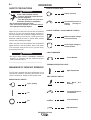
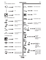
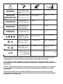
MEANINGS OF GRAPHIC SYMbOLS
High Temperature
The DC-400 nameplate has been redesigned to use
international symbols in describing the function of the
various components. Below are the symbols used.
ARC CONTROL SWITCH
POWER ON-OFF SWITCH
Input (Power)
Gas Metal
Welding
On
Increase/Decrease
of Inductance
Low Inductance
Off
High Inductance
IDEALARC® DC-400
Arc
b-2
b-2
OPERATION
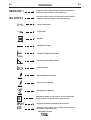
OUTPUT TERMINALS SWITCH
RATING PLATE
Output (Voltage)
Three Phase Power
On
Transformer
Remote On/Off
Rectifier
ARC FORCE CONTROL DIAL
Rectified DC Output
Shielded Metal Arc
Welding
Constant Voltage
Characteristic
Gas Tungsten Arc
Welding
MODE SWITCH
Arc Force Current
Do not switch if
output voltage
or current is
present.
Increase/Decrease
of Current
Constant
Voltage
(Submerged Arc
Welding)
VOLTMETER SWITCH
Voltmeter
Positive Electrode
Negative Electrode
EARTH GROUND CONNECTION
Signifying the Earth
(Ground) Connection
IDEALARC® DC-400
Constant
Voltage (Flux
cored arc
weldin,gas
metal arc welding).
C o n s t a n t
Current (shield
metal arc welding, gas tungsten arc welding).
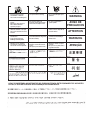
b-3
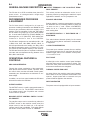
OPERATION
RATING PLATE
(Continued)
NEMA EW 1
Designates welder complies with National Electrical Manufacturers
Association requirements EW 1. (Export Model only)
IEC 60974-1
Designates welder complies with International Electrotechnical
Commission requirements 60974-1. (European model only)
Three Phase Power
Transformer
Rectifier
Rectified DC Output
Constant Voltage Characteristic
Constant Current Characteristic
Line Connection
Shielded Metal Arc Welding
Flux Cored Arc Welding
Submerged Arc Welding
S
IP21
CE
Designates Welder can be used in environments with
increased hazard of electric shock. (IEC model only)
Degree of protection provided by the enclosure
Designates welder complies with low voltage directive and with
EMC directive. (Export Model only)
IDEALARC® DC-400
b-3
b-4
OPERATION
b-4
GENERAL MACHINE DESCRIPTION
OUTPUT TERMINALS “ON” OR OUTPUT TERMINALS “REMOTE”
The DC-400 is an SCR controlled three phase DC
power source. It is designed with a single range
potentiometer control.
This switch provides an alternative to the “2 to 4”
jumpering function by energizing the machine’s output
regardless of whether “2 or 4” is jumpered or not.
RECOMMENDED PROCESSES
& EQUIPMENT
POLARITY SELECTION
The DC-400 model is designed for all open arc
processes including Innershield® and GMAW all solid
wire and gas procedures within the capacity of the
machine, plus the capability of stick and TIG welding
and air carbon arc gouging up to 5/16” (8mm) diameter. A mode switch selects CV (FCAW, GMAW), CV
Submerged Arc, or CC (Stick/TIG). Stick welding performance is similar to that of the R3R-500.
The DC-400 is designed to be used with the LN-7, LN7 GMA, LN-8, LN-9, LN-9 GMA, LN-23P, LN-25, or
LN-742 semiautomatic wire feeders, the NA-3, NA-5
and NA-5R automatics, and the LT-56 and LT-7 tractors, within the 400 ampere capacity of the machine.
The DC-400 Diode Kit option is required to utilize the
cold start and cold electrode sensing features of the
NA-3, NA-5 and NA-5R.
Polarity selection is made by appropriately connecting
the electrode and work welding cables to either the
“ + “ stud or to the “- ” stud. Select “VOLTMETER”
switch for “+” or “-” electrode, for the remote (#21)
work sensing lead.
VOLTMETER SWITCH “+” ELECTRODE OR “-”
ELECTRODE
This switch selects electrode polarity for the remote
(#21) work sensing lead of automatic or semiautomatic equipment.
115 VOLT POWER SWITCH
The power input contactor operates from an auxiliary
115 volt transformer that is energized through the
POWER toggle switch on the machine control panel.
“ I “ is on and “0” is off.
PILOT LIGHT
OPERATIONAL FEATURES &
CONTROLS
A white light on the machine control panel indicates
when the power source input contactor is closed. This
means the main power transformer and all auxiliary
and control transformers are energized.
ARC CHARACTERISTICS
Through the unique combination of the transformer,
three phase semiconverter rectifier, capacitor bank,
arc control choke, and the solid state control system,
outstanding arc characteristics are achieved on constant voltage.
In addition, an arc force control enables the DC-400 to
stick weld as well as the R3R-500.
OUTPUT CONTROL
THERMAL PROTECTION LIGHT
An amber light on the machine control panel indicates
when either of the two protective thermostats have
opened. Output power will be removed but input
power will still be applied to the machine.
INPUT CONTACTOR
The power source is equipped with an input contactor.
The OUTPUT control, a small 2 watt potentiometer, is
calibrated from 1 to 10. The OUTPUT control serves
as a voltage control in the CV position and a current
control in the CC position.
MACHINE OUTPUT CONTROL SWITCH “LOCAL”
OR “REMOTE”
The machine output can be controlled by either the
OUTPUT control on the machine control panel, the
output control on the wire feed unit, or an optional
“remote control” that is available. This switch selects
the mode of control, either “LOCAL” or “REMOTE”.
IDEALARC® DC-400
b-5
OPERATION
POWER SOURCE OPERATION AND
CONTROLS
WARNING
ELECTRIC SHOCK can kill.
• Have an electrician install and service this equipment.
• Turn the input power off at the fuse
box before working on equipment.
• Do not touch electrically hot parts.
Duty Cycle and Time Period
The DC-400 is rated at the following duty cycles:
DUTY CYCLE *
AMPS
VOLTS
100%
60%
50%
400
450
500
36
38
40
* Based upon 10 minute time period (i.e., for 60% duty
cycle, it is 6 minutes on and 4 minutes off).
Overloading the DC-400 may result in opening of an
internal protective thermostat as indicated by the
amber thermal protection light turning on.
STARTING THE MACHINE
The POWER toggle switch at the extreme right side of
the control panel in the “I“ position energizes and closes the three phase input contactor from a 115 volt
auxiliary transformer. This in turn energizes the main
power transformer.
The machine is de-energized when the POWER
switch is in the “0” position.
The white light below the POWER switch indicates
when the input contactor is energized.
OUTPUT CONTROL DIAL
The OUTPUT control to the right of the center of the
control panel is a continuous control of the machine
output. The control may be rotated from minimum to
maximum while under load to adjust the machine output.
The machine is equipped with line voltage compensation as a standard feature. This will hold the output
constant except at maximum output of the machine,
through a fluctuation of ±10% input line voltage.
b-5
OUTPUT CONTROL “LOCAL-REMOTE” SWITCH©
The OUTPUT CONTROL toggle switch on the control
panel labeled “LOCAL-REMOTE” gives the operator
the option of controlling the output at the machine
control panel or at a remote station. For remote control, the toggle switch is set in the “REMOTE” position
and controlled at the wire feed unit control, or by connecting a K775 control to terminals 75, 76, and 77 on
the terminal strip at the front of the machine, or by
connecting a K857 control to the 14-pin connector on
the front of the machine. For control at the machine
control panel, the toggle switch is set in the “LOCAL”.
(Exception: When used with an LN-9, LN-9 GMA or
NA-5 wire feeder, the OUTPUT CONTROL switch
must be in the “REMOTE” position or automatic shutdown of the LN-9 or NA-5 may occur.)
POLARITY SELECTION
Polarity selection is made by appropriately connecting
the electrode and work welding cables to either the
“ + ” stud or to the “- ” stud. Select “VOLTMETER”
switch for “+” or “-” electrode for the remote (#21)
work sensing lead.
VOLTMETER SWITCH
Select “+” for positive electrode or “-” for negative
electrode polarity for the remote (#21) work sensing
lead of automatic or semiautomatic equipment.
THERMAL PROTECTION LIGHT
The amber thermal protection light will be lit if either of
the two protective thermostats have opened. The output power will be disabled but input power will still be
applied to the welder. (Refer to Machine and Circuit
Protection section).
MODE SWITCH
The large MODE SWITCH on the left side of the
machine, labeled “Constant Voltage (Submerged Arc),
Constant Voltage (FCAW/GMAW) and Constant
Current (Stick/TIG)”, is used to select the proper
welder characteristics for the process being used.
The CV (FCAW/GMAW) Mode permits the DC-400 to
produce essentially a flat output characteristic that can
be varied from approx. 12 to 42 volts.
IDEALARC® DC-400
b-6
b-6
OPERATION
In this position, the dynamic characteristics of the
machine under welding conditions provide optimum
welding characteristics for Innershield® welding, other
open arc processes including short arc MIG welding,
and air carbon arc. Most submerged arc welding can
also be done in this mode.
The CV (Submerged Arc) Mode also produces an
essentially flat output characteristic that can be varied
from approximately 12 to 42 volts. The dynamic
characteristics of the CV Submerged Arc Mode make
possible improved submerged arc welding over that
possible using the Constant Voltage Innershield
Mode. The improvement is most noticeable on high
deposition, slow travel speed welds.
There are no means provided to switch between any
of the modes remotely. Do not change the position of
the MODE SWITCH if output voltage or current is present as this may damage the switch.
The CC Mode permits the DC-400 to produce a constant current output characteristic through the range of
60-500 amps with an open circuit voltage of approximately 57 volts (54V on 50/60 Hz). Stick welding and
TIG are done with this position of the Mode Switch.
ARC FORCE CONTROL DIAL (Effective only in CC
mode)
The ARC FORCE control is calibrated from one to ten.
For most welding, the dial should be set at approximately midrange, 5-6. Adjustments up or down can
then be made depending on the electrode, procedures, and operator preference. Lower settings will
provide less short circuit current and a softer arc. A
setting that is too low may cause the electrode to stick
in the puddle. Higher settings will provide a higher
short circuit current and a more forceful arc.
Excessive spatter may result if the control setting is
too high. For most TIG welding applications adjust
this control to a minimum for best operating characteristics.
OUTPUT TERMINALS SWITCH
The OUTPUT TERMINALS toggle switch on the control panel labeled “REMOTE - ON” allows the welder
output to be activated remotely or to be always on.
For remote operation, the toggle switch is set in
“REMOTE” position and the welder output will be activated when 2 and 4 are closed when using a wirefeeder. For welder output to always be activated, set
the switch to the “ON” position.
110-115V AC and 40-42V AC Auxiliary
Power and Control Connections
14-PIN CONNECTOR
The 14-pin connector receptacle supplies auxiliary
power.
40-42V AC is available at receptacle pins I and K. A
10 amp circuit breaker protects this circuit.
On the Domestic and Export models 110-115V AC is
available at receptacle pins A and J. A 10 amp circuit
breaker protects this circuit. Note that the 40-42V AC
and 110-115V AC circuits are electrically isolated from
each other.
FRONT VIEW OF 14-PIN
CONNECTOR RECEPTACLE
M =SPARE
=77
K=42
F = 7 6G
=75
D = 4E
H=21
C=2
L=SPARE
N=SPARE
B=GND
A=32
I=41
K=42
J=31
A=32
J=31
I=41
B=GND
N=SPARE
L=SPARE
C=2
H=21
D=4
G=75
E=77
M =SPARE
F=76
ARC CONTROL SWITCH (Effective only in CV
FCAW/GMAW mode)
The ARC CONTROL is a tapped switch numbered
from 1 to 5 and changes the pinch effect of the arc.
This control is most useful in processes that utilize a
“shorting” metal transfer and controls the spatter, fluidity, and bead shape. The pinch effect is increased by
turning the control clockwise.
For all applications, a good starting point for the ARC
CONTROL is a midrange dial setting of 3. The control
can be increased or decreased as desired.
PIN
LEAD NO.
A
B
C
D
E
F
G
H
I
J
K
L
M
N
32
GND
2
4
77
76
75
21
41
31
42
-------
IDEALARC® DC-400
FUNCTION
110 - 115V AC (Domestic & Export)
CHASSIS CONNECTION
TRIGGER CIRCUIT
TRIGGER CIRCUIT
OUTPUT CONTROL
OUTPUT CONTROL
OUTPUT CONTROL
WORK CONNECTION
40-42V AC
110-115V AC (Domestic & Export)
40-42V AC
-------
b-7
OPERATION
Terminal Strip Connections
Terminal strip TS2 located behind the hinged control
panel on the front of the power source supplies
110-115V AC. A 10 amp circuit breaker protects this
circuit. Note that this 110-115V AC is also available in
the 14-pin connector on the Domestic and Export
models.
To gain access to the terminal strips simply remote
the six #10 sheet metal screws from the perimeter of
the welder nameplate as shown below. Tilt panel forward so it rests in a horizontal position. See Table
showing Front View of 14-Pin Connector Receptacle
for lead number functions.
5
4
1
3
6
1
2
2
6
5
4
3
230V AC Auxiliary Power for Water Cooler
(European and Export models)
A Continental European receptacle is located on the
rear panel for supplying 230V AC to a water cooler. A
3.5 amps, (2 amps below code 11277) circuit breaker
which is also located on the rear panel protects this
circuit from excessive overloads or short circuits.
Machine and Circuit Protection
The power source is thermostatically protected with
proximity thermostats against overload or insufficient
cooling. One thermostat is located on the nose of the
center bottom primary coil and a second thermostat is
attached to the lead connection the secondaries.
Both thermostats are connected in series with 2-4 circuit. If the machine is overloaded, the primary thermostat will open, the output will be zero, and the
amber thermal protection light will be on.
The fan will continue to run. The secondary thermostat will open either with an excessive overload or
insufficient cooling. The output will be zero and the
amber protection light will be off.
IDEALARC® DC-400
b-7
b-8
OPERATION
b-8
AUXILIARY POWER CONNECTIONS
The power source is equipped to furnish nominally
110-115 volt AC and 40-42 volt AC auxiliary power for
operating wire feeding equipment, etc. The auxiliary
power is available at the 14-pin MS-style connector
receptacle on the control panel and/or at a terminal
strip behind the hinged control panel on the front of
the power source. 110-115V AC is available at receptacle pins A and J (Domestic and Export models only),
and terminals 31 and 32 (all models). 40-42V AC is
available only at receptacle pins I and K. The 110115V AC and the 40-42V AC are isolated circuits and
each is protected by a 10 amp circuit breaker.
The SCR snubber board consists of a capacitor and
resistor connected across each SCR and across the
entire bridge and MOV’s to protect the control circuitry
and SCR’s from transient voltages. The snubber
board is mounted on the back of the case front.
The SCR firing circuit, the control fault protection circuit, the power-up delay circuit, and the power circuit
are mounted on the control PC board located behind
the front control panel. (The front control panel hinges
down for easy access to the board.)
The starting circuit board is located on the back of the
control box.
REMOTE CONTROL CONNECTIONS
MACHINE COOLING
Remote control connections are available both at a
14-pin connector receptacle located on the control
panel, and on terminal strips with screw connections
located behind the hinged control panel on the front of
the power source.
The fan pulls air in through the louvered front of the
machine over the internal parts and exhausts out the
louvered rear of the machine. The fan motor is fully
enclosed, has sealed ball bearings, requires no lubrication, and operates when the power switch is turned
on.
OUTPUT CONNECTIONS
CASE FEATURES
The output terminals are recessed on the case front
and labeled “+” and “-”.
INPUT CONNECTIONS
The three input lines are brought in through the rear
panel of the power source and attached to the input
contactor. Removal of the removable access panel
makes the contactor accessible for the input cable
connections.
INPUT LINE VOLTAGE COMPENSATION
The power source is equipped with input line voltage
compensation as standard. For a line voltage fluctuation of ±10% the output will remain essentially constant. This is accomplished through the feedback network in the control circuit.
SOLID STATE OUTPUT CONTROL
The output of the welder is electronically controlled by
SCR’s instead of mechanical contactors, providing
extra long life for highly repetitive welding applications.
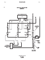
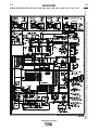
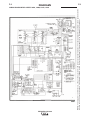
SOLID STATE CONTROL SYSTEM
The control circuitry consists of six basic circuits: (1)
the SCR snubber network, (2) the SCR firing circuit,
(3) the control/fault protection circuit, (4) the starting
circuit, (5) the power-up delay circuit, and (6) the
power circuit.
The machine uses a 32” (813mm) long base. The low
profile case facilitates installation of the machine
under a workbench and stacking the machines three
high to conserve floor space.
The case front incorporates a recessed control panel
where all the machine controls are mounted. This
recessed panel protects the controls and minimizes
the possibilities of accidental contact. This control
panel can be easily opened to permit access to the
enclosed control section which contains the terminal
strips, PC board, etc.
The output lead terminals are also recessed to avoid
any object or person accidentally coming in contact
with an output terminal. Strain relief is provided by
holes in the front of the base. The leads are routed up
through these holes to the output terminals. This prevents any damage of the output studs or insulation of
same in the event the cables are pulled excessively.
An output stud cover protects against accidental contact with the output studs. Cover hinges upward for
access to the studs.
The individual case sides are removable for easy
access for internal service or inspection. These are
removable even though the machines are stacked
three high.
IDEALARC® DC-400
b-9
OPERATION
The case rear, top section, is equipped with a removable access panel. This provides easy access to the
input contactor, easy connection and reconnection of
input leads, and easy access for service or inspection.
The total construction of the machine permits outdoor
operation. The enclosure is designed with air intake
louvers that keep dripping water from being drawn into
the unit. The transformer, SCR bridge assembly, and
choke are double-dipped in a special corrosion resistant coating.
A permanent lifting hook is located at the top of the
machine and is positioned so that it acts as nearly as
possible through the center of gravity. This lift hook is
so positioned that it fits without interference under the
base of the second machine when stacking.
ARC FORCE SELECTOR
(Effective only on CC for Stick and TIG Processes)
An ARC FORCE selector is provided similar to that
used on the R3R. This control allows the user to
select the ideal arc force for the procedure and electrode being used.
ARC CONTROL
(Effective Only When Using CVI Mode)
The ARC CONTROL is a five-position switch that
changes the pinch effect of the arc. This results in the
control of spatter, fluidity, and bead shape. The ARC
CONTROL is set to provide optimum welding depending on the process being used, position, electrode,
etc. The pinch effect is increased by turning the control clockwise and may be adjusted while the machine
is in operation.
MODE SWITCH
A MODE SWITCH selects between Constant Voltage
(FCAW/GMAW), Constant Voltage (Submerged Arc),
and Constant Current (Stick/TIG).
b-9
DIODE OPTION
The DC-400 Diode option is required to utilize the cold
start and cold electrode sensing features of the NA-3,
NA-5 or NA-5R. When this option is not used with an
NA-3, NA-5 or NA-5R, see the DC-400/NA-3, DC400/NA-5 or DC-400/NA-5R connection diagram for
instructions on how to disable this circuit. If the circuit
is not disabled, the wire cannot be inched down.
Machine & Circuit Protection
(Thermal Protection Light)
The power source is thermostatically protected with
proximity thermostats against overload or insufficient
cooling. One thermostat is located on the nose of the
center bottom primary coil and a second thermostat is
attached to the lead connecting the secondaries.
Both thermostats are connected in a series with the 24 circuit. If the machine is overloaded, the primary
thermostat will be open, the output will be zero, and
the amber thermal protection light will be on. The fan
will continue to run. The secondary thermostat will
open either with an excessive overload or insufficient
cooling. The output will be zero and the amber protection light will be on. When the thermostats reset
the protection light will be off.
The power source is also protected against overloads
on the SCR bridge assembly through an electronic
protection circuit. This circuit senses an overload on
the power source and limits the output to 550 amps by
phasing back the SCR’s.
Protection is provided to protect the circuitry from
accidental grounds. If the customer accidentally
“grounds” 75, 76, or 77 to the positive output lead, the
DC-400 will be reduced to a low value, thus preventing any damage to the machine. If the ground occurs
between 75, 76, 77 and the negative output lead, one
of the PC board “self-restoring” fuses will blow, preventing any machine damage.
STICK WELDING
When the DC-400 is used for stick welding or air carbon arc, the control leads and welding cables to any
semiautomatic or automatic wire feeders must be disconnected from the DC-400 for maximum safety
(unless the Multiprocess switch option is installed).
PARALLELING
There are no provisions on the DC-400 to permit paralleling.
IDEALARC® DC-400
C-1
ACCESSORIES
C-1
TIG OPTIONS
UNDERCARRIAGES (K817, K817R, K841)
TIG MODULE (K930-2)
For easy moving of the machine, optional undercarriages are available with either steel (K817) or rubber
tired (K817R) wheels or a platform undercarriage
(K841) with mountings for two gas cylinder at rear of
welder.
Docking Kit
Control Cable Extension-45’
Water valve Kit
AMPTROL ADAPTER FOR K799 HI-FREQUENCY
KIT (K915-1, REQUIRES K864 ADAPTER)
Install per instructions provided with trailer.
A “V” cable to connect a K799 Hi-Freq Kit (5-pin connector) with either a K963 Hand Amptrol or a K870
Foot Amptrol (6-pin connector) and the machine. The
cable going to the machine has a 6-pin connector
which requires a K864 adapter to connect with the 14pin connector on the DC-400. Refer to S20909
instructions for connection information.
Factory Installed Options
MULTIPROCESS SWITCH (K804-1)
OPTIONAL EQUIPMENT
DIODE OPTION
This internally installed option allows the use of the
cold start and cold electrode sensing features of the
NA-3, NA-5 or NA-5R.
MULTIPROCESS SWITCH
Kit that mounts on the front of the DC-400, and
includes hinged covers over its output studs. The
switch
has
three
positions:
Positive
semiautomatic/automatic, negative semiautomatic/
automatic, and stick/air carbon arc. Required when
using the DC-400 for both semiautomatic/automatic
and stick/air carbon arc.
Install per M17137 instructions included with the field
installed kit.
CAPACITOR DISCHARGE CIRCUIT (K828-1)
Circuit that mounts inside the DC-400.
Recommended when:
Factory or field installed kit that mounts on the front of
the DC-400, and includes hinged covers over its output studs. The switch has three positions: Positive
semiautomatic / automatic, negative semiautomatic /
automatic, and stick / air carbon arc. Required when
using the DC-400 for both semiautomatic/automatic
and stick/air carbon arc. The field installed kit equivalent is identified as K804-1. For details on the
Multiprocess Switch, see the Installation of Equipment
section.
Field Installed Options
REMOTE OUTPUT CONTROL
(K857 WITH K864 ADAPTER OR K775 )
1) DC-400 is used in conjunction with any LN-23P or
older LN-8 or LN-9 semiautomatic wire-feeder.
Eliminates possible arc flash re-start of weld when
trigger interlock is used. Not required with current
LN-8 (above Code 8700), or LN-9’s with serial numbers above 115187 (manufactured after 12/83), or
any LN-9 having an L6043-1 Power PC Board.
2) DC-400 is used with an LN-22 equipped with an
older K279 Contactor-Voltage Control Option.
Eliminates electrode overrun when gun trigger is
released. Not required when later K279 (above
Code 8800) is used.
3) DC-400 is used with any semiautomatic wire-feeder
and possible small spark, if electrode touches work
just after gun trigger is released, is objectionable.
Install per M17060 instructions included with the
Kit.
The K857 has a 6-pin MS-style connector. The K857
requires a K864 adapter cable which connects to the
14-pin connector on the machine.
An optional “remote output control” is available. This is
the same remote control that is used on the Lincoln
R3R, and DC-600 power sources (K775). The K775
consists of a control box with 28 ft (8.5m) of four conductor cable. This connects to terminals 75, 76, and
77 on the terminal strip and the case grounding screw
so marked with the symbol
on the machine. These
terminals are located behind the control panel on the
front of the power source. This control will give the
same control as the output control on the machine.
IDEALARC® DC-400
C-2
ACCESSORIES
C-2
AMPTROL™ ADAPTER CAbLE (K843)
TO LN-7 WIRE FEEDER
CABLE RECEPTACLE (14 SOCKET)
3) K870 FOOT AMPTROL
2) K963 HAND AMPTROL
TO POWER SOURCE
STRAIGHT PLUG (14 PIN)
TO: 1) K857 REMOTE CONTROL
CABLE RECEPTACLE (6 SOCKET)
A five wire cable, 12” (.30m) long, is available for easy
connection of standard K963 Hand Amptrol or K870
Foot Amptrol. The cable has a 6-pin MS-style connector which connects to the Amptrol and terminals which
connect to 75, 76 and 77 on the machine terminal
strip and to the case grounding screw. The Amptrol
will control the same range of output as the current
control on the welder. (If a smaller range of control is
desired for finer adjustment, a K775 Remote may be
used in conjunction with the Amptrol Adapter Cable
Kit. Connection information is included with the
Amptrol Adapter Cable Kit.) The Amptrol arc start
switch is nonfunctional in this application.
For easy moving of the machine, optional undercarriages are available with either steel (K817) or rubber
tired (K817R) wheels or a platform undercarriage
(K841) with mountings for two gas cylinder at rear of
welder.
Install per instructions provided with trailer.
REMOTE CONTROL ADAPTER CAbLE (K864)
STRAIGHT PLUG (14 PIN)
TO POWER SOURCE
CABLE RECEPTACLE (6 SOCKET)
TO:
1) K857 REMOTE CONTROL
2) K963 HAND AMPTROL
3) K870 FOOT AMPTROL
CABLE RECEPTACLE (14 SOCKET)
TO LN-7 WIRE FEEDER
A “V” cable 12” (.30m) long to connect a K857
Remote Control, K963 Hand Amptrol or K870 Foot
Amptrol (6-pin connector) with a wire-feeder (14-pin
connector) and the machine (14-pin connector). If a
remote control or amptrol is used alone the wire-feeder connection is then not used.
MULTIPROCESS SWITCH (K804-1)
Field installed kit that mounts on the front of the DC400, and includes hinged covers over its output studs.
The switch has three positions: Positive semiautomatic / automatic, negative semiautomatic / automatic,
and stick / air carbon arc. Required when using the
DC-400 for both semiautomatic/automatic and stick /
air carbon arc. The field installed kit is equivalent to
the factory installed option. For details on the
Multiprocess Switch, see the section for Installation of
Equipment Required for Recommended Processes.
HI-FREQUENCY KIT
(K799 CODES 8634 AND AbOVE ONLY)
Kit supplies the high frequency plus gas valve for DC
TIG welding. The DC-400 is shipped with proper R.F.
bypass circuitry installed to protect the control circuit
when welding with a HI-FREQ unit. K844 Water Valve
Option Kit can be used with K799 when TIG welding
with water cooled torches.
UNDERCARRIAGES (K817, K817R, K817P K841)
IDEALARC® DC-400
D-1
MAINTENANCE
SAFETY PRECAUTIONS
WARNING
----------------------------------------------------------------------ELECTRIC SHOCK can kill.
• Have an electrician install and service this equipment.
• Turn the input power off at the fuse
box before working on equipment.
• Do not touch electrically live parts or electrode
with skin or wet clothing.
• Insulate yourself from work and ground
• Always wear dry insulating gloves.
------------------------------------------------------------------------
See additional warning information
throughout this operator’s manual and
the Engine manual as well.
----------------------------------------------------------ROUTINE MAINTENANCE
1. The fan motor has sealed bearings which require
no service.
2. In extremely dusty locations, dirt may clog the air
channels causing the welder to run hot. Blow out
the machine at regular intervals.
3. In extremely dusty locations, dirt may accumulate
on the remote control terminal strip TS1. Wipe or
blow this terminal strip off at regular intervals. This
is particularly important in damp locations.
IDEALARC® DC-400
D-1
E-1
TROUbLESHOOTING
E-1
HOW TO USE TROUbLESHOOTING GUIDE
WARNING
Service and Repair should only be performed by Lincoln Electric Factory Trained Personnel.
Unauthorized repairs performed on this equipment may result in danger to the technician and
machine operator and will invalidate your factory warranty. For your safety and to avoid Electrical
Shock, please observe all safety notes and precautions detailed throughout this manual.
__________________________________________________________________________
This Troubleshooting Guide is provided to help you
locate and repair possible machine malfunctions.
Simply follow the three-step procedure listed below.
Step 1. LOCATE PROBLEM (SYMPTOM).
Look under the column labeled “PROBLEM (SYMPTOMS)”. This column describes possible symptoms
that the machine may exhibit. Find the listing that
best describes the symptom that the machine is
exhibiting.
Step 3. RECOMMENDED COURSE OF ACTION
This column provides a course of action for the
Possible Cause, generally it states to contact your
local Lincoln Authorized Field Service Facility.
If you do not understand or are unable to perform the
Recommended Course of Action safely, contact your
local Lincoln Authorized Field Service Facility.
Step 2. POSSIBLE CAUSE.
The second column labeled “POSSIBLE CAUSE” lists
the obvious external possibilities that may contribute
to the machine symptom.
WARNING
ELECTRIC SHOCK can kill.
• Have an electrician install and service
this equipment.
• Turn the input power off at the fuse
box before working on equipment.
• Do not touch electrically hot parts.
---------------------------------------------------------------------
CAUTION
If for any reason you do not understand the test procedures or are unable to perform the tests/repairs safely, contact your
Local Lincoln Authorized Field Service Facility for technical troubleshooting assistance before you proceed.
IDEALARC® DC-400
E-2
E-2
TROUbLESHOOTING
Observe all Safety Guidelines detailed throughout this manual
PRObLEMS
(SYMPTOMS)
Input contactor (CR1) chatters.
Machine input contactor does not
operate.
POSSIbLE
CAUSE
RECOMMENDED
COURSE OF ACTION
1. Faulty input contactor (CR1).
1. Repair or Replace.
2. Low line voltage.
2. Check input power.
1. Supply line fuse blown.
1. Replace if blown - look for reason
first.
2. Contactor power circuit dead.
2. Check control transformer T2 and
associated leads.
3. Broken power lead.
3. Check input voltage at contactor.
4. Wrong input voltage.
4. Check voltage against instructions.
5. Open input contactor coil.
5. Replace coil.
6. POWER “I/0” switch (S1) not
closing.
Machine input contactor operates,
but no output when trying to weld.
6. Replace switch.
1. Trigger circuit between #2 and #4 1. Make sure trigger circuit is being
leads is not being closed.
closed.
2. Electrode or work lead loose or
broken.
2. Repair Connection.
3. Open main transformer (T1) primary or secondary circuit.
3. Repair.
4. Defective Control PC Board.
4. Replace. See Procedure for
Replacing PC Boards.
5. Primary or secondary thermostats 5. Amber thermal protection light is
open.
on: Check for overheating; make
sure fan is operating and there is
no obstruction to free air flow.
Machine has minimum output and no 1. Terminals 75, 76 or 77 grounded 1. Check 75, 76, or 77 for ground to
control.
to positive output.
positive output circuit. Nearly
zero ohms to ground indicates a
grounded circuit. A value greater
than a few thousand ohms is normal. Self-restraining fuses on PC
Board automatically reset within a
few seconds after ground is
cleared.
CAUTION
If for any reason you do not understand the test procedures or are unable to perform the tests/repairs safely, contact your
Local Lincoln Authorized Field Service Facility for technical troubleshooting assistance before you proceed.
IDEALARC® DC-400
E-3
E-3
TROUbLESHOOTING
Observe all Safety Guidelines detailed throughout this manual
PRObLEMS
(SYMPTOMS)
POSSIbLE
CAUSE
RECOMMENDED
COURSE OF ACTION
Machine has high output or pulsing 1. Terminals 75, 76, or 77 grounded 1. Check 75, 76, or 77 for ground to
output and no control.
to negative output.
negative output circuit. Nearly
zero ohms to ground indicates a
grounded circuit. A value greater
than a few thousand ohms is normal. Self-restoring fuses on PC
Board automatically reset within a
few seconds after ground is
cleared.
Machine has low output and no
control.
Machine does not have maximum
output.
Machine will not shut off.
1. OUTPUT CONTROL “LOCALREMOTE” switch (S2) in wrong
position.
1. Check position of switch.
2. OUTPUT CONTROL switch
faulty.
2. Check switch & replace if faulty.
3. Open in feedback circuitry.
3. Check wiring and control PC
Board wiring harness plugs.
4. Faulty Control PC Board.
4. Replace. See Procedure for
Replacing PC Boards.
5. OUTPUT control potentiometer
circuit open (lead 75).
5. Check and replace potentiometer
if faulty. Check wiring of lead
#75.
1. One input fuse blows.
1. Check and replace if blown after
checking for reason for blown
fuse.
2. One phase of main transformer
open.
2. Check for open and repair.
3. Faulty Control PC Board.
3. Replace. See Procedure for
Replacing PC Boards.
4. OUTPUT control potentiometer.
4. Check and Replace if faulty.
5. OUTPUT control potentiometer
leads 210, 211 or 75 open.
5. Check and repair broken leads.
1. Input contactor contacts frozen.
1. Check and replace if necessary.
2. Defective POWER “1/0” switch,
(S1).
2. Replace.
CAUTION
If for any reason you do not understand the test procedures or are unable to perform the tests/repairs safely, contact your
Local Lincoln Authorized Field Service Facility for technical troubleshooting assistance before you proceed.
IDEALARC® DC-400
E-4
E-4
TROUbLESHOOTING
Observe all Safety Guidelines detailed throughout this manual
PRObLEMS
(SYMPTOMS)
Variable or sluggish welding arc.
POSSIbLE
CAUSE
1. Poor work or electrode connection.
RECOMMENDED
COURSE OF ACTION
1. Check and clean all connections.
2. Check table in instruction manual.
2. Welding leads too small.
3. Check procedures for recommended settings.
3. Welding current or voltage too
low.
4. Check and replace if defective.
4. Defective main SCR bridge.
5. Check and replace if defective.
(If S4C or S4D actuator is found
5. Microswitch S4C or S4D actuator
defective, replace mode switch
defective.
cam also.)
OUTPUT control not functioning on 1. OUTPUT CONTROL switch in
the machine.
wrong position.
OUTPUT control not functioning on
“REMOTE” control.
1. Place switch in “LOCAL”.
2. Faulty OUTPUT control switch.
2. Check and replace if found faulty.
3. Faulty OUTPUT control potentiometer.
3. Check and replace if found faulty.
4. Leads or connections open in
control circuit.
4. Check lead continuity and connections for an open and repair if
necessary.
5. Faulty Control PC Board.
5. Replace. See Procedure for
Replacing PC Boards.
1. OUTPUT CONTROL switch in
wrong position.
1. Place switch in “REMOTE”.
2. Faulty OUTPUT CONTROL
switch.
2. Check and replace if found faulty.
3. Check and replace if found faulty.
3. Faulty remote control potentiometer.
4. Check all leads and connections,
internal or remote, for continuity.
4. Leads or connections open in
Repair if necessary.
control circuit.
5. Faulty Control PC Board.
5. Replace. See Procedure for
Replacing PC Boards.
CAUTION
If for any reason you do not understand the test procedures or are unable to perform the tests/repairs safely, contact your
Local Lincoln Authorized Field Service Facility for technical troubleshooting assistance before you proceed.
IDEALARC® DC-400
E-5
E-5
TROUbLESHOOTING
Observe all Safety Guidelines detailed throughout this manual
PRObLEMS
(SYMPTOMS)
POSSIbLE
CAUSE
Poor arc striking with semiautomatic 1. Defective start circuit.
or automatic wire feeders.
Poor arc characteristics.
RECOMMENDED
COURSE OF ACTION
1. Check Start PC Board and reed
switch CR3.
2. Poor work connection.
2. Work connection must be adequate for application.
3. Improper procedures.
3. Adjust procedures for improved
starting.
4. Defective Control PC Board.
4. Replace. See Procedure for
Replacing PC Boards.
1. Start circuit energized at all times 1. Short reed switch CR3 leads
(read switch CR3 not closing).
together. If welding improves,
replace reed switch.
2. Defective Start PC Board.
2. If problem is still present with
reed switch shorted, unplug Start
PC Board. If problem disappears, replace Start PC Board.
3. Defective Control PC Board.
3. Replace. See Procedure for
Replacing PC Boards.
4. Replace entire bank of capaci4. Capacitor(s) in output circuit
tors. Do not replace individual
failed. A failure is indicated if the
small vent plug on top of a capaccapacitors.
itor is raised or blown out.
WARNING:
The liquid electrolyte in these
capacitors is toxic. Avoid contact
with any portion of your body.
Clean up vented electrolyte using
rubber gloves and a water
damped cloth. Any electrolyte
which gets on skin, clean with
soap and water.
ARC CONTROL has no effect in CV 1. Defective R1, L1, S4C, S4D actu- 1. Check and replace if found defec(FCAW/GMAW) mode with short cirator or S5.
tive. (If S4C or S4D actuator is
cuit transfer processes.
found defective, replace mode
switch cam also.)
115VAC Receptacle not working.
1. Circuit Breaker Tripped.
2. Defective Circuit Breaker.
3. Broken connection in wiring.
1. Reset circuit breaker. Make sure
load on does not exceed 15A rating of circuit breaker.
2. Replace
3. Check all wiring going to receptacle and circuit breaker for possible
broken connection.
CAUTION
If for any reason you do not understand the test procedures or are unable to perform the tests/repairs safely, contact your
Local Lincoln Authorized Field Service Facility for technical troubleshooting assistance before you proceed.
IDEALARC® DC-400
E-6
TROUbLESHOOTING
E-6
FAULT PROTECTION OPERATION
PROCEDURE FOR REPLACING PC bOARDS
WARNING
ELECTRIC SHOCK can kill.
• Have an electrician install and service this equipment.
• Turn the input power off at the fuse
box before working on equipment.
• Do not touch electrically hot parts.
---------------------------------------------------------------------When a PC Board is suspected to be defective, the following procedure must be followed:
1. Visually inspect the PC Board. If the board has fuses,
check to see if any are blown. Are any of the components damaged? Is a conductor on the back side of the
board damaged? If electrical damage is visible on the
PC Board, inspect the machine wiring for grounds or
shorts to avoid damaging a new PC Board, Install a new
PC Board only after a visual inspection of the PC Board
and machine wiring is satisfactory.
2. If the problem is remedied by a new PC Board, install the
old PC Board and see if the problem still exists. If the
problem does not return with the old board:
a) Check the PC Board harness plug and PC Board plug
for contamination, corrosion or oversize.
b) Check leads in the harness for loose connections.
The overload protection circuit, in the Control PC Board will
limit the welding current (heat) to 550 amps if a short or
overload is applied to the machine. (Refer to the Machine
and Circuit Protection section).
CHECKING SNUbbER CIRCUIT
In case of an SCR malfunction or failure the snubber
assembly should be checked. Turn the machine off and
remove the sides of the machine. (See the instruction manual parts list for the exact location.)
1. Visually inspect the snubber assembly for overheated
components or damaged components.
CHECKING OUTPUT CONTROL RHEOSTAT ON
MACHINE
Turn machine off (“0” position).
Remove the control panel screws and open the control
panel (see the section on Terminal Strip Connections for
screw locations).
Turn the OUTPUT CONTROL switch to “REMOTE”.
Disconnect the harness plug from the Control PC Board.
CONNECTING THE REMOTE CONTROL TO THE
MACHINE
Extreme caution must be observed when installing or
extending the wiring of a remote control. Improper connection of this unit can lead to failure of the output control rheostat or the control circuit. Only the green lead can and
should be grounded to the machine case. When extending
the standard remote control, make sure the leads are the
same and the splice is waterproof. Be very careful not to
ground the cable when in use and don’t let the lugs touch
against the case.
With an ohmmeter on X1K, connect it to lead 210 and 75 on
R4.
Exercise caution to avoid damaging POT taps.
POWER “I/0” SWITCH CHECK
1. Turn off the machine power input (“0” position). S1 has
115V across it when the input power is connected.
2. Isolate the switch to be tested by removing all connecting
leads.
OUTPUT VOLTAGE
The output circuit voltage of the machine should be
adjustable from 10 to 46 volts in CV. In the CC mode, the
open circuit voltage should be approximately 57 volts (54
volts on 50/60 Hz) except at near minimum settings of the
output control where it may be lower. If any other condition
exists, refer to the Troubleshooting Guide.
3. Check to make sure the switch is making connections
with an ohmmeter. The meter should read zero resistance.
4. Put the ohmmeter on X1K scale and measure the resistance between the terminal and the case of the machine
(touch a self-tapping screw). Reading should be infinite.
5. If either step (3) or step (4) fails, replace the switch.
CAUTION
If for any reason you do not understand the test procedures or are unable to perform the tests/repairs safely, contact your
Local Lincoln Authorized Field Service Facility for technical troubleshooting assistance before you proceed.
IDEALARC® DC-400
E-7
TROUbLESHOOTING
REMOTE CONTROL CHECK
E-7
2. Power Diode Test
Disconnect the remote output control and connect an
ohmmeter across 75 to 76 and rotate the rheostat in
the remote control. The resistance reading should go
from zero to 10K ohms. Repeat with ohmmeter
across 75 and 76 with same results. Connect ohmmeter across 75 and 77. The reading should be 10K
ohms. A lower reading will indicate a shorted or partially shorted rheostat. A very high reading will indicate an open rheostat. In either of the last two cases,
replace rheostat. Check cable for any physical damage.
POWER RECTIFIER bRIDGE ASSEMbLY
CHECKING PROCEDURE
WARNING
a) Establish the polarity of the ohmmeter leads
and set to X10 scale.
b) Connect the ohmmeter positive lead to anode
and negative lead to cathode.
c) Reverse the leads of the ohmmeter from
Step b.
d) A shorted diode will indicate zero or an equally
low resistance in both directions. An open
diode will have an infinite or high resistance in
both directions and a good diode will have a
low resistance in Step b and Step a much higher resistance in Step c.
3. Power Silicon Controlled Rectifier Test
ELECTRIC SHOCK can kill.
• Have an electrician install and service this equipment.
• Turn the input power off at the fuse
box before working on equipment.
• Do not touch electrically hot parts.
--------------------------------------------------------------------1. bridge and Device Isolation (See the instruction manual parts list for the exact location.)
Disconnect the following leads from the bridge,
shown in Diagram 1:
a) Unplug P3 (G1, G2, G3 and 204) from the
Control PC Board.
b) Unplug P5 from the Snubber PC Board.
c) Secondary leads X1, X2, and X3 from the
anodes of the SCR’s and cathodes of the
diodes.
a) Connect the ohmmeter (set to m X10 scale)
leads to the anode and cathode.
b) Reverse the leads of the ohmmeter from Step
a.
c) A shorted SCR will indicate zero or an equally
low resistance in one or both directions.
d) Establish the polarity of the ohmmeter.
Connect the positive lead to the gate and the
negative lead to the cathode.
e) An open gate circuit will have an infinite or high
resistance. A good gate circuit will read a low
resistance, but not zero ohms. If gate circuit
reads zero ohms, check gate harness for
shorts between gate leads and 204 before
replacing SCR.
d) Disconnect positive bridge lead from shunt and
positive capacitor bank lead and from lug with
triple 204 leads.
e) Perform the following steps 2 and 3. If diodes
and SCR’s are not shorted, bridge test is completed. If any device appears shorted, disconnect the cathode lead of each diode (4 total)
and repeat Steps 2 and 3.
CAUTION
If for any reason you do not understand the test procedures or are unable to perform the tests/repairs safely, contact your
Local Lincoln Authorized Field Service Facility for technical troubleshooting assistance before you proceed.
IDEALARC® DC-400
F-1
DIAGRAMS
IDEALARC® DC-400
F-1
NOTE: This diagram is for reference only. It may not be accurate for all machines covered by this manual. The specific diagram for a particular code is pasted inside the
machine on one of the enclosure panels. If the diagram is illegible, write to the Service Department for a replacement. Give the equipment code number.
F-2
DIAGRAMS
IDEALARC® DC-400
F-2
WIRING DIAGRAM FOR CODES 9847 THRU 9852, 9854, 9855, 9857, 10008, 10275, 11350, 11351
F-3
DIAGRAMS
A
L9107
IDEALARC® DC-400
NOTE: This diagram is for reference only. It may not be accurate for all machines covered by this manual. The specific diagram for a particular code is pasted inside the
machine on one of the enclosure panels. If the diagram is illegible, write to the Service Department for a replacement. Give the equipment code number.
L9107
A
F-3
WIRING DIAGRAM FOR CODES 10859, 10880,11083, 11084
NOTE: This diagram is for reference only. It may not be accurate for all machines covered by this manual. The specific diagram for a particular code is pasted inside the
machine on one of the enclosure panels. If the diagram is illegible, write to the Service Department for a replacement. Give the equipment code number.
F-4
DIAGRAMS
IDEALARC® DC-400
F-4
WIRING DIAGRAM FOR CODE 9847, 11349
NOTE: This diagram is for reference only. It may not be accurate for all machines covered by this manual. The specific diagram for a particular code is pasted inside the
machine on one of the enclosure panels. If the diagram is illegible, write to the Service Department for a replacement. Give the equipment code number.
F-5
DIAGRAMS
IDEALARC® DC-400
F-5
WIRING DIAGRAM FOR CODES 11277, 11278 AND 11279, 11348, 11352, 11353 and 11567
NOTES
IDEALARC® DC-400
NOTES
IDEALARC® DC-400
• Do not touch electrically live parts or
WARNING
Spanish
AVISO DE
PRECAUCION
French
ATTENTION
German
WARNUNG
Portuguese
ATENÇÃO
• Keep flammable materials away.
• Wear eye, ear and body protection.
• Mantenga el material combustible
• Protéjase los ojos, los oídos y el
electrode with skin or wet clothing.
• Insulate yourself from work and
ground.
• No toque las partes o los electrodos
bajo carga con la piel o ropa mojada.
• Aislese del trabajo y de la tierra.
• Ne laissez ni la peau ni des vête-
ments mouillés entrer en contact
avec des pièces sous tension.
• Isolez-vous du travail et de la terre.
• Berühren Sie keine stromführenden
fuera del área de trabajo.
• Gardez à l’écart de tout matériel
inflammable.
• Entfernen Sie brennbarres Material!
Teile oder Elektroden mit Ihrem
Körper oder feuchter Kleidung!
• Isolieren Sie sich von den
Elektroden und dem Erdboden!
• Não toque partes elétricas e electro-
dos com a pele ou roupa molhada.
• Isole-se da peça e terra.
cuerpo.
• Protégez vos yeux, vos oreilles et
votre corps.
• Tragen Sie Augen-, Ohren- und Kör-
perschutz!
• Mantenha inflamáveis bem guarda-
dos.
• Use proteção para a vista, ouvido e
corpo.
Japanese
Chinese
Korean
Arabic
READ AND UNDERSTAND THE MANUFACTURER’S INSTRUCTION FOR THIS EQUIPMENT AND THE
CONSUMABLES TO BE USED AND FOLLOW YOUR EMPLOYER’S SAFETY PRACTICES.
SE RECOMIENDA LEER Y ENTENDER LAS INSTRUCCIONES DEL FABRICANTE PARA EL USO DE
ESTE EQUIPO Y LOS CONSUMIBLES QUE VA A UTILIZAR, SIGA LAS MEDIDAS DE SEGURIDAD DE SU
SUPERVISOR.
LISEZ ET COMPRENEZ LES INSTRUCTIONS DU FABRICANT EN CE QUI REGARDE CET EQUIPMENT
ET LES PRODUITS A ETRE EMPLOYES ET SUIVEZ LES PROCEDURES DE SECURITE DE VOTRE
EMPLOYEUR.
LESEN SIE UND BEFOLGEN SIE DIE BETRIEBSANLEITUNG DER ANLAGE UND DEN ELEKTRODENEINSATZ DES HERSTELLERS. DIE UNFALLVERHÜTUNGSVORSCHRIFTEN DES ARBEITGEBERS
SIND EBENFALLS ZU BEACHTEN.
• Keep your head out of fumes.
• Use ventilation or exhaust to
• Turn power off before servicing.
• Do not operate with panel open or
guards off.
remove fumes from breathing zone.
• Los humos fuera de la zona de res-
piración.
• Mantenga la cabeza fuera de los
humos. Utilice ventilación o
aspiración para gases.
• Gardez la tête à l’écart des fumées.
• Utilisez un ventilateur ou un aspira-
• Desconectar el cable de ali-
mentación de poder de la máquina
antes de iniciar cualquier servicio.
• Débranchez le courant avant l’entre-
tien.
teur pour ôter les fumées des zones
de travail.
• Vermeiden Sie das Einatmen von
Schweibrauch!
• Sorgen Sie für gute Be- und
Entlüftung des Arbeitsplatzes!
• Mantenha seu rosto da fumaça.
• Use ventilação e exhaustão para
remover fumo da zona respiratória.
• Strom vor Wartungsarbeiten
abschalten! (Netzstrom völlig öffnen;
Maschine anhalten!)
• Não opere com as tampas removidas.
• Desligue a corrente antes de fazer
serviço.
• Não toque as partes elétricas nuas.
• No operar con panel abierto o
guardas quitadas.
• N’opérez pas avec les panneaux
ouverts ou avec les dispositifs de
protection enlevés.
• Anlage nie ohne Schutzgehäuse
oder Innenschutzverkleidung in
Betrieb setzen!
• Mantenha-se afastado das partes
moventes.
• Não opere com os paineis abertos
ou guardas removidas.
WARNING
Spanish
AVISO DE
PRECAUCION
French
ATTENTION
German
WARNUNG
Portuguese
ATENÇÃO
Japanese
Chinese
Korean
Arabic
LEIA E COMPREENDA AS INSTRUÇÕES DO FABRICANTE PARA ESTE EQUIPAMENTO E AS PARTES
DE USO, E SIGA AS PRÁTICAS DE SEGURANÇA DO EMPREGADOR.
• World's Leader in Welding and Cutting Products •
• Sales and Service through Subsidiaries and Distributors Worldwide •
Cleveland, Ohio 44117-1199 U.S.A. TEL: 216.481.8100 FAX: 216.486.1751 WEB SITE: www.lincolnelectric.com