1
RETURN TO MAIN MENU
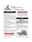
IDEALARC ™ AC-1500
IM914
October, 2010
Single Phase Variable Voltage Power Source For Automatic AC Welding
For use with machines having Code Numbers 11418
Safety Depends on You
Lincoln arc welding and cutting
equipment is designed and built
with safety in mind. However,
your overall safety can be
increased by proper installation
... and thoughtful operation on
your part. DO NOT INSTALL,
OPERATE OR REPAIR THIS
EQUIPMENT WITHOUT READING THIS MANUAL AND THE
SAFETY PRECAUTIONS CONTAINED THROUGHOUT. And,
most importantly, think before
you act and be careful.
OPERATOR’S MANUAL
Copyright © Lincoln Global Inc.
• World's Leader in Welding and Cutting Products •
• Sales and Service through Subsidiaries and Distributors Worldwide •
Cleveland, Ohio 44117-1199 U.S.A. TEL: 216.481.8100 FAX: 216.486.1751 WEB SITE: www.lincolnelectric.com
i
i
SAFETY
WARNING
CALIFORNIA PROPOSITION 65 WARNINGS
Diesel engine exhaust and some of its constituents
are known to the State of California to cause cancer, birth defects, and other reproductive harm.
The Above For Diesel Engines
The engine exhaust from this product contains
chemicals known to the State of California to cause
cancer, birth defects, or other reproductive harm.
The Above For Gasoline Engines
ARC WELDING CAN bE HAzARDOUS. PROTECT YOURSELF AND OTHERS FROM POSSIbLE SERIOUS INJURY OR DEATH.
KEEP CHILDREN AWAY. PACEMAKER WEARERS SHOULD CONSULT WITH THEIR DOCTOR bEFORE OPERATING.
Read and understand the following safety highlights. For additional safety information, it is strongly recommended that you
purchase a copy of “Safety in Welding & Cutting - ANSI Standard Z49.1” from the American Welding Society, P.O. Box
351040, Miami, Florida 33135 or CSA Standard W117.2-1974. A Free copy of “Arc Welding Safety” booklet E205 is available
from the Lincoln Electric Company, 22801 St. Clair Avenue, Cleveland, Ohio 44117-1199.
bE SURE THAT ALL INSTALLATION, OPERATION, MAINTENANCE AND REPAIR PROCEDURES ARE
PERFORMED ONLY bY QUALIFIED INDIVIDUALS.
FOR ENGINE
powered equipment.
1.h. To avoid scalding, do not remove the
radiator pressure cap when the engine is
hot.
1.a. Turn the engine off before troubleshooting and maintenance
work unless the maintenance work requires it to be running.
____________________________________________________
1.b. Operate engines in open, well-ventilated
areas or vent the engine exhaust fumes
outdoors.
____________________________________________________
1.c. Do not add the fuel near an open flame
welding arc or when the engine is running.
Stop the engine and allow it to cool before
refueling to prevent spilled fuel from vaporizing on contact with hot engine parts and
igniting. Do not spill fuel when filling tank. If
fuel is spilled, wipe it up and do not start
engine until fumes have been eliminated.
____________________________________________________
1.d. Keep all equipment safety guards, covers and devices in
position and in good repair.Keep hands, hair, clothing and
tools away from V-belts, gears, fans and all other moving
parts when starting, operating or repairing equipment.
____________________________________________________
1.e. In some cases it may be necessary to remove safety
guards to perform required maintenance. Remove
guards only when necessary and replace them when the
maintenance requiring their removal is complete.
Always use the greatest care when working near moving
parts.
___________________________________________________
1.f. Do not put your hands near the engine fan.
Do not attempt to override the governor or
idler by pushing on the throttle control rods
while the engine is running.
___________________________________________________
1.g. To prevent accidentally starting gasoline engines while
turning the engine or welding generator during maintenance
work, disconnect the spark plug wires, distributor cap or
magneto wire as appropriate.
ELECTRIC AND
MAGNETIC FIELDS
may be dangerous
2.a. Electric current flowing through any conductor causes
localized Electric and Magnetic Fields (EMF). Welding
current creates EMF fields around welding cables and
welding machines
2.b. EMF fields may interfere with some pacemakers, and
welders having a pacemaker should consult their physician
before welding.
2.c. Exposure to EMF fields in welding may have other health
effects which are now not known.
2.d. All welders should use the following procedures in order to
minimize exposure to EMF fields from the welding circuit:
2.d.1. Route the electrode and work cables together - Secure
them with tape when possible.
2.d.2. Never coil the electrode lead around your body.
2.d.3. Do not place your body between the electrode and
work cables. If the electrode cable is on your right
side, the work cable should also be on your right side.
2.d.4. Connect the work cable to the workpiece as close as
possible to the area being welded.
2.d.5. Do not work next to welding power source.
ii
ii
SAFETY
ELECTRIC SHOCK can
kill.
3.a. The electrode and work (or ground) circuits
are electrically “hot” when the welder is on.
Do not touch these “hot” parts with your bare
skin or wet clothing. Wear dry, hole-free
gloves to insulate hands.
3.b. Insulate yourself from work and ground using dry insulation.
Make certain the insulation is large enough to cover your full
area of physical contact with work and ground.
In addition to the normal safety precautions, if welding
must be performed under electrically hazardous
conditions (in damp locations or while wearing wet
clothing; on metal structures such as floors, gratings or
scaffolds; when in cramped positions such as sitting,
kneeling or lying, if there is a high risk of unavoidable or
accidental contact with the workpiece or ground) use
the following equipment:
• Semiautomatic DC Constant Voltage (Wire) Welder.
• DC Manual (Stick) Welder.
• AC Welder with Reduced Voltage Control.
3.c. In semiautomatic or automatic wire welding, the electrode,
electrode reel, welding head, nozzle or semiautomatic
welding gun are also electrically “hot”.
3.d. Always be sure the work cable makes a good electrical
connection with the metal being welded. The connection
should be as close as possible to the area being welded.
3.e. Ground the work or metal to be welded to a good electrical
(earth) ground.
3.f. Maintain the electrode holder, work clamp, welding cable and
welding machine in good, safe operating condition. Replace
damaged insulation.
3.g. Never dip the electrode in water for cooling.
3.h. Never simultaneously touch electrically “hot” parts of
electrode holders connected to two welders because voltage
between the two can be the total of the open circuit voltage
of both welders.
3.i. When working above floor level, use a safety belt to protect
yourself from a fall should you get a shock.
ARC RAYS can burn.
4.a. Use a shield with the proper filter and cover
plates to protect your eyes from sparks and
the rays of the arc when welding or observing
open arc welding. Headshield and filter lens
should conform to ANSI Z87. I standards.
4.b. Use suitable clothing made from durable flame-resistant
material to protect your skin and that of your helpers from
the arc rays.
4.c. Protect other nearby personnel with suitable, non-flammable
screening and/or warn them not to watch the arc nor expose
themselves to the arc rays or to hot spatter or metal.
FUMES AND GASES
can be dangerous.
5.a. Welding may produce fumes and gases
hazardous to health. Avoid breathing these
fumes and gases. When welding, keep
your head out of the fume. Use enough
ventilation and/or exhaust at the arc to keep
fumes and gases away from the breathing zone. When
welding with electrodes which require special
ventilation such as stainless or hard facing (see
instructions on container or MSDS) or on lead or
cadmium plated steel and other metals or coatings
which produce highly toxic fumes, keep exposure as
low as possible and within applicable OSHA PEL and
ACGIH TLV limits using local exhaust or mechanical
ventilation. In confined spaces or in some circumstances, outdoors, a respirator may be required.
Additional precautions are also required when welding
on galvanized steel.
5. b. The operation of welding fume control equipment is affected
by various factors including proper use and positioning of
the equipment, maintenance of the equipment and the specific welding procedure and application involved. Worker
exposure level should be checked upon installation and
periodically thereafter to be certain it is within applicable
OSHA PEL and ACGIH TLV limits.
5.c. Do not weld in locations near chlorinated hydrocarbon vapors
coming from degreasing, cleaning or spraying operations.
The heat and rays of the arc can react with solvent vapors to
form phosgene, a highly toxic gas, and other irritating products.
3.j. Also see Items 6.c. and 8.
5.d. Shielding gases used for arc welding can displace air and
cause injury or death. Always use enough ventilation,
especially in confined areas, to insure breathing air is safe.
5.e. Read and understand the manufacturer’s instructions for this
equipment and the consumables to be used, including the
material safety data sheet (MSDS) and follow your
employer’s safety practices. MSDS forms are available from
your welding distributor or from the manufacturer.
5.f. Also see item 1.b.
iii
iii
SAFETY
WELDING and CUTTING
SPARKS can
cause fire or explosion.
6.a. Remove fire hazards from the welding area.
If this is not possible, cover them to prevent
the welding sparks from starting a fire.
Remember that welding sparks and hot
materials from welding can easily go through small cracks
and openings to adjacent areas. Avoid welding near
hydraulic lines. Have a fire extinguisher readily available.
6.b. Where compressed gases are to be used at the job site,
special precautions should be used to prevent hazardous
situations. Refer to “Safety in Welding and Cutting” (ANSI
Standard Z49.1) and the operating information for the
equipment being used.
6.c. When not welding, make certain no part of the electrode
circuit is touching the work or ground. Accidental contact
can cause overheating and create a fire hazard.
6.d. Do not heat, cut or weld tanks, drums or containers until the
proper steps have been taken to insure that such procedures
will not cause flammable or toxic vapors from substances
inside. They can cause an explosion even though they have
been “cleaned”. For information, purchase “Recommended
Safe Practices for the Preparation for Welding and Cutting of
Containers and Piping That Have Held Hazardous
Substances”, AWS F4.1 from the American Welding Society
(see address above).
6.e. Vent hollow castings or containers before heating, cutting or
welding. They may explode.
6.f. Sparks and spatter are thrown from the welding arc. Wear oil
free protective garments such as leather gloves, heavy shirt,
cuffless trousers, high shoes and a cap over your hair. Wear
ear plugs when welding out of position or in confined places.
Always wear safety glasses with side shields when in a
welding area.
6.g. Connect the work cable to the work as close to the welding
area as practical. Work cables connected to the building
framework or other locations away from the welding area
increase the possibility of the welding current passing
through lifting chains, crane cables or other alternate circuits. This can create fire hazards or overheat lifting chains
or cables until they fail.
6.h. Also see item 1.c.
CYLINDER may explode
if damaged.
7.a. Use only compressed gas cylinders
containing the correct shielding gas for the
process used and properly operating
regulators designed for the gas and
pressure used. All hoses, fittings, etc. should be suitable for
the application and maintained in good condition.
7.b. Always keep cylinders in an upright position securely
chained to an undercarriage or fixed support.
7.c. Cylinders should be located:
• Away from areas where they may be struck or subjected to
physical damage.
• A safe distance from arc welding or cutting operations and
any other source of heat, sparks, or flame.
7.d. Never allow the electrode, electrode holder or any other
electrically “hot” parts to touch a cylinder.
7.e. Keep your head and face away from the cylinder valve outlet
when opening the cylinder valve.
7.f. Valve protection caps should always be in place and hand
tight except when the cylinder is in use or connected for
use.
7.g. Read and follow the instructions on compressed gas
cylinders, associated equipment, and CGA publication P-l,
“Precautions for Safe Handling of Compressed Gases in
Cylinders,” available from the Compressed Gas Association
1235 Jefferson Davis Highway, Arlington, VA 22202.
FOR ELECTRICALLY
powered equipment.
8.a. Turn off input power using the disconnect
switch at the fuse box before working on
the equipment.
8.b. Install equipment in accordance with the U.S. National
Electrical Code, all local codes and the manufacturer’s
recommendations.
8.c. Ground the equipment in accordance with the U.S. National
Electrical Code and the manufacturer’s recommendations.
6.I. Read and follow NFPA 51B “ Standard for Fire Prevention
During Welding, Cutting and Other Hot Work”, available
from NFPA, 1 Batterymarch Park, PO box 9101, Quincy, Ma
022690-9101.
6.j. Do not use a welding power source for pipe thawing.
Refer to http://www.lincolnelectric.com/safety for additional safety information.
iv
SAFETY
PRÉCAUTIONS DE SÛRETÉ
Pour votre propre protection lire et observer toutes les instructions
et les précautions de sûreté specifiques qui parraissent dans ce
manuel aussi bien que les précautions de sûreté générales suivantes:
Sûreté Pour Soudage A L’Arc
1. Protegez-vous contre la secousse électrique:
a. Les circuits à l’électrode et à la piéce sont sous tension
quand la machine à souder est en marche. Eviter toujours
tout contact entre les parties sous tension et la peau nue
ou les vétements mouillés. Porter des gants secs et sans
trous pour isoler les mains.
b. Faire trés attention de bien s’isoler de la masse quand on
soude dans des endroits humides, ou sur un plancher
metallique ou des grilles metalliques, principalement dans
les positions assis ou couché pour lesquelles une grande
partie du corps peut être en contact avec la masse.
c. Maintenir le porte-électrode, la pince de masse, le câble
de soudage et la machine à souder en bon et sûr état
defonctionnement.
d.Ne jamais plonger le porte-électrode dans l’eau pour le
refroidir.
e. Ne jamais toucher simultanément les parties sous tension
des porte-électrodes connectés à deux machines à souder
parce que la tension entre les deux pinces peut être le
total de la tension à vide des deux machines.
f. Si on utilise la machine à souder comme une source de
courant pour soudage semi-automatique, ces precautions
pour le porte-électrode s’applicuent aussi au pistolet de
soudage.
2. Dans le cas de travail au dessus du niveau du sol, se protéger
contre les chutes dans le cas ou on recoit un choc. Ne jamais
enrouler le câble-électrode autour de n’importe quelle partie
du corps.
3. Un coup d’arc peut être plus sévère qu’un coup de soliel,
donc:
a. Utiliser un bon masque avec un verre filtrant approprié
ainsi qu’un verre blanc afin de se protéger les yeux du rayonnement de l’arc et des projections quand on soude ou
quand on regarde l’arc.
b. Porter des vêtements convenables afin de protéger la
peau de soudeur et des aides contre le rayonnement de
l‘arc.
c. Protéger l’autre personnel travaillant à proximité au
soudage à l’aide d’écrans appropriés et non-inflammables.
4. Des gouttes de laitier en fusion sont émises de l’arc de
soudage. Se protéger avec des vêtements de protection libres
de l’huile, tels que les gants en cuir, chemise épaisse, pantalons sans revers, et chaussures montantes.
iv
5. Toujours porter des lunettes de sécurité dans la zone de
soudage. Utiliser des lunettes avec écrans lateraux dans les
zones où l’on pique le laitier.
6. Eloigner les matériaux inflammables ou les recouvrir afin de
prévenir tout risque d’incendie dû aux étincelles.
7. Quand on ne soude pas, poser la pince à une endroit isolé de
la masse. Un court-circuit accidental peut provoquer un
échauffement et un risque d’incendie.
8. S’assurer que la masse est connectée le plus prés possible
de la zone de travail qu’il est pratique de le faire. Si on place
la masse sur la charpente de la construction ou d’autres
endroits éloignés de la zone de travail, on augmente le risque
de voir passer le courant de soudage par les chaines de levage, câbles de grue, ou autres circuits. Cela peut provoquer
des risques d’incendie ou d’echauffement des chaines et des
câbles jusqu’à ce qu’ils se rompent.
9. Assurer une ventilation suffisante dans la zone de soudage.
Ceci est particuliérement important pour le soudage de tôles
galvanisées plombées, ou cadmiées ou tout autre métal qui
produit des fumeés toxiques.
10. Ne pas souder en présence de vapeurs de chlore provenant
d’opérations de dégraissage, nettoyage ou pistolage. La
chaleur ou les rayons de l’arc peuvent réagir avec les vapeurs
du solvant pour produire du phosgéne (gas fortement toxique)
ou autres produits irritants.
11. Pour obtenir de plus amples renseignements sur la sûreté,
voir le code “Code for safety in welding and cutting” CSA
Standard W 117.2-1974.
PRÉCAUTIONS DE SÛRETÉ POUR
LES MACHINES À SOUDER À
TRANSFORMATEUR ET À
REDRESSEUR
1. Relier à la terre le chassis du poste conformement au code de
l’électricité et aux recommendations du fabricant. Le dispositif
de montage ou la piece à souder doit être branché à une
bonne mise à la terre.
2. Autant que possible, I’installation et l’entretien du poste seront
effectués par un électricien qualifié.
3. Avant de faires des travaux à l’interieur de poste, la debrancher à l’interrupteur à la boite de fusibles.
4. Garder tous les couvercles et dispositifs de sûreté à leur
place.
v
v
Thank You
for selecting a QUALITY product by Lincoln Electric. We want you
to take pride in operating this Lincoln Electric Company product
••• as much pride as we have in bringing this product to you!
CUSTOMER ASSISTANCE POLICY
The business of The Lincoln Electric Company is manufacturing and selling high quality welding equipment, consumables, and cutting equipment. Our challenge is to meet the needs of our customers and to exceed their expectations. On occasion, purchasers may ask Lincoln
Electric for advice or information about their use of our products. We respond to our customers based on the best information in our possession at that time. Lincoln Electric is not in a position to warrant or guarantee such advice, and assumes no liability, with respect to such information or advice. We expressly disclaim any warranty of any kind, including any warranty of fitness for any customer’s particular purpose,
with respect to such information or advice. As a matter of practical consideration, we also cannot assume any responsibility for updating or
correcting any such information or advice once it has been given, nor does the provision of information or advice create, expand or alter any
warranty with respect to the sale of our products.
Lincoln Electric is a responsive manufacturer, but the selection and use of specific products sold by Lincoln Electric is solely within the control
of, and remains the sole responsibility of the customer. Many variables beyond the control of Lincoln Electric affect the results obtained in
applying these types of fabrication methods and service requirements.
Subject to Change – This information is accurate to the best of our knowledge at the time of printing. Please refer to www.lincolnelectric.com
for any updated information.
Please Examine Carton and Equipment For Damage Immediately
When this equipment is shipped, title passes to the purchaser upon receipt by the carrier. Consequently, Claims
for material damaged in shipment must be made by the purchaser against the transportation company at the
time the shipment is received.
Please record your equipment identification information below for future reference. This information can be
found on your machine nameplate.
Product _________________________________________________________________________________
Model Number ___________________________________________________________________________
Code Number or Date Code_________________________________________________________________
Serial Number____________________________________________________________________________
Date Purchased___________________________________________________________________________
Where Purchased_________________________________________________________________________
Whenever you request replacement parts or information on this equipment, always supply the information you
have recorded above. The code number is especially important when identifying the correct replacement parts.
On-Line Product Registration
- Register your machine with Lincoln Electric either via fax or over the Internet.
• For faxing: Complete the form on the back of the warranty statement included in the literature packet
accompanying this machine and fax the form per the instructions printed on it.
• For On-Line Registration: Go to our WEb SITE at www.lincolnelectric.com. Choose “Quick Links” and then
“Product Registration”. Please complete the form and submit your registration.
Read this Operators Manual completely before attempting to use this equipment. Save this manual and keep it
handy for quick reference. Pay particular attention to the safety instructions we have provided for your protection.
The level of seriousness to be applied to each is explained below:
WARNING
This statement appears where the information must be followed exactly to avoid serious personal injury or loss of life.
CAUTION
This statement appears where the information must be followed to avoid minor personal injury or damage to this equipment.
vi
vi
TAbLE OF CONTENTS
Page
Installation.......................................................................................................................Section A
Technical Specifications .......................................................................................................A-1
Location ...............................................................................................................................A-2
Input Wiring ..........................................................................................................................A-2
Output Connections..............................................................................................................A-2
Wire Feeder Connections .............................................................................................A-2
Connection of AC-1500 to NA-4 with Switch for ‘Current Control’ .......................................A-3
Connection of AC-1500 to NA-4 with rheostat for current control or LT-6............................A-3
Output Studs ................................................................................................................A-4
Auxiliary Power ............................................................................................................A-4
Duty Cycle ............................................................................................................................A-4
________________________________________________________________________________
Operation.........................................................................................................................Section b
Safety Precautions and Graphic Symbols..............................................................B-1
Product Design Application ..................................................................................................B-2
Setting the Machine or Remote Control ...............................................................................B-2
Setting the Output Current ...................................................................................................B-2
Weld with Manual Electrodes ...............................................................................................B-2
Product Description .......................................................................................................B-2,B-3
________________________________________________________________________________
Accessories .....................................................................................................Section C
Optional Kit ............................................................................................................C-1
Maintenance ....................................................................................................Section D
Safety Precautions ................................................................................................D-1
________________________________________________________________________
Troubleshooting ..............................................................................................Section E
Safety Precautions.................................................................................................E-1
How to Use Troubleshooting Guide.......................................................................E-1
Troubleshooting Guide....................................................................................E-2,E-3
________________________________________________________________________
Wiring Diagrams and Dimension Print ..........................................................Section F
________________________________________________________________________
Parts Pages.................................................................................P-556, P-28, P-84 Series
________________________________________________________________________
A-1
A-1
INSTALLATION
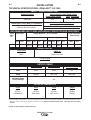
TECHNICAL SPECIFICATIONS - IDEALARC™ AC-1500
INPUT - SINGLE PHASE ONLY
Input Current at 100% Rated Output
Single Phase Output
Scott Connection
Standard Voltage
310
380/50/60
Rated Input Current With P.F. Capacitors
310 Amp Single Phase
358 Amp Scott-connection
358
Idle Current With P.F. Capacitors
70
Power Factor @ Rated load With P.F. Capacitors
71%
RECOMMENDED INPUT WIRE GROUNDING CONDUCTOR AND FUSE SIzES*
Input
Volts/
Hz.
380/50
Input Amps
Copper Wire Size – 75˚C in Conduit
Power Input Wires
1
Phase
310
Scott
Conn.
358
1
T&b
Phase
Term.
500MCM 31013
(250mm2)
Super Lag Fuses
Size in Amps
Grounding Conductor
Scott
T&b 1
T&b Scott
T&b
Conn.
Term. Phase Term. Conn.
Term.
600MCM 31015 #3
31007 #2
31007
(300mm2)
(25mm2)
(35mm2)
1
Phase
400
Scott
Conn.
500
RATED OUTPUT
Duty Cycle
AMPS AC
100%
1500 @ 44 Volts
Current Range
240/1500
OUTPUT (SMAW)
“MIN” Terminal
“MED” Terminal
“MAX” Terminal
Volts
30-44
38-44
44
Amps
240-600
460-1060
890-1500
Maximum Open
Circuit Voltage
86
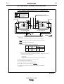
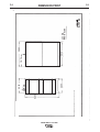
PHYSICAL DIMENSIONS
Height
Width
Depth
Weight
53.50 in.
( 1358.9mm.)
22.30 in.
(566.4mm.)
38.00in.
(965.2mm.)
1649lbs.
748(kg.)
* Thomas & Betts wire terminals (or equal) recommended above are required to comply with applicable U.L. standards for safety. A #30 hex
(Allen) key wrench is required for assembly of terminals to wire. Based on National Electrical Code - 100% Duty Cycle 40˚C (104˚F)
Ambient.
RATING: IP21 ENCLOSURE, INSULATION 155°(F)
IDEALARC™ AC-1500
A-2
INSTALLATION
LOCAtION
Install the welder in a dry location where there is free circulation of air in through the louvers in front and out through
the louvers in the back of the case. A location which minimizes the amount of smoke and dirt drawn into the
machine reduces the chance of dirt accumulation that can
block air passages and cause overheating.
INput WIRING
WARNING
ELECTRIC
SHOCK
can kill.
• Have an electrician install
and service this equipment.
• Turn the input power off at
the
fuse box before
working on
equipment.
• Do not touch electrically hot
parts.
Failure to fuse the input lines per the specifications
in this manual will constitute customer abuse and
void the warranty.
--------------------------------------------------------------Have a qualified electrician make the complete input connection in accordance with the National Electrical Code,
all local codes and the connection diagram located inside
the machine.
Be sure the voltage, phase and frequency of the input power
is as specified on the welder nameplate.
For most installations, connect the AC-1500 to single phase
power or to one phase of a three phase line. Unbalanced
line conditions can be easily avoided by properly balancing
the AC-1500 with other machinery on the lines.
When installing two or four Scott connected AC-1500
machines for AC-AC tandem arc welding, three phase input
power must be used. The terminals for connections to provide an output phase angle less than or greater than the
usual 90º phase angle are included on the input panel.
A-2
The AC-1500 does not have an input contactor. Therefore,
include an external starter or disconnect switch when planning the input circuit.
Remove the right side panel of the AC-1500 and bring the
input power lines through the hole in the back of the case.
See the table below for reccomended sizing of input leads
and overcurrent protection.
The frame of the welder must be grounded, A stud marked
with the symbol
located on the welder base below
the panel is provided for this purpose. See the National
Electrical Code for details on proper grounding methods.
Output CONNECtIONs
WIRE FEEDER CONNECtION
Turn the input power to the welder off. Remove the
screw and lift the hinged door on the front of the control
panel to expose the terminal strips. Connect the leads
of the wire feeder input control cable to the terminal
strips exactly as specified in the appropriate connection
diagram. The AC-1500 to NA-4 connection diagrams
are included in the NA-4 Operating Manual IM-278.
Attach the control cables to the panel at the right of the
terminal strip using the clamps provided.
If connecting the AC-1500 to an older NA-4 with the
toggle switch type ‘Current Control’ (below code 7532),
a K-775 ‘Remote Control’ must be purchased and installed in accordance with the connection diagram S-15667
on page 5. The ‘Remote Control’ cord can be lengthened
to any length by properly splicing a four conductor cord
to the standard 25’ cord before connecting to the AC1500 terminal strip.
To connect the AC-1500 to any other wire feeder, write
to the factory for instructions giving complete nameplate
information for the specific equipment.
When connection to the terminal strips are completed,
close the door and replace the screw.
IDEALARC™ AC-1500
A-3
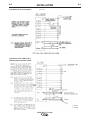
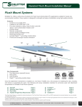
Connection of AC-1500 to NA-4
with switch for ‘Current Control’
INSTALLATION
A-3
S-15667
6-18-76A
Connection of AC-1500 to NA-4
with rheostat for current control.
S-15602
6-22-84H
IDEALARC™ AC-1500
A-4
INSTALLATION
Output stuDs
Connect the work cables to the ‘To Work’ stud on the
front of the AC-1500. Connect the electrode cables to
the ‘Min,’ ‘Med’ or ‘Max’ studs for the output desired.
Actual current ranges for each stud are indicated on the
nameplate above each stud. Recommended cable sizes
are listed below. Both the ‘To Work’ and ‘Max’ studs
have two terminals to simplify connection of recommended cables in parallel. Tighten the nuts with a wrench.
Select cables required for combined work and electrode
cable lengths up to 150’ from the following table:
Maximum Allowable Current for Copper Welding Cable
Duty
Cycle
100%
One 4/0
650
two 4/0
1000
Four 4/0
1200
Five 4/0
1500
Cables in accessory kit recommended below have terminals as required to comply with applicable U.L. standards for safety.
150’ combined length electrode and work cables.
AuxILIARy pOWER
1000 volt-amperes of 115 volt AC power are available
from #31 and #32 on the AC-1500 terminal strip.
Duty CyCle
The AC-1500 is rated for 100% duty cycle at 1500 amps
and 44 volts.
IDEALARC™ AC-1500
A-4
b-1
b-1
OPERATION
SAFETY PRECAUTIONS
Read and understand this entire section before operating the machine.
GRAPHIC SYMbOLS THAT APPEAR
ON THIS MACHINE OR IN THIS
MANUAL
Output Control
1
Single Phase
Remote Control Setting
3
Three Phase
Local Control Settin
Uo Rated No-Load Voltage
Input Power Type
U1 Rated Input Voltage
Submerged Arc Welding
U2 Rated Welding Voltage
WARNING
ELECTRIC SHOCK
can kill.
• Do not touch electrically live parts
or electrode with skin or wet
clothing.
• Insulate yourself from work and
ground.
• Always wear dry insulating
gloves.
Transformer Type
FUMES AND GASES
can be dangerous.
Fuse
• Keep your head out of fumes.
• Use ventilation or exhaust to
remove fumes from breathing
zone.
High Voltage Indicator
High Temperature Indicator
WELDING SPARKS
can cause fire or
explosion
Rated Frequency
• Keep flammable material away.
• Do not weld on containers that
have held combustibles.
ARC RAYS
can burn.
• Wear eye, ear and body
protection.
Observe additional Safety Guidelines detailed
throughout this manual.
IDEALARC™ AC-1500
X
Rated Duty Cycle
I1
Rated Input Current
I2
Rated Welding Current
b-2
OPERATION
b-2
PRODUCT DESIGN APPLICATION
PRODUCT DESCRIPTION
The IDEALARC™ AC-1500 is an upgraded design
with the following additional features:
Specifications are 50 Hz, 380 volt unit with a Power
factor correction as a standard feature.
• Higher output current and duty cycle capabilities.
It is a single phase transformer-saturable reactor type
power supply intended for use primarily in automatic
or semiautomatic variable voltage AC welding applications. It can be used to supply one automatic welder
head or two units may be used in Scott connection to
provide two phase power to two welder heads in tandem. The welder can be used as is with NA-4 heads
or modified with available options to supply the earlier
NA-4 or LAF-4, and LT-34 welding heads.
WARNING
Pipe Thawing with an arc welder can cause fire,
explosion, damage to electric wiring or to the arc
welder if done improperly. The use of an arc
welder for pipe thawing is not approved by the
CSA, nor is it recommended or supported by
Lincoln Electric.
------------------------------------------------------------------------
SETTING THE MACHINE OUTPUT OR
REMOTE CONTROL
The output can be controlled either from the AC-1500,
the wire feeder or other remote locations.
To adjust the current from the wire feeder or other
remote locations, set the toggle switch on the front of
the AC-1500 to ‘Output Control Remote’. To adjust the
output current from the AC-1500, set this switch to
‘Output Control at AC-1500’.
SETTING THE OUTPUT CURRENT
Start the AC-1500 using the line disconnect switch or
breaker installed with the input wiring. The red pilot
light on the front panel indicates when the welder is
on.
Adjust the output current from minimum to maximum
within the range set by the output stud connections
using either the ‘Output Control’ rheostat on the AC1500 (toggle switch set to ‘Local Control’) or the wire
feeder or other remote rheostat (toggle switch set to
‘Remote Control’).
Output terminals, control power terminal strip, and
controls are recessed or hinged covered to affect a
"dead front". Due to the excessive amount of stray
magnetic flux developed by the saturable reactor, the
center sections of the welder side panels are made of
a high impact, self-extinguishing, chemical resistant
plastic material. USE OF METALLIC PANELS IN
THEIR PLACE WILL RESULT IN EXCESSIVE HEATING OF THE PANELS AS WELL AS THE SHEET
METAL SCREWS USED IN THE ASSEMBLY OF
OTHER CASE PARTS.
Output welding current is available in three overlapping ranges by means of externally connecting the
electrode cables to the Min., Med., or Max. tap electrode studs(See Technical Specifications in the
Installation Section).
Input Line Voltage Compensation maintains a reasonably constant output within a range of ±10%
change in supply line voltage.
Cooling of the welder is accomplished by drawing air
in through the louvered case front panel, through the
reactor and transformer assemblies, and out the louvered case rear panel. The two totally enclosed fan
motors used have sealed ball bearings and require no
lubrication maintenance.
Handling of the welder and any attached devices
should be done with a fork-lift or pallet-jack capable of
loads exceeding the combined weight of the system.
Overload/Thermal Protection is provided in three
areas: the 115 volt AC auxiliary power is fused for 8
amps; the saturable reactor control power circuit is
protected by a 40 amp fuse; the welder output power
circuit is protected by the familiar current transformerKlixon thermostat breaker. In the event of a control circuit or welder overload, the output contactors will
open and the fan motors will continue to operate. If
the overload is detected by the thermostatic breaker,
the temperature light located on the front panel will
illuminate until a safe operating temperature is
reached.
Output Contactor control is provided by two S78
contactors connected in parallel. Input line contactors
are not provided. The customer is expected to provide
line starting and circuit breaking equipment.
IDEALARC™ AC-1500
b-3
OPERATION
b-3
Pilot light indicates when the supply lines to the
welder are electrically "hot". This means that the
welder input power and control transformers are energized when the pilot light is on.
Hand Welding with stick electrode or semiautomatic
arc welding is not recommended since OCV exceeds
the 80 volts RMS limit allowed by standards for such
use. (Unit is within 100 volt allowable limit for automatic or mechanically guided welding.)
Input Circuit Plan: The AC-1500 is not intended for
the connection of flexible supply cables. Instead, the
following table may be used for planning of supply
cables routed in conduit (See Technical Specifications
in the Installation Section).
Scott Connection information for tandem arc application and paralleling of Scott connected units for tandem arc application is available. (See list of wiring
diagrams.)
Starting Device: The pushbuttons located on the
front panel are not connected to any kind of starting or
stopping device. They are not necessary to operating
the welder. If pushbutton operation is desired, an input
contactor must be professionally installed and wired to
the pushbutton assembly. The AC-1500 does not
have an input contactor. Therefore, include an external starter or disconnect switch when planning the
input circuit. Once the input circuit is energized, the
pilot light on the front panel should glow. High voltage
is present inside the machine. Do not open the
machine enclosure.
Isolated Auxiliary Power of 1000 volt.-amp., 115
volts AC is available at terminals #31 and #32 on the
terminal strip under the hinged cover on the case front
panel of the welder. The circuit is fused with an 8
amp slow blow fuse located in the nameplated section
of the welder front panel.
Input Panel is made accessible by removal of the
right side panel assembly (as viewed from front).
Supply lines and grounding lead should be brought
into the welder through the hole provided in the case
rear panel. Connections to the input panel should be
made as instructed on the wiring diagram attached to
the welder. The grounding lead connection is to be
made to the grounding stud provided on the welder
base directly below the input panel.
Location of installation should be such that the
welder cooling air exhaust area (the case rear panel)
is free of any obstructions that could impede air flow.
A dry location should be chosen. The welder should
not be placed on a surface that is inclined enough that
it creates a risk of the machine falling over
Control Circuit connections for wire feeder equipment are to be made per instructions on the wire feeder diagram to the terminal strip provided under the
hinged cover on the case front panel of the welding
power supply. A strain relief strap to the right of the
terminal strip is provided for attaching either the feeder control and remote current control cables or both
simultaneously. A grounding screw located just to the
right of the terminal strip is provided for connecting the
wire feeder grounding lead. All connections must be
made with the welding power supply turned off.
IDEALARC™ AC-1500
C-1
ACCESSORIES
OPTIONAL KIT: Remote control K775.
IDEALARC™ AC-1500
C-1
D-1
MAINTENANCE
SAFETY PRECAUTIONS
WARNING
ELECTRIC SHOCK can kill.
• Have qualified personnel do the
maintenance and troubleshooting
work.
• Turn the input power OFF at the disconnect
switch or fuse box before working on this
equipment.
• Do not touch electrically live parts or electrode
with skin or wet clothing.
• Insulate yourself from work and ground.
• Always wear dry insulating gloves.
------------------------------------------------------------------------
See additional warning information
throughout this operator’s manual.
-----------------------------------------------------------Periodic blowing out of dust and dirt accumulated
within the welder using an air stream is recommended. This may be particularly desirable in atmospheres
containing chemical or metallic particles which could
accumulate within the welder and cause some difficulty.
The totally enclosed fan motors have sealed ball bearings which require no lubrication maintenance.
IDEALARC™ AC-1500
D-1
E-1
TROUbLESHOOTING
E-1
HOW TO USE TROUbLESHOOTING GUIDE
WARNING
Service and Repair should only be performed by Lincoln Electric Factory Trained Personnel.
Unauthorized repairs performed on this equipment may result in danger to the technician and
machine operator and will invalidate your factory warranty. For your safety and to avoid Electrical
Shock, please observe all safety notes and precautions detailed throughout this manual.
__________________________________________________________________________
This Troubleshooting Guide is provided to help you
locate and repair possible machine malfunctions.
Simply follow the three-step procedure listed below.
Step 1. LOCATE PROBLEM (SYMPTOM).
Look under the column labeled “PROBLEM (SYMPTOMS)”. This column describes possible symptoms
that the machine may exhibit. Find the listing that
best describes the symptom that the machine is
exhibiting.
Step 3. RECOMMENDED COURSE OF ACTION
This column provides a course of action for the
Possible Cause, generally it states to contact your
local Lincoln Authorized Field Service Facility.
If you do not understand or are unable to perform the
Recommended Course of Action safely, contact your
local Lincoln Authorized Field Service Facility.
Step 2. POSSIBLE CAUSE.
The second column labeled “POSSIBLE CAUSE” lists
the obvious external possibilities that may contribute
to the machine symptom.
CAUTION
If for any reason you do not understand the test procedures or are unable to perform the tests/repairs safely, contact your
Local Lincoln Authorized Field Service Facility for technical troubleshooting assistance before you proceed.
IDEALARC™ AC-1500
E-2
E-2
TROUbLESHOOTING
Observe all Safety Guidelines detailed throughout this manual
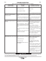
PRObLEMS
(SYMPTOMS)
Welder will not start.
POSSIbLE
CAUSE
RECOMMENDED
COURSE OF ACTION
Supply line fuse blown.
Look for possible cause and repair.
Open supply line lead.
Replace fuse.
Wrong supply line voltage.
Repair.
Provide nameplate specified voltage.
Welder will not weld (Contactors
operating properly)
Electrode or ground cable loose or Tighten connection or repair broken
broken.
cable.
Welder control circuit dead: No volt- Check Control Transformer primary
age across Control Transformer X1- voltage and if OK, replace transX2.
former.
Welder will not weld (Contactors not Thermostat on coil tripped. Welder Check operation of fans and make
operating).
overheated (Fan motors operating). sure there is no obstruction to air
flow. Do not operate in excess of
Fuse (or thermostat – below code welder rating.
7600) on control panel open; Control
circuit overloaded. (Fan motors oper- SCR’s or diodes on heat sink
ating)
assembly or P.C. board failed –see
Trouble “Welder welds at max. or
Circuit across #2 and #4 not working min. only – no control”. Make repairs
properly.
and replace fuse.
Wire feeder control power; No volt- Check connections at terminal strip
age across #31 and #32.
and wire feeder. Relay contacts not
closing. Repair as required.
Check fuse and replace if no good.
Welder welds at min. only no control. Remote control switch in wrong posi- Switch to ‘Panel Control’ for welder
rheostat. Control and “Remote
tion.
Control” for other control.
Control rheostat open.
Replace rheostat.
Control circuit open.
1.No voltage across #41 and #44 –
Repair broken leads or reconnect
loose leads.
Open saturable reactor control coil
or connection.
2. Diodes or SCR’s on heat sinks open
or disconnected. Repair or replace.
3. P.C. board plug disconnected – Check
plug connection and plug in properly.
4. P.C. board failed. Determine cause
and replace board.
5. Open circuit ar R1 – Repair or replace.
Repair connection or replace coil.
CAUTION
If for any reason you do not understand the test procedures or are unable to perform the tests/repairs safely, contact your
Local Lincoln Authorized Field Service Facility for technical troubleshooting assistance before you proceed.
IDEALARC™ AC-1500
E-3
E-3
TROUbLESHOOTING
PRObLEMS
(SYMPTOMS)
Welder welds at max. only no control.
POSSIbLE
CAUSE
RECOMMENDED
COURSE OF ACTION
Diodes or SCR’s on heat sink Determine cause if possible and
replace shorted device.
assemblies shorted.
Shorted or grounded current controll Replace rheostat.
rheostat.
Output By-Pass Capacitors open or Replace or reconnect.
disconnected.
Free wheeling diode open or discon- Replace or reconnect.
nected.
Contacts chatter.
P.C. board components failed.
Determine cause if possible and
replace P.C. board.
Low supply line voltage.
Check with Power Company.
Faulty contactor.
Repair or replace.
CAUTION
If for any reason you do not understand the test procedures or are unable to perform the tests/repairs safely, contact your
Local Lincoln Authorized Field Service Facility for technical troubleshooting assistance before you proceed.
IDEALARC™ AC-1500
BASE
IDEALARC™ AC-1500
T2 AUX.
TRANSFORMER
H7
B
T3
CONTROL
BOARD
TRANSFORMER
R
X1
58
48V
115V
H5
H4
H10
H9
H8
R
B
1
FS
2
FS
3
FS
N.C.
1 1
REMOTE
CURRENT
CONTROL
58
FILTER
CHOKE
59
75
76
77
31
32
21
4
2
FUSE
R
4
FS
5
FS
REMOTE
CONTROL
SWITCH
57
58
OUTPUT
CONTACTORS
CONTROL
CIRCUIT
THERMOSTAT
FUSE
TRANSFORMER
44
S
1
N.B.
FS
53
2
77
52
76
46
FS
2
4
21
FS
MTR
5
REMOTE
F
B
B
53
Y
75
49
DIODE ASSEMBLY
R1
43
45
41
46
44
48
49
CURRENT CONTROL
POTENTIOMETER
42
X2
X1
52
1 2 3 4 5 6 7 8 9 10 1112
CONTROL
P.C. BOARD
55
SUPPRESSION ASSEMBLY
SCR ASSEMBLY
THERMAL
TRIP
LIGHT
41
44
REAR VIEW RIGHT
SIDE TERMINAL
CONTACTOR
RESISTORS
OUTPUT
BY-PASS
CAPACITORS
WORK
MAX.
MED.
MIN.
TOP TERMINALS
PANEL
57
3
THERMOSTAT
1
3
54
MTR
FS
55
CONTROL
COILS
(RIGHT)
56
44
43
42
41
X1
X2
1
48
U
FUSE
B
M18868-1
U
U U
45
84
44
34
24
14
1X
2X
1
65
YLBMESSA EDOID
14
44
LORTNOC TNERRUC
RETEMOITNETOP
94
57
THGIR WEIV RAER
LANIMRET EDIS
B
Y
KRO W
.XAM
.DEM
.NIM
F
5
LORTNOC
SLIOC
)THGIR(
55
35
SF
2
4
RT M
SF
75
3
1
ETOMER
SF
67
64
77
25
RT M
45
3
TATSOMREHT
SLANIMRET POT
LENAP
ROTCATNOC
SROTSISER
TUPTUO
SSAP-YB
SROTICAPAC 12
B
35
2
. B. N
SF
1
5
SF
75
ETOMER
LORTNOC
HCTI WS
85
4
SF
3
SF
2
12
4
2
57
67
77
13
23
S
44
65
1
85
R E T LI F
EKOHC
ETOMER
TNERRUC
LORTNOC
.C.N
1 1
95
LORTNOC
TIUCRIC
ESUF
SF
LORTNOC
SLIOC
)TFEL(
ESUF
R
TATSOMREHT
REMROFSNART
TUPTUO
SROTCATNOC
SF
MARGAID GNIRI W 0051-CA CRALAEDI
25 2X 84 64
54 34
1X 94 44
14 24
LAMREHT
PIRT
THGIL
21 11 01 9 8 7 6 5 4 3 2 1
LORTNOC
DRAOB .C.P
YLBMESSA RCS
55
YLBMESSA NOISSERPPUS
1R
8H
9H
4H
01H
5H
V84
V511
85
B
R
7H
R
B
:SETON
.ESUF WOLB WOLS PMA 01 .B.N
.YLBMESSA ROTSISER MHO K11 .C.N
NAF
ELFFAB
1 8 4
01 9 7
.XUA 2T
REMROFSNART
3T
LORTNOC
DRAOB
REMROFSNART
ESAC
TNORF
EDOC ROLOC DAEL
KCALB - B
E ULB - U
DER - R
ROTCAF RE WOP
SROTICAPAC
TUPNI
RE WOP
SENIL
SLOBMYS LACIRTCELE
7351E REP
{
DNUORG OT TCENNOC
LANOITAN REP
EDOC LACIRTCELE
ESAB
TIUCRIC GNIDNOB EVITCETORP
ROTCAER .TAS
1T
1H
1X
2X
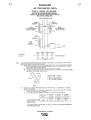
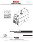
DIAGRAMS
NOTE: This diagram is for reference only. It may not be accurate for all machines covered by this manual. The specific diagram for a particular code is pasted inside the
machine on one of the enclosure panels. If the diagram is illegible, write to the Service Department for a replacement. Give the equipment code number.
ELECTRICAL SYMBOLS
PER E1537
LEAD COLOR CODE
B - BLACK
U - BLUE
R - RED
{
4 8 1
7 9 10
SAT. REACTOR
T1
X2
H1
FAN
BAFFLE
56
CONTROL
COILS
(LEFT)
54
U
U U
U
F-1
POWER FACTOR
CAPACITORS
INPUT
POWER
LINES
CONNECT TO GROUND
PER NATIONAL
ELECTRICAL CODE
CASE
FRONT
PROTECTIVE BONDING CIRCUIT
N.B. 10 AMP SLOW BLOW FUSE.
N.C. 11K OHM RESISTOR ASSEMBLY.
NOTES:
IDEALARC AC-1500 WIRING DIAGRAM
B
1-86881M
2T1X
H2T2
2T2X
X2T2
FUSE
H1T2
2 T1 H
X1T2
2 T2 H
F-1
F-2
F-2
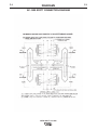
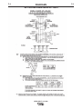
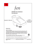
DIAGRAMS
AC-1500 sCOtt CONNECtION DIAGRAM
M13026
B
future applications.
N.E. The weld cables for each arc, and work must be of proper capacity for the current and duty cycle of the immediate and
N.D. Electrode cables of paralleled machines should be connected to the same range tap.
N.C. Frames of all welding power sources must be grounded per National Electric Code.
N.B. Interconnect machines as shown for the desired phase angle.
N.A. To obtain proper phase sequence at the welding arcs, the input line sequence must be A-C-B.
3. Temporarily reconnect the machine to either the 100 o tap or the 80 o tap and check the voltage per note 2.
2. Use an oscilloscope.
1. Use a phase meter.
the phase sequence use one of the following methods.
If using the 90 phase angle connection, the phase sequence cannot be determined by voltage measurement. To determine
o
80 o
90 o
100 o
ANGLE
PHASE
90 VAC
90 VAC
90 VAC
90 VAC
90 VAC
90 VAC
V
TO WORK
LEAD ARC
116 VAC
127 VAC
138 VAC
V
TO WORK
TRAIL ARC
1.29 x V
1.41 x V
1.53 x V
*
Value
Relationship
TRAIL ARC
LEAD ARC TO
CAUTION - Voltage will be high between the two electrode nozzles.
buttons.
1. Do not weld during the voltage measurements. Back the electrode out of each wire drive, then press the NA-4 start
A way to verify the proper phase angle and phase sequence is to measure the A.C. voltage at the welding nozzles.
TRAVEL
WORK
ARC
TRAIL
.CES
YRAMIRP
LEAD ARC
AC-1200 OR AC1500
MAIN TRANSFORMER (LEAD ARC)
80
90
N.B.
N.C.
4
10
9
8
7
1
WORK
.CES
4
10
9
8
7
1
YRAMIRP
WORK
ELEC.
ELEC.
N.C.
N.D.,N.E.
CAN KILL
ELECTRIC SHOCK
C
or service this equipment.
Only qualified persons should install, use
Do not touch electrically live parts.
Do not operate with covers removed.
Disconnect input power before servicing.
B
A100
PHASE SEQUENCE A-C-B (N.A.)
3 PHASE SUPPLY LINES
WARNING
TWO SINGLE MACHINES SCOTT CONNECTED
TWO SINGLE MACHINES SCOTT CONNECTED
WARNING
ELECTRIC SHOCK
CAN KILL
Disconnect input power before servicing.
Do not operate with covers removed.
Do not touch electrically live parts.
Only qualified persons should install, use
or service this equipment.
3 PHASE SUPPLY LINES
PHASE SEQUENCE A-C-B (N.A.)
C
B
A
N.D.,N.E.
N.D.,N.E.
N.C.
SEC.
100
90
80
N.B.
TEASER TRANSFORMER (TRAIL ARC)
AC-1200 OR AC1500
WORK
ELEC.
1
7
8
9
10
4
SEC.
WORK
1
7
8
9
10
4
N.C.
PRIMARY
ELEC.
PRIMARY
*
If voltages do not agree, recheck all wiring and the proper sequence of the input supply lines.
2. Voltage readings between nozzles to work, and nozzle to nozzle should be per table:
welding will result.
NOTE: The two arcs must be properly phased relative to each other, if the electrical connections are not as shown above, poor
AC-1200 OR AC1500
TEASER TRANSFORMER (TRAIL ARC)
N.D.,N.E.
WORK
MAIN TRANSFORMER (LEAD ARC)
AC-1200 OR AC1500
TRAIL
ARC
LEAD ARC
TRAVEL
NOTE: The two arcs must be properly phased relative to each other, if the electrical connections are not as shown above, poor
welding will result.
A way to verify the proper phase angle and phase sequence is to measure the A.C. voltage at the welding nozzles.
1. Do not weld during the voltage measurements. Back the electrode out of each wire drive, then press the NA-4 start
buttons.
CAUTION - Voltage will be high between the two electrode nozzles.
2. Voltage readings between nozzles to work, and nozzle to nozzle should be per table:
PHASE
ANGLE
100 o
90 o
80 o
LEAD ARC
TO WORK
V
TRAIL ARC
TO WORK
V
90 VAC
90 VAC
90 VAC
90 VAC
90 VAC
90 VAC
LEAD ARC TO
TRAIL ARC
Value
Relationship
138 VAC
127 VAC
116 VAC
1.53 x V
1.41 x V
1.29 x V
*
If voltages do not agree, recheck all wiring and the proper sequence of the input supply lines.
*
o
If using the 90 phase angle connection, the phase sequence cannot be determined by voltage measurement. To determine
the phase sequence use one of the following methods.
1. Use a phase meter.
2. Use an oscilloscope.
3. Temporarily reconnect the machine to either the 100 o tap or the 80 o tap and check the voltage per note 2.
N.A. To obtain proper phase sequence at the welding arcs, the input line sequence must be A-C-B.
N.B. Interconnect machines as shown for the desired phase angle.
N.C. Frames of all welding power sources must be grounded per National Electric Code.
N.D. Electrode cables of paralleled machines should be connected to the same range tap.
N.E. The weld cables for each arc, and work must be of proper capacity for the current and duty cycle of the immediate and
future applications.
B
M13026
IDEALARC™ AC-1500
F-3
DIAGRAMS
AC-1500 sCOtt CONNECtION DIAGRAM
IDEALARC™ AC-1500
F-3
F-4
DIAGRAMS
AC-1500 AND pARALLELED DC-1000’s
M14364
4-8-83E
IDEALARC™ AC-1500
F-4
F-5
DIAGRAMS
AC-1500 AND DC-1500’s
IDEALARC™ AC-1500
F-5
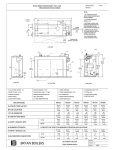
53.50
20.00
3.69
22.30
18.74
36.12
38.00
.406 DIA.
MTG. HOLES
IDEALARC™ AC-1500
4-18-75B
S-15709
B 5 7- 8 1- 4
90751-S
.AID 604.
SELOH .GTM
21.63
00.83
47.81
96.3
03.22
00.02
05.35
F-6
DIMENSION PRINT
F-6
NOTES
IDEALARC™ AC-1500
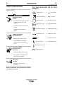
• Do not touch electrically live parts or
WARNING
Spanish
AVISO DE
PRECAUCION
French
ATTENTION
German
WARNUNG
Portuguese
ATENÇÃO
• Keep flammable materials away.
• Wear eye, ear and body protection.
• Mantenga el material combustible
• Protéjase los ojos, los oídos y el
electrode with skin or wet clothing.
• Insulate yourself from work and
ground.
• No toque las partes o los electrodos
bajo carga con la piel o ropa mojada.
• Aislese del trabajo y de la tierra.
• Ne laissez ni la peau ni des vête-
ments mouillés entrer en contact
avec des pièces sous tension.
• Isolez-vous du travail et de la terre.
• Berühren Sie keine stromführenden
fuera del área de trabajo.
• Gardez à l’écart de tout matériel
inflammable.
• Entfernen Sie brennbarres Material!
Teile oder Elektroden mit Ihrem
Körper oder feuchter Kleidung!
• Isolieren Sie sich von den
Elektroden und dem Erdboden!
• Não toque partes elétricas e electro-
dos com a pele ou roupa molhada.
• Isole-se da peça e terra.
cuerpo.
• Protégez vos yeux, vos oreilles et
votre corps.
• Tragen Sie Augen-, Ohren- und Kör-
perschutz!
• Mantenha inflamáveis bem guarda-
dos.
• Use proteção para a vista, ouvido e
corpo.
Japanese
Chinese
Korean
Arabic
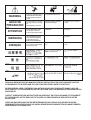
READ AND UNDERSTAND THE MANUFACTURER’S INSTRUCTION FOR THIS EQUIPMENT AND THE
CONSUMABLES TO BE USED AND FOLLOW YOUR EMPLOYER’S SAFETY PRACTICES.
SE RECOMIENDA LEER Y ENTENDER LAS INSTRUCCIONES DEL FABRICANTE PARA EL USO DE
ESTE EQUIPO Y LOS CONSUMIBLES QUE VA A UTILIZAR, SIGA LAS MEDIDAS DE SEGURIDAD DE SU
SUPERVISOR.
LISEZ ET COMPRENEZ LES INSTRUCTIONS DU FABRICANT EN CE QUI REGARDE CET EQUIPMENT
ET LES PRODUITS A ETRE EMPLOYES ET SUIVEZ LES PROCEDURES DE SECURITE DE VOTRE
EMPLOYEUR.
LESEN SIE UND BEFOLGEN SIE DIE BETRIEBSANLEITUNG DER ANLAGE UND DEN ELEKTRODENEINSATZ DES HERSTELLERS. DIE UNFALLVERHÜTUNGSVORSCHRIFTEN DES ARBEITGEBERS
SIND EBENFALLS ZU BEACHTEN.
• Keep your head out of fumes.
• Use ventilation or exhaust to
• Turn power off before servicing.
• Do not operate with panel open or
guards off.
remove fumes from breathing zone.
• Los humos fuera de la zona de res-
piración.
• Mantenga la cabeza fuera de los
humos. Utilice ventilación o
aspiración para gases.
• Gardez la tête à l’écart des fumées.
• Utilisez un ventilateur ou un aspira-
• Desconectar el cable de ali-
mentación de poder de la máquina
antes de iniciar cualquier servicio.
• Débranchez le courant avant l’entre-
tien.
teur pour ôter les fumées des zones
de travail.
• Vermeiden Sie das Einatmen von
Schweibrauch!
• Sorgen Sie für gute Be- und
Entlüftung des Arbeitsplatzes!
• Mantenha seu rosto da fumaça.
• Use ventilação e exhaustão para
remover fumo da zona respiratória.
• Strom vor Wartungsarbeiten
abschalten! (Netzstrom völlig öffnen;
Maschine anhalten!)
• Não opere com as tampas removidas.
• Desligue a corrente antes de fazer
serviço.
• Não toque as partes elétricas nuas.
• No operar con panel abierto o
guardas quitadas.
• N’opérez pas avec les panneaux
ouverts ou avec les dispositifs de
protection enlevés.
• Anlage nie ohne Schutzgehäuse
oder Innenschutzverkleidung in
Betrieb setzen!
• Mantenha-se afastado das partes
moventes.
• Não opere com os paineis abertos
ou guardas removidas.
WARNING
Spanish
AVISO DE
PRECAUCION
French
ATTENTION
German
WARNUNG
Portuguese
ATENÇÃO
Japanese
Chinese
Korean
Arabic
LEIA E COMPREENDA AS INSTRUÇÕES DO FABRICANTE PARA ESTE EQUIPAMENTO E AS PARTES
DE USO, E SIGA AS PRÁTICAS DE SEGURANÇA DO EMPREGADOR.
• World's Leader in Welding and Cutting Products •
• Sales and Service through Subsidiaries and Distributors Worldwide •
Cleveland, Ohio 44117-1199 U.S.A. TEL: 216.481.8100 FAX: 216.486.1751 WEB SITE: www.lincolnelectric.com