Transcript
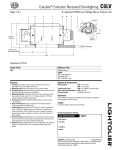
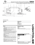
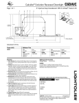
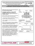
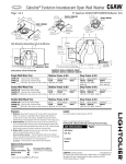
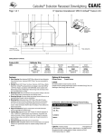
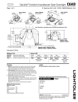
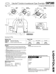
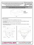
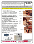
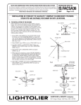
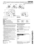
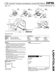
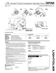
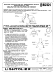
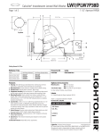
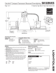
1
READ
AND UNDERSTAND THESE INSTRUCTIONS BEFORE INSTALLING ACCESSORY
INSTRUCTION SHEET NO.
This accessory is intended for installation in accordance with the National Electrical Code and local regulations.
To assure full compliance with local codes and regulations, check with your local electrical inspector before
installation. To prevent electric shock, turn off electricity at fuse box before proceeding.
IS:C6TCAA
Retain these instructions for maintenance reference.
Page 1 of 1
A0502
INSTALLATION PROCEDURE FOR C6TCAA CALCULITE EVOLUTION
6 INCH APERTURE THICK CEILING ADAPTER SPRINGS
CAUTION-TO AVOID OVERHEATING: DO NOT USE THIS PRODUCT WITH C6AIC, C6AICLV, or C6DAIC
FRAMES AND/OR C6P36A SERIES TRIMS WITH DATE CODE OF 2402 OR EARLIER. (2402 = WEEK 24, 2002)
CAT.
LISTED
R
xxxxxxxxxxxxxxxxxxxxxxxxxxx
xxxxxxxxxxxxxxxxxxxxxxxxxxx
xxxxxxxxxxxxxxxxxxxxxxxxxxx
xxxxxxxxxxxxxxxxxxxxxxxxxxx
C6TCAA
6” Aperture
Thick Ceiling Adapter
(3 pieces required, kit
contains one extra piece)
FIG. 1
C6AIC
XXX
DATE CODE
LOCATION
XXXX
xxxxxxxxxxxxxxxx
xxxxxxxxxxxxxxxx
xxxxxxxxxxxxxxxx
xxxxxxxxxxxxxxxx
xxxxxxxxxxxxxxxx
xxxxxxxxxxxxxxxx
xxxxxxxxxxxxxxxx
Installation Instructions:
UL-2577-R
1.
Measure distance between bottom surface of APERTURE RING (supplied with FIK) and CEILING, as shown in Fig. 2.
2.
Break ADAPTER SPRINGS in appropriate location, if required. See views in Fig. 2.
3.
Move RETENTION SPRING (supplied with trim) towards REFLECTOR BODY to expose SPRING POCKET (Fig. 3a, step 1). Insert
ADAPTER SPRINGS into SPRING POCKETS as shown (Fig. 3a, step 2).
4.
Push down on ADAPTER SPRINGS until lowermost TABS lock firmly into place.
5.
Install reflector trim in the usual fashion. Refer to reflector trim instruction sheet for installation,
wiring, and lamping information.
RETENTION
SPRING
FIG. 2
APERTURE
RING
FIG. 3a
TABS
ADAPTER
SPRING
1
SPRING POCKET
2
“X”
REFLECTOR
BODY
CEILING
FIG. 4
FIG. 2a
“X” = 7/8” to 1-1/8” (UN-MODIFIED)
FIG. 2b
FIG. 3
“X” = 5/8” to 7/8”
REFLECTOR TRIM WITH ADAPTER
SPRINGS INSTALLED, READY FOR
INSTALLATION INTO LIGHTOLIER
FRAME-IN KIT.
FIG. 2c
“X” = 3/8” to 5/8”
A
COMPANY
631 Airport Road, Fall River, MA 02720