Transcript
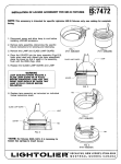
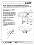
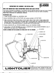
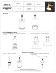
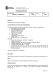
7
-m
-.,
/
INSTRUCTIONSHEETNO.
INSTRUCTIONS
\
IS:6348
FOR INSTALLATION
0383
READ ANO UNDERSTAND THESE INSTRUCTIONS
BEFORE INSTALLING
FIXTURE.
This fixture
is intended
for installation
in accordance
with the National
Electrical
Code
code specifications.
To prevent
electrical
shock, turn off electricity
at fuse box before
1,
Mounting
parts are provided
for switch
(rectangular)
and octagonal
box mounting.
Thread 6-32 STUDS
into RECTANGULAR
OUTLET
BOX in place of box screws.
2
Make connections:
Black fixture
lead or
fixture
lead without
tracer mark to black
supply lead; white fixture
lead or fixture
lead
with tracer mark to white supply lead, Use
WIRE NUTS (local hardware
item). Place
connections
in OUTLET
BOX. Uninsulated
wire is a GROUND
WIRE and must be
connected
to a grounding
terminal
or a
ground
lead in the OUTLET
BOX.
3
Pass BACKPLATE
NUTS provided.
4
After Iamping,
position
GLASS SHADE on
BACKPLATE
and secure
by moving
LEVER
direction
indicated
by arrow.
over
studs
and secure
and local or federal
proceeding.
GLASS SHADE
I
r
I
LUG
/’- ‘ACKPLA
with
in
CAUTION: MAXIMUM WATTAGE AS MARKED
ON FIXTURE MUST NOT BE EXCEEDED.
1A. To mount on an octagonal
box, secure
universal
crossbar
to outlet box with screws
provided
in outlet box.
2A. Make connections:
Black fixture
lead or
fixture
lead without
tracer mark to black
supply lead; white fixture
lead or fixture
lead
with tracer mark to white supply lead. Use
WIRE NUTS (local hardware
item). Place
connections
in OUTLET
BOX. Uninsulated
wire is a GROUND
grounding
terminal
or a ground
lead in the OUTLET
BOX.
3A. Align BACKPLATE
Secure
in place.
over
universal
bar and thread
4A, Lamp and mount glass. After Iamping, position
moving LEVER in direction
indicated
by arrow.
WIRE
and
must
be connected
screw
through
BACKPLATE
into
GLASS
SHADE
on BACKPLATE
to a
universal
bar.
and secure
by