1
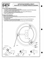
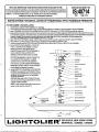
●
READ AND UNDERSTANDTHESEINSTRUCTIONSBEFOREINSTALLINGFIXILfRE
tisfixiure is intended for installation in accordancewiththe NefionalElectricalCodeandlocalregulations.
Jassurefull complianm with local codes and regulations, check with your Iocd electrical inapecfor before
stallation. To prevent elestrfcal shock, turn oft elecfriufy at fuse box before proceeding.
Retain these inatructiona for maintenance reference.
INSTRUCTIONS
FOR
INSTALLATION
OF
TRADITIONAL
STYLE
INSTRUCTION SHEET NO.
IS:40714
1292
RADIANCE
Page 1 of 2
PENDANTS
‘[XTUREASSEMBLY AND INSTALLATION:
1. CarefullyremoveCENTERSTEMASSEMBLY
frompackaging.
2. UnscrewKNURLEDRING from CANOPY LOOP and allow KNURLEO RING and CANOPY to slide down CHAIN to expose CROSSBAR.
3. Mount CROSSBAR and CENTER STEM ASSEMBLY/CHAIN to OUTLET BOX using OUTLET BOX SCREWS (provided with outlet box).
4, Make electrica ccfnnections black ftiure lead or fixture lead without tracer marks to (hot) black supply lea~ white fixhrra lead or fixture lead with trecer mark
to (neutral) white supply lead. Uninsulated wire is a ground and must be attached to GREEN GROUNO SCREW enclosed in CUPPEO WASHER and tightened
in place to ctossbar, then sunnected to grounding terminal or ground lead inside OUTLET BOX. Use WIRENUTS (local hardware item).
CAUTION Push supply wires and wirenut connections back into OUTLkT BOX.
5. Adjust NIPPLE into CROSSBAR to proper CANOPY depth and secure NIPPLE in place by tightening LOCKNUT against CROSSBAR.
B, Slide CANOPY up CHAIN and secare against ceiling by thraadng KNURLED RING onto CANOPY LOOP.
7. Loosen and remove three BATTERY NUTS and STAR WASHERS from MOUNTING STUDS on LOWER FIXFURE ASSEMBLY.
8. Raise LOWER FIXTURE ASSEMBLY to MOUNTING
PLATE on CENTER STEM ASSEMBLY and make
electrical connections Snap together BLACK
9,
-%
FIG. 1
1.1<>
9-I TC>LI
E la” RRiR511wM:E
WITWCTION SHEET NO.
INSTRUCTIONS FOR INSTALLATION OF
TRADITIONAL STYLE RADIANCE PENDANTS CONTINUED
S:40714
!92
Page 2 of 2
JPPORT STEM Attachment
●
AND ADJUSTMEN~
1. Loosen LOWER NUT on end of SUPPORT STEM until it is nearly to the end.
2. Hook opposite end at SUPPORT STEM onto the SUPPORT HOOK on CENTER STEM ASSEMBLY and allow SUPPORT STEM to swing down
so the STEM rest in the SLOT in the SUPPORT BRACKET (Fig. 3A).
3. Tighten LOWER NUT against the SUPPORT BRACKET until SUPPORT STEM draws tight on SUPPORT HOOK (Fig. 3B).
4, Secure in place by tightening UPPER NUT against SUPPORT BRACKET (Fig. 3C).
5. Repeat for remaining SUPPORT STEMS.
IFFUSER CLEANING AND REMOVAL
CAUTION Turn power oft to fixture before attempting to clean.
Diffuser can be cleaned from above the fixture by removing lamps and cleaning DIFFUSER with a soft damp cloth, Should DIFFUSER need to be
removed for cleaning, follow steps below,
1, Remove lamps ~om fixture,’
2, From below fixture, pushup on one side of the DIFFUSER and allow the oppositeside to drop down passed HOLDER KNOB (Fig. 1)
3. Stide DIFFUSER out on an angle from LOWER FIXTURE ASSEMBLY
NOTE DIFFUSER may have to be gentlycompressedon either side to pass fhmugh opening in LOWER FIXTURE ASSEMBLY.
●
I
“Jk
-,
FIG.2
SUPPORT
eRACKET
SUPPORTSTEM
/
UPPERNUT
)WER
NUT
SUPPORTaRACKET
@
(
(
(
SLOT
LOWER
NUT
SUPPORTARM ~
SUPPORTBRACKET
UPPER
NUT
●