1
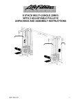
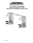
SMITH MACHINE PL06
UNPACKING & ASSEMBLY INSTRUCTIONS
The Smith Machine PL06 comes disassembled. Follow the steps below to assemble it.
WARNING: ASSEMBLING THE SMITH MACHINE PL06 REQUIRES AT LEAST THREE
PEOPLE. COMPONENTS OF THIS MACHINE ARE LARGE AND HEAVY. USE
CAUTION WHEN ASSEMBLING THIS MACHINE.
MATERIALS AND TOOLS REQUIRED FOR UNPACKING AND ASSEMBLY
5/32” Hex
head wrench
1/2”, & 9/16”
Socket
wrench
3/8”, 7/8” &
9/16”
Combination
wrench
Rubber mallet
You will also need a ladder.
ASSEMBLY TIME
Three people can accomplish this assembly in approximately 1 hour.
M051-K50-B101
1
Smith Machine PL06 Unpacking & Assembly Instructions
UNPACKING
Follow the steps below when unpacking the components of the crate. Keep in mind that
the sides of the PL06 are large and heavy. This machine requires three people to uncrate.
1. Remove the shipping wrapper.
NOTE: DO NOT REMOVE THE FOUR HOLLOW TUBE BUMPERS (SHOWN IN
UNPACKING FIGURE 1) UNTIL YOU HAVE COMPLETED ASSEMBLY OF THE PL06.
THESE BUMPERS ARE FOUND ABOVE AND BELOW THE BEARINGS ON THE BAR
CARRIAGES. REMOVAL OF BUMPERS PRIOR TO INSTALLATION OF THE BAR MAY
RESULT IN SEVERE DAMAGE TO THE LINEAR BEARINGS.
Unpacking Figure 1. Leave the hollow tube bumpers until the bar has been installed.
2. Remove the loose parts. Remove all parts other than the sides of the PL06 in the
order shown below:
A. Remove the packaging on the bar carriages as shown in Unpacking Figure 1.
The parts in the box are shown in the back of these instructions in the section
HARDWARE.
B. Starting at the bottom and working upward, remove the packing from the bar. It is
strapped to the plate horns as shown in Unpacking Figure 2. Remove the bar and
set it aside.
2
Smith Machine PL06 Unpacking & Assembly Instructions
Unpacking Figure 2. Remove the bar.
C. Remove the back brace and front brace using a 9/16” socket. They are lagged to
the bottom cross brace board as shown in Unpacking Figure 3.
Unpacking Figure 3. Remove the front and back brace lag screws.
3
Smith Machine PL06 Unpacking & Assembly Instructions
1
2
3
Person 1- Holds right side
Person 2- Holds left side
Person 3- Moves around and assembles
At this stage, three people are required to uncrate the PL06 because the sides are very
heavy and not stable until they are bolted to the front and back braces. Throughout these
instructions, Person 1 refers to the person who holds the right side. Person 2 refers to the
person who holds the left side. Person 3 refers to the person who moves around and
uncrates.
WARNING: THE STEP BELOW REQUIRES THREE PEOPLE. SOMEONE NEEDS TO
BE HOLDING EACH SIDE OF THE PL06 UNTIL THE BACK AND FRONT BRACES
HAVE BEEN SECURED TO THE SIDES. THE SIDES WILL BE LOOSE AND FREE TO
FALL WHEN THE LAG BOLTS FROM THE SHIPPING CRATE HAVE BEEN
REMOVED.
3. Remove the upper shipping board. With Person 1 holding the right side and Person
2 holding the left side, Person 3 will remove the upper shipping board (shown in
Unpacking Figure 4) using a ½” socket wrench. Discard the board, lag bolts, and the
protective fabric scraps.
Unpacking Figure 4. Removing the upper shipping board.
4
Smith Machine PL06 Unpacking & Assembly Instructions
4. Remove the bottom shipping cross brace (with Person 1 holding the right side and
Person 2 holding the left side). The shipping cross brace spans the PL06 as shown
Unpacking Figure 5. Use a 1/2” socket wrench.
Unpacking Figure 5. Shipping cross brace.
6. Remove the bottom shipping boards. WITH PERSON 1 HOLDING THE RIGHT
SIDE AND PERSON 2 HOLDING THE LEFT SIDE, have Person 3 remove the four lag
bolts from the feet as shown in Unpacking Figure 6 using a 1/2” socket wrench. Slide the
boards away from the sides of the PL06.
Unpacking Figure 6. Remove the bottom shipping boards.
5
Smith Machine PL06 Unpacking & Assembly Instructions
7. Slide the left side around the right side and place it four feet away. The sides of
the PL06 are packed reversed from how they will be assembled. Have Person 3 assist in
lifting or sliding the left side (packed on the right) around the other side. Remove the tape
from the PVC support pipes (attached to the bar horns) and pull apart the sides evenly so
that the PVC pipe comes off more easily.
When assembled, the sides will be four feet apart and will appear as shown in Unpacking
Figure 7.
Unpacking Figure 7. Smith Machine PL06 main components.
1.
2.
3.
4.
6
left side
right side
front brace
back brace
5. left bar carriage
6. right bar carriage
7. bar
Smith Machine PL06 Unpacking & Assembly Instructions
ASSEMBLY
1. Attach the front (small) brace. With Person 2 holding the left side and Person 3 holding
the right side, secure the front brace (shown in Assembly Figure 1) by sliding the two
bottom bolts through the bottom holes in the front brace (circled in Assembly Figure 1).
Make sure the Life Fitness nameplate is positioned toward the outside of the machine as
shown in Assembly Figure 1. The two bolts have already been inserted through the sides
of the PL06. Tighten these two bolts to stabilize the PL06. Loosely tighten the nuts on the
bolts to make attaching the back brace easier.
Insert two 4-1/4” bolts into the top two holes from the outside of the machine and loosely
tighten them. The flat washers and end cap washers need to go onto the bolts in the top
holes using the configuration shown in Assembly Figure 2.
Assembly Figure 1. Attach the front brace.
NOTE: The two lower bolts on the front brace will NOT have washers or
end caps on the head of the bolt.
Assembly Figure 2. Bolt, flat washer, nut, end cap washer and end cap configuration
(typical for both 4” and 4-1/4” bolts).
7
Smith Machine PL06 Unpacking & Assembly Instructions
2. Attach the back (large) brace. Insert the back brace with the warning label facing inward
(circled on right in Assembly Figure 3) by first placing the two 4” bolts into the top holes of
the sides as shown in Assembly Figure 3. On the back brace, the bolts go on from the
inside of the machine. Put the four 4-1/4” bolts into the four remaining holes. Tighten the
back brace securely using a 9/16” socket and box wrench.
NOTE: YOU MAY NEED TO USE A MALLET TO FORCE THE BOLTS ON
THE BACK BRACE THROUGH THE FRAME OF THE PL06.
ADDITIONALLY THE BAR HORNS MAY BE BOWED OUTWARD
REQUIRING A SECOND PERSON TO HOLD THEM IN WHILE
SOMEONE TIGHTENS THE BOLTS.
Assembly Figure 3. Attach the back brace with label (circled right) facing inward.
3. Tighten the bolts on the front brace. Tighten the four bolts on the front brace using a
9/16” socket and box wrench.
4. Put end caps on all the bolt heads and the nuts. Snap the end caps (part number C in
Hardware Figure 1) onto the end cap washers.
8
Smith Machine PL06 Unpacking & Assembly Instructions
Assembly Figure 5. Remove the right bar carriage.
5. Remove the right bar carriage. Have one person take the bar carriage and pull it down
from the top of the PL06. This person will also need to hold down the cable that the
carriage is bolted onto. Have a second person remove the carriage by loosening the eight
bolts (shown in Assembly Figure 5) using a 3/8” combination wrench and a 5/32” hex key
wrench. You may also remove the bar carriage entirely by removing the cable jam nuts
shown in Assembly Figure 8.
6. Insert the bar into the right side carriage. Swing the carriage out by pulling down on
the cable and slide the bar into the right side carriage. Make sure the bar hooks are
positioned upward as shown in Assembly Figure 6. Insert the bar carriage into the bar
hook as shown in Assembly Figure 6 to hold the bar in place. Retighten the eight bolts
inserting a washer under the bolt.
Assembly Figure 6. Insert the bar into the right carriage and place on bar hook.
9
Smith Machine PL06 Unpacking & Assembly Instructions
7. Insert the bar into the left side carriage. Repeat Steps 5 and 6 above for the left side
carriage. Remove the carriage bolts and slide the left bar carriage onto the bar and
secure it to the sliders. Loosely tighten the hex cap screws using a 5/32” hex key and 3/8”
combination wrench.
8. Secure the cables to the carriages. The cables are attached with cable nuts (see
Assembly Figure 8). Hold the bar on your shoulder as shown in Assembly Figure 7 and
twist it out of the hook plate. With the bar around chest height (or lower), use a 7/8”
combination wrench to tighten the cable nuts to the cables as shown in Assembly Figure
8.
Assembly Figure 7. Remove the bar from the hook plate.
Assembly Figure 8. Tighten upper and lower cable nuts.
Repeat this step for the other side of the carriage.
10
Smith Machine PL06 Unpacking & Assembly Instructions
9. Tighten the bolts on the carriage. Using a 5/32” hex head driver and 3/8” combination
wrench, securely tighten the eight hex head bolts on each bar carriage. Bar adjustments
may be made by loosening the carriage bolts and tightening them one at a time in the
order shown in Assembly Figure 9 below. Start in the top right corner and move to the
bottom left corner. Continue the pattern of top left to bottom right as shown in Assembly
Figure 9.
3
1
8
5
7
2
6
4
Assembly Figure 9. Carriage bolt tightening pattern.
BAR SPACERS
The PL06 includes plastic bar spacers that should be inserted between the bar and the bar
carriages if there is extra play in the bar. The spacers are cut so that they can be easily
slipped over the bar. Insert one on each side of the bar as shown in Assembly Figure 10.
Assembly Figure 10. Bar spacers.
11
Smith Machine PL06 Unpacking & Assembly Instructions
HARDWARE
The parts bag holds the nuts, bolts, washers, end cap washers, and end caps. These are
shown below.
½
0
½
1
½
½
2
3
½
4
½
5
6
A
B
C
D
E
F
Hardware Figure 1. Back and Front Brace Parts.
The parts shown in Hardware Figure 1 are used to bolt the front and back braces to the
Smith Machine PL06. They are:
A. 4-1/4” Hex head bolt (used to bolt the front and back supports to the sides) (6)
B. 4” Hex head bolt (used as the top bolt on the back support) (2)
C. End caps (bolt covers) (20)
D. Flat washer (used to “shorten” bolt so end cap will fit on the nut) (10)
E. End cap washers (end caps snap onto them) (20)
F. 3/8” Locknut (10)
12
Smith Machine PL06 Unpacking & Assembly Instructions
PARTS ORDER LIST
Use the list below if you need to order parts from Life Fitness.
Part #
ID
Description
Quantity
Assembled sides
Front (small) brace
Back (large) brace
Bar carriages (attached to
cables on sides)
Bar
2
1
1
2
4-1/4” hex head bolt
4” hex head bolt
End caps
Flat washer
End cap washers
3/8” locknut
6
2
20
10
20
10
#10-24 x 1” Hex cap screw
Hex cap washer
Hex key nut
16
16
16
Cable jam nut
4
Pillow block sliders
4
Plastic bar spacers
2
Main components
1 and 2
3
4
5 and 6
7
1
Front and back
brace hardware
0017-00101-1567
0017-00101-1420
0017-00042-0969
0017-00104-0313
0017-00104-0368
0017-00103-0217
A
B
C
D
E
F
Carriage hardware
0017-00101-1569
0017-00104-0312
0017-00103-0227
Cable hardware
0017-00103-0234
Carriage hardware
0017-00006-0180
Bar spacers
PL06 MOU50-0000
13