1
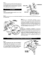
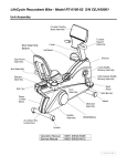
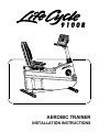
AEROBIC TRAINER
INSTALLATION INSTRUCTIONS
Congratulations...
and welcome to the world of
and the Lifecycle 9100R
aerobic trainer.
The following Parts Identification Listing and the step by step installation
procedures have been assembled to make the set-up of your aerobic trainer as
quick and easy as possible.
Please take special note of the following important points prior to choosing a
location and beginning assembly of the Lifecycle exercise bike…
SAFETY FIRST!
⇒
DO NOT locate the Lifecycle 9100R aerobic trainer outdoors, near swimming pools, or in
areas of high humidity.
⇒
DO NOT operate your Lifecycle 9100R aerobic trainer if it has been dropped, damaged, or
even partially immersed in water. Contact Life Fitness Customer Support Services at the
number on the back page of this Installation Instruction Guide.
⇒
DO NOT locate the Lifecycle 9100R aerobic trainer any closer than 30 inches ( 76 cm ) to a
television set.
⇒
DO keep the area around your Lifecycle 9100R aerobic trainer clear of any obstructions,
including walls and furniture.
⇒
DO verify the contents of the delivery carton against the accompanying Parts Listing prior to
setting the cartons and shipping material aside. If any parts are missing, contact Life Fitness
Customer Support Services at the number listed on the back page of this Installation
Instruction Guide. Save the shipping cartons in case of return.
⇒
DO read the entire Operation Manual prior to attempting to operate this machine as this is
essential for proper use.
TOOLS REQUIRED FOR ASSEMBLY... Phillips screwdriver, 1/2” wrench, 5/32” hex key wrench
PARTS DESCRIPTION
1
3
5
7
9
11
Seat Back Screw
0017-00101-1131
Handlebar Bolt
0017-00101-0986
Seat Back
0K19-01078-0000
Handlebar Assembly
AK19-00035-0000
9V Alkaline Battery
0017-00003-0573
Qty. 4
2
Qty. 2
4
Qty. 1
6
Qty. 1
8
Qty. 1
10
12
Seat Back Washer
0017-00104-0253
Console Screw
0017-00101-1104
Collar
0K19-01125-0000
Display Console
AK19-00114-0001
Qty. 4
Qty. 4
Qty. 1
Qty. 1
Step 1
Align the four holes in the SEAT BACK (#5) with those in
the SEAT BACK POSTS. Insert the four SCREWS (#1)
and WASHERS (#2) through the backside of the SEAT
BACK POSTS and into the SEAT BACK. Tighten the
four SCREWS with a hex key wrench.
NOTE: BE CAREFUL NOT TO OVER-TIGHTEN
THE SCREWS.
Step 2
Unfold the CONSOLE WIRE HARNESS from the POST
extending from the FRAME.
Step 3
Slide the COLLAR (#6) onto the HANDLEBAR ASSEMBLY (#7) with the angled side of the COLLAR facing toward
the HANDLEBAR.
Step 4
While holding the HANDLEBAR ASSEMBLY (with the
COLLAR in place) in one hand, feed the WIRE HARNESS
at the top of the FRAME POST through the bottom of the
HANDLEBAR ASSEMBLY COLUMN, as shown, with your
other hand. Continue pushing the WIRE HARNESS until the
CONNECTOR at the end of the WIRE HARNESS exits
through the opening at the top of the COLUMN. Gently pull
the WIRE HARNESS to remove the slack.
Step 5
Position the HANDLEBAR ASSEMBLY so that the
HANDLEBAR is facing the user and slide the HANDLEBAR
ASSEMBLY into the FRAME POST while being careful not
to pinch the WIRES in the process. Align the holes in the
bottom of the HANDLEBAR ASSEMBLY with those in the
FRAME POST. (Both the HANDLEBAR ASSEMBLY and the
FRAME POST are keyed to ease the alignment and
positioning). Install the two HANDLEBAR BOLTS (#3) to
secure it into position.
NOTE: BE VERY CAREFUL NOT TO DAMAGE THE WIRES WHEN PASSING THE BOLTS
THROUGH THE HOLES. TIGHTEN THE BOLTS SECURELY.
Step 6
There is a large hole in the rear of the DISPLAY
CONSOLE (#8) through which you can see a 16-PIN
CONNECTOR. This corresponds to the matching
WIRE HARNESS CONNECTOR protruding from the
top of the HANDLEBAR ASSEMBLY. Properly align
the LOCKING TABS of the 16-PIN CONNECTORS
and plug them together until they SNAP into place.
Step 7
Carefully feed the wire back into the top of the HANDLEBAR
ASSEMBLY and attach the DISPLAY CONSOLE to the
HANDLEBAR ASSEMBLY using the four CONSOLE SCREWS
(#4) and a phillips screwdriver. Tighten the four SCREWS in a
criss-cross pattern.
NOTE: BE CAREFUL NOT TO OVERTIGHTEN THE
SCREWS.
Step 8
To install the 9-VOLT ALKALINE BATTERY (#9) found in the parts bag use a Phillips screwdriver to remove the
screw from the back door. Gently pull the BATTERY WIRES from the back of the DISPLAY CONSOLE and connect
them to the 9-VOLT ALKALINE BATTERY. Carefully, tuck the BATTERY WIRES back into the DISPLAY
CONSOLE and set the BATTERY in place.
Re-install the BATTERY DOOR by inserting the bottom tab of the BATTERY DOOR into the corresponding slot in
the DISPLAY CONSOLE. Push the DOOR into place and tighten the screw with a Phillips screwdriver.
NOTE: ONLY USE AN ALKALINE TYPE BATTERY. USE OF ANY OTHER TYPE BATTERY
MAY RESULT IN A MALFUNCTION OR DAMAGE.
CAUTION!: BE CAREFUL NOT TO OVER TIGHTEN THE SCREW
Step 9
Slide the COLLAR (#6) down until it completely covers the HANDLEBAR ASSEMBLY HARDWARE and the POST
extending up from the FRAME. Secure the COLLAR by “pinching” in the sides and pushing down firmly. The
COLLAR will lock into place.
Step 10
After placing the Lifecycle in the intended location for use,
check the stability of the bike. If the Lifecycle is not level, turn a
LEVELER in the rear STABILIZER BAR in either direction until
the rocking motion diminishes.
NOTE: ONLY ONE LEVELER NEEDS TO BE TURNED.
OPERATION CHECKLIST
⇒ Insure that the STABILIZER BAR and HANDLEBAR BOLTS are tight.
⇒ Make sure the aerobic trainer is properly leveled and stable.
⇒ Read the entire Operation Manual before using the trainer.
English/Metric Default Setting Toggle
The default setting of the Lifecycle 9100R aerobic trainer display console is set to English units of measurements at the
factory. If your display console will require units of measurements to be in metric, it may be necessary to change the
setting from English to metric. To do so, you will need to enter into the diagnostic programs and proceed to Diagnostic
State 8. To do so, follow the instructions as listed below.
Press and continue to hold the ‘5’ key on the keypad and then press ‘START’ while pedaling the bike over 55 RPM.
On entry, all LED’s and 7-segment displays will be on. You are now in Diagnostic State 1. Press the START/ENTER
key seven times to forward to diagnostic state 8 and choose the default setting.
In ALL DIAGNOSTIC STATES, the user must keep pedaling the bike. If the pedal RPM drops too low, the bike will shut
down, requiring at least 40 RPM or greater and a START switch closure to operate again.
Diagnostic State 8:
This test indicates the display console default setting of English or metric units of measurements.
When the default is set to English units of measurements, it will read ‘ E ’ in the DATA ENTRY WINDOW.
When the default is set to metric units of measurement, it will read ‘ 9 ’ in the DATA ENTRY WINDOW.
The user can change the default setting of the system by pressing the ' 5 ' key. The system will toggle from an ‘ E ’ to ‘
9 ’ to ‘ E ’ condition by continuing to press the ' 5 ' key.
Diagnostic State 7 can be entered now by pressing the CLEAR/PAUSE key and you can continue going backwards by
pressing the CLEAR/PAUSE key through previous diagnostics until you return to the user display.
Before attempting to operate your Lifecycle 9100R trainer, it is imperative that you familiarize yourself with the contents
of the Operation Manual. If your aerobic trainer does not respond as described in the OPERATION MANUAL contact:
Life Fitness Customer Support Services
at (800) 351-3737 or (847) 451-0036
Prior to your call, please be sure you have located and noted the MODEL NUMBER & SERIAL NUMBER.
The Model & Serial number information of your Life Fitness 9100R aerobic trainer is contained in a label located under
the center of the front stabilizer bar.
Copyright 1996 Life Fitness. All rights reserved. The Life Fitness trademark is registered in the U.S. Patent and Trademark Office, Certificate
No. 1,400,502 issued July 8, 1986. Lifepulse and Zone Trainer are registered trademarks of Life Fitness. Any use of these trademarks, without
the express written consent of Life Fitness is forbidden. U.S. Patent Numbers 3,767,195 and 4,358,105.
M051-00K19-A045
5-96