1
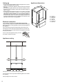
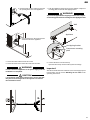
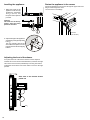
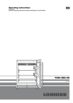
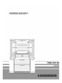
Setting up
• Avoid positioning the appliance in direct sunlight or near cookers,
radiators and similar sources of heat.
• The floor on which the appliance stands should be horizontal
and level.
• The ventilation grilles should not be obstructed. Always ensure
that there is good ventilation and that the outward flowing air is
able to escape.
• Standard EN 378 specifies that the room in which you install
your appliance must have a volume of 1 m³ per 8 g of R 600a
refrigerant used in the appliance, so as to avoid the formation of
inflammable gas/air mixtures in the room where the appliance
is located in the event of a leak in the refrigerant circuit. The
quantity of refrigerant used in your appliance is indicated on the
type plate on the inside of the appliance.
Electrical connection
Only operate the appliance with alternating current (AC).
The permissible voltage and frequency are indicated on the type
plate. The position of the type plate is shown in the description of
the appliance.
The socket must be properly earthed and protected by a fuse.
The tripping current of the fuse must be between 10 A and 16 A.
The socket must not be situated behind the appliance and must
be easily accessible.
Do not connect the appliance using an extension cable or extension socket.
Appliance venting
The required air flow is directed through the plinth.
It is important to use the provided ventilation grille for the ventilation opening.
This opening must not be covered.
12
Appliance dimensions
A = 76 mm
B = 2027 mm
C = 910 mm
D = 76 mm
E = 910 mm
G = 1078 mm
H = 943 mm
GB
Installation dimensions
The socket must be positioned within the areas marked in grey or
above the installation recess.
The ice maker is fitted in the freezer compartment of the combined
refrigerator-freezer. It must be connected to the mains water supply to work.
The water shut-off valve must be positioned within the areas
marked in grey.
WARNING!
The water shut-off valve must not sit directly above the
socket!
The gap between the water shut-off valve and the socket
must comply with the regulations of the country in which
the appliance is used!
13
Mounting the anti-tipping device
WARNING!
The supplied anti-tipping bracket must be installed in all
cases. This prevents the appliance from tipping over when
the fully loaded door is opened.
Installation:
1. Mark the centre line of the appliance on the floor.
Align the anti-tipping bracket centre to the centre line.
CAUTION!
Ensure that there are no electric cables or water pipes in the
wall section to which the anti-tipping bracket is to be secured.
These could be damaged during installation.
2. Secure the anti-tipping bracket to the floor using the 3 screws
(6 mm x 60 mm) included in the accessory pack.
The distance between the leading edge of the body of the unit
and the rear edge of the anti-tipping bracket is 610 mm.
Important!
When securing the anti-tipping bracket to a concrete floor,
use suitable plugs!
If the floor slopes down sideways, the anti-tipping
bracket must be fitted horizontally. Lay down spacers
in the appropriate positions.
Wall
Connection to the water supply
Safety instructions and warnings
• Do not connect to the water supply while the combined refrigeratorfreezer is connected to the electricity supply.
• The connection to the mains water supply may only be
made by trained personnel.
• The water quality must comply with the drinking water
directives of the country in which the appliance is used.
• The ice maker is designed exclusively to make ice cubes in
quantities required by a household and may only be operated
with water suitable for this purpose.
• All repairs and work on the ice maker may only be carried out by
customer service personnel or other trained personnel.
• The manufacturer cannot accept liability for damage caused
by a faulty connection to the mains water supply.
Water pressure
The water pressure must be between 0.15 and 0.6 MPa (1.5 6 bar).
Important:
If the water filter is inserted in the appliance, the water
pressure must lie between 0.3 and 0.6 MPa (3 - 6 bar).
If the water pressure with the inserted water filter is too low,
this may cause the ice maker to malfunction.
The water supply to the appliance must be through a cold
water pipe that can withstand
the operating pressure and
complies with the hygiene
regulations. For this, use the
stainless steel hose supplied
(length 3 m).
Installation
1. Place the appliance in front of the installation recess.
2. Apply cover strips on the side
walls of the appliance.
14
GB
3. Insert the bent section of the hose through
the opening at the rear of the appliance.
7. Push the appliance slowly into the recess until the compressor
mounting plate touches the anti-tipping bracket.
WARNING!
To prevent the appliance from tipping forwards, the compressor mounting plate must be touching the anti-tipping bracket!
Wall
Appliance
4. Connect the hose to the solenoid valve
at the front side of the appliance.
Anti-tipping bracket
Compressor mounting
plate
5. Route the mains cable towards the socket.
6. Route the water hose towards the water shut-off valve.
WARNING!
Do not connect the appliance to the power supply until the
installation is completed.
CAUTION!
8. Connect the hose to the shut-off tap.
Open the shut-off tap and check the system for leakage.
Important!
After the ice maker has been switched on, the water supply system
must be bled. See the section Bleeding the ice maker in the
operating instructions.
Lay the mains cable and the water hose in such a way that
they will not be damaged when the appliance is slid into
the installation recess.
5.
6.
15
Levelling the appliance
1. Adjust the height of the
appliance at the front by
twisting the adjustable
feet
(A/F 27). Use
the open-ended spanner
provided.
Fasten the appliance in the recess
Fasten the appliance in the recess through the upper and lower
hinges of the refrigerator doors.
Use 2 screws for each hinge.
1
Caution!
The front feet of the appliance must be firmly
placed on the floor.
screws
(4 x 16 mm)
2. Adjust the height of the appliance
at the rear by turning the adjusting
bars
.
2
Turn the adjusting bars clockwise until the compressor mounting plate touches the anti-tipping
bracket.
Adjusting the front of the drawer
If required, the front of the freezer drawers can be adjusted.
Transfer the screws shown in the illustration (on the left and right
sides of the freezer drawer) individually to the long slots below.
Tighten the screws in the front of the drawer once it is in the right
position.
Side view of the freezer drawer
pulled out
16
Before fitting the door panels
Remove the cover
and unscrew the attachment bracket
from the refrigerator doors. These attachment brackets will be
mounted onto the refrigerator door panels.
1
2
Important!
The securing nuts are needed for re-mounting the preassembled door panels onto the refrigerator doors.
Panel dimensions
GB
Min. panel thickness = 16 mm
Max. panel thickness = 19 mm
Maximum panel weight
Refrigerator panel = 27 kg
Freezer drawer panel = 10 kg
Unscrew the attachment brackets
from the freezer drawers.
These attachment brackets will be mounted onto the freezer panels.
3
Important!
The screws are needed for re-mounting the pre-assembled
freezer panels onto the freezer drawers.
17
Mounting the attachment brackets onto the door panels
Mark lines on the refrigerator door panels as shown in Fig. A.
Align the dismounted brackets of the refrigerator doors to the lines on the refrigerator door panels as shown in Fig. A 1. Fasten each
bracket with any hole wherever possible using a minimum of 6 screws 4 x 16 mm.
Fasten the brackets provided onto the freezer drawer panels using three screws (4 x 16 mm) for each bracket (Fig. A2).
Refrigerator door panels
Fig. A 1
Freezer drawer panel
Fig. A 2
Freezer drawer panel
Fig. A
18
Fig. A 2
Mounting the refrigerator panel
The description is for one panel only. The procedure is the same
for both panels.
1. Open the refrigerator door and suspend the refrigerator panel
on the top adjusting pins (fig. B).
GB
To make it possible to fasten the refrigerator panel at the bottom
the soft-stop cylinder must be dismantled.
5. Stick a small screwdriver under the retaining clamp and lever
out (fig. D).
2. Screw securing nuts onto the adjusting pins and slightly tighten
(fig. B).
fig. D
6. Grasp the soft-stop cylinder and pull down (Fig. E).
The soft-stop cylinder retracts in the detached state.
fig. B
3. Close the refrigerator door and check the height of the panel.
4. Adjust the height of the panel if necessary. Undo the securing
nuts and use the adjusting pins to adjust (fig. C).
fig. E
7. Transfer the lower edge of the attachment bracket onto the panel
using a pencil. (fig. F). Remove the panel from the refrigerator
door.
fig. C
fig. F
19
8. Dismantle the lower attachment bracket from the refrigerator
door. Align the bracket to the lines on the refrigerator door
panel. (fig. G).
Fasten the bracket with any hole wherever possible using a
minimum of 6 screws 4 x 16 mm.
13. Fasten the refrigerator panel using the same screws that
held the lower bracket before removal (fig. K).
fig. K
fig. G
14. Extend the soft-stop cylinder and connect with the ball stud
(fig. L).
9. Open the refrigerator door and suspend the refrigerator panel
on the top adjusting pins (fig. H).
10. Screw securing nuts onto the adjusting pins and slightly tighten
(fig. H).
fig. L
fig. H
15. Attach the retaining clamp to the ball housing of the soft-stop
cylinder (fig. M).
11. Move the panel to the left until it makes contact with the center
rail (fig. I).
12. Tighten the hex nuts finally.
fig. M
fig. I
20
Mounting the dust filter
16. Click cover into place (fig. N).
GB
The supplied dust filter prevents that dirt enters the motor compartment, reducing the refrigeration performance. Therefore always
install the dust filter.
1. Pull the bottom freezer drawer right out.
2. Remove the protective film from the dust filter. Insert the filter at
the bottom, press the button down and click the filter into place.
fig. N
Mounting the freezer panels
1. Pull out the top freezer drawer and screw on the pre-assembled
panel. The same screws must be used as those used to screw
on the attachment brackets (3.5 x 13).
2. Close the freezer drawer and check the position of the panel.
Adjust the height of the panel by undoing the left and right
screws. Tighten the screws.
3.Pull out the bottom freezer drawer and mount the panel in the
same way.
Mounting the ventilation grille
Important!
To ensure fault-free operation of the appliance, you must
install the supplied ventilation grille.
Do not obstruct the ventilation opening or cover it with a panel!
4. For both drawers, cover the gap between the drawer and the
panel with the cover strips supplied. Remove the protective
film from the trim and insert into the gap at the top.
3.5 x 13 mm
21
Liebherr Hausgeräte Lienz GmbH * Dr.-Hans-Liebherr-Strasse 1 * A-9900 Lienz ** www.liebherr.com