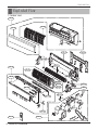
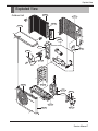
1
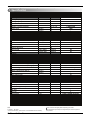
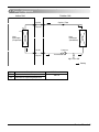
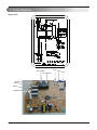
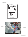
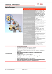
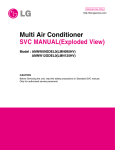
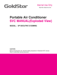
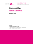
http://biz.lgservice.com
Room Air Conditioner
SVC MANUAL(Exploded View)
MODEL : TS-C1825DA1
CAUTION
Before Servicing the unit, read the safety precautions in General SVC manual.
Only for authorized service personnel.
1. Specification
Product Model
Sales Model
Capacity
Cooling Capacity
Heating Capacity
Electrical Parts
Voltage. Frequency/Phase
Power Input
Running Current
Performance
EER
COP
Air Circulation
Moisture Removal
Sound Level
Feature
Neo Plasma Air Purifying System
Anti Corrasion
Temperature Control
CHAOS Wind(Auto Wind)
Airflow Direction Control(up&down)
Airflow Direction Control(left&right)
Remocon Type
Setting Temperature Range
TS-C1825DA1
SJ182CD
Btu/h
Btu/h
Φ / V / Hz
W
W
A
A
Cooling
Heating
Cooling
Heating
Cooling
Heating
Indoor,Max
Outdoor,Max
Btu/h
W/W
㎥/min(cfm)
㎥/min(cfm)
l/h
dB(A)+3
dB(A)+3
Indoor,H/M/L
Outdoor,Max
Cooling
Heating
10.0
13.0
28
2.5
42
56
o
1 C
7Hr,Off
Y
3
Y
Rotary,PH250(Toshiba)
Type
WxHxD
Indoor/Outdoor
With S/parts
Without S/parts
Note:
O : Applied, - : No relation
* For circuit breaker rating, please conform to local standards wherever necessary.
2 Room Air Conditioner
1,220V,60Hz
1800
8.4
-
N
N
Y
N
Auto
Manual
Wireless Simple
18-30
N
N
3/4
Auto Chage Over
Auto Clean
Seps,Fan/Cool
Temperature Increment
Timer
Sleep Operation
Restart Delay(Minute)
Hot start
Jet Cool
Compressor
Installation & Stuffing
Net Dimensions
Net Weight
Q'ty
18000
-
mm
kg
20/40FT
20/40FT
1090*314*190/770*540*245
14/41
Some of functions are slightly different depending upon models.
The specification may be subject to change without prior notice for purpose of
improvement.
2. Piping Diagrams
Indoor Unit
Outdoor Unit
Liquid Side
Capillary Tube
2-Way Valve
Th2
Th1
Heat
Exchanger
(Evaporator)
Heat
Exchanger
(Condenser)
Compressor
Gas Side
3-Way Valve
Accumulator
High Pressure S/W
Cooling
LOC.
Description
Th1
Thermistor for indoor air temperature
Th2
Thermistor for evaporating temperature
PCB Connector
CN-TH1
Service Manual 3
3. Wiring Diagrams
BL
GN/YL
BR
Indoor Unit
GN/YL
BL
BR
1(L)2(N) 3
3854A23009
RY-COMP
RY-COMP4
FUSE
CN-N2
CN-N1
CN-MOTOR
4 Room Air Conditioner
CN-U/D
CN-HVB
CN-DISP2
Outdoor Unit
BLUE
RED
BLUE
S
R
CAPACITOR
H
C
F
RED
BLUE
OVERLOAD
PROTECT
C
YELLOW/GREEN
BLUE
BROWN
YELLOW
FAN
BLUE
BROWN
TERMINAL BLOCK 1(L) 2(N)
THE UNIT INDOOR
OUTDOOR DIAGRAM WIRING
EBY36312302
Capacitor
Terminal Block
Service Manual 5
Exploded View
Exploded View
1. Indoor Unit
135316
152302
135313
131410
733010
342800
359011
135311
354210
147581
352115
346810
35211B
352116
268711A
352150
135516
268711D
W0CZZ
146811
267110
6 Room Air Conditioner
249951
Exploded View
Exploded View
Outdoor Unit
554031
437212
552112
435512
552111
649950
549610
435511
559010
546810
435301
447910
554160
552203-1
550140
430410
437210
552203-2
Service Manual 7
P/NO : MFL37322726
JANUARY, 2008