1
Model number :
Serial number :
P/NO : 3828VA0484E (RF04FA)
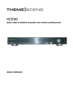
PLASMA MONITOR
Please read this manual carefully before operating your set.
Retain it for future reference.
Record model number and serial number of
the set.
See the label attached on the back of the set
and quote this information to your dealer when
you require service.
MW-71PY10
MW-71PY10G
OWNER’S MANUAL
Safety Instructions
Safety Instructions
* Safety instructions have two kinds of information, and each meaning of it is as below.
WARNING The violation of this instruction may cause serious injuries and even death.
NOTES
The violation of this instruction may cause light injuries or damage of the
product.
Take care of danger that may happen under specific condition.
WARNING
W
1. Do not place the product in direct sunlight or near
heat sources such as heat registers, stove and so on.
8. Do not place heavy objects on the product.
This may cause serious injury to a child or adult.
This may cause a fire.
9. Do not use water the product while cleaning.
2. Do not use the product in damp place such as a
bathroom or any place where it is likely to get wet.
This may cause damaged the product or could give an electric shock.
This may cause a fire or could give an electric shock.
3. Bend antenna cable between inside and outside
building to prevent rain from flowing in.
This may cause water damaged inside the product and could
give an electric shock.
This may cause a fire or could give an electric shock.
11. Do not attempt to service the product yourself.
Contact your dealer or service center.
4. Earth wire should be connected.
- If the earth wire is not connected, there is possible a danger
of electric shock caused by the current leakage.
- If grounding methods are not possible, a separate circuit
breaker should be employed and installed by a qualified
electrician.
- Do not connect ground to telephone wires, lightning rods or
gas pipe.
5. Do not placing anything containing liquid on top
of the product.
Power
supplier
Short-circuit
breaker
This may cause a fire or could give an electric shock.
6. Wet Location Marking :
Apparatus shall not be exposed to dripping or splashing and
no objects filled with liquids, such as vases, shall be placed
on the apparatus.
7. Do not insert any object into the exhaust vent.
This may cause a fire or could give an electric shock.
2 Plasma Monitor
10. In case of smoke or strange smell from the product, switch it off ,unplug it from the wall outlet
and contact your dealer or service center.
This may cause damaged the product or could give an electric shock.
12. During a lightning thunder, unplug the product
from the wall outlet and don’t touch an antenna
cable.
This may cause damaged the product or could give an electric shock.
Safety Instructions
ENGLISH
NOTE
1. Never touch the power plug with a wet hand.
This may cause an electric shock.
8. Ensure the power cord doesn’t trail across any
hot objects like a heater.
This may cause a fire or an electric shock.
2. Disconnect from the mains and remove all connections before moving.
3. Do not place the product in a built-in installation
such as a bookcase or rack.
9. Do not plug when the power cord or the plug is
damaged or the connecting part of the power outlet is loose.
This may cause a fire or an electric shock.
Ventilation required.
10. Dispose of used batteries carefully to protect a
child from eating them.
In case that it eats them, take it to see a doctor immediately.
11. When moving the product assembled with speakers do not carry holding the speakers.
This may cause the product to fall, causing serious injury to a
child or adult, and serious damage to the product.
4. When installing the product on a table, be careful
not to place the edge of its stand.
This may cause the product to fall, causing serious injury to a
child or adult, and serious damage to the product.
12. Unplug this product from the wall outlet before
cleaning. Do not use liquid cleaners or aerosol
cleaners.
This may cause damaged the product or could give an electric shock.
13. Contact the service center once a year to clean
the internal part of the product.
Accumulated dust can cause mechanical failure.
14. The distance between eyes and the screen should
be about 5 ~ 7 times as long as diagonal length of
the screen.
If not, eyes will strain.
5. Do not place an outside antenna in the vicinity of
overhead power lines or other electric light or
power circuits.
This may cause an electric shock.
6. There should be enough distance between an outside antenna and power lines to keep the former
from touching the latter even when the antenna
falls.
15. Unplug the product from the wall outlet when it is
left unattended and unused for long periods of
time.
Accumulated dust may cause a fire or an electric shock from
deterioration or electric leakage.
16. Only use the specified batteries.
This make cause damaged the product or could give an electric shock.
This may cause an electric shock.
7. Do not pull the cord but the plug when unplugging.
This may cause a fire.
Owner’s Manual 3
Safety Instructions
Safety Instructions continued
CAUTION concerning the Power Cord :
Most appliances recommend they be connected to a dedicated circuit; that is, a single outlet circuit which
powers only that appliance and has no additional outlets or branch circuits. Check the specification page
of this owner's manual to be certain.
- This may cause a fire or an electric shock.
Do not overload wall outlets. Overloaded wall outlets, loose or damaged wall outlets, extension cords, frayed
power cords, or damaged or cracked wire insulation are dangerous. Any of these conditions could result in electric shock or fire. Periodically examine the cord of your appliance, and if its appearance indicates damage or deterioration, unplug it, discontinue use of the appliance, and have the cord replaced with an exact replacement part
by an authorized servicer.
Protect the power cord from physical or mechanical abuse, such as being twisted, kinked, pinched, closed in a door,
or walked upon. Pay particular attention to plugs, wall outlets, and the point where the cord exits the appliance.
Use a dedicated power cord. Do not modify or extend the power cord.
Do not install, remove, or reinstall the unit by yourself (customer).
For electrical work, contact the dealer, seller, a qualified electrician, or an Authorized Service Center. For installation, always contact the dealer or an Authorized Service Center.
Do not use if the power cord or plug is damaged, or socket is loose. Use a dedicated outlet for this appliance.
Do not over bend the power cord and do not place anything on the power cord. Do not install the monitor near any
sharp edge to avoid wire damage.
Safety instruction (MW-71PY10G only)
When the trim becomes dirty or stained, softly polish the surface.
When polishing the surface, use gentle pressure. Heavy pressure can damage or discolor the surface.
Clean the surface quickly and use gentle pressure. Heavy pressure can damage or discolor the surface.
Keep the alcohol and the used cleaning towel out of the reach of children.
Do not use anything to scrape or scratch at the surface of this unit, this will cause damage to the surface.
Use soft gloves while installing or removing this unit to prevent damaging the surface.
4 Plasma Monitor
Contents
Contents
Introduction
Controls and Connection Options . . . . . . . . . .7~8
Remote Control Key Functions . . . . . . . . . . . . . .9
Installation
Installation . . . . . . . . . . . . . . . . . . . . . . . . . . . . . .10
Installation Instruction . . . . . . . . . . . . . . . . . . . . . .11
External Equipment Connections . . . . . . . . . .12~17
VCR Setup . . . . . . . . . . . . . . . . . . . . . . . . . . . .12
Cable TV Setup . . . . . . . . . . . . . . . . . . . . . . . .13
External A/V Source Setup . . . . . . . . . . . . . . . .13
DVD Setup . . . . . . . . . . . . . . . . . . . . . . . . . . . .14
DTV Setup . . . . . . . . . . . . . . . . . . . . . . . . . . . .14
PC Setup . . . . . . . . . . . . . . . . . . . . . . . . . .15~16
HDMI . . . . . . . . . . . . . . . . . . . . . . . . . . . . . . . .17
Operation
Turning on the Monitor . . . . . . . . . . . . . . . . . . . . .18
Menu Language Selection . . . . . . . . . . . . . . . . . .18
Picture Menu Options
APC (Auto Picture Control) . . . . . . . . . . . . . . . .19
XD . . . . . . . . . . . . . . . . . . . . . . . . . . . . . . . . . .19
Auto Color Temperature Control . . . . . . . . . . . .19
Fleshtone . . . . . . . . . . . . . . . . . . . . . . . . . . . .20
sRGB . . . . . . . . . . . . . . . . . . . . . . . . . . . . . . .20
Manual Picture Control . . . . . . . . . . . . . . . . . .20
Sound Menu Options
DASP (Digital Auto Sound Processing) . . . . . . .21
Manual Sound Control . . . . . . . . . . . . . . . . . . .21
BBE . . . . . . . . . . . . . . . . . . . . . . . . . . . . . . . . .21
AVL (Auto Volume Leveler) . . . . . . . . . . . . . . . .21
Timer Menu Options
Clock Setup . . . . . . . . . . . . . . . . . . . . . . . . . . .22
On/Off Timer Setup . . . . . . . . . . . . . . . . . . . . .22
Auto Off . . . . . . . . . . . . . . . . . . . . . . . . . . . . . .22
Sleep Timer . . . . . . . . . . . . . . . . . . . . . . . . . . .22
Special Menu Options
Key Lock . . . . . . . . . . . . . . . . . . . . . . . . . . . . .23
ISM Method . . . . . . . . . . . . . . . . . . . . . . . . . . .23
Low power . . . . . . . . . . . . . . . . . . . . . . . . . . . .23
XD Demo . . . . . . . . . . . . . . . . . . . . . . . . . . . . .24
Index . . . . . . . . . . . . . . . . . . . . . . . . . . . . . . . .24
Screen Menu Options
Auto Adjustment . . . . . . . . . . . . . . . . . . . . . . . .25
Setting Picture Format . . . . . . . . . . . . . . . . . . .25
Split Zoom . . . . . . . . . . . . . . . . . . . . . . . . . . . .26
Screen Position . . . . . . . . . . . . . . . . . . . . . . . .26
Manual Configure . . . . . . . . . . . . . . . . . . . . . . .26
Initializing . . . . . . . . . . . . . . . . . . . . . . . . . . . . .27
Selecting Wide VGA mode . . . . . . . . . . . . . . . .27
Screen Adjustments . . . . . . . . . . . . . . . . . . . . .28
Cinema Mode Setup . . . . . . . . . . . . . . . . . . . . .28
Luminance Noise Reduction . . . . . . . . . . . . . . .28
PIP (Picture-in-Picture) Feature
Watching PIP . . . . . . . . . . . . . . . . . . . . . . . . . .29
PIP Size . . . . . . . . . . . . . . . . . . . . . . . . . . . . . .29
PIP Aspect Ratio . . . . . . . . . . . . . . . . . . . . . . . .29
Moving PIP . . . . . . . . . . . . . . . . . . . . . . . . . . . .29
Selecting an Input Signal Source for PIP . . . . . .29
DW Setup Options
Watching DW . . . . . . . . . . . . . . . . . . . . . . . . . .30
Sub Picture Size Adjustment . . . . . . . . . . . . . . .30
Selecting a Source for the DW . . . . . . . . . . . . .30
External Control Device Setup . . . . . . . . . . . . . . . .31~36
IR Code
. . . . . . . . . . . . . . . . . . . . . . . . . . . . . . . . .37~38
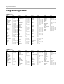
Programming the remote . . . . . . . . . . . . . . . . . . . .39~41
Troubleshooting Checklist . . . . . . . . . . . . . . . . . . . . . .42
Specifications . . . . . . . . . . . . . . . . . . . . . . . . . . . . . . . .43
After reading this manual, keep it handy for future reference.
Owner’s Manual 5
ENGLISH
Safety Instructions . . . . . . . . . . . . . . . . . . . . . . . . . . . . .2~4
Introduction
Introduction
What is a Plasma Display Panel (PDP)?
If voltage is applied to gas within glass panels, ultraviolet rays are produced and fused with a fluorescent substance. At that
instant, light is emitted. A Plasma Display is a next generation flat Display using this phenomenon.
160° - Wide angle range of vision
Your flat panel plasma screen offers an exceptionally broad viewing angle -- over 160 degrees. This means that the display is
clear and visible to viewers anywhere in the room.
Wide Screen
The screen of the Plasma Display is 71" so wide that your viewing experience is as if you are in a theater.
Multimedia
Connect your plasma display to a PC and you can use it for conferencing, games, and internet browsing. The Picture-in-Picture
feature allows you to view your PC and video images simultaneously.
Versatile
The light weight and thin size makes it easy to install your plasma display in a variety of locations where conventional TVs would
not fit.
The PDP Manufacturing Process: Why minute colored dots may be present on the PDP screen
The PDP (Plasma Display Panel) which is the display device of this product is composed of 0.9 to 2.2 million cells. A few cell
defects will normally occur in the PDP manufacturing process. Several minute colored dots visible on the screen should be acceptable. This also occurs in other PDP manufacturers' products and the tiny dots appearing does not mean that this PDP is defective.
Thus a few cell defects are not sufficient cause for the PDP to be exchanged or returned. Our production technology is designed
to minimize cell defects during the manufacture and operation of this product.
Cooling Fan Noise
In the same way that a fan is used in a PC computer to keep the CPU (Central Processing Unit) cool, the PDP is equipped with
cooling fans to cool the Monitor and improve its reliability. Therefore, a certain level of noise could occur while the fans are operating and cooling the PDP.
The fan noise doesn't have any negative effect on the PDP's efficiency or reliability. The noise from these fans is normal during the
operation of this product. We hope you understand that a certain level of noise from the cooling fans is acceptable and is not sufficient cause for the PDP to be exchanged or returned.
WARNING
TO REDUCE THE RISK OF FIRE AND ELECTRIC SHOCK, DO NOT EXPOSE THIS PRODUCT TO
RAIN OR MOISTURE.
6 Plasma Monitor
Introduction
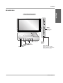
Controls
ENGLISH
Front Panel Controls
INDEX
Switches
LED Display
on or off.
INPUT
VOL
MENU
Sub power Button
E, D
Buttons
VOLUME (F,G) Buttons
MENU Button
INPUT Button
Remote
Control
Sensor
Power Indicator
Illuminates red in standby
mode, Illuminates green when
the monitor is turned on.
Owner’s Manual 7
Introduction
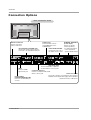
Connection Options
Back Connection Panel
S-Video Input
Connect S-Video out from
an S-VIDEO device to the
S-VIDEO input.
EXTERNAL SPEAKER
(8 ohm output)
Connect to optional
external speaker(s).
EURO SCART SOCKET * For further information,
refer to ‘Speaker &
Connect the euro scart of
Speaker Stand’ manual.
the VCR to these sockets.
Remote Control Port
Connect your wired
remote control here.
DVI Input/Audio Input/RGB Input
Connect the monitor output connector
from a PC to the appropriate input port.
VIDEO
INPUT 2
COMPONENT
INPUT 2
REMOTE
CONTROL
RS-232C INPUT
HDMI
(CONTROL/SERVICE)
DVI INPUT
AUDIO INPUT
COMPONENT
INPUT 1
RGB INPUT
VIDEO
INPUT 1
R
VIDEO
HDMI
Connect a HDMI
signal to this jack.
RS-232C INPUT
(CONTROL/SERVICE) PORT
Connect to the RS-232C port
on a PC.
8 Plasma Monitor
L
AUDIO
S-VIDEO
R
MONO
( )R( )
VIDEO3
AUDIO
( )L ( )
VIDEO4
EXTERNAL SPEAKER
L
AC INPUT
VIDEO
Audio/Video Input
Connect audio/video output from
an external device to these jacks.
Component Input (1,2)
Connect a component video/audio
device to these jacks.
Power Cord Socket
This monitor operates on an AC power. The voltage is
indicated on the Specifications page. Never attempt to
operate the monitor on DC power.
Introduction
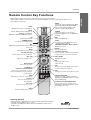
Remote Control Key Functions
MODE
Selects the remote operating mode: MNT,
VCR, DVD, CABLE, HDSTB or AUDIO.
Select other operating modes, for the
remote to operate external devices.
LIGHT
Illuminates the remote control buttons.
INPUT
Selects: Video1-2-3-4, Component 1-2,
RGB-DTV (or RGB-PC),
DVI-DTV (or DVI-PC), HDMI input sources.
PIP
Selects the PIP mode.
LIGHT
MODE
POWER
INPUT
PIP
DW
NUMBER buttons
Dosen’t work for monitor mode.
APC
Adjusts the factory preset picture according
to the room.
DASP
APC
MUTE
SLEEP
MUTE
Switches the sound on or off.
VOLUME UP/DOWN
Increases/decreases the sound level.
VOL
CH
WIN. POSITION SPLIT ZOOM
WIN. SIZE
ENTER
THUMBSTICK
(Up/Down/Left/Right/ENTER)
Allows you to navigate the on-screen
menus and adjust the system settings to
your preference.
MENU
Brings up the main menu to the screen.
DW
Selects the DW mode.
DASP
To select the sound appropriate to your
viewing program character:
SRS TSXT, Flat, Music, Movie, Sports, or
User (Refer to p.21)
SLEEP
Sets the Sleep Timer.
CHANNEL UP/DOWN
Selects available channels found with Auto
program. Dosen’t work for monitor mode.
SPLIT ZOOM
Enlarges the picture.
WIN. SIZE
Adjusts the sub picture size.
WIN.POSITION
Moves the sub picture.
POWER
Turns your monitor or any other programmed equipment on or off, depending
on mode.
XD
Switches the XD on or off.
(Refer to p.19)
EXIT
MENU
PIP INPUT
ARC
PLAY
PAUSE
STOP RECORD
REW
FF
SKIP
VIDEO
COM1
DVI
HDMI
COM2
KEY LOCK
EXIT
Clears all on-screen displays and returns to
monitor viewing from any menu.
ARC
Changes the picture format. (Refer to p.25)
RGB
INDEX
PIP INPUT
Selects the input source for
the sub picture.
KEY LOCK
Switches the key lock on or off.
VCR/DVD BUTTONS
Control some video cassette recorders or
DVD player ("RECORD" button is not available for DVD player).
VIDEO/COM1/COM2/RGB/DVI/HDMI
Selects: Video1-2-3-4, Component 1-2,
RGB-DTV (or RGB-PC), DVI-DTV (or DVIPC), HDMI input sources.
INDEX
Switches LED Display on or off.
Installing Batteries
• Open the battery compartment cover on the back side and install the batteries
matching correct polarity (+ with +, - with -).
• Install two 1.5V AA batteries. Don’t mix old or used batteries with new ones.
Replace cover.
Owner’s Manual 9
ENGLISH
- When using the remote control, aim it at the remote control sensor on the monitor.
- Under certain conditions such as if the remote IR signal is interrupted, the remote control may not function. Press
the key again as necessary.
Installation
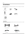
Installation
Ensure that the following accessories are included with your plasma display. If an accessory is missing, please contact the dealer
where you purchased the product.
1.5V
1.5V
Owner’s Manual
MODE
LIGHT
Power Cord
POWER
PIP
INPUT
Batteries
DW
DASP
APC
MUTE
SLEEP
VOL
CH
WIN. POSITION SPLIT ZOOM
WIN. SIZE
ENTER
EXIT
MENU
PIP INPUT
PLAY
REW
PAUSE
ARC
STOP RECORD
FF
VIDEO
COM1
DVI
HDMI
SKIP
COM2
KEY LOCK
RGB
INDEX
Remote Control
D-sub 15 pin cable
DVI computer cable
Soft cloth
(MW-71PY10G only )
Option Extras
-
Optional extras can be changed or modified for quality improvement without any notification new optional extras can be added.
Contract your dealer for buying these items.
Tilt wall mounting bracket
Video cables
10 Plasma Monitor
Desktop stand
Audio cables
Installation
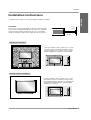
Installation Instructions
ENGLISH
• Install this monitor only in a location where adequate ventilation is available.
GROUNDING
Power
Supply
Ensure that you connect the grounding / earth wire to prevent possible
electric shock. If grounding methods are not possible, have a qualified
electrician install a separate circuit breaker. Do not try to ground the
unit by connecting it to telephone wires, lightening rods, or gas pipes.
Short-circuit
Breaker
Wall Mount Installation
For proper ventilation, allow a clearance of 4” on each
side and 2” from the wall. Detailed installation instructions are available from your dealer, see the optional
Wall Mounting Bracket Installation and Setup Guide.
2 inches
4 inches
4 inches
4 inches
4 inches
Desktop Pedestal Installation
For proper ventilation, allow a clearance of 4” on each
side and the top, 2.36” on the bottom, and 2” from the
wall. Detailed installation instructions are included in the
optional Desktop Stand Installation and Setup Guide
available from your dealer.
Owner’s Manual 11
Installation
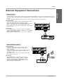
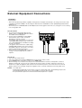
External Equipment Connections
NOTE: Not all cables shown are included with the plasma display.
VCR Setup
- To avoid picture noise (interference), leave an adequate distance between the VCR and Monitor.
- Use the ISM Method feature to avoid having a fixed image remain on the screen for a long period of time. Typically a frozen still
picture from a VCR. If the 4:3 picture format is used; the fixed image may remain visible on the screen.
How to connect
1. Connect the audio and video cables from the VCR's output
jacks to the monitor input jacks, as shown in the figure.
When connecting the monitor to VCR, match the jack colors
(Video = yellow, Audio Left = white, and Audio Right = red).
2. If you connect an S-VIDEO output from VCR to the SVIDEO input, the picture quality is improved; compared to
connecting a regular VCR to the Video input.
3. If you connect the Euro scart socket of the VCR to the Euro
scart socket of the set. No other connection is needed.
VIDEO
INPUT 2
COMPONENT
INPUT 2
COMPONENT
INPUT 1
VIDEO
INPUT 1
R
L
S-VIDEO
AUDIO
VIDEO
R
MONO
AUDIO
Mono VCR: Connect the video output cable from the VCR
to the VIDEO input on the monitor.
S-VIDEO VCR: Connect the S-Video output cable from the
VCR to the S-VIDEO input on the monitor. (Note that SVideo offers higher quality).
How to use
1. Insert a video tape into the VCR and press PLAY on the
VCR.
(Refer to the VCR owner’s manual.)
2. Use the INPUT button on the remote control to select
Video 1 or Video 3.
12 Plasma Monitor
VIDEO3
L
VIDEO
or
ANT OUT
ANT IN
S-VIDEO
OUT
OUTPUT
SWITCH
3
4
IN
(R) AUDIO (L)
VIDEO
VCR
VIDEO4
Installation
External Equipment Connections
- After subscribing to a cable monitor service from a local provider and installing a converter, you can watch cable TV programming. The monitor cannot display monitor programming unless a TV tuner device or cable TV converter box is connected to the
Monitor.
- For further information regarding cable monitor service, contact your local cable TV service provider(s).
How to connect
1. Connect the audio and video cables from the Cable Box's output
jacks to the monitor input jacks, as shown in the figure.
When connecting the monitor to a Cable Box, match the jack colors
(Video = yellow, Audio Left = white, and Audio Right = red).
Or, connect the Euro scart socket of the Cable box to the Euro scart
socket of the set.
VIDEO
INPUT 2
COMPONENT
INPUT 2
COMPONENT
INPUT 1
How to use
VIDEO
INPUT 1
R
L
S-VIDEO
AUDIO
VIDEO
R
MONO
VID
L
AUDIO
VIDEO
1. Use the INPUT button on the remote control to select Video 1.
(If connected to VIDEO 2, VIDEO 3 or VIDEO 4, select the Video 2,
Video 3 or Video 4 input source.)
2. Select your desired channel with the remote control for cable box.
(R) AUDIO (L)
VIDEO
TV
VCR
RF
Cable
Cable Box
External A/V Source Setup
How to connect
1. Connect the audio and video cables from the external
equipment's output jacks to the monitor input jacks, as
shown in the figure.
When connecting the monitor to external equipment, match
the jack colors (Video = yellow, Audio Left = white, and
Audio Right = red).
Or, connect the Euro scart socket of the External A/V to the
Euro scart socket of the set.
VIDEO
INPUT 2
COMPONENT
INPUT 2
COMPONENT
INPUT 1
VIDEO
INPUT 1
R
VIDEO
L
AUDIO
S-VIDEO
R
MONO
VID
L
AUDIO
VIDEO
Camcorder
How to use
1. Use the INPUT button on the remote control to select
Video1.(If connected to VIDEO 2, VIDEO 3 or VIDEO 4,
select the Video 2, Video 3 or Video 4 input source.)
2. Operate the corresponding external equipment. Refer to
external equipment operating guide.
Video Game Set
R
AUDIO
L
VIDEO
Owner’s Manual 13
ENGLISH
Cable TV Setup
Installation
DVD Setup
How to connect
VIDEO
INPUT 2
COMPONENT
INPUT 2
PUT
VICE)
HDMI
DVI INPUT
AUDIO INPUT
COMPONENT
INPUT 1
RGB INPUT
1. Connect the DVD video outputs to the COMPONENT (Y, PB, PR) or HDMI INPUT jacks
and connect the DVD audio outputs to the
AUDIO INPUT jacks on the monitor, as shown
in the figure.
2. If your DVD only has an S-Video output jack,
connect this to the S-VIDEO input on the monitor and connect the DVD audio outputs to the
AUDIO INPUT jacks on the monitor, as shown
in the figure.
VIDEO
INPUT 1
R
L
S-VIDEO
AUDIO
VIDEO
R
MONO
AUDIO
VID
L
VIDEO
How to use
1. Turn on the DVD player, insert a DVD.
2. Use the INPUT button on the remote control to
select Component 1, Component 2 or HDMI.
(If connected to S-VIDEO, select the Video 1
external input source.)
3. Refer to the DVD player's manual for operating instructions.
or
HDMI OUTPUT
(R) AUDIO (L)
B
(R) AUDIO (L)
R
S-VIDEO
DVD
• Component Input ports
To get better picture quality, connect a DVD
player to the component input ports as shown.
Component ports of the
Monitor
Video output ports
of DVD player
PR
Y
PB
Y
Y
Y
Y
Pr
Pb
B-Y R-Y
Cr
Cb
PB PR
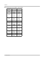
DTV Setup
- To watch digitally broadcast programs, purchase
and connect a digital set-top box.
- This monitor supports HDCP (High-bandwidth
Digital Contents Protection) protocol for DVI DTV
(480p,720p,1080i) mode.
VIDEO
INPUT 2
COMPONENT
INPUT 2
How to connect
NPUT
RVICE)
HDMI
DVI INPUT
AUDIO INPUT
COMPONENT
INPUT 1
RGB INPUT
VIDEO
INPUT 1
R
1. Use the monitor’s COMPONENT (Y, PB, PR)
INPUT, RGB, DVI or HDMI jack for video connections, depending on your set-top box connector.
Then, make the corresponding audio connections.
L
AUDIO
VIDEO
S-VIDEO
R
MONO
L
AUDIO
VIDEO
How to use
1. Turn on the digital set-top box. (Refer to the
owner’s manual for the digital set-top box.)
2. Use INPUT on the remote control to select
Component 1, Component 2, RGB, DVI or
HDMI.
DVI-DTV OUTPUT
(R) AUDIO (L)
RGB-DTV
DVI-DTV
O
O
X
X
X
480p
O
O
O
O
O
720p
O
O
O
O
O
1080i
O
O
O
O
O
1080p
X
X
O
X
X
14 Plasma Monitor
RGB-DTV OUTPUT
Digital Set-top Box
480i
Signal
Component1 Component2
or
HDMI OUTPUT
HDMI
(R) AUDIO (L)
B
R
VID
Installation
External Equipment Connections
- This monitor provides Plug and Play capability, meaning that the PC adjusts automatically to its settings. The monitor sends
configuration information (EDID) to the PC using the Video Electronics Standard Association (VESA) Display Data Channel
(DDC) protocol.
- The monitor perceives 640x480, 60Hz as DTV 480p based on the PC graphic card. In this case, change the screen scanning
rate for the graphic card.
How to connect
1. To get the best picture quality, adjust the PC
graphics card to a 1280x1024, 60Hz. Resolutions
over UXGA cannot be displayed.
2. Use the monitor’s RGB INPUT or DVI (Digital
Visual Interface) port for video connections,
depending on your PC connector.
If the graphic card on the PC does not output analog and digital RGB simultaneously, connect only
one of either RGB INPUT or DVI INPUT to display
the PC on the monitor.
If the graphic card on the PC does output analog
and digital RGB simultaneously, set the monitor to
either RGB or DVI; (the other mode is set to Plug
and Play automatically by the monitor.)
3. Then, make the corresponding audio connections.
If using a sound card, adjust the PC sound as
required.
COMPONEN
INPUT 2
C INPUT
SERVICE)
HDMI
DVI INPUT
AUDIO INPUT
COMPONEN
INPUT 1
RGB INPUT
VIDEO
How to use
1. Turn on the PC and the monitor.
2. Turn on the display by pressing the POWER button on the monitor's remote control.
3. Use the INPUT button on the remote control to select RGB or DVI.
4. Check the image on your monitor. There may be noise associated with the resolution, vertical pattern, contrast or
brightness in PC mode. If noise is present, change the PC mode to another resolution, change the refresh rate to
another rate or adjust the brightness and contrast on the menu until the picture is clear. If the refresh rate of the PC
graphic card can not be changed, change the PC graphic card or consult the manufacturer of the PC graphic card.
NOTES: • Use a DVI cable.
• Avoid keeping a fixed image on the monitor's screen for a long period of time. The fixed image may become
permanently imprinted on the screen. Use the Orbiter screen saver when possible.
• The synchronization input form for Horizontal and Vertical frequencies is separate.
Owner’s Manual 15
ENGLISH
PC Setup
Installation
Monitor Display Specifications (RGB-PC / DVI-PC Mode)
Resolution
720x400
640x480
800x600
832x624
848x480
852x480
1024x768
1152x864
1280x960
1280x1024
16 Plasma Monitor
Horizontal
Vertical
Frequency(KHz) Frequency(Hz)
31.469
70.08
37.927
85.03
31.469
59.94
35.000
66.66
37.861
72.80
37.500
75.00
43.269
85.00
35.156
56.25
37.879
60.31
46.875
75.00
53.674
85.06
49.725
74.55
31.500
60.00
35.000
70.00
37.500
75.00
31.500
60.00
35.000
70.00
37.500
75.00
48.363
60.00
56.476
70.06
60.023
75.02
54.348
60.05
63.995
70.01
67.500
75.00
60.000
60.00
63.981
60.02
80.000
75.00
Installation
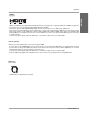
HDMI
How to connect
When Source Devices(DVD Player or Set Top Box) support HDMI.
- If Source Devices have HDMI Output Connector, Source Devices connect to DTV with HDMI Cable .(not supplied with the product).
- If Source Devices support Auto HDMI, automatically, Source Devices divert output resolution in 1920 x 1080i. But if not, resolution
divert Manually Setting for reference Manual of Source Devices.
- To get the best picture quality, adjust the DVD Player or Set Top Box output resolution to 1920 x 1080i.
- Because HDMI sends Digital Video and Audio with one cable, need not especial Audio Cable for using HDMI Cable.
Reference
Cable sample
HDMI Cable (not supplied with the product)
Owner’s Manual 17
ENGLISH
- HDMITM, the HDMI logo and High-Definition Multimedia Interface are trademarks or registered trademarks of HDMI Licensing LLC."
- This monitor can receive the High-Definition Multimedia Interface(HDMI).
- This monitor supports HDCP(High-bandwidth Digital Contents Protection) Protocol for 480p, 720p, 1080i modes.
- When you Connect with HDMI Source Devices (DVD Player or Set Top Box) supporting Auto HDMI function, automatically, support
Plug & Play and then set the HDMI Source Devices(1920 x 1080i). After reading in HDMI Source Devices using Display Data
Channel(DDC) Protocol, EDID stored in monitor is used. If HDMI Source Devices not supported Auto HDMI is been, the Resolution
is setted, manually.
- To get the best picture quality, adjust the DVD Player or Set Top Box output resolution to 1920 x 1080i.
Operation
Operation
Turning on the Monitor
Turning on the Monitor just after installation
1. Connect power cord correctly. At this moment, the Monitor is switched to standby mode.
2. Press the INPUT or
button on the Monitor or press the POWER, INPUT button on the remote
control and then the Monitor will switch on.
Menu Language Selection
- The menus can be shown on the screen in the selected language. First select your language.
1. Press the MENU button and then use
2. Press the G button and then use D /
E
D
/
E
button to select the SPECIAL menu.
button to select Language.
3. Press the G button and then use D / E button to select your desired language.
From this point on, the on-screen menus will be shown in the language of your choice.
4. Press the ENTER button to save.
• Press the MENU button to return to the previous menu.
18 Plasma Monitor
Operation
Picture Menu Options
ENGLISH
- Readjust Picture menu settings for each following input source as preferred.
APC (Auto Picture Control)
- APC adjusts the Monitor for the best picture appearance.
- When adjusting Picture menu options (contrast, brightness, color, sharpness, and tint) manually, APC automatically changes to Off.
1. Press the APC button repeatedly to select the picture appearance setup option as shown below.
Daylight
Optimum
Night time
Off
• You can also select Daylight, Optimum, Night time or Off in the PICTURE menu.
• Daylight, Optimum, and Night time settings are preset for optimum picture quality at the factory and cannot be
changed.
XD
- XD is LG Electronic’s unique picture improving technology to display a real HD
source through an advanced digital signal processing algorithm.
- When selecting APC options (Daylight, Optimum and Night time), XD is automatically change to On.
1. Press the
button repeatedly as shown below.
On
Off
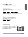
Auto Color Temperature Control
- To initialize values (reset to default settings), select the Normal option.
1. Press the MENU button and then use D
2. Press the
G
button and then use
D /E
3. Press the G button and then use D
Normal (Default), Warm (Preset).
/E
button to select the PICTURE menu.
button to select ACC .
PICTURE
SOUND
/E
button to select either Cool (Preset),
4. Press the ENTER button to save the new settings.
TIMER
SPECIAL
SCREEN
PIP/DW
APC
ACC
Fleshtone
Contrast
Brightness
Color
Sharpness
Tint
Menu
G
Cool
Normal
Warm
100
55
55
60
0
Prev.
Owner’s Manual 19
Operation
Picture Menu Options continued
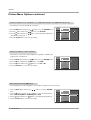
Fleshtone (Video1-2-3-4,
(Video1-2-3-4, Component 1-2, RGB-DTV,
RGB-DTV, DVI-DTV and HDMI-DTV Mode only)
- Use Fleshtone to select the desired skin color option.
PICTURE
1. Press the MENU button and then use D
/E
button to select the PICTURE menu.
2. Press the G button and then use
D /E
button to select Fleshtone.
3. Press the G button and then use
F / G button
to make appropriate adjustments.
• The adjustment range is 0 ~ 3.
SOUND
TIMER
SPECIAL
SCREEN
4. Press the ENTER button to save the new settings.
PIP/DW
APC
ACC
Fleshtone
Contrast
Brightness
Color
Sharpness
Tint
Menu
G
0
100
55
55
60
0
Prev.
sRGB (only RGB-PC, DVI-PC Modes)
- If the monitor is connected to external equipment using sRGB, set sRGB to On
to adjust for the color difference.
PICTURE
1. Press the MENU button and then use D
/E
2. Press the G button and then use
D /E
button to select sRGB.
D /E
button to select On or Off.
3. Press the
G
button and then use
button to select the PICTURE menu.
4. Press the ENTER button to save the new settings.
SOUND
TIMER
SPECIAL
APC
ACC
sRGB
Contrast
Brightness
Color
G
On
Off
100
55
55
SCREEN
PIP/DW
Menu
Prev.
Manual Picture Control ( Off option)
- You can adjust picture contrast, brightness, color, sharpness, and tint to the levels you prefer.
1. Press the MENU button and then use
menu.
D / E
button to select the PICTURE
2. Press the G button and then use D / E button to select the desired picture
option (Contrast, Brightness, Color, Sharpness or Tint).
3. Press the G button and then use F
/ G button
to make appropriate adjustments.
4. Press the ENTER button to save the new settings.
PICTURE
SOUND
TIMER
SPECIAL
SCREEN
PIP/DW
20 Plasma Monitor
APC
ACC
Fleshtone
Contrast
Brightness
Color
Sharpness
Tint
Menu
Prev.
100
60
50
50
0
G
Operation
Sound Menu Options
ENGLISH
DASP (Digital Auto Sound Processing)
- DASP lets you enjoy the best sound without any special adjustment because the Monitor has the appropriate
sound options based on the program content.
- When adjusting sound options (treble, bass) manually, DASP automatically changes to Off.
1. Press the DASP button repeatedly to select the appropriate sound setup as shown below.
SRS TSXT
Flat
Music
Movie
Off
Sports
• You can also adjust DASP in the SOUND menu.
• SRS TSXT, Flat, Music, Movie, and Sports are preset for good sound quality at the factory and cannot be changed.
•
is a trademark of SRS Labs, Inc.
• TruSurround XT technology is incorporated under license from SRS Labs, Inc.
Manual Sound Control (Dasp Off option and balance)
PICTURE
1. Press the MENU button and then use D
2. Press the G button and then use
(Balance, Treble or Bass).
3. Press the
G
button and then use
/E
button to select the SOUND menu.
D /E
button to select the desired sound option
F /G
button to make appropriate adjustments.
SOUND
TIMER
DASP
BBE
AVL
Balance
Treble
Bass
0
50
50
G
L
R
SPECIAL
SCREEN
4. Press the ENTER button to save the new settings.
PIP/DW
Menu
Prev.
BBE
- BBE High Definition Sound restores clarity and presence for better speech intelligibility and musical realism.
1. Press the MENU button and then use D
2. Press the G button and then use
3. Press the
G
button and then use
/E
button to select the SOUND menu.
PICTURE
D /E
button to select BBE.
SOUND
D /E
button to select On or Off.
TIMER
4. Press the ENTER button to save the new settings.
DASP
BBE
AVL
Balance
Treble
Bass
G
On
Off
G
On
Off
0
50
50
SPECIAL
SCREEN
•
Manufactured under license from BBE Sound, Inc.
PIP/DW
• Treble, Bass or BBE aren’t suitable for SRS TSXT mode.
Menu
Prev.
AVL (Auto Volume
Volume Leveler)
- This feature maintains an equal volume level; even if you change channels.
1. Press the MENU button and then use
D /E
button to select the SOUND menu.
2. Press the
G
button and then use
D /E
button to select AVL.
3. Press the
G
button and then use
D /E
button to select On or Off.
4. Press the ENTER button to save the new settings.
PICTURE
SOUND
TIMER
DASP
BBE
AVL
Balance
Treble
Bass
0
50
50
SPECIAL
SCREEN
PIP/DW
Menu
Prev.
Owner’s Manual 21
Operation
T imer Menu Options
Clock Setup
- If current time setting is wrong, correct the clock setting.
1. Press the MENU button and then use
D /E
button to select the TIMER menu.
2. Press the
G
button and then use
D /E
button to select Clock.
3. Press the
G
button and then use
D /E
button to set the hour.
4. Press the
G
button and then use
D /E
button to set the minutes.
PICTURE
SOUND
Clock
Off timer
On timer
Auto off
G
-- :
--
AM
TIMER
SPECIAL
5. Press the ENTER button to save the new settings.
SCREEN
PIP/DW
Menu
Prev.
On/Off
On/Off Timer Setup
- Timer function operates only if current time has already been set.
- Off-Timer function overrides On-Timer function if they are set to the same time.
- If you do not press any button within 2 hours after the monitor turns on with the On Timer function, the monitor will
automatically revert to standby mode.
1. Press the MENU button and then use
2. Press the
G
button and then use
D /E
D /E
button to select the TIMER menu.
button to select Off timer or On timer.
PICTURE
3. Press the G button and then use D / E button to select On.
• To cancel On/Off timer function, select Off.
SOUND
G
button and then use
D /E
button to set the hour.
5. Press the
G
button and then use
D /E
button to set the minutes.
G
G
On
Off
6 : 30 AM
Volume
17
G
On
Off
TIMER
4. Press the
For only On timer function; Press the
set volume level.
Clock
Off timer
On timer
Auto off
SPECIAL
SCREEN
button and then use
D /E
button to
PIP/DW
Menu
Prev.
6. Press the ENTER button to save the new settings.
Auto Off
Off
- If there is no input signal, the Monitor turns off automatically after 10 minutes.
PICTURE
1. Press the MENU button and then use
D /E
button to select the TIMER menu.
2. Press the G button and then use
D /E
button to select Auto off.
3. Press the G button and then use
D /E
button to select On or Off.
SOUND
Clock
Off timer
On timer
Auto off
TIMER
SPECIAL
4. Press the ENTER button to save the new settings.
SCREEN
PIP/DW
Menu
Prev.
Sleep Timer
- The sleep timer turns the Monitor off at a preset time. Note that this setting is cleared when the monitor is turned off.
zz
1. Press the SLEEP button repeatedly to select the number of minutes. First the
--- Min option appears on the
screen, followed by the following sleep timer options: 10, 20, 30, 60, 90, 120, 180, and 240 minutes.
2. When the number of minutes you want is displayed on the screen, press the ENTER button. The timer begins to
count down from the number of minutes selected.
3. To check the remaining minutes before the monitor turns off, press the SLEEP or ENTER button once.
4. To cancel the Sleep Timer, press the SLEEP button repeatedly until
22 Plasma Monitor
zz
--- Min appears.
Operation
Special Menu Options
ENGLISH
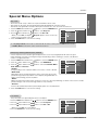
Key Lock
- The monitor can be set up so that it can only be used with the remote control.
- This feature can be used to prevent unauthorized viewing by disabling the front panel controls.
- This Monitor is programmed to remember which option it was last set to even if you turn the monitor off.
1. Press the MENU button and then use D
2. Press the
G
button and then use
D /E
button to select the SPECIAL menu.
/E
PICTURE
button to select Key lock.
SOUND
3. Press the G button and then use
D /E
button to select On or Off.
TIMER
• When you select On, the display ‘ W
Key lock’ appears on the screen if any
button on the front panel is pressed.
4. Press the ENTER button to save the new settings.
SPECIAL
Language
Key lock
ISM Method
Low power
Set ID
Demo
Index
G
On
Off
SCREEN
PIP/DW
Menu
Prev.
-In setting Key lock ‘On’, if the monitor is turned off with the remote control, press the INPUT on the monitor
or POWER, INPUT on the remote control to turn the monitor on.
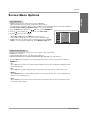
ISM (Image Sticking Minimization) Method
- A frozen still picture from a PC/video game displayed on the screen for prolonged periods will result in an ghost
image remaining; even when you change the image. Avoid allowing a fixed or still image to remain on the Monitor's
screen for a long period of time.
1. Press the MENU button and then use D
2. Press the
G
button to select the SPECIAL menu.
/E
button and then use
D /E
button to select ISM Method.
3. Press the G button and then use
wash, Orbiter, or Inversion.
D /E
button to select either Normal, White
PICTURE
SOUND
TIMER
SPECIAL
• Normal
If image sticking is never a problem, ISM is not necessary - set this to Normal.
Language
Key lock
ISM Method
Low power
Set ID
Demo
Index
G
Normal
White wash
Orbiter
Inversion
SCREEN
PIP/DW
• White wash
White Wash removes permanent images from the screen. Note: An excessive
permanent image may be impossible to clear completely using White Wash. To
return to normal viewing, press the any button.
Menu
Prev.
• Orbiter
Orbiter may help prevent ghost images. However, it is best not to allow any fixed image to remain on the screen. To avoid a
permanent image on the screen, the image will move every 2 minutes.
• Inversion
Inversion will automatically invert the plasma display panel color every 30 minutes.
4. Press the ENTER button to save the new settings.
Low Power
- Low power reduces the plasma display's power consumption.
1. Press the MENU button and then use D
/E
button to select the SPECIAL menu.
2. Press the
G
button and then use
D /E
button to select Low power.
3. Press the
G
button and then use
D /E
button to select On or Off.
PICTURE
SOUND
TIMER
SPECIAL
Language
Key lock
ISM Method
Low power
Set ID
Demo
Index
G
On
Off
• When you select On, the screen darkens.
4. Press the ENTER button to save the new settings.
SCREEN
PIP/DW
Menu
Prev.
Owner’s Manual 23
Operation
Special Menu Options continued
XD Demo
- Use it to see the difference between XD Demo on and XD Demo off.
1. Press the MENU button and then use D
/E
2. Press the
G
button and then use
3. Press the
G
button to begin XD Demo.
D
button to select the SPECIAL menu.
/ E button to select
Demo.
PICTURE
SOUND
TIMER
SPECIAL
4. Press the EXIT button to stop XD Demo.
Language
Key lock
ISM Method
Low power
Set ID
Demo
Index
G
To start
G
On
Off
SCREEN
PIP/DW
Menu
Prev.
INDEX
- Switches LED Display on or off.
PICTURE
1. Press the MENU button and then use D
2. Press the
G
button and then use
3. Press the G button and then use
D /E
D /E
/E
button to select the SPECIAL menu.
button to select Index.
button to select On or Off.
4. Press the ENTER button to save the new settings.
SOUND
TIMER
SPECIAL
SCREEN
PIP/DW
24 Plasma Monitor
Language
Key lock
ISM Method
Low power
Set ID
Demo
Index
Menu
Prev.
Operation
Screen Menu Options
-
RGB (PC) mode only; This function doesn’t work for RGB-DTV.
Automatically adjusts picture position and minimizes image shaking.
After adjustment, if the image is still not correct, your Monitor is functioning properly but needs further adjustment.
The Auto config., Position and Manual config. are not active in DVI mode.
1. Press the MENU button and then use
2. Press the
G
button and then use
D /E
D /E
button to select the SCREEN menu.
button to select Auto config..
3. Press the G button to run Auto configure.
• When Auto config. has finished, OK will be shown on screen.
• If the position of the image is still not correct, try Auto adjustment again.
4. In RGB (PC) mode, if the image needs to be adjusted more after using Auto
config., you can make further adjustments with the Manual config. option.
PICTURE
SOUND
TIMER
Auto config.
ARC
Position
Manual config.
Reset
VGA Mode
G
To start
SPECIAL
SCREEN
PIP/DW
Menu
Prev.
Setting Picture Format
-
Caution: If a 4:3 fixed image is on the screen for a long time, it may remain visible.
RGB/DVI-PC: 4:3, 16:9
Component 480i, Video sources : 4:3, 16:9, Horizon and Zoom.
RGB-DTV/DVI-DTV/Component 480p,720p,1080i/HDMI 480p,720p,1080i : 4:3, 16:9 and Zoom.
1. Press the ARC button repeatedly to select the desired picture format. You can also select picture format in the
SCREEN menu.
• 4:3
- Choose 4:3 when you want to view a picture with an original 4:3 aspect ratio, with black bars appearing at both
the left and right sides.
• 16:9
- Choose 16:9 when you want to adjust the picture horizontally, in a linear proportion to fill the entire screen.
• Horizon
- Choose Horizon when you want to adjust the picture in a non-linear proportion, that is, more enlarged at both
sides, to create a spectacular view.
• Zoom
- Choose Zoom when you want to view the picture without any alteration. However, the top and bottom portions
of the picture will be cropped.
Owner’s Manual 25
ENGLISH
Auto Adjustment
Operation
Split Zoom
-
Enlarges the picture in correct proportions.
Split Zoom can be used for all input sources.
In 2-Split Zoom mode, you can only move the image up or down.
If a screen is enlarged, a screen can move without selecting section of screen Split Zoom.
1. Press the SPLIT ZOOM button repeatedly to select either 2, 4 , or 9 Split Zoom.
9-Split zoom
4-Split zoom
2-Split zoom
1
1
2
1
4
4
4
5
7
2
5
8
3
6
9
2. Press the number button corresponding to the section you wish to enlarge. You can move within the enlarged
image with the D / E / F / G button. To return to normal viewing, press the SPLIT ZOOM button again.
1
4
7
2
5
8
Section 5 is enlarged to fill
the screen.
Example of choosing 5.
9-Split zoom
3
6
9
Screen Position
- This function works in the following mode:
RGB-PC, RGB-DTV (480p,720p,1080i,1080p), COMPONENT (480p,720p,1080i).
1. Press the MENU button and then use
menu.
button to select the SCREEN
D /E
2. Press the
G
button and then use
D /E
3. Press the
G
button and then use
D /E /F /G
button to select Position.
button to adjust the position.
4. Press the ENTER button to save the new settings.
PICTURE
SOUND
TIMER
Auto config.
ARC
Position
Manual config.
Reset
VGA Mode
G
D
F
G
E
SPECIAL
SCREEN
PIP/DW
Menu
Prev.
Manual Configure (RGB-PC mode only)
- If the image still isn’t clear after auto adjustment is completed and especially if characters are still jittery, adjust the
picture Phase manually.
- To correct the screen size, adjust Clock.
1. Press the MENU button and then use
menu.
D /E
2. Press the G button and then use
D /E
button to select Manual config..
3. Press the G button and then use
D /E
button to to select Phase or Clock.
4. Use the
F /G
button to select the SCREEN
button to make appropriate adjustments.
• The Phase adjustment range is 0 ~ 30.
• The Clock adjustment range is -127 ~ +128.
5. Press the ENTER button to save the new settings.
26 Plasma Monitor
PICTURE
SOUND
TIMER
Auto config.
ARC
Position
Manual config.
Reset
VGA Mode
SPECIAL
SCREEN
PIP/DW
Menu
Prev.
G
Phase
0
Clock
0
Operation
Screen Menu Options continued
ENGLISH
Initializing (Reset to original factory value)
- This function operates in every mode.
- To initialize the adjusted value.
1. Press the MENU button and then use
menu.
D /E
2. Press the G button and then use
button to select Reset.
D /E
button to select the SCREEN
PICTURE
SOUND
3. Press the G button.
TIMER
Auto config.
ARC
Position
Manual config.
Reset
VGA Mode
G
To start
SPECIAL
• You can initialize Manual config., Position, Split zoom, PIP size, PIP position, PIP transparency and sub picture size for DW.
SCREEN
PIP/DW
Menu
Prev.
Selecting Wide
Wide VGA mode (RGB-PC mode only)
- To see a normal picture, match the resolution of RGB VGA mode (640x480, 848x480, 852x480) with the selection for VGA
mode in the SCREEN menu.
1. Press the MENU button and then use
menu.
2. Press the G button and then use
D /E
button to select the SCREEN
PICTURE
SOUND
D /E
3. Press the G button and then use D
olution.
button to select VGA Mode.
TIMER
/E
button to select the desired VGA res-
4. Press the ENTER button to save the new settings.
Auto config.
ARC
Position
Manual config.
Reset
VGA Mode
SPECIAL
G
640x480
848x480
852x480
SCREEN
PIP/DW
Menu
Prev.
Owner’s Manual 27
Operation
Screen Menu Options continued
Screen Adjustments (Video1-2
(Video1-2 and Component 480i mode only)
- Use this function to correct jittering or picture instability while viewing a video tape.
1. Press the MENU button and then use D
/E
button to select the SCREEN menu.
PICTURE
2. Press the G button and then use
D /E
button to select Screen adj..
3. Press the G button and then use
D /E
button to select TV or VCR.
TIMER
• Select the VCR option if watching a VCR.
• Select the TV option for other equipment. (Except VCR)
4. Press the ENTER button to save the new settings.
Screen adj.
G
ARC
SOUND
TV
VCR
Cinema
YNR
Reset
SPECIAL
SCREEN
PIP/DW
Menu
Prev.
Cinema Mode Setup (Video1-2
(Video1-2 and Component 480i mode only)
- Sets up the monitor for the best picture appearance for viewing movies.
PICTURE
1. Press the MENU button and then use D
2. Press the
G
button and then use
D /E
/E
button to select the SCREEN menu.
button to select Cinema..
Screen adj.
ARC
SOUND
TIMER
G
Cinema
YNR
On
Off
Reset
3. Press the
G
button and then use
D /E
button to select On or Off.
4. Press the ENTER button to save the new settings.
SPECIAL
SCREEN
PIP/DW
Menu
Prev.
Luminance Noise Reduction (Video
(Video 1-2 and Component 480i modes only)
- Use YNR to reduce the picture noise that may appear on the screen.
PICTURE
1. Press the MENU button and then use D
2. Press the
G
button and then use
D /E
/E
button to select the SCREEN menu.
button to select YNR.
TIMER
3. Press the G button and then use
D /E
Screen adj.
ARC
SOUND
button to select On or Off.
Cinema
G
YNR
SPECIAL
4. Press the ENTER button to save the new settings.
SCREEN
PIP/DW
28 Plasma Monitor
Menu
On
Off
Reset
Prev.
Operation
PIP (Picture-In-Picture) Feature
PIP Size
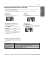
Watching PIP
Press the PIP button repeatedly to turn PIP on or off.
Press the WIN.SIZE button and then use
change the sub picture size.
F / G
button to
Component
Video
10 : 30
Win.size
F
PIP Transparency (PIP Mode only)
Moving the PIP
- To make the PIP clear or opaque.
1. Press the MENU button and then use
select the PIP/DW menu.
D /E
2. Press the G button and then use D
Transparency .
button to select PIP
/E
3. Press the G button and then use F
PIP transparency.
4. Use the
F / G button
/G
G
button to
Press the WIN.POSITION button.
Press the D / E / F / G button repeatedly until desired position is achieved. The sub picture moves up/down/left/right.
button to adjust
Win.position
to make appropriate adjustments.
• The adjustment range of PIP Transparency is 0 ~ 10.
5. Press the ENTER button to save.
Selecting an Input Signal Source for the PIP
Use the PIP INPUT button to select the input source for the
sub picture.
Main Picture Source
Video
Component 480i
Component 480p/720p/1080i
RGB/DVI-DTV(480p/720p/1080i)
RGB/DVI-PC
HDMI 480p/720p/1080i
Available Sub Picture Sources
Video, Component 480i/480p/720p/1080i, RGB/DVI/HDMI 480p/720p/1080i, RGB/DVI-PC
Video, Component 480i/480p/720p/1080i, RGB/DVI/HDMI 480p/720p/1080i, RGB/DVI-PC
Video, Component 480i, RGB/DVI 480p/720p/1080i, RGB/DVI-PC
Video and Component 480i/480p/720p/1080i
Video and Component 480i/480p/720p/1080i
Video and Component 480i
Owner’s Manual 29
ENGLISH
- PIP lets you view 2 different inputs (sources) on your monitor screen at the same time. One source will be large, and the
other source will show a smaller inset image.
- This function doesn’t work for RGB-DTV(1080p).
- If input signals(50Hz/60Hz) of the main and sub pictures are different in PIP/DW mode, the screens are unnatural.
Operation
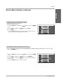
DW Setup Option
- As the name suggests, this mode splits the screen into 2, allowing 2 picture sources to be shown on the monitor screen at the
same time. Each source is given half the screen.
- This function doesn’t work for RGB-DTV(1080p).
Watching DW
Press the DW button repeatedly to select one of the DW options.
DW 1
DW 2
Sub Picture Size Adjustment
Press the WIN.SIZE button.
• Use the F / G button to change the sub picture size.
• Using the WIN.SIZE function in DW mode, main and sub picture sizes are changed
simultaneously.
Using the WIN.SIZE function in PIP mode, sub picture size is changed.
• WIN.POSITION is not functional in DW mode.
Win.size
F
G
Selecting a Source for the DW
Use the PIP INPUT button to select the input source for the sub picture.
Main Picture Source
Video
Component 480i
Component 480p/720p/1080i
RGB/DVI-DTV(480p/720p/1080i)
RGB/DVI-PC
HDMI 480p/720p/1080i
30 Plasma Monitor
Available Sub Picture Sources
Video, Component 480i/480p/720p/1080i, RGB/DVI/HDMI 480p/720p/1080i, RGB/DVI-PC
Video, Component 480i/480p/720p/1080i, RGB/DVI/HDMI 480p/720p/1080i, RGB/DVI-PC
Video, Component 480i, RGB/DVI 480p/720p/1080i, RGB/DVI-PC
Video and Component 480i/480p/720p/1080i
Video and Component 480i/480p/720p/1080i
Video and Component 480i
External Control Device Setup
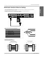
External Control Device Setup
ENGLISH
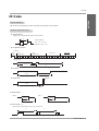
- Connect the RS-232C input jack to an external control device (such as a computer or an A/V control system)
and control the Monitor’s functions externally.
- Connect the serial port of the control device to the RS-232C jack on the Monitor back panel.
- RS-232C connection cables are not supplied with the Monitor.
VIDEO
INPUT 2
COMPONENT
INPUT 2
REMOTE
CONTROL
RS-232C INPUT
(CONTROL/SERVICE)
HDMI
DVI INPUT
AUDIO INPUT
COMPONENT
INPUT 1
RGB INPUT
VIDEO
INPUT 1
R
VIDEO
L
AUDIO
S-VIDEO
R
MONO
AUDIO
( )R( )
VIDEO3
( )L ( )
VIDEO4
EXTERNAL SPEAKER
L
AC INPUT
VIDEO
Type of Connector: D-Sub 9-pin Male
No.
1
2
3
4
5
6
7
8
9
1
Pin Name
No Connection
RXD (Receive data)
TXD (Transmit data)
DTR (DTE side ready)
GND
DSR (DCE side ready)
RTS (Ready to send)
CTS (Clear to send)
No Connection
5
9
6
RS-232C Configurations
3- Wire Configuration
(Not standard)
7-Wire Configuration
(Standard RS-232C cable)
RXD
TXD
GND
DTR
DSR
RTS
CTS
PC
PDP
2
3
5
4
6
7
8
3
2
5
6
4
8
7
D-Sub 9
D-Sub 9
TXD
RXD
GND
DSR
DTR
CTS
RTS
RXD
TXD
GND
DTR
DSR
RTS
CTS
PC
PDP
2
3
5
4
6
7
8
3
2
5
4
6
7
8
D-Sub 9
D-Sub 9
TXD
RXD
GND
DTR
DSR
RTS
CTS
Owner’s Manual 31
External Control Device Setup
Set ID
- Use this function to specify a monitor ID number.
- Refer to ‘Real Data Mapping 1’. See page 34.
1. Press the MENU button and then use the
menu.
2. Press the
G
button and then use
D /E
3. Press the G button and then use
desired monitor ID number.
F /G
D /E
button to select the SPECIAL
PICTURE
SOUND
button to select Set ID.
TIMER
button to adjust Set ID to choose the
SPECIAL
Language
Key lock
ISM Method
Low power
Set ID
Demo
Index
G
1
SCREEN
• The adjustment range of Set ID is 1 ~ 99.
PIP/DW
Menu
Prev.
Communication Parameters
• Baud rate : 9600 bps (UART)
• Data length : 8 bits
• Parity : None
• Stop bit : 1 bit
• Communication code : ASCII code
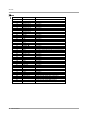
Command Reference List
Transmission / Receiving Protocol
COMMAND 1 COMMAND 2
DATA
(Hexadecimal)
01. Power
02. Input Select
03. Aspect Ratio
04. Screen Mute
05. Volume Mute
06. Volume Control
07. Contrast
08. Brightness
09. Color
10. Tint
11. Sharpness
12. OSD Select
13. Remote Control Lock Mode
14. PIP/DW
15. Split Zoom
16. PIP Position
17. Treble
18. Bass
19. Balance
20. Color Temperature
21. PIP Input Select
22. Abnormal State
23. ISM Method
24. Low Power
25. Picture Size Setting
for DW mode
26. Auto Configure
27. Key
k
k
k
k
k
k
k
k
k
k
k
k
k
k
k
k
k
k
k
k
k
k
j
j
j
a
b
c
d
e
f
g
h
i
j
k
l
m
n
p
q
r
s
t
u
y
z
p
q
t
0~1
1~9
0~3
0~1
0~1
0 ~ 64
0 ~ 64
0 ~ 64
0 ~ 64
0 ~ 64
0 ~ 64
0~1
0~1
0~3
0 ~99
0~3
0 ~ 64
0 ~ 64
0 ~ 64
0~2
1~9
0~a
0~3
0~1
0 ~30
j
m
u
c
1
Key code
Transmission
[Command1][Command2][ ][Set ID][ ][Data][Cr]
* [Command 1]: k, j, m
* [Command 2]: To control PDP set.
* [Set ID]: You can adjust the set ID to choose desired monitor ID number in Special menu. Adjustment range
is 1 ~ 99. When selecting Set ID ‘0’, every connected PDP set is controlled. Set ID is indicated
as decimal (1~99) on menu and as Hexa decimal
(0x0~0x63) on transmission/receiving protocol.
* [DATA]: To transmit command data.
Transmit ‘FF’ data to read status of command.
* [Cr]: Carriage Return
ASCII code ‘0x0D’
* [ ]: ASCII code ‘space (0x20)’
OK Acknowledgement
[Command2][ ][Set ID][ ][OK][Data][x]
* The Monitor transmits ACK (acknowledgement) based on
this format when receiving normal data. At this time, if the
data is data read mode, it indicates present status data. If
the data is data write mode, it returns the data of the PC
computer.
Error Acknowledgement
[Command2][ ][Set ID][ ][NG][x]
* The Monitor transmits ACK (acknowledgement) based on
this format when receiving abnormal data from
non-viable functions or communication errors.
Data 1: Illegal Code
2: Not supported function
32 Plasma Monitor
External Control Device Setup
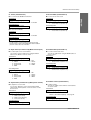
04. Screen Mute (Command 2:d)
G To control Power On/Off of the Monitor.
G To select screen mute on/off.
Transmission
Transmission
[k][a][ ][Set ID][ ][Data][Cr]
Data 0 : Power Off
ENGLISH
01. Power (Command 2:a)
[k][d][ ][Set ID][ ][Data][Cr]
1 : Power On
Acknowledgement
Data 0 : Screen mute off (Picture on)
1 : Screen mute on (Picture off)
[a][ ][Set ID][ ][OK][Data][x]
Acknowledgement
[d][ ][Set ID][ ][OK][Data][x]
G To show Power On/Off.
Data 0 : Screen mute off (Picture on)
1 : Screen mute on (Picture off)
Transmission
[k][a][ ][Set ID][ ][FF][Cr]
Data 0 : Power Off
1 : Power On
Acknowledgement
[a][ ][Set ID][ ][OK][Data][x]
* In a like manner, if other functions transmit ‘FF’ data
based on this format, Acknowledgement data feedback
presents status about each function.
02. Input Select (Command 2:b) (Main Picture Input)
05. Volume Mute (Command 2:e)
G To select input source for the Monitor.
You can also select an input source using the INPUT
button on the Monitor's remote control.
G To control volume mute on/off.
You can also adjust mute using the MUTE button on
remote control.
Transmission
Transmission
[k][e][ ][Set ID][ ][Data][Cr]
[k][b][ ][Set ID][ ][Data][Cr]
Data 1
2
3
4
5
:
:
:
:
:
Video1
Video2
Component1
Component2
RGB
6
7
8
9
:
:
:
:
DVI
Video3
Video4
HDMI
Data 0 : Volume mute on (Volume off)
1 : Volume mute off (Volume on)
Acknowledgement
[e][ ][Set ID][ ][OK][Data][x]
Data 0 : Volume mute on (Volume off)
1 : Volume mute off (Volume on)
Acknowledgement
[b][ ][Set ID][ ][OK][Data][x]
Data 1
2
3
4
5
:
:
:
:
:
Video1
Video2
Component1
Component2
RGB
6
7
8
9
:
:
:
:
DVI
Video3
Video4
HDMI
03. Aspect Ratio (Command 2:c) (Main picture format)
G To adjust the screen format.
You can also adjust the screen format using the ARC
(Aspect Ratio Control) button on remote control or in the
Screen menu.
Transmission
[k][c][ ][Set ID][ ][Data][Cr]
Data 0
1
2
3
:
:
:
:
Normal screen (4:3)
Wide screen (16:9)
Wide screen (Horizon)
Full screen (Zoom)
Acknowledgement
06. Volume Control (Command 2:f)
G To adjust volume.
You can also adjust volume with the volume buttons
on remote control.
Transmission
[k][f][ ][Set ID][ ][Data][Cr]
Data Min : 0 ~ Max : 64
• Refer to ‘Real data mapping1’. See page 34.
Acknowledgement
[f][ ][Set ID][ ][OK][Data][x]
Data Min : 0 ~ Max : 64
[c][ ][Set ID][ ][OK][Data][x]
Owner’s Manual 33
External Control Device Setup
07. Contrast (Command 2:g)
10. Tint (Command2:j)
G To adjust screen contrast.
You can also adjust contrast in the picture menu.
G To adjust the screen tint.
You can also adjust tint in the Picture menu.
Transmission
Transmission
[k][g][ ][Set ID][ ][Data][Cr]
[k][j][ ][Set ID][ ][Data][Cr]
Data Min : 0 ~ Max : 64
• Refer to ‘Real data mapping1’ as shown below.
Data Red : 0 ~ Green : 64
• Refer to ‘Real data mapping 1’.
Acknowledgement
Acknowledgement
[g][ ][Set ID][ ][OK][Data][x]
[j][ ][Set ID][ ][OK][Data][x]
Data Min : 0 ~ Max : 64
Data Red : 0 ~ Green : 64
* Real data mapping 1
0 : Step 0
11. Sharpness (Command2:k)
A : Step 10 (SET ID 10)
G To adjust the screen sharpness.
You can also adjust sharpness in the Picture menu.
F : Step 15 (SET ID 15)
10 : Step 16 (SET ID 16)
Transmission
63 : Step 99 (SET ID 99)
64 : Step 100
Data Min: 0 ~ Max: 64
• Refer to ‘Real data mapping 1’.
Acknowledgement
[k][k][ ][Set ID][ ][Data][Cr]
[k][ ][Set ID][ ][OK][Data][x]
08. Brightness (Command2:h)
Data Min : 0 ~ Max : 64
G To adjust screen brightness.
You can also adjust brightness in the Picture menu.
Transmission
12. OSD Select (Command2:l)
[k][h][ ][Set ID][ ][Data][Cr]
G To select OSD (On Screen Display) on/off.
Data Min : 0 ~ Max : 64
• Refer to ‘Real data mapping 1’.
Transmission
Acknowledgement
Data 0: OSD off
[h][ ][Set ID][ ][OK][Data][x]
Data Min : 0 ~ Max : 64
[k][l][ ][Set ID][ ][Data][Cr]
1: OSD on
Acknowledgement
[l][ ][Set ID][ ][OK][Data][x]
Data 0: OSD off
1: OSD on
09. Color (Command2:i)
13. Remote Control Lock Mode (Command2:m)
G To adjust the screen color.
You can also adjust color in the Picture menu.
G To lock the remote control and front panel controls on the
monitor
Transmission
Transmission
[k][i][ ][Set ID][ ][Data][Cr]
[k][m][ ][Set ID][ ][Data][Cr]
Data Min : 0 ~ Max : 64
• Refer to ‘Real data mapping 1’.
Acknowledgement
Data 0: lock off
1: lock on
Acknowledgement
[m][ ][Set ID][ ][OK][Data][x]
[i][ ][Set ID][ ][OK][Data][x]
Data Min : 0 ~ Max : 64
Data 0: lock off
1: lock on
• If you’re not using the remote control and front panel controls on the monitor, use this mode. When main power is
on/off, remote control lock is released.
34 Plasma Monitor
External Control Device Setup
17. Treble (Command2:r)
G To control the PIP (Picture-in-Picture) or DW.
You can also control the PIP/DW using the PIP or DW button
on the remote control or in the PIP/DW menu.
G To adjust treble.
You can also adjust treble in the Sound menu.
Transmission
Transmission
[k][r][ ][Set ID][ ][Data][Cr]
[k][n][ ][Set ID][ ][Data][Cr]
2: DW1
3: DW2
Data Min: 0 ~ Max: 64
• Refer to ‘Real data mapping 1’. See page 34.
Acknowledgement
[n][ ][Set ID][ ][OK][Data][x]
[r][ ][Set ID][ ][OK][Data][x]
Data 0: PIP/DW off
1: PIP
2: DW1
3: DW2
Data Min: 0 ~ Max: 64
Data 0: PIP/DW off
1: PIP
Acknowledgement
15. Split Zoom (Command2:p)
G To operate split zoom function and select the split
zoom section number.
18. Bass (Command2:s)
Transmission
G To adjust bass.
You can also adjust bass in the Sound menu.
[k][p][ ][Set ID][ ][Data][Cr]
Transmission
Data Min: 0 ~ Max: 99
• Refer to ‘Real data mapping 2’.
[k][s][ ][Set ID][ ][Data][Cr]
Acknowledgement
[p][ ][Set ID][ ][OK][Data][x]
Data Min: 0 ~ Max: 64
• Refer to ‘Real data mapping 1’. See page 34.
Acknowledgement
[s][ ][Set ID][ ][OK][Data][x]
Data Min: 0 ~ Max: 99
Data Min: 0 ~ Max: 64
* Real Data Mapping 2
0 :
21:
24:
41:
42:
44:
45:
91:
Reset split zoom
Selection 1 of 2 split
Selection 4 of 2 split
Selection 1 of 4 split
Selection 2 of 4 split
Selection 4 of 4 split
Selection 5 of 4 split
Selection 1 of 9 split
19. Balance (Command2:t)
zoom
zoom
zoom
zoom
zoom
zoom
zoom
99: Selection 9 of 9 split zoom
G To adjust balance.
You can also adjust balance in the Sound menu.
Transmission
[k][t][ ][Set ID][ ][Data][Cr]
Data Min: 0 ~ Max: 64
• Refer to ‘Real data mapping 1’. See page 34.
Acknowledgement
[t][ ][Set ID][ ][OK][Data][x]
16. PIP Position (Command2:q)
Data Min: 0 ~ Max: 64
G To select sub picture position for PIP.
You can also adjust the sub picture position using
Win.position on the remote control or in the PIP/DW menu.
Transmission
20. Color Temperature (Command2:u)
[k][q][ ][Set ID][ ][Data][Cr]
G To adjust color temperature.
You can also adjust ACC in the Picture menu.
Data 0:
1:
2:
3:
Right down on screen
Left down on screen
Left up on screen
Right up on screen
Acknowledgement
[q][ ][Set ID][ ][OK][Data][x]
Transmission
[k][u][ ][Set ID][ ][Data][Cr]
Data 0: Cool
1: Normal
2: Warm
Acknowledgement
[u][ ][Set ID][ ][OK][Data][x]
Data 0:
1:
2:
3:
Right down on screen
Left down on screen
Left up on screen
Right up on screen
Data 0: Cool
1: Normal
2: Warm
Owner’s Manual 35
ENGLISH
14. PIP / DW (Command2:n)
External Control Device Setup
21. PIP Input Select (Command2:y)
24. Low Power (Command2:q)
G To select input source for sub picture in PIP mode.
Transmission
Transmission
[k][y][ ][Set ID][ ][Data][Cr]
Data 1
2
3
4
5
:
:
:
:
:
[j][q][ ][Set ID][ ][Data][Cr]
Video1
Video2
Component1
Component2
RGB
6
7
8
9
:
:
:
:
DVI
Video3
Video4
HDMI
Data 0: Low power off
1: Low power on
[y][ ][Set ID][ ][OK][Data][x]
:
:
:
:
:
Data 0: Low power off
1: Low power on
Acknowledgement
[q][ ][Set ID][ ][OK][Data][x]
Acknowledgement
Data 1
2
3
4
5
G To control the low power function on/off.
6
7
8
9
Video1
Video2
Component1
Component2
RGB
:
:
:
:
DVI
Video3
Video4
HDMI
25. Picture Size Setting for DW mode
(Command2:t)
G To adjust main picture size in DW mode.
Transmission
[j][t][ ][Set ID][ ][Data][Cr]
22. Abnormal State (Command2:z)
G To recognize an abnormal state.
Transmission
Data Min: 0 ~ Max: 30
• Refer to ‘Real data mapping1’. See page 34.
Acknowledgement
[t][ ][Set ID][ ][OK][Data][x]
[k][z][ ][Set ID][ ][FF][Cr]
Data Min: 0 ~ Max: 30
Data FF:Read
Acknowledgement
26. Auto Configure (Command2:u)
[z][ ][Set ID][ ][OK][Data][x]
Data 0:
1:
2:
3:
4:
5:
Power on(signal)
Power on(No signal)
Remote control off
Sleep time off
RS-232C off
5V monitor off
6: AC detect off
7: Fan Alarm off
8: Off timer off
9: No signal off
a: Connection Detect off
* If you do not press any button within 2 hours after the monitor turns
on with the On Timer function, the monitor will automatically revert to
standby mode.
G To adjust picture position and minimize image shaking
automatically. Auto Configure only works in RGB-PC
mode.
Transmission
[j][u][ ][Set ID][ ][Data][Cr]
Data 1
• Refer to ‘Real data mapping1’. See page 34.
Acknowledgement
[u][ ][Set ID][ ][OK][Data][x]
Data 1
23. ISM Method (Command2:p)
G To avoid having a fixed image remain on screen.
27. Key (Command2:c)
G To adjust Key code for IR remote control.
Transmission
Transmission
[j][p][ ][Set ID][ ][Data][Cr]
Data 0: Normal
1: White wash
2: Orbiter
3: Inversion
Data Key code : Refer to See page 38.
Acknowledgement
[p][ ][Set ID][ ][OK][Data][x]
Data 0: Normal
1: White wash
36 Plasma Monitor
[m][c][ ][Set ID][ ][Data][Cr]
Acknowledgement
2: Orbiter
3: Inversion
[c][ ][Set ID][ ][OK][Data][x]
IR Code
IR Code
ENGLISH
How to Connect
G Connect your wired remote control to the Remote Control port on the Monitor.
Remote Control IR Code
G Output waveform
Single pulse, modulated with 37.917KHz signal at 455KHz
TC
Carrier frequency
FCAR = 1/TC = fOSC/12
Duty ratio = T1/TC = 1/3
T1
G Configuration of frame
• 1st frame
Lead
code
Low
custom code
High
custom code
Data code
Data code
C0 C1 C2 C3 C4 C5 C6 C7 C0 C1 C2 C3 C4 C5 C6 C7 D0 D1 D2 D3 D4 D5 D6 D7 D0 D1 D2 D3 D4 D5 D6 D7
• Repeat frame
Repeat code
Tf
G Lead code
9 ms
4.5 ms
0.55 ms
G Repeat code
9 ms
2.25 ms
G Bit description
• Bit “0”
• Bit “1”
0.56 ms
0.56 ms
1.12 ms
2.24 ms
G Frame interval : Tf
The waveform is transmitted as long as a key is depressed.
Tf
Tf
Tf=108ms @455KHz
Owner’s Manual 37
IR Code
Code (Hexa)
10
11
12
13
14
15
16
17
18
19
0E
09
08
02
03
00
01
4D
52
44
0B
43
79
7B
62
64
07
06
40
41
5B
60
92
61
6B
CD
CE
3E
75
99
5A
D0
BF
D4
D5
C6
38 Plasma Monitor
Function
Number Key 0
Number Key 1
Number Key 2
Number Key 3
Number Key 4
Number Key 5
Number Key 6
Number Key 7
Number Key 8
Number Key 9
SLEEP
MUTE
POWER
VOL+
VOLCH+
CHAPC
DASP
ENTER (Á)
AII INPUT SELECT
MENU
ARC
Split Zoom
Window Position
Window Size
F
G
D
E
EXIT
PIP
XD
PIP Input
DW
Video
HDMI
Key lock
Index
Auto config.
Input video1
Input video2
Input Component 1
Input Component 2
Input RGB
Input DVI
Note
R/C Button
R/C Button
R/C Button
R/C Button
R/C Button
R/C Button
R/C Button
R/C Button
R/C Button
R/C Button
R/C Button
R/C Button
R/C Button (Power On/Off)
R/C Button
R/C Button
R/C Button
R/C Button
R/C Button
R/C Button
R/C Button
R/C Button
R/C Button
R/C Button (4:3/16:9/Horizon/Zoom mode Selection)
R/C Button
R/C Button
R/C Button
R/C Button
R/C Button
R/C Button
R/C Button
R/C Button
R/C Button
R/C Button
R/C Button
R/C Button
R/C Button
R/C Button
R/C Button
R/C Button
Discrete IR Code (Only RGB mode)
Discrete IR Code (Input Video 1 Selection)
Discrete IR Code (Input Video 2 Selection)
Discrete IR Code (Input Component 1 Selection)
Discrete IR Code (Input Component 2 Selection)
Discrete IR Code (Input RGB Selection)
Discrete IR Code (Input DVI Selection)
Programming the Remote
Programming the Remote
Programming a code into a remote mode
1. Test your remote control.
To find out whether your remote control can operate the component without programming, turn on the component such as a VCR
and press the corresponding MODE button (VCR) on the remote control, while pointing at the component.
2. Turn on the component to be programmed, then press the corresponding MODE button on the remote control.
3. Press the MENU and MUTE buttons simultaneously, the remote control is ready to be programmed for the code.
4. Enter a code number using the number buttons on the remote. Programming code numbers for the corresponding component can
be found on the following pages. Again, if the code is correct, the device will turn off.
5. Press the MENU button to store the code.
6. Test the remote control functions to see if the component responds properly. If not, repeat from step 1.
Owner’s Manual 39
ENGLISH
G The remote control is a multi-brand or universal remote control. It can be programmed to operate most remote-controllable
devices of other manufacturers.
Note that the remote control may not control all models of other brands.
Programming the Remote
Programming Codes
VCRs
Brand
Codes
Brand
Codes
Brand
Codes
Brand
Codes
AIWA
AKAI
034
016
125
072
031
012
035
028
108
003
031
005
065
112
108
012
034
059
006
029
036
129
003
034
031
107
132
012
004
043
031
031
012
040
043
012
048
130
KENWOOD
014
047
001
101
034
003
017
040
031
067
012
069
101
027
031
003
033
101
045
013
013
049
151
034
024
012
048
043
053
066
133
013
063
031
031
067
101
013
PORTLAND
PULSAR
QUARTZ
QUASAR
RCA
108
072
011
033
013
040
107
145
003
031
053
058
148
014
032
105
113
125
022
003
102
017
131
003
013
031
101
031
024
003
056
077
034
013
031
067
034
010
TATUNG
TEAC
TECHNICS
TEKNIKA
039
034
031
019
101
034
006
008
059
040
040
012
048
012
040
003
031
053
012
034
058
AMPRO
ANAM
AUDIO DYNAMICS
BROKSONIC
CANON
CAPEHART
CRAIG
CURTIS MATHES
DAEWOO
DAYTRON
DBX
DYNATECH
ELECTROHOME
EMERSON
FISHER
FUNAI
GE
GO VIDEO
HARMAN KARDON
HITACHI
INSTANTREPLAY
JCL
JCPENNY
JENSEN
JVC
043 046 124
146
033
023
037
031
040
033
007
108
116
103
039 043
129
033
135
041
010 064
110 111
117 119
023 039 043
053
027
035
101
153
010
LG (GOLDSTAR)
LLOYD
LXI
MAGIN
MAGNAVOX
MARANTZ
MARTA
MATSUI
MEI
MEMOREX
MGA
MINOLTA
MITSUBISHI
017
031
037
131
008
025
034
046
138
009
033
109
136
045
018
063
033
033
013
066
063 072
144 147
MTC
MULTITECH
NEC
026 034
137 150
NORDMENDE
OPTONICA
PANASONIC
PENTAX
015 033
101
031 033 043
050 055 060
150 152
PHILCO
PHILIPS
PILOT
PIONEER
034 039 043
048
012 013 020
106 114 123
009 013 014
034 101 106
033 034 041
068
031 033 067
030
033
010
034
102
046
020
020
051
REALISTIC
RICO
RUNCO
SALORA
SAMSUNG
014 031
053 072
134 139
059
045 046
059 061
040
034
023 039 043
054
070 074 083
140 145
020 031 033
034 067
033 034 054
071 101
021 048
SANSUI
SANYO
SCOTT
SEARS
SHARP
SHINTOM
SONY
SOUNDESIGN
STS
SYLVANIA
SYMPHONIC
TANDY
014
066
020
041
109
147
008
033
054
075
033
062
140
145
034
063
144
010 014
034 040
101
THOMAS
TMK
TOSHIBA
TOTEVISION
UNITECH
VECTOR RESEARCH
040 102 104
107 109 112
115 120 122
043 048 135
007 010 014
134
037 112 129
VICTOR
VIDEO CONCEPTS
VIDEOSONIC
WARDS
YAMAHA
ZENITH
043
039 043
033 070
031 033 034
013 042 047
082 112 131
101
034 046
013
033
054
034
048
072
017
034
131
039
056
080
024
040
043
101
008 009 010
014 017 020
042 073 081
054 149
009 031 052
057 058 076
078 149
033 034 059
034
CATV
CATV
Brand
Codes
Brand
Codes
ABC
003
046
112
014
005
026
092
007
007
065
080
019
023
020
057
032
072
008
052
GOLDEN CHANNEL
HAMLIN
HITACHI
HOSPITALITY
JERROLD
030
049
052
070
002
009
074
001
037
033
010
100
028
015
073
016
044
100
006
AJIN
ANTRONIK
ARCHER
CABLE STAR
CENTURION
CENTURY
CITIZEN
COLOUR VOICE
COMBANO
COMTRONICS
DIAMOND
EAGLE
EASTERN
ELECTRICORD
GE
GEMINI
GI
004 039 042
052 053
007 014 024
090
081
030
030 040
062 066
022 025 054
074
40 Plasma Monitor
LG (GOLDSTAR)
M-NET
MACOM
MAGNAVOX
MEMOREX
MOVIE TIME
NSC
OAK
PANASONIC
PARAGON
PHILIPS
Brand
050 055
055
077
003 004 008
010 052 069
PIONEER
106 101 005
PULSAR
RCA
REGAL
REGENCY
REMBRANT
RK
SAMSUNG
012 064 079
032
028 038 071
POST NEWS WEEK
PRUCER
PTS
SCIENTIFIC ATLANTA
031 037 053
047
012 013 020
SHERITECH
SIGNAL
SIGNATURE
Codes
Brand
Codes
065
034
076
016
059
011
073
100
047
049
057
025
091
102
003
043
022
030
052
SL MARX
SPRUCER
STARCOM
STARGATE
SYLVANIA
TADIRAN
TAEKWANG
TAIHAN
TANDY
TEXSCAN
TOCOM
TOSHIBA
UNIKA
UNITED CABLE
UNIVERSAL
030
047
002
008
067
030
110
105
017
029
039
100
007
004
005
026
012
087
100
085 090
051 052 063
048 071 072
074
050
107 030 068
011 041 042
045 046
VIEWSTAR
ZENITH
078
004 008 009
030
067
040 056
014
053
007
027
015
088
114
024
014
032
018
089
060
024
035
086
093
Programming the Remote
ENGLISH
HDSTB
Brand
Codes
Brand
ALPHASTAR DSR
AMPLICA
BIRDVIEW
BSR
CAPETRONICS
CHANNEL MASTER
123
050
051
053
053
013
036
008
054
050
005
011
141
024
038
093
097
122
089
EUROPLUS
FUJITSU
CHAPARRAL
CITOH
CURTIS MATHES
DRAKE
DX ANTENNA
ECHOSTAR
ELECTRO HOME
126 129
014 015 018
055
009 012 077
145
006 007 010
052 112 116
046
040
094
098
056
057
095
099
076
058
096
100
Codes
114
017
133
GENERAL INSTRUMENT 003
031
HITACHI
139
HOUSTON TRACKER
033
057
HUGHES
068
HYTEK
053
JANIEL
060
JERROLD
061
KATHREIN
108
LEGEND
057
LG
001
LUTRON
132
LUXOR
062
MACOM
010
065
021
134
004
059
140
037
104
Brand
022 027
016 029
101
039 051
147
144
059 063 064
Codes
MEMOREX
NEXTWAVE
NORSAT
057
028
069
PACE SKY SATELLITE 143
PANASONIC
060
PANSAT
121
PERSONAL CABLE 117
PHILIPS
071
PICO
105
PRESIDENT
019
PRIMESTAR
030
PROSAT
072
RCA
066
REALISTIC
043
SAMSUNG
123
SATELLITE SERVICE CO 028
085
SCIENTIFIC ATLANTA
032
SONY
103
124 125
070
Brand
Codes
STARCAST
SUPER GUIDE
TEECOM
041
020
023
088
137
002
016
044
078
101
115
128
081
091
142
TOSHIBA
UNIDEN
102
110 111
VIEWSTAR
WINEGARD
ZENITH
106
074
124 125
026 075 087
090 107 130
127
025
045
079
135
042 043
048 049
080 086
136
146
082 083 084
120
035 047 057
138
Audio
Brand
AIWA
Codes
014
125
230
AKAI
163
ANAM
003
059
217
BURMECTER
252
CARVER
086
CLARION
199
DAEWOO
027
102
DENON
015
FANTASIA
071
FINEARTS
022
FISHER
089
LG(GOLDSTAR)
001
087
190
211
HAITAI
034
HARMAN/KARDON 068
INKEL
037
078
122
152
157
189
225
247
028 070 096
129 139 229
014 017 023
106 189 216
235 236
Brand
Codes
JVC
KEC
KENWOOD
004
185
038
170
215
030
045
014
100
175
179
201
214
238
103
111
002
034
097
049
104
107
046
013
048
133
158
007
142
104
KOHEL
NAD
LOTTE
053 060 184
148 198 221
075 130 143
099
021
107
191
212
035
058
079
149
153
158
207
226
024
108
192
239
188
062
095
150
154
159
222
227
029
110
210
222
069
121
151
155
160
224
243
LXI
MAGNAVOX
MARANTZ
MCINTOSH
MCS
MEMOREX
NAD
ONKYO
OPTIMUS
PANASONIC
PENNEY
013
186
050
171
222
046
016
172
176
180
202
219
240
141
187
067 089
197 206
036
173
177
181
208
223
098
174
178
183
213
232
018 020 025
041 081 090
112
Brand
Codes
PHILIPS
PIONEER
026
039
065
115
113
080
092
103
124
193
204
011
019
106
031
072
156
206
005
044
118
012
076
162
166
205
254
010
185
101
QUASAR
RCA
RCX
REALISTIC
SAMSUNG
SANSUI
SANYO
SCOTT
SHARP
SHERWOOD
SONY
TAEKWANG
040 041 047
056 057 132
140
033 064 113
220 241 251
TEAC
TECHNICS
112
042
091
123
106
145
194
244
135
083
186
032
082
184
209
006
045
126
020
077
163
167
231
143
043
093
127
253
063
094
250
146
195
245
138
234
182
203
246
144
Brand
Codes
TOSHIBA
THE
VICTOR
WARDS
YAMAHA
147 218
137
061
088 131
089
054 055 066 092
199
051
117 119
199 200
158
109
248
073
105
164
168
233
114
249
074
161
165
169
242
085 106 136
187 237
113 128 134
DVD
Brand
Codes
Brand
Codes
Brand
Codes
Brand
Codes
APEX DIGITAL
DENON
GE
HARMAN KARDON
JVC
LG
022
020 014
005 006
027
012
001 010 016 025
MAGNAVOX
MARANTZ
MITSUBISHI
NAD
ONKYO
PANASONIC
013
024
002
023
008 017
003 009
PHILIPS
PIONEER
PROCEED
PROSCAN
RCA
SAMSUNG
013
004
021
005
005
011
SONY
THOMPSON
TOSHIBA
YAMAHA
ZENITH
007
005
019
009
010
026
006
006
015
006
008
018
016 025
Owner’s Manual 41
Troubleshooting Checklist
Troubleshooting Checklist
• Check whether the Monitor is turned on.
No picture &
No sound
• Power cord inserted into wall outlet?
• Test the wall power outlet, plug other product’s power cord into the wall outlet
where the Monitor’s power cord was plugged in.
Picture OK &
No sound
• Press the VOLUME (+) button.
• Sound muted? Press MUTE button.
• Check to see if there is any object between the Plasma Display and the
remote control causing obstruction.
The remote control
doesn’t work
• Are batteries installed with correct polarity (+ to +, - to -)?
(Refer to p.9)
• Install new batteries. (Refer to p.9)
Picture appears slowly
after switching on
• This is normal, the image is muted during the plasma display startup process.
Please contact your service center, if the picture has not appeared after five
minutes.
• Select Color in the Picture menu and press the
(Refer to p.20)
No or Poor color
or Poor picture
G
button.
• Keep a sufficient distance between the Monitor and the VCR.
• Activate any function to restore the brightness of the picture.
(If still picture is on the screen for more than 5 minutes, the screen gets dark.)
Horizontal/vertical bars
or picture shaking
• Check for local interference such as an electrical appliance or power tool.
No output from one of
the speakers
• Adjust Balance in the Sound menu. (Refer to p.21)
Unusual sound from
inside the monitor
• A change in ambient humidity or temperature may result in an unusual noise
when the plasma display is turned on or off and does not indicate a fault with
the monitor.
42 Plasma Monitor
Specifications
Product Specifications
MW-71PY10/71PY10G
Width (inches / mm)
68.9 / 1750
Height (inches / mm)
38.7 / 982
Depth (inches / mm)
3.9 / 98
Weight (pounds / kg)
190.6 / 86.5
Power requirement
AC110-240V ~ 50/60Hz
Resolution
1920 x 1080 (Dot)
Viewing Size (mm)
1512.26
Operating Temperature Range
41 ~ 104°F (5 ~ 40°C)
Operating Humidity Range
Less than 80%
ENGLISH
MODELS
• The specifications shown above may change without notice for quality improvement.
Owner’s Manual 43
Notes
44 Plasma Monitor
Notes
ENGLISH
Owner’s Manual 45
Model number :
Serial number :
P/NO : 3828VA0484E (RF04FA)
PLASMA MONITOR
Please read this manual carefully before operating your set.
Retain it for future reference.
Record model number and serial number of
the set.
See the label attached on the back of the set
and quote this information to your dealer when
you require service.
MW-71PY10
MW-71PY10G
OWNER’S MANUAL