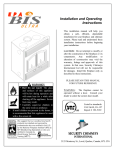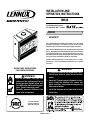
1
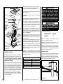
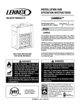
INSTALLATION AND
OPERATION INSTRUCTIONS
ME43
43" Wood Burning Fireplaces
P/N 850,027M REV. E 12/2007
MODEL
ME43BK SP
This installation manual will enable you to obtain a safe, efficient and
dependable installation of your fireplace system. Please read and
understand these instructions before beginning your installation.
Do not alter or modify the fireplace or its components under any circumstances. Any modification or alteration of the fireplace system, including
but not limited to the fireplace, chimney components and accessories,
may void the warranty, listings and approvals of this system and could
result in an unsafe and potentially dangerous installation.
Lennox™ wood-burning fireplaces are designed for use as a supplemental heater. They are not intended for continuous use as a primary
heat source.
RETAIN THESE INSTRUCTIONS
FOR FUTURE REFERENCE
WARNINGS
WARNINGS
• Hot! Do not touch! The glass and
surfaces of this appliance will be hot
during operation and will retain heat
for a while after shutting off the appliance. Severe burns may result.
• Carefully supervise children in the
same room as appliance.
• The fireplace cannot be operated without a door.
Consult your dealer to select the correct door
model.
• Important! To assure proper alignment of glass
doors: Install this fireplace in a square and
plumb condition, using shims as necessary at
sides and/or bottom.
• Install the fireplace only as described in these
instructions.
Listed to standards:
ULC-S610 & UL-127
Report No. 192-5166
PIME43-F REV. 3
IMPORTANT! GENERAL SAFETY
PRECAUTIONS. READ AND
UNDERSTAND THESE SAFETY
RULES BEFORE YOUR FIRST FIRE.
WARNING
Never leave children unattended
when there is a fire burning in
the fireplace.
IMPORTANT
When burning wood, use SOLID
NATURAL DRY WELL-SEASONED
WOOD ONLY. Hardwoods are
recommended (soft woods tend
to burn very quickly).
• DO NOT burn treated wood,
charcoal, coal, trash, cardboard, driftwood, woods dipped
in tar, Christmas tree greens,
pitch, pine tar, creosote, chemical chimney cleaners, flame
colorants, polystyrene packaging, wood products with synthetic
binders (i.e. plywood). Plywood,
lumber and other misc. materials can produce abnormally high
temperatures, sputtering and
smoking fires and may contain
hazardous chemicals to treat
insects and fungus.
• Burning unapproved fuels can
produce excessive temperatures, beyond the design capabilities of the fireplace and may
produce excess sparks or may
contain hazardous chemicals.
Burning unapproved fuels can
result in a chimney fire, a house
fire, personal injury, death or
loss of property.
WARNING
To avoid the risk of damaging
fireplace materials and increasing the risk of fire, do not use the
fireplace to cook or warm food.
CAUTION
NEVER use gasoline, gasolinetype lantern fuel, kerosene,
charcoal lighter fluid, naphtha,
engine oil or similar liquids to
start or “freshen up” a fire in this
fireplace. Keep any flammable
liquids a safe distance from the
fireplace at all times.
WARNING
The fireplace must be operated
with the doors fully opened or fully
closed. If the doors are left partly
opened, gas and flame may be
drawn out of the fireplace opening, creating risks of both fire and
smoke.
WARNING
Never leave your fireplace unattended while it is burning.
CAUTION
Use care when selecting window
treatments for windows located
near the fireplace. Avoid using
combustible flowing window
treatments such as curtains
on nearby windows that are of
sufficient length to be blown in
front of an open flame when the
window is opened.
Keep any combustible furniture,
materials or decorative pillows
at least 48" (1219 mm) from the
front fireplace opening.
WARNING
This fireplace has NOT been
tested with an unvented gas
log set. To reduce risk of fire or
injury, do not install an unvented
gas log set into this fireplace.
WARNING
Be careful adding wood fuel to the
fire or handling fireplace tools such
as shovels, tongs or pokers.
WARNING
Never modify or alter your fireplace system in any way. To do
so may create a potential fire
hazard and void the warranty,
listings and approvals of this
system.
WARNING
The bottom refractory can be
cracked by excessive abuse such
as tossing heavy logs onto the
grate or gouging with fireplace
tools. Exercise caution when
adding wood to your fireplace.
WARNING
Neither the manufacturer nor the
seller warrants “smoke free”
operation nor are we responsible
for inadequate system draft
caused by mechanical systems,
general construction conditions,
inadequate chimney heights,
adverse wind conditions and/or
unusual environmental factors or
conditions beyond our control.
WARNING
Always ensure that the air inlet to
the fireplace is free from debris
and any other obstructions that
can block the entrance of air.
WARNING
An outside air kit must be
installed on the ME43 fireplace.
Congratulations!
• This fireplace must be installed with Security
In selecting this LENNOX™ wood-burning appliance you have chosen one of the finest fireplaces available. The ME43 wood fireplace is a clean burning fireplace that is
designed to provide you dependable service as well as warmth and enjoyment for many
years to come.
Please carefully read and follow all of the instructions found in this manual. Please pay
special attention to the safety instructions provided in this manual. This information
will be useful to you now and in years to come, so keep the manual handy and refer to
it as needed.
Table of contents
Safety Rules........................................Page 2
Parts Required....................................Page 3
Optional Equipment.............................Page 3
Fireplace Maintenance
Creosote ............................................Page 4
Chimney maintenance.........................Page 4
Chimney fires......................................Page 4
Door Frame Care.................................Page 4
Glass cleaning.....................................Page 4
Doors adjustment...............................Page 4
Glass replacement...............................Page 4
Removal of ashes................................Page 4
Fireplace Operation
Fuel.....................................................Page 5
First fires.............................................Page 5
Building a fire......................................Page 5
Using the retractable
doors and firescreens.......................Page 5
How to use the outside air kit..............Page 5
Fireplace Installation
Pre-installation....................................Page 5
Tools and building supplies.................Page 6
Precautions.........................................Page 6
Installation procedure.........................Page 6
Locating the fireplace..........................Page 6
Adjacent walls.....................................Page 6
Enclosure............................................Page 6
Facing and mantel...............................Page 7
Hearth extension.................................Page 8
Outside air installation........................Page 8
UZY3 fan kit installation .....................Page 9
Framing Dimensions...........................Page10
Central forced air kit............................Page11
Chase Enclosure.................................Page11
Chimney System................................Page12
Installing the Chimney System............Page13
Offset Chimney Installation.................Page16
Chimney Component Chart.................Page17
Angled Wall Radiation Shield..............Page18
Universal Roof Support Installation....Page19
Multiple Terminations.........................Page19
Parts and Components........................Page20
Replacement Parts..............................Page22
Specifications......................................Page22
Clearances..........................................Page22
Product Reference Information...........Page24
SAFETY RULES FOR OPERATING
YOUR FIREPLACE
CAUTION
This appliance is designed for
use with wood or certified processed solid fuel fire logs. Do
not poke or stir the logs while
they are burning. Use only fire
logs that have been evaluated
for the application in fireplace
and refer to fire log warnings and
caution markings on packaging
prior to use.
• Use only Lennox Fireplace glass doors,
specifically designed for ME43 fireplace.
(See Page 22 for part numbers).
• Do not operate the fireplace with both
firescreens and doors closed at the same
time. Use the firescreen when doors are
fully opened.
• Always keep the fire screen or the doors
closed and the damper opened when using
the fireplace. Keep the damper closed when
the fireplace is not in use.
• The ME43 fireplace is sold with a steel log
grate. If you have to replace it, we recommend for optimum efficiency, to replace it
with an identical or similar Lennox model
grate.
• A fireplace insert heating unit may be installed
in the fireplace only if this unit has been
certified with the ME43 fireplace.
Chimneys™ ASHT+, S-2100+ or AC (8" inside
diameter) chimney System only. These systems are intended for use in any application
where a traditional masonry type fireplace
would apply. The chimney system must
always vent to the outside of the building.
• This fireplace has been tested for installation in Canada to CAN/ULC S610-M87 and
ANSI/UL 127-1996 under report number
192-5166. For installations in Canada, the
chimney clearance to combustibles must
be 2 inches and the Cold Climate Kit must
be installed.
• The minimum installed height of the
completed fireplace system is 15' 0". The
maximum height is 60' 0".
Parts Required
Fireplace Model ME43BK SP
• 8" diameter chimney - Model Secure Temp™
(ASHT 1"), Secure Temp (S-2100+) or AC manufactured by Security Chimneys International
only, including:
- Chimney lengths
- Elbows (where necessary)
- Associated components as per these
Installation Instructions
• Door (included)
• Outside Air Kit (included)
OPTIONAL EQUIPMENT
Additional Equipment (optional)
- Trim Kit and Door Capping available in
Nickel and Gold
- UZY5 blower
- VRUW Blower motor speed control
- Forced Air Heating Kit
FIREPLACE MAINTENANCE
Creosote
When wood is burned slowly, it produces tar
and other organic vapors which combine with
expelled moisture to form a black deposit called
creosote. The creosote vapors condense in the
relatively cool chimney flue of a slow burning
fire. As a result, creosote residue accumulates
on the flue lining. When ignited, this creosote
makes an extremely hot fire. If the creosote
accumulation is large, a creosote fire in the
chimney can damage the chimney and overheat the surrounding wood framing. Creosote
formation in a chimney can be minimized by
making small hot fires rather than slow burning,
smouldering fires.
Chimney maintenance
Regular chimney inspection and maintenance
combined with proper operation will help prevent chimney fires. Keep your chimney clean.
Do not allow more than a 1/16" (1.6mm) build-up
of creosote in your chimney. The amount of
creosote will depend on variables such as frequency of use and type of fire. We recommend
that you follow the instructions below:
1. Initially, inspect the chimney system weekly.
By doing this, you will learn how often it will be
necessary to clean your chimney.
2. Have your chimney cleaned by a qualified
chimney sweep. Chimney maintenance should
only be conducted by a qualified technical or
chimney sweep company.
3. Do not expect chemical cleaners to keep your
chimney clean.
6. Watch for smouldering or fire on combustibles
next to the fireplace and chimney. Check outside
to ensure that sparks and hot embers coming out
of the chimney are not igniting the roof.
7. Do not use the fireplace again until your
chimney and fireplace have been inspected by
a qualified chimney sweep or a fire department
inspector.
Door Frame Care
Use a glass cleaner and a soft cloth to polish
the frame. Do not use abrasives such as steel
wool or steel pads for they may scratch the
door frame finish.
Glass Cleaning
The ME43 fireplace is designed to keep the
glass clean under normal operating conditions. To clean the glass there are a number of
specially designed cleaners. Your authorized
LHP Dealer can recommend a suitable cleaner.
Regular household glass cleaners will not clean
creosote. Do not use abrasives such as steel
pads, steel wool or oven cleaner as they will
scratch the glass.
Doors Adjustment
Glass doors may lose their adjustment during
transportation or installation of the fireplace.
A wrong adjustment may cause a loss in
combustion’s efficiency and control. The glass
doors must be parallel, at the same height and
must almost touch each other when closed.
Maximum spacing between the doors is one
sixteenth of an inch (1/16’’).
The raincap can be removed for inspection
and/or cleaning of the chimney. Unscrew the
braces which attach the raincap to the chimney.
Using gloves, firmly grip the upper portion of
the rain cap. Turn the cap and lift it off the
chimney.
The glass doors can be adjusted by loosening
the three (3) screws of the hinges’ supports
(see fastening screws in Figure 1). If a minor
angular adjustment is needed, you may loosen
only two (2) of the three (3) screws using the
other as a pivot point.
Glass Replacement
The glass used for the ME43 fireplace doors is
a high temperature ceramic glass. If the glass
breaks, it must be replaced with a ceramic glass
such as Neoceram. Tempered or ordinary glass
will not withstand the high temperatures of
the ELITE ME43 fireplace. Replacement glass
should be purchased from your local LHP dealer.
Do not operate the unit with cracked or broken
glass. To remove the glass panel, unscrew the
frame screws, remove the interior frame and
the glass panel.
Removal Of Ashes
Remove ashes only when the fire is out and the
ashes are cold. Lift the front of the log grate
until it rests against the rear refractory; then
remove the ashes. Ashes should be placed in
a metal container with a tight-fitting lid. The
closed container of ashes should be placed on
a non-combustible floor or on the ground, well
away from all combustible materials, pending
final disposal. If the ashes are disposed of by
burial in soil or otherwise locally dispersed, they
should be retained in the closed container until
all cinders have thoroughly cooled. Do not leave
the ashes in the house as they give off carbon
monoxide and other toxic gases.
Fastening
Screws
Chimney fires
If you are having a chimney fire, follow these
steps:
1. Close the glass doors and the air inlet.
Frame
Screws
2. Close the chimney outside air register.
3. Alert your family of the possible danger.
4. If you require assistance, alert your fire
department.
5. If possible, use a dry chemical fire extinguisher, baking soda or sand to control the fire.
Do not use water as it may cause dangerous
steam explosions.
Interior Frame
Figure 1
NOTE: DIAGRAMS & ILLUSTRATIONS ARE NOT TO SCALE.
OPERATING THE fireplace
Fuel
The ME43 fireplace is designed to work best
when fueled with seasoned cordwood. Hardwoods are preferred to softwoods since the
energy content of wood is relative to its density.
Hardwoods will result in a longer burning fire
and less frequent refueling. A moisture content of 15% to 20% (seasoned) is preferred.
Excessively wet wood will be difficult to burn
and will result in lower efficiency and increased
creosoting.
How to use the retractable doors
and firescreens
The Lennox ME43 fireplace features retractable
doors and firescreens in order to allow a wider
view of the fire and save space when the doors
are opened. To retract the doors, simply open
them at 90° and push them into the opening
on the side of the firebox. The same procedure
applies for the retractable firescreens. (see
Figure 2).
Note : Do not operate the fireplace with both firescreen and doors closed at the same time.
Do not burn scrap or garbage, treated wood or
wood such as driftwood from the ocean which
has been exposed to salt or other chemicals.
Salt or chemicals can corrode the firebox and
chimney. Do not abuse the unit by burning
large amounts of paper, cardboard, Christmas
tree branches or building construction materials such as pressed wood, plywood or lumber.
Intense firing with these may overheat the
fireplace, causing damage to the unit, a fire,
or even possibly igniting a chimney fire, if the
chimney is creosoted.
The outside air register is located on the upper
part of the top louver. The outside air register
supplies oxygen to the fire and allows control
of the fire when the doors are closed. The fresh
air must come from outside the house (the
air intake must not draw air from inside the
house). This will minimize negative pressure
in the house. The more you slide the register
to the left, the more fresh air into the firebox
and the more accelerated combustion you will
get (see Figure 3). When starting a fire, the
register should always be fully opened.
FIREPLACE INSTALLATION
Preinstallation
Please Read Before Installing:
1.Before beginning the installation of your
fireplace, read these safety tips and installation instructions carefully to be sure you
understand them completely. Failure to
follow them could cause a fireplace malfunction resulting in serious bodily injury and/or
property damage.
First Fires
The first 5 or 6 fires should be small fires of
short duration (about 30-60 minutes). The first
fire should be especially short. This will help
cure the refractory bricks. The first fires may
produce slight smoking and some odor due
to drying of the paint and steel and any dust
accumulated on the fireplace will be burn off at
this time. For this reason the room should be
well ventilated during the first few fires.
How to use the outside air register
(fireplace)
2.The ME43 fireplace has been tested and listed
to UL and ULC standards by Warnock Hersey
International Inc. These instructions were
written to give you an outline for a fast and
safe installation and trouble-free operation.
Figure 2 PUSH TO
OPEN
Building A Fire
PUSH TO OPEN
To start a fire, place several crumpled up balls of
newspaper in the firebox. Place small dry pieces
of kindling on top of the paper, crisscrossing the
kindling so that there is airspaces in between.
Place the larger pieces of kindling on top of the
pile. Keep the fuel far back enough so that air
can get underneath. Open the air control fully
and light the newspaper. Once the kindling fire
is well established, cordwood can be added.
The unit will burn best with a minimum of two
pieces of cordwood spaced 1" to 2" apart and allowing air to get under the fuel. Crisscrossing or
arranging the fuel so that air can get underneath,
will help the fire to get started easily.
Figure 3
NOTE: DIAGRAMS & ILLUSTRATIONS ARE NOT TO SCALE.
Failure to use LHP parts or conduct variations
in techniques and construction materials
described in this installation manual may
create a serious fire hazard and may void
the warranty and the WHI listing.
3.Always check your local building codes.
The installation must comply with their
regulations. Before beginning the installation, consult the local authorities and
make sure your building permit complies
with their requirements.
4.This fireplace must be installed with Security
Chimneys™ chimney system models ASHT+,
S-2100+ or AC, of 8" inside diameter. These
systems are intended for use in any application where a traditional masonry type fireplace
would apply. The chimney system must
always vent to the outside of the building.
5.To maintain top efficiency and to prevent
build-up of soot and creosote, inspect and
clean the chimney periodically during the
heating season.
6.To prevent possible hazards due to poor
combustion and to avoid affecting other fuel
burning appliances (furnace, wood stove,
etc.), ensure that the outside air kit is properly
installed.
7.This fireplace is designed to allow the installation of a gas burner. In such a case, the
installation must conform with the National
Gas Code ANSI Z223.1 and Z21.60.
WARNING
When using a gas burner, it is
mandatory to keep the chimney
outside air register opened.
8.This fireplace has provision for the installation of a gas pipe and is intended only for
connection to a decorative gas appliance
incorporating an automatic shutoff device
and complying with ANSI Z21.60-M96/CGA
2.26-M96, Standard for Decorative Gas Appliances for Installation in Solid-Fuel Burning
Fireplaces (reference Clause 4.1.3 T).
9.The ME43 fireplaces are sold with factory
installed doors. The outside combustion
air kit is mandatory and is included with the
fireplace. Optional blowers and decorative
trims are available.
Tools And Building Supplies Normally
Required
Tools:
Phillips screwdriver
Slot style screwdriver
Hammer
Saw and/or Sabersaw
Level
Measuring tape
Plumb line
Electric drill and bits
Pliers
Square
If gas pipe is used:
Locating the LENNOX Fireplace
Do not place the fireplace on carpeting, vinyl
or other soft surface floor coverings. It may,
however, be directly placed on flat wood,
plywood, particle board or other hard surface
materials.
Adjacent wall
A wall perpendicular to and in front of the fireplace front facing must be at least 18" (460mm)
from the fireplace opening. A wall at 45º to the
front facing and starting at the fireplace’s outer
edge is permitted. Projections within this area
are permitted. See Figure 4.
Pipe wrench
Pipe cutter
Pipe threader
Pipe joint compound
Pipe key valve
STANDOFFS
WALL
FIREPLACE
Building supplies:
2" x 3" or heavier lumber
Drywall panel or equivalent
Silicone caulking (non-combustible)
Overlay material for fireplace façade
Hearth extension (non-combustible)
OPENING
45°
18"
(460mm)
precautions!
The most important areas of concern dealing
with the fireplace installation are clearances
to combustible materials, secure assembly of
components parts, the height of the chimney
system, the proper use of accessory equipment and the techniques used in using finishing materials applied to fireplace surrounds,
hearth extensions and wall coverings. Each
of these topics will be covered in greater detail
throughout this manual. Please give special
attention to these instructions as you progress
with your installation.
Fireplace Installation Procedure
1.Move the fireplace into the desired position
(follow the recommendations below for
enclosure).
2.Install the outside air assembly (or assemblies) - refer to Page 8.
3.Install the enclosure surrounding the fireplace (refer to the sections “Enclosure” below
and “ Facing and Mantel” on Page 7).
4.Install the hearth extension (see Page 8).
Make sure the gap between the fireplace
and the hearth extension is sealed.
NOTE: DIAGRAMS & ILLUSTRATIONS ARE NOT TO SCALE.
Figure 4
Enclosure
WARNING
Do not place loose insulation or
any other material in the space
around the fireplace or the
chimney. Insulation placed on
or around the fireplace or chimney may cause adjacent wood to
overheat and catch on fire.
1.The fireplace must be installed against a
finished wall (like drywall finish). It must
not be installed against a vapor barrier or
exposed insulation (see Figure 5).
2.Combustible materials like wood, plywood,
particle board or drywall can be in direct
contact with the fireplace standoffs. Two
inch (50mm) clearance to combustibles
must be kept around the chimney.
Fireplace Facing
WARNING
DRYWALL PANEL OR EQUIVALENT
The fireplace should be framed using 2" x 3"
(50mm x 75mm) or heavier lumber.
The top of the fireplace is not
zero clearance. Do not place
any insulating material in the
space above the fireplace for a
height of 7 feet from the base of
the fireplace.
2" x 3" MIN.
Figure 10 on Page 10 shows the general
framing layout.
Combustible materials must be installed
flush with the fireplace facing. They may not
project out in front of the fireplace. Noncombustible materials such as brick, stone or
ceramic tile, may project in front of and/or on
the fireplace facing.
3.Do not block the fireplace’s hot air vents or
air inlets as this will cause the fireplace to
overheat.
SPACER
FIREPLACE
Figure 6
WARNING
FLASHING
ROOF SUPPORT
NON COMBUSTIBLE
CHASE TOP
ATTIC
FIRESTOP
CEILING/FLOOR
SEPARATION
The header should rest on top
of the metal spacers. Do not
alter the spacers or notch the
header to fit around them. Do
not block the air inlet or outlet
as this will cause the fireplace
to overheat.
Mantel
MUST HAVE THE SAME FIRE RATING
AS ADJACENT CEILING.
2"
A wood mantel, if installed, must be at least
48" (1.2 m) above the base of the fireplace (see
Figure 7). There is no restriction regarding the
length or the width of the mantel.
MUST HAVE THE SAME INSULATION
AS ADJACENT CEILING.
LOCAL CODE REGULATION FOR CEILING
MUST BE APPLIED TO THE CEILING/FLOOR
SEPARATION, I.E. FIRESTOP, ETC.
7 ft. Min.
FINISHED
WALL
FIREPLACE
48"
Min.
8"
1"
52"
NOTE: Chase wall and floor must be insulated
in the same manner than the rest of the building
below the attic.
18"
Figure 7 Figure 5
NOTE: DIAGRAMS & ILLUSTRATIONS ARE NOT TO SCALE.
Hearth Extension Requirements
(refer to Figure 7)
A non-combustible hearth extension must
be built in front of the fireplace and extend
out on both sides. Hearth extensions must
be constructed according to the following
guidelines:
1. A layer of sheet metal 0.018" (0.45mm) thick
or 3/8" (9mm) thick insulating board or any
other material (tiles, marble, granite) with
equivalent heat resistance may be used.
Check with the local building authorities
before installing to determine what other
materials are acceptable in your area.
2.The hearth extension should be secured to
the floor. The gap between the fireplace and
the hearth extension must be sealed with
non-combustible caulking or cement.
3.On a raised base or raised hearth, a “Z” shape
piece of metal must be fabricated to join the
bottom of the fireplace to the floor.
Outside Air Installation
The outside air assembly must be installed
according to the following guidelines:
1.The maximum length of 4" I.D. (100 mm)
insulated flexible duct is 20 feet (6.1 m). If a
longer duct is required, use a 6" I.D. (150mm)
insulated flexible duct. The maximum length
is 40 feet (12 m). Refer to Figures 8B and
8C for connections.
2.The duct and register may be installed above
or below floor level.
3.The outside air register must not be installed
more than 7 feet (2.1 m) above the base of
the fireplace.
4.The outside air assembly must draw air from
outside the house. It must not draw air from
the attic, the basement or a garage.
5.Locate the outside register where it will be
well away from automobile exhaust fumes
or other vents.
6.The outside air register should be installed
where it is not likely to be blocked by snow
or exposed to extreme wind.
7.It is recommended to install the outside air
register at floor level. However, if you must
raise the air register above the fireplace level,
you will have to make a loop to the floor with
the flexible pipe to prevent from causing a
draft in the outside air register (see Figure
8 Detail A).
Outside Air Assembly
The outside air assembly is mandatory for
the fireplace.
7' MAX.
During operation, the fireplace requires air for
combustion and draws air out of the house. It
may starve other fuel burning appliances such
as gas or oil furnaces. As well, exhaust fans
and fan driven appliances may compete for
air, causing a negative pressure in the home,
resulting in smoke entering the home from
the fireplace. This situation is aggravated in
modern airtight houses.
LOOP IS MANDATORY
To overcome this potential problem, the
installation of an outside air assembly is
required to provide outside combustion air to
the fireplace.
(Detail A)
FIREPLACE
CONNECTION
OUTSIDE AIR CONNECTION
OUTSIDE AIR CONNECTION
TO THE FIREPLACE
OUTSIDE
INTAKE
ALUMINIUM
TAPE
ALUMINIUM TAPE
PLASTIC
COVER
SCREW
OPENING
FACING DOWN
WALL
FLEXIBLE
PIPE
PLASTIC COVER
FIREPLACE
(Detail B)
Figure 8
INSULATION
FLEXIBLE PIPE
NOTE: DIAGRAMS & ILLUSTRATIONS ARE NOT TO SCALE.
(Detail C)
Installation of the fan kit model
UZY3
NOTE: The fireplace must be electrically connected and grounded in accordance with local codes
or in the absence of local codes, with the current CSA C22.1 Canadian Electrical Code. For U.S.A.
installations, follow local codes and the National Electrical Code ANSI/NFPA No 70.
Note: This fan kit can easily be installed when
the fireplace has a pre-installed junction box.
You just have to plug them in.
CAUTION: Should this fan require servicing, the power supply must be disconnected.
Rating: 120 Volts, 60Hz, .63A.
These fans require periodic maintenance. Check the area in front of the fans and wipe or vacuum
at least once a month during the burn season.
The fans have magnetic blower mounts. The
junction box (factory installed on approved
fireplaces for the use of this fan kit) must be
connected to 110 VAC service before permanently enclosing the fireplace. The access hole
for connecting the 110 VAC is located on the
lower right exterior side of the fireplace.
Installation instructions:
1.
2.
3.
4.
5.
Open the bottom louver of the fireplace.
Place each fan kit into the fireplace side
opening 1" from the back of the fireplace.
Install the automatic fan activator on the
side of the firebox (the fan activator has
a magnetic mount).
Plug the fan kit into the junction box.
Ground both fans to the back panel using
the green screws (see Figure 9).
THERMODISC, AUTOMATIC
THERMAL FAN ACTIVATOR
FAN WITH
MAGNET
FAN WITH
MAGNET
CONNECTOR FOR
OPTIONAL RHEOSTAT
ELECTRICAL CONNECTION
WITH
GROUND CONNECTION
Figure 9
NOTE: DIAGRAMS & ILLUSTRATIONS ARE NOT TO SCALE.
Corner Installation
23-11/32”
(593mm)
Notes
J
D
Due to Lennox' ongoing commitment
to quality, all specifications, ratings
and dimensions are subject to change
without notice.
2" X 3"
MIN.
F
All framing dimensions calculated for
1/2" dry wall at the fireplace face. If
sheathing the chase or finishing with
other thickness materials, calculations
will need to be made.
* The fireplace must not be in contact with
any insulation or loose filling material.
Cover the insulation with Drywall panels
around the fireplace.
21-1/2”
(546mm)
E
Combustible materials can NOT be
used in the space directly above the
fireplace. Do not fill the space above
the fireplace with any material (Except
the wood framing)
G
Back Wall of Chase/Enclosure
Including Finising Materials if any
7' MIN.
OUTSIDE CHASE
B
A
C
L*
G
H
FRAMING DIMENSIONS
Fireplace Opening Width
Rough Framing Face
(unfinished shown)
A
42-1/2"
1080 mm
B
43-1/4"
1099 mm
Rough Framing Face (Unfinished Shown)
C
33"
838 mm
* Zero Clearance From Back Spacer to Wall
D
16-1/2"
419 mm
E
85"
2159 mm
F
42-1/2"
1080 mm
G
27"
686 mm
H
26"
660 mm
J
60-1/8"
1527 mm
K
8"
203 mm
L
1"
25 mm
Combustion
Air Kit
33”
(838mm)
10-5/8”
(270 mm)
27-1/2”
(699 mm)
K
43”
(1092 mm)
Knock-Out
for Ducting
42-1/2”
(1080 mm)
Outside Air
Intake
Knock-Out
for Ducting
43”
21-1/4
(540 mm) (1092 mm)
17-1/8”
(435 mm)
42”
(1067 mm)
28-5/16”
(719 mm)
36”
(914 mm)
Figure 10 - Framing Dimensions
10
NOTE: DIAGRAMS & ILLUSTRATIONS ARE NOT TO SCALE.
central forced air kit
The knock-outs provided on the sides of the
ME43 fireplace allow the connection of insulated
flexible pipe which enables you to heat adjacent
rooms up to 50 feet from the fireplace.
The ducting system must be installed as described below :
1. Fix the adaptor at the side of the fireplace by
twist-locking the adaptor to the fireplace.
You can use more than one outlet on the
fireplace (Figure 11).
2. Attach the 5" flexible pipe, using the collars provided. Important: Make sure that
the plastic wrapping around the flexible
pipe will not be in contact with the fireplace.
3. Route the flexible pipe to the chosen location. The ducting system can be installed
either in an upper room or in a lower
room.
4. Attach the flexible pipe to the fan, using
the collars (Figure 12).
5. Fix the decorative grill fan adaptor to the
fan.
6. Attach a standard 3" x 10" grill to the
adaptor.
7. Install the blower thermostat in that part
of the house to be heated by the hot air
duct. Do not install the blower thermostat
in the room where the fireplace is located.
A cooling thermostat can be installed in the
same room as the unit. This thermostat
will turn on the blower when the room
where the fireplace is located becomes
too hot.
INSULATED
FLEX PIPE
Figure 11
INSULATION
FAN
FLEX 5” O
ALUMINUM TAPE
COLLAR
Figure 12
This option requires electricity. Make sure that
the connections to the fan have been made
according to the local codes and comply with
their requirements. It is possible to connect
a flexible pipe to a central heating system.
Make sure the pipe will be connected to the
warm air supply duct, not to the return air
duct (Figure 13). Contact your local furnace
installer for installation guidelines.
FAN
5” O
INSULATED FLEX
NO-RETURN
VALVE
Chase Enclosure
A chase is a vertical box-like structure constructed to surround the fireplace and chimney. Refer
to Figure 14 for a typical chase configuration.
As with all chimney installations, avoid overhead
obstructions such as trees, power lines, etc.
A chase should be constructed and insulated
just like any outside wall. In a cold climate, we
recommend the base of the chase should also
be insulated between the solid continuous floor
beneath the fireplace and the chase bottom.
Chase insulation in a cold climate installation
is not required for safety.
AIR FLOW
FURNACE
Figure 13
NOTE: DIAGRAMS & ILLUSTRATIONS ARE NOT TO SCALE.
11
AC chimney should not be used in cold areas,
where temperatures are likely to fall below 32°
F (0° C), or altitudes above 4000 feet.
Insulate joists
Same As Ceiling
A chimney venting a fireplace shall not vent any
other appliance.
Draft Stops
The minimum system heights are indicated
in Table 1.
Firestop
In altitude, add 18" (450mm) to the chimney for
every 2000 feet (600 m) above sea level.
CTDT
Termination
All chimney installations must include at least
one support. The maximum length of chimney
that can be supported by the fireplace is 12 feet
(3.6 m) for S-2100+, 18 feet (5.4 m) for ASHT+
and 26 feet (8 m) for AC chimney.
Note: NonCombustible
Chase
Flashing
Must Be
Used To
Cover
Chase
Opening
The chimney must extend at least 3 feet
(915mm) above its point of contact with the
roof and at least 2 feet (610mm) higher than
any wall, roof or building within 10 feet (3 m)
of it (see Figure 15).
Optional
Insulation
In Outside
Walls Of
Chase
8'
Level
Solid
Continuous
Surface
Insulation
(Thermal Barrier)
Outside
Base
Figure 14
Chimney system
The ME43 fireplace is listed only with Security
Chimneys™ International Ltd. chimney systems, models ASHT+ 8", S-2100+ 8", or AC
8". Do not connect the fireplace to a masonry
chimney, chimney liner, or other brand of
factory-built chimney.
In areas with continuous temperatures below
0º F (-18º C), the use of an exterior chimney
increases the likelihood of operating problems
such as low draft, high rate of creosoting and
poor start up characteristics. Exterior chimneys are also prone to down-drafting and flow
reversal. Installations located in a basement,
in combination with outside chimneys, are
especially prone to flow reversal. In cold areas,
air cooled chimneys should not be used in an
exterior installation.
If the chimney extends higher than 5 feet
(1500mm) above its point of contact with the
roof, it must be secured using a roof brace
or guide wires.
A rain cap must be installed on top of the chimney. Failure to install a rain cap may cause the
fireplace to corrode and operate inefficiently.
Cut and frame square holes in all floors and
the roof to provide a 2" (50mm) clearance
between the chimney and any combustible
materials. Do not fill this 2" (50mm) space
with any material.
Portions of the chimney which may extend
through accessible spaces must be enclosed
to avoid contact with combustible materials or
damage the chimney.
Minimum System Heights
Fireplace Model
WARNING
If insulation is used, the fireplace
must not be placed directly
against it. Insulation or vapor
barriers, if used, must first be
covered with drywall panels,
plywood, particle board or other
material to assure insulation and
vapor barriers remain in place.
WARNING
Do not pack or fill required air
spaces with insulation or other
material. No material is allowed
in these areas.
*Construction Materials:
• framing materials
• particle board
• dry wall
• plywood
Note: 2" clearance to combustibles around
chimney components required.
Note: Do not insulate the chase cavity with
blown or fill type insulation materials.
Note: Local codes may not require firestopping
at the ceiling levels for outside chase installations. However, it is recommended for safety
and the reduction of heat loss.
Chimney Height
The total height of your completed fireplace
system from the surface the fireplace rests on to
the chimney top must not exceed 60' and must
also meet minimum height requirements. Refer
to the minimum system height chart.
ME43BK SP
Chimney Model
ASHT+ / S-2100+ / AC
Vertical Installation
15 feet (4.57 m)
One Offset (2 elbows)
18 feet (5.49 m)
Two Offsets (4 elbows)
20 feet (6.10 m)
2' min.
(610mm)
10' (3000mm)
Table 1
Figure 15
12
• paneling
• flooring
• etc.
NOTE: DIAGRAMS & ILLUSTRATIONS ARE NOT TO SCALE.
3' min.
(915mm)
CHIMNEY INSTALLATION
INSTRUCTIONS
STRAIGHT INSTALLATION
Cut and frame the holes in the ceiling, floor and
roof where the chimney will pass (see Figure
16). Use a plumb-bob to line up the center of
the holes. The hole sizes are indicated in Table
2 for the floor and ceiling holes and in Table 3
on Page 15 for the roof holes.
From below, install a firestop in each ceiling/
floor separation through which the chimney will
pass. At the attic level, install an attic radiation
shield from above (see Figures 17A & 17B).
For ASHT+ and S-2100+ chimneys, place the
first chimney length on the fireplace. To lock
it into place, turn 1/4 of a turn clockwise. With
the AC chimney you must use a starting section
before installing the first chimney length (see
Figure 18). Continue installing chimney lengths
until you reach the desired height.
Every time the chimney passes through a
roof or a wall, install the appropriate firestop.
When you reach the desired height, install the
roof support (see instructions included with
the support).
ATTIC
RADIANT
FIRESTOP
ASHT+ & S-2100+
Figure 17A
Then, put the roof flashing in place and seal
the joint between the roof and the flashing
with roofing pitch. For sloping roofs, place the
flashing under the upper shingles and on top of
the lower shingles. Nail the flashing to the roof,
using roofing nails (Figures 19A & 19B).
Figure 16
CHIMNEY MODEL
SQUARE HOLE
SIZE OPENING
ASHT+
14-3/8” (365 mm)
S-2100+ / HT6000+
16” (406 mm)
AC
15" (380 mm)
Note: See Table 3 for Sloped Roof Framing
Table 2 - Flat Roof Framing
Place the storm collar over the flashing and
tighten it with the bolt supplied. Finally, seal the
joint between the storm collar and the chimney,
using silicone caulking.
FIRESTOP
AC RSA
AC RS
AC
Figure 17B
Install the chimney cap. Once the chimney cap
is in place, the roof flashing can be washed
with a solvent or vinegar and then painted with
rust-proof paint.
NOTE: DIAGRAMS & ILLUSTRATIONS ARE NOT TO SCALE.
13
AC Model
(Air Cooled Insulated, Galvalume Chimney)
Rain Cap
Flashing Collar
Flashing
Support
Attic Radiation
Shield
Radiation
Shield
AC Air Cooled
Chimney Starting Piece
Cooling Air Kit
For Air Cooled
Chimney ACZI
Figure 18
14
Outside Combustion
Air Kit (UZI)
Note: The Outside
Air Kit is Mandatory
NOTE: DIAGRAMS & ILLUSTRATIONS ARE NOT TO SCALE.
CHIMNEY
COLLAR
SPACER
(BUILT INTO
FLASHING)
FLASHING
AC CHIMNEY
Figure 19B
Figure 19A
ROOF DOWN SLOPE HOLE SIZE
SLOPE
ASHT+
S-2100+
AC
8"
8"
8"
*
14-3/8" (365mm)
16" (406mm)
15" (380mm)
2/12
14-5/8" (371mm)
16-1/4" (413mm)
15-3/8" (390mm)
4/12
15-1/4" (387mm)
16-7/8" (429mm)
16-1/8" (410mm)
6/12
16-1/8" (410mm)
17-7/8" (454mm)
16-7/8" (430mm)
8/12
17-3/8" (441mm)
19-1/4" (489mm)
18-1/4" (465mm)
10/12
18-3/4" (476mm)
20-7/8" (530mm)
19-5/8" (500mm)
12/12
20-3/8" (518mm)
22-5/8" (575mm)
21-3/8" (545mm)
*cross slope hole size
Table 3
NOTE: DIAGRAMS & ILLUSTRATIONS ARE NOT TO SCALE.
15
OFFSET CHIMNEY INSTALLATION
ASHT+ and S2100+ Chimneys
AC chimney
The minimum chimney height (including
the fireplace) when using elbows is:
1. Install the first elbow. Turn it in
the required direction. Fasten it to
the chimney with the three (3) 1/2"
(12mm) metal screws provided.
2. Install the necessary lengths to achieve
the required offset. Lock the chimney
lengths together: it is recommended
to use three (3) 1/2" (12mm) screws.
If the offset length is made of two (2)
chimney lengths use an offset support
halfway up the offset. If penetrating
a wall, install a wall radiation shield
(see Figure 22).
3. Use another elbow to turn the chimney
vertically. Secure the elbow, using
three (3) 1/2" (12mm) screws.
4. Use a plumb-bob to line up the center
of the hole. Cut a hole for the chimney in the ceiling. Frame this hole as
described previously (see Page 12).
5. From below, install a radiation shield
(Figure 17A).
6. A support (ST+ or SO+) must be used
on the first 15’ section (5 m).
7. Continue with the regular installation.
1. Install the first elbow. Turn it in the
required direction. To lock it in place,
turn 1/8 of a turn. Fasten the straps attached to the elbow to the surrounding
framing using nails or drywall screws
(Figure 20).
2. Install the necessary chimney lengths
to achieve the required offset. Lock the
chimney lengths together. If penetrating a wall, use a wall radiation shield
(Figure 22).
3. Use another elbow to turn the chimney
vertically. Lock it to the chimney.
Fasten the straps attached to the elbow
to the surrounding framing using nails
or drywall screws.
4. Use a plumb-bob to line up the center
of the hole. Cut a hole for the chimney in the ceiling. Frame this hole as
described previously.
5. From below, install a radiation shield
(see Figure 17B).
6. Continue with the regular installation.
Fireplace
Model
Chimney Model
ME43BK SP
8" ASHT+/S-2100+/AC
Vertical
Installation
15 feet (4.57 m)
Two (2) Elbows
18 feet (5.49 m)
Four (4) Elbows
20 feet (6.10 m)
Table 4
After reaching the location requiring the
elbow, proceed as follows:
16
Note: An AC8SB starting section must be
used before installing an elbow.
30
15
ELBOW
30
15
ELBOW
45
30
15
ELBOW
4-1/4"
(108 mm)
20-1/4"
(514 mm)
9-1/2"
(241 mm)
24-1/4"
(641 mm)
13-1/2"
(343 mm)
21-1/4"
(540 mm)
3"
(156 mm)
16-1/2"
(419 mm)
7-1/2"
(190 mm)
20-3/4"
(527 mm)
10-1/2"
(267 mm)
18-1/2"
(470 mm)
DEVIATION
LENGTH
DEVIATION
LENGTH
DEVIATION
LENGTH
4"
(102 mm)
21-1/2"
(546 mm)
7-3/4"
(197 mm)
26"
(660 mm)
3"
(76 mm)
17-1/2"
(445 mm)
5-3/4"
(146 mm)
22-3/4"
(578 mm)
DEVIATION
LENGTH
DEVIATION
LENGTH
12"
4-13/16"
(122 mm)
27-11/16"
(703 mm)
9-3/8"
(238 mm)
25-3/4"
(654 mm)
---------------------------
DEVIATION
LENGTH
DEVIATION
LENGTH
DEVIATION
&
LENGHT
12"
8"
DEVIATION
&
LENGTH
12"
8"
DEVIATION
&
LENGTH
31"
(787 mm)
12-3/8"
(314 mm)
33-1/2"
(851 mm)
6-1/8"
(156 mm)
18"
ONE LENGTH BETWEEN ELBOWS
31-1/4"
(794 mm)
10-3/4"
(273 mm)
27-1/4"
(692mm)
5-3/4"
(146 mm)
18"
ONE LENGTH BETWEEN ELBOWS
25-1/2"
(648 mm)
17-3/4"
(451 mm)
29-1/2"
(749 mm)
12-1/2"
(318 mm)
26-1/4"
(667 mm)
5-3/4"
(146 mm)
18"
ONE LENGTH BETWEEN ELBOWS
46-1/2"
(1181 mm)
21-3/8"
(543 mm)
50-7/8"
(1292 mm)
11"
(280 mm)
36"
36-1/2"
(927 mm)
13-3/4"
(349 mm)
33"
(838 mm)
7-1/4"
(184 mm)
24"
29-3/4"
(756 mm)
22"
(559 mm)
34-3/4"
(883 mm)
15-1/2"
(394 mm)
32"
(813 mm)
7-1/4"
(184 mm)
24"
57"
(1448 mm)
27-3/8"
(695 mm)
62-1/2"
(1588 mm)
14-1/8"
(359 mm)
48"
47"
(1194 mm)
19-3/4"
(502 mm)
44-1/2"
(1130 mm)
10-1/4"
(260 mm)
36"
38-1/4"
(972 mm)
30-1/2"
(775 mm)
45"
(1143 mm)
21-1/2"
(546 mm)
43-1/2"
(1105 mm)
10-1/4"
(260 mm)
36"
DEVIATION
TOTAL LENGTH
Note: With the AC chimney, a starting length of 6" high must be used on top of the fireplace before installing
AC
8"
CHIMNEY
S-2100+
8"
CHIMNEY
ASHT+
8"
CHIMNEY
Table 5
17
-------
-------
-------
-------
---
52-3/4"
(1340mm)
23-1/2"
(597 mm)
51-1/4"
(1302 mm)
12"
(305 mm)
8" & 36"
43-1/4"
(1099 mm)
35-1/2"
(1260 mm)
51-1/4"
(1302 mm)
25"
(635 mm)
50-1/2"
(1276 mm)
12-1/4"
(311 mm)
8" & 36"
66"
(1676 mm)
32-5/8"
(829 mm)
61-1/2"
(1562 mm)
28-1/2"
(724 mm)
61"
(1550 mm)
14-3/4"
(375 mm)
18" & 36"
71-1/4"
(1810 mm)
35-5/8"
(905 mm)
78-7/16"
(1992 mm)
18-7/16"
(468 mm)
18" & 48"
33"
(838 mm)
86-7/8"
(2207 mm)
44-5/8"
(1134 mm)
95-3/4"
(2432 mm)
23"
(584 mm)
36" & 48"
66-3/4"
(1695 mm)
31-1/2"
(800 mm)
66-3/4"
(1695 mm)
16-1/4"
(413 mm)
24" & 36"
54-3/4"
(1391 mm)
46-3/4"
(1187 mm)
65-1/4"
(1657 mm)
TWO LENGTHS BETWEEN ELBOWS
72-5/8"
(1845 mm)
16-7/8"
(429 mm)
12" & 48"
56-1/4"
(1429 mm)
25-1/2"
(648 mm)
50-1/2"
(1283 mm)
42-1/2"
(1080 mm)
60"
(1524 mm)
30"
(762 mm)
16-1/4"
(413 mm)
24" & 36"
65-3/4"
(1670 mm)
TWO LENGTHS BETWEEN ELBOWS
55-1/4"
(1403 mm)
13-1/4"
(337 mm)
12" & 36"
46-1/4"
(1175 mm)
38-1/4"
(972 mm)
54-3/4"
(1391 mm)
27"
(686 mm)
60"
(1524 mm)
14-3/4"
(375 mm)
18" & 36"
TWO LENGTHS BETWEEN ELBOWS
54-1/4"
(1378 mm)
13-1/4"
(337 mm)
12" & 36"
97-1/4"
(2470 mm)
50-5/8"
(1286 mm)
107-3/8"
(2727 mm)
26-3/16"
(665 mm)
48" & 48"
77"
(1956 mm)
37-1/2"
(953 mm)
78-1/4"
(1988 mm)
19-1/4"
(489 mm)
36" & 36"
63"
(1600 mm)
55-1/4"
(1403 mm)
75-1/2"
(1918 mm)
39"
(991 mm)
77-1/2"
(1967 mm)
19-1/2"
(495 mm)
36" & 36"
AIR COOLED
ANGLED WALL RADIATION SHIELD
(RSM+, RSMI30, RSMI45)
CHIMNEY AC
ACRS
(RADIATION
SHIELD)
BRACE
STRAPS
When traversing a combustible wall with the
chimney at a 30° or 45° angle, an angled firestop
and/or wall radiation shield must be installed.
Only one is required (Figure 22). Table 6 gives
recommended hole size for installing a wall
radiation shield.
Note: 45° angle installation for Canada
only.
STRAPS
SUPPORT
In cold climate locations, we recommend that
you use the insulated wall radiation shield since
it will maintain the home’s thermal barrier.
RSM+ and RSMI30, RSMI45
Chimney
Model
Figure 20
RAIN CAP
STORM COLLAR
ROOF SUPPORT
Angle
Hole Size
ASHT+
8" I.D.
30º
14-3/8" x 36-1/2”
(365mm x 927mm)
Canada
Only
45º
14-3/8" x 24-3/4”
(556mm x 629mm)
S-2100+
8" I.D.
30º
16" x 40”
(406mm x 1016mm)
Canada
Only
45º
16" x 27-1/4”
(406mm x 692mm)
AC
8" I.D.
30º
15-1/4" x 38-1/4”
(365mm x 927mm)
Table 6
INSULATED WALL
FLASHING
INSULATED
WALL
FRAME 2” X 4”
OFFSET SUPPORT
DRYWALL
ANGLED INSULATED
WALL RADIATION SHIELD
ANGLE WALL RADIATION SHIELD
(INSULATED)
Figure 22
NOTE: IN COLD FREGIONS IT IS
RECOMMEDNED TO ENCLOSE THE
CHIMNEY IN AN INSULATED CHASE
Figure 21
18
NOTE: DIAGRAMS & ILLUSTRATIONS ARE NOT TO SCALE.
UNIVERSAL ROOF SUPPORT INSTALLATION
CHIMNEY CHASE AND MULTIPLE
TERMINATIONS
This support has three possible uses:
1. For ASHT+ and S-2100+ chimneys, it must be used on a roof to support the chimney.
2. It may be used on a floor, ceiling or roof above an offset to support the chimney above the
offset.
3. It may be used on a floor, ceiling or roof as a supplementary support when the chimney height
exceeds 15 feet (4.6 m.).
Table 7 gives maximum height of supported chimney.
NOTE: For the AC chimney, a support section (AC8SL) must be used every 40’ (12 m) instead
of the ST.
For roof support installation, refer to the instructions provided with the support.
For the purpose of this manual, a chimney chase
is considered a part of the chimney system
rather than part of a building. The termination
must be placed a minimum of 18" (460mm)
above the chase.
For installation where more than one chimney
is located in the same chase or within the same
general area, we suggest that their terminations be separated by at least 16" (410mm)
horizontally and 18" (460mm) vertically. This
separation is to prevent smoke migrating from
one chimney to another (see Figure 23).
UNIVERSAL OFFSET SUPPORT INSTALLATION
This support is used to support the chimney above an offset. When the chimney offset is used
to traverse a wall, this support may be used on the wall to support the chimney. The maximum
heights are given in Table 7. For offset support installation, refer to the instructions provided
with the support.
Maximum Height Of Supported Chimney
Chimney Model
Offset Support
Roof Support
ASHT+ 8" I.D.
20 feet (6.10 m)
24 feet (7.32 m)
S-2100+ 8" I.D.
14 feet (4.30 m)
16 feet (4.87 m)
AC 8" I.D.
40 feet (12.19 m)
50 feet (15.20 m)
Table 7
18" (460mm)
18" (460mm)
18" (460mm)
16"
(410mm)
16"
(410mm)
Figure 23
NOTE: DIAGRAMS & ILLUSTRATIONS ARE NOT TO SCALE.
19
ME43 COMPONENTS LISTS
Installation Accessories
Description
Forced Air Heating Kit
Cat./ Part No.
Outside Air Kit (Required - included with fireplace)
Outside Air Coupler to connect outside air UZI to fireplace,
UZIAD
UZIDF
Outside Air Ducting - includes 4" insulated flex x 10' long,
UZI
UZI
Starter Kit: For wall or furnace installations. Includes
blower (BISZY), flex adaptor and two clamps (BISAF),
blower variable speed control (VRUW), thermo disc (VTU),
blower flex adaptor (BISAVF), and back draft damper
(BISBD)
BISFWK-1
Flex - choose 15 feet or 25 feet depending on installation
Fireplace Options
Flex 5 inches ID x 15 feet Long
5FLEX15
Flex 5 inches ID x 25 feet Long
5FLEX25
Starter Kit Separate Components
Trim Kit - Gold
H3426
Trim Kit - Brushed Nickel
Blower flex adaptor, includes damper (BISBD)
BISAVF
H3395
Blower - 2 50 CFM
BISZY
Door Capping - Gold
H3393
Flex adaptor and two clamps for fireplace connection
BISAF
Door Capping - Brushed Nickel
H3394
Blower motor speed control
VRUW
Blower
UZY5
Thermo disc - turns motor on when fireplace hot and off
when cool
VTU
Blower motor speed control
VRUW
Back draft damper - prevents air blowing from furnace into
fireplace
BISBD
Options
Fireplace Model ME43 - Approved Venting Components
- 8” diameter chimney - Model ASHT+, S-2100+, HT6000+, HT6103+
or AC manufactured by Security Chimneys International only.
Notes:
1. (P rojet NovaTemp ) HT6000+ is equivalent to S-2100+
2. (Projet NovaTemp ) HT6103+ is equivalent to ASHT+
3. This appliance is equiped with the ASHT Chimney Adaptor. When other
chimney is used, a chimney adaptor for that chimney will be required.
4. Chimney Adaptor (S-2100+ / HT6000+) for CANADA ONLY - If you want to
install a S-2100+ / HT6000+ chimney, an adaptor is available (8UCA).
5. AC Chimney is Not recommended at elevations above 4000 feet or
in cold climates where temperatures are likely to fall below 32°F (0° C).
W hen using AC chimney, an AC8SB starter section must be used
before installing an elbow. W hen an offset is needed imm ediately off the
top of the fireplace, a starter section (AC8SB30) is available.
TM
TM
20
Heating/Cooling thermostat - 110 volt
HCTW
ME43 COMPONENTS LISTS
Secure TempTM ASHT+ High Temp. Insulated Stainless Steel Chimney
AC Chimney
8” Diameter, Listed to CAN/UCL-S604 & UL-103HT at 2100 F
(Air Cooled - 8” I.D.,13” O.D.)
Description
Part/Cat. No.
Description
Cat./Part No.
AC Starter Adaptors
Lengths & Misc. Chimney Components
An AC Adaptor Is Needed To Convert Fireplace For Use With AC Chimney
8” length, 8” Dia., 8L8
8L8
Starter Section (adaptor), 8” AC, AC8SB
H3801
12” length, 8” Dia., 8L12
8L12
Starter 30 Elbow, 8” AC, AC8SB30
H3802
18” length, 8” Dia., 8L18
8L18
24” length, 8” Dia., 8L24
8L24
36” length, 8” Dia., 8L36
8L36
48” length, 8” Dia., 8L48
8L48
Adjustable Length 12”, 8” Dia., 8LA
8LA
15 elbow, 8” Dia., 8E15
8E15
30 elbow, 8” Dia., 8E30
8E30
Rain Termination Cap, 8” Dia., 8CC
8CC
Wall Band
BM
Supports
Offset Support, SO
SO
Roof Support, ST
ST
Roof Brace, BS2
BS2
Firestops
Telescopic Attic Radiation Shield, 8TRS
Chimney Outside Air kit (Flex, Insulation, Outside
Register and coupling), ACZI
H1967
Lengths & Misc. Chimney Components
18” Length, 8” Dia. x 12” Long, AC6L18
H3798
36” Length, 8” Dia. x 36” Long, AC8L36
H3799
48” Length, 8” Dia. x 48” Long, AC8L48
H3800
15 Elbow, 8” Dia., AC8E15
H3795
30 Elbow, 8” Dia., AC8E30
H3796
Rain Termination Cap, 8” Dia., AC8CPR
H3794
Spark Arrester Screen (universal spark arrester band), PE+
PE
Wall Band, BM
H0484
Supports
Offset Support, SO
H0480
Support Section, AC8SL
H3804
Roof Support, ST
H0482
Roof Brace, BS2
H0483
8TRS
Firestop, 8BF
8BF
Radiation Shield, 8RS
8RS
Insulated Attic Radiation Shield, 8RSA
8RSA
Insulated Wall Radiation Shield, 8RSM
8RSM
Roof Flashings
Flat Roof Flashing, 8FR
8FR
1/12 - 7/12 (5 - 30 ), 8FAR
8FAR
8/12 - 12/12 (30 - 45 ), 8FBR
8FBR
Storm Collar, 8FC
Outside Air Kit
Required for AC chimney installation
8FC
Roof Flashings
Flat roof flashing, ACF
H0494
1/12 - 7/12 (5 - 30 ), AC, Adj. Roof Flashing, FA
H0495
8/12 - 12/12 (30 - 45 ), AC, Adj. Roof Flashing, FB
H0496
Storm collar, ACFC
H0500
Misc.
Telescopic attic radiation shield, ACRST
H0498
Firestop, ACBF
H0485
Radiation Shield, ACRS
H0486
21
ME43 COMPONENTS LISTS
Attic Radiation Shield, ACRSA
APPENDIX
H0487
Wall Radiation Shield, 30 , AC, RSM30
ACRSM30
Insulated Wall Radiation Shield, 30 , ACRSMI30
H0489
Chimney Outside Air Kit (Flex, Insulation, Outside
Register And Coupling), ACZI
H1967
Notes: AC Chimney is Not recommended at elevations above 4000 feet
or in cold climates.
PR-SR2028
Back refractory
PR-SR2027
Right side refractory
PR-SR2025D
Left side refractory
PR-SR2025G
Bottom refractory
PR-SR1722
Front refractory ash lip
PR-SR2026
Log Support Grate
PR-HELS43
Top louver
PR-SR15P
Bottom louver
PR-SR15P
Louver hinges
PR-PIVOT
Rigid firescreen (right)
PR-PARETIND-1
Black door (left)
PR-SR2060GNO
Black door (right)
PR-SR2060DNO
Gold plated door (left)
PR-SR2060GOR
Gold plated door (right)
PR-SR2060DOR
Ceramic glass panel
Snap disc, blower
Door gasket assembly
Damper
Touch-up paint, black
22
Part/Cat. No.
Refractory
Wooden handle
Weight
Height
Width
Depth
Chimney weight ASHT+
Chimney weight S-2100+
Chimney weight AC
343 lbs
42"
43"
26-5/8"
8.75 lb/feet
13.2 lb/feet
3.75 lb/feet
CLEARANCE TO COMBUSTIBLES
Replacement Parts
Description
SPECIFICATIONS
PR-SAC#69
PR-VC10
VTU
PR- GASKPORTEHE-1
PR-DAMPER43
90L73
The following clearances meet the minimum requirements for a
safe installation :
Side wall:
Ceiling:
18" (457mm)
7 feet (2135mm)
measured from the base of the fireplace
Fireplace enclosure:
Bottom: 0"
Side: 0"
Back: 0"
Top: Do not fill the space above the fireplace with any material (7 feet
measured from the base of the fireplace)
Chimney:
Mantel:
2" (50mm)
48" (1219mm) from the base of the fireplace
NOTES
23
Warranty
Your fireplace is covered by a limited warranty. Please read the warranty
to be familiar with its coverage.
Retain this manual. File it with your other documents for future reference.
Product reference information
We recommend that you record the following important information
about your fireplace. Please contact your Lennox Hearth Products dealer
for any questions or concerns. For the number of your nearest Lennox
Hearth Products dealer, please call 1-800-9-LENNOX.
Replacement parts
See Page 22 for a complete replacement parts list. Use only parts supplied from the manufacturer.
Normally, all parts should be ordered through your Lennox Hearth
Products distributor or dealer. Parts will be shipped at prevailing prices
at time of order.
When ordering repair parts, always give the following information:
1. The model number of the appliance.
2. The serial number of the appliance.
3. The part number.
4. The description of the part.
5. The quantity required.
6. The installation date of the appliance.
If you encounter any problems or have any questions concerning the
installation or application of this system, please contact your dealer.
LENNOX HEARTH PRODUCTS
1110 West Taft Avenue
Orange, CA 92865
Visit us at www.Lennox.com
Your Fireplace's Model Number_________________________________________
Your Fireplace's Serial Number_________________________________________
The Date On Which Your Fireplace Was Installed____________________________
Your Dealer's Name__________________________________________________
Your Dealer's Phone Number___________________________________________
The manufacturer reserves the right to make changes at any time, without notice, in design,
materials, specifications, prices and also to discontinue colors, styles and products.
Consult your local distributor for fireplace code information.
Printed in U.S.A. © 2005 by Lennox Hearth Products
24
P/N 850,027M REV. E 12/2007
1110 West Taft Avenue • Orange, CA 92865