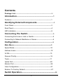
1
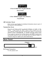
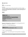
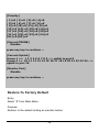
LevelOne
GSW-1601TX
GSW-2401TX
16/24Port 10/100Mbps Switch
with Gigabit option
User's Manual
(Vision 1.0)
FCC Class A Appliance
This equipment generates and uses radio frequency energy. If it is not
installed and used properly in strict accordance with the manufacturer‘s
instructions, it may cause interference to radio and television reception.
It has been type-tested and found to comply the specifications in
sub-part J of Part 15 of FCC Rules, which are designed to provide
reasonable protection against such interference in a residential
installation. There is no guarantee that interference will not occur in a
particular installation. If this equipment does cause interference to radio
or television reception which can be determined by turning the
equipment off and on, the user is encouraged to try to correct the
interference by one or more of the following measures:
Re-orient the receiving antenna
l Relocate the computing device with respect to the
receiver
l Move the computer away from the deceiver
l Plug the computer into a different outlet so that compute
and receiver are on different electrical circuits.
If necessary the user should consult the dealer or an experienced
radio or television technician for additional suggestions.
The information in this manual is subject to change without notice. All
the brand names are registered trademarks of their respective
companies
Contents
Package List---------------------------------------------------------------------- iii
Introduction---------------------------------------------------------1
Features------------------------------------------------------------------------------1
Identifying External Components---------------------------------3
Front Panel--------------------------------------------------------------------------3
Rear Panel---------------------------------------------------------------------------4
LED Indicators----------------------------------------------------------------------5
Connecting The Switch--------------------------------------------------5
Connecting End node or Hub or Switch--------------------------------------5
Connecting to Network Backbone or Server--------------------------------6
Configuration------------------------------------------------------8
Main Menu-------------------------------------------------------------------------9
Speed Mode-----------------------------------------------------------------------10
Address Learn---------------------------------------------------------------------12
VLAN--------------------------------------------------------------------------------13
Queues Priority-------------------------------------------------------------------16
Trunk--------------------------------------------------------------------------------17
Uplink Port-------------------------------------------------------------------------20
Monitor Port------------------------------------------------------------------------25
View Configuration---------------------------------------------------------------27
Restore To Factory Default----------------------------------------------------27
Switch Operation-----------------------------------------------------------28
i
Troubleshooting--------------------------------------------------30
Technical Specifications---------------------------------------31
RJ-45 Pin Specification----------------------------------------32
ii
Package List
Check the contents of your package for following parts:
l
16/24 Port 10/100Mbps Switch
l
User's manual
l
Power cord
l
19” rack mount brackets.
l
RS232 cable
If any of these pieces are missing or damaged, please contact your
dealer immediately, if possible, retain the carton including the original
packing material, and use them against to repack the product in case
there is a need to return it to us for repair.
iii
INTRODUCTION
The LevelOne GSW-1601/2401TX 16/24 Port 10/100/1000Mbps
Switch with Gigabit option is designed to allow simultaneous
transmission of multiple packets via an internal high-speed data
channel. This means that it can partition a network more efficiently than
bridges or routers in most environments.
The LevelOne GSW-1601/2401TX 16/24 Port 10/100/1000Mbps
Switch with Gigabit option is equipped with Category 5 copper cable or
fiber optic cable for uplinking to a network backbone or network server.
It is compatible with all 10Mbps, 100Mbps and 1000Mbps Ethernet
environments. The increased speed and extra bandwidth offered by
Gigabit Ethernet will support faster and more users applications with
generating more traffic.
In addition, the LevelOne GSW-1601/2401TX 16/24 Port
10/100/1000Mbps Switch with Gigabit option is also support one
module slot for 2 Ethernet Gigabit ports to uplink to a server or network
backbone. These Gigabit Switches are designed for Plug and Play
installation, allows the network administrator to simply connect the
network and power cables and the Switching/bridging functions begin
automatically.
The front panel of these Gigabit Switches provide LEDs for easy
recognition of the switch operation status and for troubleshooting.
These LEDs display the power status for the system and link/ speed/
collision, full-duplex, transmit and receive status for each port.
The built-in console interface can be used to configure the Switch’s
setting for Priority queuing, VLAN, and Port Trunk Groups, Port
Monitoring and Port Speed.
Features
l
l
l
Complies with the IEEE802.3 Ethernet, IEEE802.3u Fast Ethernet
and IEEE802.3z/ IEEE802.3ab Gigabit Ethernet standard
Provide a module slot for 2-port 10/100/1000T Gigabit Module
(copper model: MDU-0201T) and 2-port 1000SXGigabit Fiber
Module (fiber model: MDU-0200SX) option
Features Store-and-Forward mode with wire-speed filtering and
1
l
l
l
l
l
l
l
l
l
l
l
l
l
forwarding rates
Full/ Half-Duplex capability on each TX port, full duplex only on
1000Base-TX port
Automatic source address learning and aging.
Support up to 16K MAC address
Support up to total 64Mbit(16+2G), and 80Mbit (24+2G) packet
buffers
IEEE802.3x compliant full-duplex flow control, half-duplex flow
control
Broadcast storm control, runt and CRC Filtering eliminates
erroneous packets to optimize the network bandwidth
Support to handle up to 1536 bytes packet
Internal power supply
LED indicators for simple diagnostics and management
Auto MDI/ MDI-X on all 10/100/1000Base TX ports
Support one console port for switch configuration change
Support per port Port-based VLAN and L2 Trunking with link
fail-over
Support IEEE802.1p four Priority queues on each port
2
I DENTIFYING E XTERNAL COMPONENTS
This product series provide three different running speed – 10Mbps,
100Mbps, and 1000Mbps in the same hub and automatically
distinguish the speed of incoming connection.
This section describes the hardware features of these Gigabit
Switches. For easier management and control of the switch, familiarize
yourself with its display indicators, and ports. Front panel illustrations
in this chapter display the unit LED indicators. Before connecting any
network device to the hub, read this chapter carefully
There are two different module for expansion:
l
2 Port 10/100/1000T Gigabit Module
l
2 Port 1000SX Gigabit Fiber Module
Front Panel
The unit front panel provides a simple interface monitoring the
switching hub. It includes a power indicator for each port.
16 Port 10/100Mbps Switch with Gigabit option
24Port 10/100Mbps Switch with Gigabit option
16 Port 10/100Mbps Switch front panel
24 Port 10/100Mbps Switch front panel
3
2 Port 10/100/1000T Gigabit Module
Front Panel
2 Port 1000SX Gigabit Fiber Module
Front Panel
LED Indicator Panel
Refer to the next chapter for detailed information about each of
the switch’s LED indicators.
Twisted-Pair Ports
Use any of these ports to connect stations or hubs to the
switch. These ports are MDI-X ports, which means you can
use ordinary straight-through twisted-pair cable to connect the
switch to PCs, workstations, or servers through these ports.
If you need to connect to another device with MDI-X ports such
as another switch or hub, you should use a crossover cable, or
connect using the Uplink port (described below).
Rear Panel
16/24 Port 10/100/1000Mbps Switch with Gigabit option
AC Power Connector:
For the power cord.
4
LED Indicators
LED Indicators
LED Function
Color
Description
PWR
Green
Lit: Power on
SMART
Green
Lit: CPU installed
LINK/ACT
Green/Yellow
Green Lit: 100Mbps, indicates the adapter is
connected to hub and incoming
Yellow Flash: 10Mbps, traffic entering the port
10/100
Green
L10/100/1000
Lit: indicate link status and traffic speed
(10/ L10 for 10M, 100/ L100 for 100M,
1000/ L1000 for 1000M)
TX/ RX
Green
Lit: indicate data traffic status
(TX for transmitting, RX for receiving)
FDX/ COL
Green
Lit: Full-Duplex
Flash: Half-Duplex/ Collision
Off: Half-duplex or not connected
Reset Switch
At the left side of front panel, the reset switch is designed for
reconfiguring the switch hub without turn off and on the power.
C ONNECTING T HE S WITCH
Connecting End node or Hub or Switch
1.
Place the Switch on a smooth surface or fasten the mounting
brackets with the provided screws in a standard 19” rack
2.
Connect the DC jack of AC adapter to the DC inlet socket of
Switch and the other end into the local power source outlet
5
3.
Connect hub or PC to one port of the Switch using Category 3/4/5
UTP/STP cabling
4.
Connect another hub or PC to the other port of Switch by following
the same process as described in Step3.
Notice:
Cable distance for Switch
The cable distance between Ethernet Switch and hub/PC
should not exceed 100 meter; fiber cable distance shall not
exceed 220 meter.
Make sure the wiring is correct
It can be used Category 3/4/5 cable in 10 Mbps operation. To reliably
operate your network at 100Mbps and 1000Mbps, you must use an
Unshielded Twisted-Pair (UTP) Category 5 cable, or better Data Grade
cabling. While a Category 3 or 4 cable may initially seem to work,it
will soon cause data loss.
Connecting to Network Backbone or Server
Connect to the Gigabit Ethernet ports with Category 5 copper cable or
fiber optic cable for uplinking to a network backbone or network server.
These ports operate at 1000Mbps in full-duplex mode. A valid
connection is indicated when the Link LED is light. The following
sections describe the function of LEDs on the front panel.
CPU LED
Color: Green
Label: Smart
Function: The LED light up steadily means CPU installed for
smart function
Power LED
Color: Green
Label: PWR
Function: The LED light up steadily means Power turned on.
6
Link/ Speed LED
Color: Green
Label: L10/ L100/ L1000
Function: The LED light up steadily to indicate the transmitting
speed
L10: light up steadily to indicate link up at speed 10M
L100: light up steadily to indicate link up at speed100M
L1000: light up steadily to indicate link up speed 1G
Full/ Half Duplex and Collision LED
Color: Green
Label: FDX/ COL
Function: The indicator LED flash up whenever there is a
collision between a directly attached end node and any other
node, and light up steadily for Full-duplex mode.
TX Activity
Color: Green
Label: LINK/ ACT
Function: Each RJ45 station port on the hub is assigned one
LED for Transmitting the data
RX Activity
Color: Green
Label: LINK/ ACT
Function: Each RJ45 station port on the hub is assigned one
LED for receiving the data.
7
Configuration
Connect TO PC
RS-232 serial cable
Prepare a RS-232 serial cable. Attach the 9-pin female connector to
the male connector on the switch. Plug the other side of this cable to
your PC
Hyper Terminal
In Windows 95/98, launch “HyperTerminal”, create a new connection,
and adjust settings as below:
8
Main Menu
Launch the new terminal you just set up, and then, turn on the switch.
See the following messages for successful connection.
24-P 10/100M + 2-P 1G(COPER MODULE) switch
Configuration menu [ver:3.12]
[0] Port Setting
[1] Address Learn
[2] VLAN
[3] Queues Priority
[4] Trunk
[5] Uplink Port
[6] Monitor Port
[7] View Configuration
[8] Restore To Factory Default
Select :>>
To enter any of the submenus, simply type the number on the
command line.
9
Speed Mode
Entry:
Select “0” from Main Menu.
Purpose:
Media Speed Control for each port.
Default:
All ports are auto- negotiation.
1.Input port number for which you want to configure, ’A’ or ‘a’ for select
all port to configure, type ‘E’ or ‘e’ back to Main Menu, than press
ENTER. For example, input port 1:
which port ? (1 - 26 , 25=G1, 26=G2, E:Exit ,
A:Select all ports)...
1
Port Setting
[1] Auto-negotiation
[2] 10 Half Duplex
[3] 10 Full Duplex
[4] 100 Half Duplex
[5] 100 Full Duplex
Select :>>
2. Type 1-5 to select speed mode.
Select :>> 1
Enable flow control ? (Y/N)
3. Type ‘Y’ ,’y’ or ‘N’ ,’n’ to enable or disable flow control , After finish
flow -control selection, you can configure another port or type ‘E’ or
‘e’ , press ENTER back to main menu.
10
11
Address Learn
Entry:
Select “1” from Main Menu.
Purpose:
A port’s MAC address register is cleared on power-up, or hardware reset.
If this item is enabled, the dynamically learned SA will be leared if it is
not refreshed in less than the aging time.
Default:
Enable with aging time 5 minutes.
Select :>> 1
Aging Control
[E] Enable
[D] Disable
Example : Enable aging control with aging time 2 minutes.
1. type ‘E’ or ‘e’ to enable aging control
Select :>> e
Max address-aging timer
Max aging time (1 - 10 minute)...
2. input ‘2’ for aging time and back to main menu
12
VLAN
Entry:
Select “2” from Main Menu.
Purpose:
Each port of the switch can be assigned to one or multiple VLANs(this
device can be divided into 24 VLANs maximum). Frames from the
source port will only be forwarded to destination ports within the same
VLAN domain. A broadcast/multicast frame will be forwarded to all
ports within the VLAN(s) of the source port except the source port
itself.
An unicast frame will be forwarded to the destination port only if the
destination port is in the same VLAN as the source port. If the
destination port belongs to the another VLAN, the frame will be
discarded .Each port should be assigned with a dedicated uplink port.
Unicast frames with unknown destination addresses will be forwarded
to the uplink port of the source port. An uplink port can either be a
single port or a trunk.
Default:
All ports assigned to one VLAN.
Select :>> 2
VLAN
VLAN Group 1 ,assigned ports>>
[S] Port Select
[D] Port Delete
[A] Select All Ports
[C] Save
[E] Exit
Select :>>
Examples: Suppose the switch with 24 port , assigned port 1,2 to
VLAN group 1 ,port 5,6 belong to VLAN group 2 ,others be assigned to
VLAN group3 ,please follow below steps :
1. type ‘S’ or ‘s’ than input ‘1’ , press ENTER
13
Select :>> s
Which Port To be Selected (1 - 26)..., (25 = G1 26 = G2)
1
VLAN
VLAN Group 1 ,assigned ports>> 1
[S] Port Select
[D] Port Delete
[A] Select All Ports
[C] Save
[E] Exit
Select :>>
2. type ‘S’ or ‘s’ than input ‘2’ ,press ENTER
Select :>> s
Which Port To be Selected (1 - 26)..., (25 = G1 26 = G2)
2
VLAN
VLAN Group 1 ,assigned ports>> 1 2
[S] Port Select
[D] Port Delete
[A] Select All Ports
[C] Save
[E] Exit
3. type ‘C’ or ‘c’ , than you can see “Group 1 >> 1 2” on the
screen ,that means VLAN group 1 with port 1,2 completed
14
Select :>> c
Please Wait !!
VLAN
Group 1 >> 1 2
VLAN Group 2 ,assigned ports>>
[S] Port Select
[D] Port Delete
[A] Select All Ports
[C] Save
[E] Exit
Select :>>
4. repeat step 1 through 3 but input ‘5’ and ‘6’ to assigned [port 5 ,6 ] to
next VLAN group ,than you can see the result below
VLAN
Group 1 >> 1 2
Group 2 >> 5 6
VLAN Group 3 ,assigned ports>>
[S] Port Select
[D] Port Delete
[A] Select All Ports
[C] Save
[E] Exit
Select :>>
5. type ‘E’ or ‘e’ will assigned others to VALN group 3 and back to main
menu.
6. assigned with a dedicated uplink port for each VLANs, please refer
to section of “Uplink Port”
15
Queues Priority
Entry:
Select “3” from Main Menu.
Purpose:
The switch can support priority either from tagged frame or based on
the input ports. This entry is for port-based priority, level 0 stand for the
lowest priority, level 7 as highest priority. Flow control will be disable if
priority level 7 was selected .
Default:
All ports are cleared to priority zero on power-up, or hardware reset.
Select :>> 3
which port ? (1 - 24 , E:Exit )...
Example : Set port 1 to priority level 7.
1.
input ‘1’ for select port
1
Priority level ? (0 - 7 , E:Exit )...
2. input ‘7’ priority level
7
which port ? (1 - 24 , E:Exit )...
3. type ‘E’ or ‘e’ back to main menu
16
Trunk
Entry:
Select “4” from Main Menu.
Purpose:
This switch can assigned port 1 – 8 to trunk 0 or trunk 1,port 9 – 16 to
trunk 2 or trunk 3 , port 17 – 24 to trunk 4 or trunk 5, with L2 Trunking
automatically load-balances among its member ports through the use
of unique and statistical methods, and provides link resiliency
(link-fail-over function) when one or more of the link in a trunk group
fails.
Default:
All trunks disable.
Select :>> 4
Trunk
Which Trunk
[0] Trunk 0 (Disable)
[1] Trunk 1 (Disable)
[2] Trunk 2 (Disable)
[3] Trunk 3 (Disable)
[4] Trunk 4 (Disable)
[5] Trunk 5 (Disable)
[6] Trunk 6 (Disable) [Giga]
[E] Exit
Examples: Suppose the switch with 24 port , assigned Trunk 0 with 3
ports member ,Trunk 2 with 8 ports member. follow below steps :
1. type ‘0’ to start trunk 0 setting
17
Select :>> 0
Trunk 0 ,member >>
[A] Add
[D] Delete
[C] Setting
[E] Exit
2. type ‘A’ or ‘a’ three times to assigned trunk port member
Trunk 0 ,member >>port 1 2 3
[A] Add
[D] Delete
[C] Setting
[E] Exit
Select :>>
3. type ‘C’ or ‘c’ to finish setting
Select :>> c
Please Wait !!
Which Trunk
[0] Trunk 0 (1 2 3 )
[1] Trunk 1 (Disable)
[2] Trunk 2 (Disable)
[3] Trunk 3 (Disable)
[4] Trunk 4 (Disable)
[5] Trunk 5 (Disable)
[6] Trunk 6 (Disable) [Giga]
[E] Exit
4. Repeat step 1-3 but select trunk 2 and type ‘A’ or ‘a’ 8 times
18
Trunk 2 ,member >>port 9 10 11 12 13 14 15 16
[A] Add
[D] Delete
[C] Setting
[E] Exit
Select :>> c
Please Wait !!
Which Trunk
[0] Trunk 0 (1 2 3 )
[1] Trunk 1 (Disable)
[2] Trunk 2 (9 10 11 12 13 14 15 16 )
[3] Trunk 3 (Disable)
[4] Trunk 4 (Disable)
[5] Trunk 5 (Disable)
[6] Trunk 6 (Disable) [Giga]
[E] Exit
5. type ‘E’ or ‘e’ return to main menu
19
Uplink Port
Entry:
Select “5” from Main Menu.
Purpose:
The uplink port provides a way to connect the switch with a repeater
hub, a workgroup switch, a router, or any type of interconnecting
device compliance with IEEE 802.3 standards. Switch will send all
frames with unmatched DA and multicast/broadcast frames to the
uplink port. It is very important that each port is assigned to an uplink
port, or data frames might be lost. The uplink port should be configured
to be within the same VLAN as the source port. If the uplink port is not
a member of the VLAN, the broadcast or multicast frames will not be
forwarded to its designated uplink port. Multiple VLANs can share the
same uplink port.
Default:
Disable
Select :>> 5
Uplink Port
UpLink Group 1 ,assigned ports>>
[S] Port Select
[D] Port Delete
[A] Select All Ports
[C] Continue
[E] Exit
Example : assume already configure two VLANs ,VLAN A have port
1 ,2 ,3 ,4 ,5, 6,7,8,9. others belong to VLANs B .assign uplink port 9 for
VLANs A ,port 10 for VLAs B.
1. type ‘S’ or ‘s’ to select port
Select :>> s
Which Port To be Selected (1 - 26)..., (25 = G1 26 = G2)
2. input ‘1’ and press ENTER
20
1
Uplink Port
UpLink Group 1 ,assigned ports>> 1
[S] Port Select
[D] Port Delete
[A] Select All Ports
[C] Continue
[E] Exit
Select :>>
3. repeat step 1,2 to select port 2,3,4,5 ,6,7,8,9 ,then see the result
below.
UpLink Group 1 ,assigned ports>> 1 2 3 4 5 6 7 8 9
[S] Port Select
[D] Port Delete
[A] Select All Ports
[C] Continue
[E] Exit
Select :>>
4. type ‘C’ or ‘c’ to continue
Select :>> c
Please Wait !!
Uplink Port Select
[A] port 1 [B] port 2 [C] port 3 [D] port 4 [E] port 5
[F] port 6 [G] port 7 [H] port 8 [I] port 9 [J] port 10
[K] port 11 [L] port 12 [M] port 13 [N] port 14 [O] port 15
[P] port 16 [Q] port 17 [R] port 18 [S] port 19 [T] port 20
[U] port 21 [V] port 22 [W] port 23 [X] port 24 [Y] port G1
[Z] port G2
Select :>>
5. type ‘I’ or ‘i’ to select uplink port ,as you can see bellow, “Group 1 >>
1 2 3 4 5 6 7 8 9 --> uplink to port 9” means port 1,2,3,4,5 ,6,7,8,9,have
uplink to port 9.
21
Select :>> e
Uplink Port
Group 1 >> 1 2 3 4 5 6 7 8 9 --> uplink to port 9
UpLink Group 2 ,assigned ports>>
[S] Port Select
[D] Port Delete
[A] Select All Ports
[C] Continue
[E] Exit
Select :>>
6. repeat steps1 –5 to assign others to uplink port 10 ,as
result below:
Select :>> j
Uplink Port
Group 1 >> 1 2 3 4 5 6 7 8 9 --> uplink to port 9
Group 2 >> 10 11 12 13 14 15 16 17 18 19 20 21 22 23 24
-->
uplink to port 10
UpLink Group 3 ,assigned ports>>
[S] Port Select
[D] Port Delete
[A] Select All Ports
[C] Continue
[E] Exit
Select :>>
7. type ‘E’ or ‘e’ back to main menu
22
Link to another switch via signal port or TRUNK port
Please create a uplink port for any port or trunk-port you want
to cross link to another switch, there is a example for 16 + 2G
cross link via G1 port ,refer to the steps under :
16-P 10/100M + 2-P 1G(COOPER MODULE) [ver:3.12]
[0] Port Setting
[1] Address Learn
[2] VLAN
[3] Queues Priority
[4] Trunk
[5] Uplink Port
[6] Monitor Port
[7] View Configuration
[8] Restore To Factory Default
Select :>> 5
Uplink Port
UpLink Group 1 ,assigned ports>>
[S] Port Select
[D] Port Delete
[A] Select All Ports
[C] Continue
[E] Exit
Select :>> a
Please Wait !!
23
UpLink Group 2 ,assigned ports>>
[S] Port Select
[D] Port Delete
[A] Select All Ports
[C] Continue
[E] Exit
Select :>>e
24
Monitor Port
Entry:
Select “6” from Main Menu.
Purpose:
The switch supports port monitoring. This feature provides complete
network monitoring capability at 100 Mbit/s. A copy of egress (TX) data
and ingress (RX) data of the monitored port is sent to their respective
snooping ports.
Default:
Disable
Select :>> 6
Monitor Port
[M] Monitored Port
[I] Monitoring Port for Incoming Packets
[O] Monitoring Port for Outgoing Packets
[D] Disable Port Monitor
[E] Exit
Select :>>
Example : Monitored Port 1 , Monitoring for incoming packets port 2,
Monitoring for outgoing packets port 3.
1. type ‘M’ or ‘m’ to select Monitored Port
Select :>> m
Which port to be monitored (1 - 24)...
2. input ‘1’ and press ENTER
3. repeat step1 –2 for monitoring port incoming packets and outgoing
packets.
25
4. type ‘E’ or ‘e’ back to main menu.
26
View Configuration
Entry:
Select “7” from Main Menu.
Purpose:
Diplay configuration of port setting,address
learn,VLAN,priority,trunk,uplink port, monitor port.
Select :>> 7
[Port Setting]
F:full duplex ,H:half duplex ,Y:flow control enable ,N:flow
control disable
[ 1] Auto /Y [ 2] Auto /Y [ 3] Auto /Y [ 4] Auto /Y
[ 5] Auto /Y [ 6] Auto /Y [ 7] Auto /Y [ 8] Auto /Y
[ 9] Auto /Y [10] Auto /Y [11] Auto /Y [12] Auto /Y
[13] Auto /Y [14] Auto /Y [15] Auto /Y [16] Auto /Y
[17] Auto /Y [18] Auto /Y [19] Auto /Y [20] Auto /Y
[21] Auto /Y [22] Auto /Y [23] Auto /Y [24] Auto /Y
[G1] Auto /Y [G2] Auto /Y
[Address Learn]
aging times = 5 minutes
press any key to continue ...
[Current VLAN]
Group 1 >> 1 2 3 4 5 6 7 8 9 10 11 12 13 14 15 16 17 18 19 20
21 22 23 24 G1 G2
press any key to continue ...
27
[Priority]
[ 1]=0 [ 2]=0 [ 3]=0 [ 4]=0
[ 5]=0 [ 6]=0 [ 7]=0 [ 8]=0
[ 9]=0 [10]=0 [11]=0 [12]=0
[13]=0 [14]=0 [15]=0 [16]=0
[17]=0 [18]=0 [19]=0 [20]=0
[21]=0 [22]=0 [23]=0 [24]=0
[G1]=0 [G2]=0
[Current TRUNK]
Disable
press any key to continue ...
[Current UpLink]
Group 1 >> 1 2 3 4 5 6 7 8 9 --> uplink to port 9
Group 2 >> 10 11 12 13 14 15 16 17 18 19 20 21 22 23 24 -->
uplink to port 10
[Monitor Port]
Disable
press any key to continue ...
Restore To Factory Default
Entry:
Select “8” from Main Menu.
Purpose:
Restore to the default setting as mention before.
28
Switch Operation
Address Table
The LevelOne 16/24 Port 10/100/1000Mbps Switch with Gigabit option
is implemented with an address table. This address table composed of
many entries. Each entry is used to store the address information of
some node in network, including MAC address, port no, etc. This
information comes from the learning process of Ethernet Switch..
Learning
When one packet comes in from any port. The LevelOne 16/24 Port
10/100/1000Mbps Switch with Gigabit option will record the source
address, port no. and the other related information in address table.
This information will be used to decide either forwarding or filtering for
future packets.
Forwarding & Filtering
When one packet comes from some port of the Ethernet Switching, it
will also check the destination address besides the source address
learning. The Ethernet Switching will lookup the address-table for the
destination address. If not found, this packet will be forwarded to all the
other ports except the port which this packet comes in. And these ports
will transmit this packet to the network it connected. If found, and the
destination address is located at different port from this packet comes
in, the Ethernet Switching will forward this packet to the port where this
destination address is located according to the information from
address table. But, if the destination address is located at the same
port with this packet comes in, then this packet will be filtered. Thereby
29
increasing the network throughput and availability
Store-and-Forward
Store-and-Forward is one type of packet-forwarding techniques. A
Store-and Forward Ethernet Switching stores the incoming frame in an
internal buffer, do the complete error checking before transmission.
Therefore, no error packets occurrence, it is the best choice when a
network needs efficiency and stability.
The Ethernet Switch scans the destination address from the
packet-header, searches the routing table provided for the incoming
port and forwards the packet, only if required. The fast forwarding
makes the switch attractive for connecting servers directly to the
network, thereby increasing throughput and availability. However, the
switch is most commonly used to segment existing hubs, which nearly
always improves overall performance. A Ethernet Switching can be
easily configured in any Ethernet network environment to significantly
boost bandwidth using conventional cabling and adapters.
Due to the learning function of the Ethernet switching, the source
address and corresponding port number of each incoming and
outgoing packet are stored in a routing table. This information is
subsequently used to filter packets whose destination address is on
the same segment as the source address. This confines network traffic
to its respective domain, reducing the overall load on the network.
The Gigabit Switch performs "Store and forward" therefore, no error
packets occur. More reliably, it reduces the re-transmission rate. No
packet loss will occur.
Auto-Negotiation
The STP ports on the Gigabit Switch have built-in “Auto-negotiation”.
This technology automatically sets the best possible bandwidth when a
connection is established with another network device (usually at
Power On or Reset). This is done by detect the modes and speeds at
the second of both device is connected and capable of, Both 10Base-T
and 100Base-TX devices can connect with the port in either Half- or
Full-Duplex mode. 1000Base-TX and 1000Base-SX can only
connected Full-duplex mode.
30
Troubleshooting
This chapter contains information to help you solve problems. If
LevelOne GSW-1601/2401TX 16/24 Port 10/100/1000Mbps Switch
with Gigabit option is not functioning properly, make sure the
Ethernet Switch was set up according to instructions in this manual..
l
The Link LED is not lit
Solution:
Check the cable connection and remove duplex mode of LevelOne
GSW-1601/2401TX 16/24 Port 10/100/1000Mbps Switch with Gigabit
option
l
Some stations can not talk to other stations located on the other
port
Solution:
The address table may contain older information than of the address
table of that node. Please power down to refresh the address
information.
31
T ECHNICAL S PECIFICATIONS
l
l
l
l
l
l
l
l
l
Standard: IEEE802.3. IEE802.3u, IEEE802.3z, IEEE802.3ab
Network Media:
10Base-T – UTP/STP category 3 or 5 cable
100Base-TX – UTP/STP category 5 cable
1000Base-TX, 4 pairs category 5 cable
1000Base-SX, Multi-mode 62.5/125µm fiber optic cable
Connector: STP RJ-45 port TX
SC connector for 1Gbps FX
LED indicators:
System – Power OK LED.
Individual port:
10/100Mbps TX ports– link/activity, speed, duplex and collision
LEDs
Gigabit copper port: Link1000, Link 100, Link 10, FDX/Col,,
TX, RX activity LEDs
Gigabit port: Link, Activity LEDs
Dimension: 440mm x 245mm x 45mm
Temperature: Operating – 0? to 50? Storage – -20? to 70?
Humidity: Operating – 10% to 90% RH
Storage – 5% to 90%
RH
Input Power Requirement: 100 - 240VAC, 50 – 60Hz,
Auto-sensing
Registrations: FCC Part 15 Class A, CE
32
RJ-45 P IN S PECIFICATION
When connecting your LevelOne GSW-1601/2401TX 16/24 Port
10/100/1000Mbps Switch with Gigabit option to another switch, a
bridge or a hub, a modified crossover cable is necessary. Please
review these products for matching cable pin assignment.
The following diagram and tables show the standard RJ-45
receptacle/connector
and
their
pin
assignments
for
the
switch-to-network adapter card connection, and the straight / crossover
cable for the Switch-to-switch / hub / bridge connection.
RJ-45 Connector pin assignment
Contact
Media Direct Interface Signal
1
TX + (transmit)
2
TX - (transmit)
3
Rx + (receive)
4
Not used
5
Not used
6
Rx - (receive)
7
Not used
8
Not used
The standard cable, RJ-45 pin assignment
The standard RJ-45 receptacle/connector
33
The following shows straight cable and crossover cable connection:
Straight cable for Switch (uplink MDI-II port) to switch/Hub or
other devices connection
Crossover cable for Switch (MDI-X port) to switch/hub or other
network devices (MDI-X port) connection
34