1
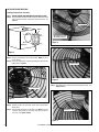
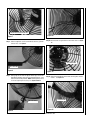
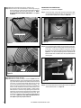
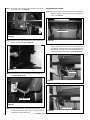
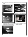
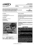
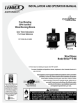
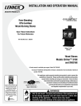
HEARTH PRODUCTS
KITS AND ACCESSORIES
P/N 506033-35
Rev. NC, 11/2009
FREESTANDING BLOWER Snap switch RETROFIT KIT
COUNTRY COLLECTION™ WOODSTOVES
INSTALLATION INSTRUCTIONS FOR INSTALLING A BLOWER snap switch
RETROFIT kit for use with COUNTRY COLLECTION™ MODELS S160, SA160,
SS210, ST210, S260 AND ST310 FREESTANDING WOODSTOVES
KIT CONTENTS
GENERAL INFORMATION
1 ea.Blower Wire Harness (item #1)
1 ea. Snap Switch and Control Panel Housings (item #2)
1 ea. 6” of 3/4” Heat Shrink Tube (item #3)
2 ea. Butt Connectors (item #4)
3 ea. Wire Ties (item #5)
1 ea. Instruction Sheet
This retrofit kit works in conjunction with the optional 700-CFM room air
circulation blower kit. The kit provides a variable speed control (rheostat)
and snap switch, which will allow for the option of automatic thermal
activation of the blower, when desired and blower speed control (see
Blower Operation on Page 8).
TOOLS NEEDED
If you encounter any problems, need clarification of these instructions or
are not qualified to properly install this kit, contact your local distributor
or dealer.
Read this instruction sheet in its entirety before beginning the installation.
5/32 Allen Wrench Or T Handle Wrench
Cutting Pliers
Wire Crimpers
9/16” Socket Wrench
9/16” Open End Wrench
Crescent Wrench
3/8” End Wrench
Large Flat Head Screwdriver
ALL WARNINGS AND PRECAUTIONS IN THE INSTALLATION AND
OPERATION MANUAL PROVIDED WITH THE APPLIANCE APPLY TO
THESE INSTRUCTIONS.
SHUT DOWN THE STOVE AND ALLOW IT TO COMPLETELY COOL BEFORE
PROCEEDING.
WARNINGS
The blower must be plugged directly into a properly
grounded three-prong receptacle, 120 VAC, 60 Hz, single
phase. Do not cut or remove the grounding prong from
this plug. Do not route power cord under or in front of
appliance.
2
5
3
Installation must be in accordance with National Electrical Code, ANSI/NFPA 70 - latest edition. In Canada,
the current CSA C22-1 Canadian Electrical Code - latest
edition.
4
1
DANGER: Disconnect power before servicing blower.
Figure 1 - Kit Contents
FREESTANDING BLOWER SNAP SWITCH RETROFIT KIT
Cat. No.
Model
H7918
SSK-BLWR-FSB700
Description
Blower Retrofit Kit, FS Woodstoves
In the event that you remove the blower for any reason,
make sure a cover plate (available from Lennox Hearth
Products) is installed before using the heater. Excessive
rear wall temperatures will result if the stove is burned
without the cover plate. The cover plate is not necessary
if a blower has never been installed because a knock-out
will be in place to act as the cover.
NOTE: DIAGRAMS & ILLUSTRATIONS ARE NOT TO SCALE.
Installation Instructions
Removing Existing Blower From Stove
Step 1. UNPLUG POWER CORD AND ENSURE APPLIANCE IS COLD
Step 2. Using a 5/32 allen wrench/T-handle, remove the blower mounting
allen screws from blower, and remove blower from stove. See
Figure 2.
Butt Connectors
Blower
Cut black wires on motor
side of butt connectors
Figure 4
Stove Back
Figure 2
Step 3.Using a crescent wrench, remove the fan blade. NOTE: Fan nut is
reverse thread.
Step 4.Using a 3/8” end wrench, remove the ground (green) wire from the
blower stud. See Figure 3.
Cut Wires Shown
Figure 5
Green Ground Wire
Step 7. Strip blower wires and connect butt connectors to both. See
Figures 6 and 7.
Figure 3
Step 5. Carefully remove the black heat shrink sleeve material from
blower wires.
Step 6. Cut both butt connectors on the motor side. Note: Cut at the
connector being careful to not remove any more wire than is
necessary. See Figures 4 and 5.
Strip wires as shown
Figure 6
NOTE: DIAGRAMS & ILLUSTRATIONS ARE NOT TO SCALE.
Crimp on butt connectors to both wires
Figure 10
Figure 7
Step 8. Slide the supplied 6” of 3/4” heat shrink tube over the (3) blower
harness wires. See Figure 8.
Step 10.Reconnect the new ground wire to the motor stud. See Figure
11.
Green Ground Wire
Heat shrink tube
Figure 8
Figure 11
Step 9. Placing edge of wire loom at edge of blower cage, connect the
black blower lead wires to the wires on the blower harness, using
butt connectors already installed. NOTE: Trimming harness wires
to correct length may be necessary. See Figures 9 and 10.
Step 11.Slide the heat shrink tube to the motor, covering wires and connectors. See Figure 12.
Heat Shrink Tube
Wire Loom Tubing
Figure 9
Figure 12
NOTE: DIAGRAMS & ILLUSTRATIONS ARE NOT TO SCALE.
Step 12.Shrink the tube with heat (heat gun, hair dryer, etc.)
Step 13.Secure wires in the heat shrink tube to the fan cage using (3)
wire ties making sure wires/heat shrink tube follow contour of
inner side of blower cage. Cut off the excess wire tie. NOTE*
BE SURE WIRES ARE CLEAR OF FAN BLADE!!! See Figures
13 and 14.
WOODSTOVES WITH PEDESTAL BASE
Leg based units, see instructions on Page 6.
Step 1. From rear of stove, using a 9/16” wrench or socket, loosen both
left and right pedestal mounting bolts but do not fully remove
the bolts from threaded holes as shown in Figure 15.
Bolts
Wires / Heat Shrink Tube
Back View of Pedestal
Figure 15
Figure 13
Step 2. Insert a large flat head screwdriver or pry bar into the small opening between the pedestal mounting flange and the bottom firebox
of the stove. Use the large screwdriver or pry bar to increase
the opening size between the firebox bottom and pedestal. See
Figure 16 - This increased opening between the pedestal and
bottom firebox will be needed to insert the snap switch bracket
mounting tabs.
Firebox
Wire Ties
Figure 14
Pedestal Mounting Flange
Step 14.Reinstall the blower fan blade.
Step 15.Reinstall the blower assembly as shown in Figure 2 and the
following instructions; Ensure the wiring harness on the blower
cage is at the bottom right when mounted to the back heat shield
of the stove. Be aware that the blower wiring harness should
be clear of the back of the firebox and blower fan blades. The
blower can now be fastened to the back of the heat shield with
the four screws and washers that were removed earlier in this
step using the 5/32” allen wrench/T-handle. Visually inspect
that the blower is centered in large opening on the back of the
heatshield. If not centered in the opening the fan blades could
make contact with the heatshield making excessive noise. Once
everything is correctly in place you can then tighten down all
four screws. Tighten the screws moderately tight but do not
over tighten as you may strip the holes out.
Figure 16
Step 3. Insert snap switch bracket mounting tabs between the pedestal
and the firebox bottom. See Figure 17.
NOTE: DIAGRAMS & ILLUSTRATIONS ARE NOT TO SCALE.
Step 6. Locate the 3/8” diameter x 1/2” long bolt on the bottom of the
firebox near the draft handle. Using a 9/16” wrench or socket
loosen this bolt but do not remove from threaded hole. See
Figure 20. Note: This bolt was holding the stoves shipping legs
on the stove and should have been reinstalled with the other
three bolts that were holding the shipping legs on the stove per
the pedestal instructions.
Draft Handle
Snap Switch
Bracket Tabs
Figure 17
Bolt
Step 4. While holding the snap switch bracket against the pedestal, slide
the bracket towards the rear of the stove until it comes to a stop.
Once the snap switch bracket is in place you can then remove the
flat head screwdriver or pry bar that was used to create the opening
between the firebox bottom and pedestal. See Figure 18.
Figure 20
Step 7. Locate front slot on the control box as shown in Figure 21.
Slot
Snap Switch
Housing
Figure 18
Figure 21
Step 5. With the snap switch bracket in place, using a 9/16” wrench or
socket wrench you can now tighten down both left and right side
pedestal bolts. See Figure 19.
Step 8. Install the control box by sliding the front control box slot over the
3/8” bolt head from Step 6. Slide control box towards the center
of the stove until it stops on the tabs. See Figure 22.
Tabs
Tighten Left
and Right
Pedestal Bolts
Figure 19
Figure 22
NOTE: DIAGRAMS & ILLUSTRATIONS ARE NOT TO SCALE.
Step 9. Using a 9/16” open end wrench tighten down the 3/8” bolt holding the control box. See Figure 23.
WOODSTOVES WITH LEG BASE
Step 1. Using a 9/16” wrench or socket loosen the left heat shield bolt.
This bolt is located on the bottom side of the leg heatshield as
shown. See Figure 26.
Left Heat Shield Bolt
Figure 23
Step 10.Connect the wire harness from blower to female connector on
rear of snap switch bracket. See Figure 24.
Figure 26
Step 2. Insert snap switch bracket between the heatshield and the bottom
of firebox making sure entire assembly is on the left side of the
heatshield bolt. Slide back until the notch on the bottom front of
the bracket falls into the lip on the front of the heatshield, and assembly is parallel with side of firebox. See Figures 27 and 28.
Figure 24
Heat Shield
Step 11.Visually inspect wires are clear of contact with bottom of firebox.
See Figures 23 through 25.
Snap Switch Bracket
Figure 27
Snap Switch Harness
Figure 25
Step 12.Plug the power cord into a grounded 120 VAC receptacle. Do
not route the power cord under the stove or allow it to come in
contact with any surface of the stove.
Snap Switch Bracket
Figure 28
NOTE: DIAGRAMS & ILLUSTRATIONS ARE NOT TO SCALE.
Step 3. Locate the tabs on the back of the control box. Slide the tabs
onto the upper edge of the left side heatshield. See Figures 29
and 30.
Step 5. Plug the blower harness into plug on rear of snap switch bracket.
See Figure 32.
Snap Switch Bracket
Blower Wire Harness
Upper Edge Of The
Left Side Heatshield
Figure 32
Figure 29
Step 6. Visually inspect wires are clear of contact with firebox. See
Figures 32 and 33.
Bottom of Firebox
Tabs
Control Box
Snap Switch Harness
Figure 30
Figure 33
Step 4.Using a 9/16” wrench, slowly start to tighten the bottom heatshield
bolt. While tightening bolt, and before snug, make sure the snap
switch housing does not shift. DO NOT OVERTIGHTEN. Make sure
snap switch is making firm, flat contact with ashlip, and does not
shift. See Figure 31.
Step 7. Plug the power cord into grounded 120 VAC receptacle. Do
not route the power cord under the stove or allow it to come in
contact with any surface of the stove.
Snap Switch
Snap Switch
Housing
Figure 31
NOTE: DIAGRAMS & ILLUSTRATIONS ARE NOT TO SCALE.
Blower Operation
The blower can be operated manually or automatically (blower will
turn on when the stove is hot and turn off when the stove is cool).
The rocker switch on the control panel allows you to select between
manual operation or automatic operation as follows (see Figure 23):
MANUAL OPERATION: Turn rocker switch to the “MANUAL” position and adjust rheostat knob to the desired speed. The blower
will have to be manually turned “OFF” by rotating the rheostat knob
counterclockwise until it clicks.
turned on. Likewise, when the stove cools off, the blower is turned off
to prevent circulating cool air. Depending on the size and intensity of the
fire it may be necessary to adjust the fan speed accordingly to ensure uninterrupted fan operation. For example a small fire may require a slower
fan speed to keep the heat output by the fan consistent. If the blower is
operated in manual mode, it may be necessary to adjust the blower speed
as the fire begins to burn down and the stove is no longer hot enough to
effectively heat the air moved by the blower. If the air coming from the
blower feels cool, one should either decrease the blower speed or stoke
the fire to build up more heat.
AUTO OPERATION: Turn rocker switch to the “AUTO” position and the rheostat to the ON position (rotate rheostat knob clockwise
until it clicks). When the stove warms up, the blower will automatically
turn on (adjust rheostat knob to the desired speed setting). When the
stove cools down, the blower will automatically turn off.
Rheostat Operation - The highest blower speed is obtained by turning
the rheostat knob clockwise until it clicks “ON”, then rotate towards
“HIGH” to increase blower speed. Rotate the knob clockwise for a
lower speed. To turn off, continue to rotate the knob counterclockwise
until it clicks “OFF.”
Blower Operation Guidelines
While in auto operation mode, the blower will turn off and on based on the
temperature of the stove. Auto operation ensures there is sufficient heat
build-up to warm the air being moved by the blower before the blower is
N/C = NORMALLY CLOSED
N/O = NORMALLY OPEN
Manual / Auto
Rocker Switch
Figure 35 - Blower Controls
AUTO-RESET
TEMPERATURE
SWITCH N/O
TWO POSITION
SWITCH
MANUAL/TEMPERATURE
NOTE: SWITCH CONDITIONS
GIVEN AT ROOM TEMPERATURE
Blower Speed Control
Knob (rheostat)
ROOM AIR
BLOWER
3-RED
YLW
1-BRN
3-RED
= FEMALE DISCONNECT
= MALE DISCONNECT
= STUD CONNECTION
3-RED
1-BRN
WHT
SPEED
CONTROL/OFF
POWER CORD
4-GRN
BLK
4-GRN
Figure 34 - Wiring Schematic
NOTE: DIAGRAMS & ILLUSTRATIONS ARE NOT TO SCALE.
Lennox Hearth Products reserves the right to make changes at any time, without notice, in
design, materials, specifications, prices and also to discontinue colors, styles and products.
Consult your local distributor for fireplace code information.
Printed in U.S.A. © 2009 Lennox Hearth Products
P/N 506033-35 Rev. NC 11/2009
1110 West Taft Avenue • Orange, CA 92865