1
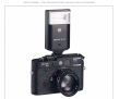
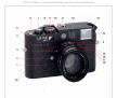
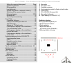
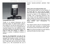
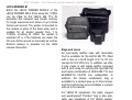
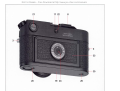
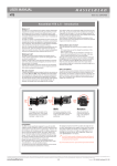
Not For Resale – Free Download at http://www.joe-chan.com/manuals
Not For Resale – Free Download at http://www.joe-chan.com/manuals
Not For Resale – Free Download at http://www.joe-chan.com/manuals
Not For Resale – Free Download at http://www.joe-chan.com/manuals
Leica Akademie
Dear Customer,
Leica not only manufactures high-performance
products for everything from observation to
reproduction: it offers a special service in the
form of the Leica Akademie. For many years,
this internationally famous facility has taught
photographic expertise in practical seminars
and training courses. It meets the needs of
keen photographers, both beginners and
advanced students, for special training in
demanding areas of 35 mm photography,
projection, and enlargement.
Congratulations on your decision to purchase
the LEICA M6 TTL. You have chosen an
excellent and unique rangefinder camera.
We wish you many years of pleasure and
successful photography with your camera.
We recommend that you read these instructions first in order to derive full benefit from the
photographic possibilities offered by your new
camera.
Up-to-date, well-equipped seminar rooms are
available at our Solms headquarters and at the
nearby "Gut Altenberg" for these courses,
which are held by experienced instructors, the
content of which ranges from general
photography to specialised fields of interest.
They provide a wealth of practical suggestions, help, and advice. Further information and
details of seminars are available from:
Leica Camera AG
Leica Akademie
Oskar Barnack Str. 11
D- 35606 Solms
Tel:
06442208421
Fax:
06442 208 425
e-mail: [email protected]
1
Not For Resale – Free Download at http://www.joe-chan.com/manuals
Contents
Page
Leica Academy .............................................................. 1
Foreword ....................................................................... 1
Nomenclature ............................................................. 2/3
Viewfinder displays ........................................................ 3
Fitting the carrying strap ................................................ 4
Power supply ............................................................. 5
Batteries..................................................................... 5
Loading and replacing the batteries ........................... 5
Automatic battery check............................................. 6
Quick-wind lever ............................................................ 7
Shutter release button.................................................... 7
Shutter speed dial .......................................................... 7
Loading the film ............................................................. 8
Opening the camera .................................................. 8
Inserting the film......................................................... 9
Closing the camera .................................................. 10
Transport to the first frame....................................... 10
Setting the film speed............................................... 10
Film rewind and removal .......................................... 11
Fitting the lens ............................................................. 12
Removing the lens ....................................................... 13
LEICA M lens design ................................................... 13
Focusing ring ........................................................... 14
Aperture ring ............................................................ 14
Depth-of-field scale .................................................. 15
Lens hoods .............................................................. 16
Use of older LEICA M lenses ....................................... 16
How to hold the camera correctly................................. 17
Bright-line viewfinder.................................................... 18
Frame selector ......................................................... 20
Rangefinder ................................................................. 22
Coincidence (double image) focusing ...................... 22
Split-image focusing................................................. 22
Exposure metering....................................................... 24
Switching on the exposure meter ............................. 24
Nomenclature
1.
2.
3.
4.
5.
6.
7.
Battery compartment cover
Lens release button
Eyelets for carrying strap
Red button for lens alignment
Lever for film rewinding release
Automatic frame counter
Shutter release button with threaded socket for
cable release
8. Quick-wind lever for film transport and shutter
wind (must be brought in stand-by position when
shooting)
9. Rangefinder window
10. Shutter speed dial with clickstops for:
• Shutter speeds from 1 to 1/1 000s
• " " for 1/50 s synchronising speed for flash
operation
• "B" for long exposures
• "OFF" for switching off the electronics
11. Accessory shoe for flash control with:
• Centre contact
• Contacts for TTL flash control
12. Bright-line frame illumination window
13. Angled rewind crank
14. Viewfinder window with mirrored strip for LED
visibility in bright light
15. Fixed ring with depth-of-field scale
16. Focusing ring
17. Aperture ring
18. Frame preselector
2
Not For Resale – Free Download at http://www.joe-chan.com/manuals
Setting the correct shutter speed/
Page
aperture combination ........................................... 25
Meter sensitivity ................................................... 26
Low light levels .................................................... 26
General information on exposure metering .......... 26
Switching off the exposure meter......................... 26
Metering diagram.............................................27/29
Metering field ....................................................... 30
Tips for exposure metering .................................. 32
Use of flash.............................................................. 38
Compatible flashguns .......................................... 39
Fitting and connecting the flash unit..................... 39
TTL flash mode.................................................... 40
Settings for TTL flash mode ................................. 40
Flash exposure displays in the viewfinder in
TTL and automatic mode ..................................... 40
Flash exposure displays in the viewfinder in
manual flash mode .............................................. 41
Flash exposure displays in the viewfinder in
strobe mode......................................................... 41
System accessories for the LEICA M6 TTL ............. 42
Interchangeable lenses........................................ 42
Filters................................................................... 42
Eyesight correction lenses ................................... 42
LEICA WINDER M............................................... 43
Bags and cases ................................................... 43
Tips on maintenance of M6 camera and lenses . .44
Alphabetical index ................................................... 45
Technical data ......................................................... 46
Other LEICA products.............................................. 48
Projectors ............................................................ 48
Binoculars............................................................ 48
LEICA Services ....................................................... 49
Information Service.............................................. 49
Customer Service ................................................ 49
LeicaCard ............................................................ 49
3
19.
20.
21.
22.
23.
24.
25.
26.
Base plate
Base plate catch
Viewfinder eyepiece
Synchronisation socket for flash units with cable
Camera back
ISO (ASA/DIN) film speed dial
Base plate holding pin
Tripod bushing A/, DIN 4503 1/4")
Viewfinder displays
LEDs-(Light Emitting Diode) for:
A Shutter/aperture balance
B Flash operation
C Bright-line frame for
50 mm and 75 mm (Example)
D Metering field for focusing
Not For Resale – Free Download at http://www.joe-chan.com/manuals
Fitting the carrying strap
4
Not For Resale – Free Download at http://www.joe-chan.com/manuals
Batteries
Silver oxide button cells
Duracell
D 357 (10 L 14)
Everready
EPX 76
Kodak
KS 76
Maxell
SR 44
National
SR 44
Panasonic
SR 44
Philips
357
Ray-o-vac
357
Sony
SR 44
Ucar
EPX 76
Varta
V 76 PX
Lithium cells
Duracell DL 1/3 N
Kodak
K 58 L
Philips
CR 1/3 N
Ucar
2 L 76
Varta
CR 1/3 N
Loading and replacing the batteries
Power supply
The LEICA M6 TTL requires two 1.5 volt silver oxide button cells or one 3 volt lithium cell
for the exposure meter and to trigger
connected flash units.
If the camera is not in use for longer periods of
time or if you wish to keep a battery with you
as replacement, lithium cells are particularly
suitable, as they can be stored for several
years with no loss of energy.
5
1. Unscrew the battery compartment cover (1).
2. Wipe any oxidation residue off the cells
using a clean cloth.
3. Insert the cells into the holder in the battery compartment cover. Pay attention to
the polarity.
4. Now screw the cover together with the cells
back into the camera.
5. To remove the batteries, follow the same
procedure in reverse.
A set of fresh batteries has a life of approximately 8 hours with the exposure meter
switched on continuously. Assuming 10second measurements in normal use, one set
of batteries therefore supplies sufficient energy
for approx. 2900 exposures, i.e. 80 films of 36
exposures each.
Not For Resale – Free Download at http://www.joe-chan.com/manuals
Automatic battery check
• In order to ensure proper battery recycling,
take the batteries to a recycling point.
• If the camera is not to be used for longer
periods, remove the batteries.
• Store batteries in a cool and dry place.
If the red LED is flickering, i.e. its brightness
fluctuates, the batteries should be replaced. If
the cells are unable to supply the minimum
operating voltage, the LED display disappears.
Note: the electrical circuit can be broken by
oxidation of the battery surfaces; this will also
cause the LEDs to go out. In this case, remove
the batteries and clean the battery terminals,
camera contacts and battery compartment
cover with a clean cloth.
Important:
• Always replace batteries in full sets. Do not
mix batteries of different make or type.
• Keep battery contacts clean.
• Do not incinerate, recharge, open, dismantle
or heat the batteries.
• Remove exhausted batteries as soon as
possible. Do not dispose of used batteries in
normal garbage as they contain environmentally harmful substances.
6
Not For Resale – Free Download at http://www.joe-chan.com/manuals
Shutter release button
The shutter release button (7) should be
pressed softly (not jerkily) until it clicks and the
shutter is opened. The shutter release has a
threaded socket to accept standard cable
releases.
Shutter speed dial
The size and location of the shutter speed dial
of the LEICA M6 TTL are ergonomically
perfect: on the one hand, the dial is extremely easy to use and can also be operated
with the camera held to the eye. On the other
hand it is well protected to prevent it from
being switched on or the settings changed
accidentally. In addition, its direction of rotation
(like that of the aperture ring on the lenses)
corresponds to the exposure meter displays in
the viewfinder: if the left-hand triangular LED is
flashing for example, turning the wheel in the
direction of the arrow, i.e. to the right, will lead
to the slower shutter speed required.
Quick-wind lever
The quick-wind lever (8) is used to advance
the film, to cock the shutter and to automatically advance the frame counter. For rapid
sequences, the user can put the lever into a
"ready position".
The shutter speed dial (10) of the LEICA M6
TTL is used to select the shutter speeds - from
1/1000s to 1s - and also the synchronising
speed " " for flash operation (1/50 s) and "B"
for long exposures.
7
Not For Resale – Free Download at http://www.joe-chan.com/manuals
When the dial is set to "B", the shutter remains
open until the shutter release button is
released.
The "OFF" position is located between "B" and
the end of the scale. When the dial is turned to
this position, the exposure meter is switched
off.
The speed selector dial engages positively at
all engraved speeds. Intermediate speeds
cannot be selected.
For details on correct exposure, see the
"Exposure metering" section on page 24.
Loading the film
Always start by making sure that there is no
film in the camera by turning the rewind crank
(13) gently in the direction of the arrow. Any
resistance indicates that a film is already
loaded; see rewinding instructions on page 11.
Begin by actuating the wind lever and pressing
the release button. Hold the camera in your left
hand with the base plate pointing upwards.
Opening the camera
1. Raise the latch (20) on the base plate (19).
2. Turn the latch to the left.
3. Remove the base plate.
4. Fold the back (23) out towards the rear.
8
Not For Resale – Free Download at http://www.joe-chan.com/manuals
Inserting the film
5. Hold the film cartridge in the right hand and
insert it about half-way into the empty
chamber.
6. Take the film leader and pull it into the takeup chamber spool (28), as shown in the
dia- gram (27) of the camera housing.
7. Using your fingers push the cartridge and
the film leader carefully into the camera.
Note: the end of the film must be tapered, as
is the case with made-up films. Under ordinary conditions it does not matter if the film
end projects through the three-post assembly. In extremely cold, dry weather, however,
the end may break off, and the drawing should
then be followed exactly.
Note: with the camera back open, three goldplated electrical contacts (29) are visible on
the back and in the camera housing. These
contacts are corrosion-free, and relatively
insensitive to dirt and dust. Special care of
these contacts is not necessary.
Important
Do not check correct loading when the
camera is open. The base plate is designed
such that it guides the film into the correct
position when attached to the camera.
When loading a new film, however, ensure
nevertheless that the contacts are kept clean
and dry.
9
Not For Resale – Free Download at http://www.joe-chan.com/manuals
arrow. The film is properly transported
when the rewind crank turns backwards
when the quick-wind lever is operated
again.
14. Finally, press the shutter release button
again and cock the shutter for the third
time. The frame counter (6) now reads 1
and the camera is ready to shoot.
Setting the film speed
Closing the camera
8. Replace the camera back.
9. Hook the base plate over the external
mounting post on the camera body (25).
10. Fold the base plate back into its normal
position, ensuring that the camera back is
in full contact so that the base plate envelops it.
11. Lock the back using the base plate catch.
The dial for setting the exposure meter to the
film speed (24) can be used to set values from
ISO 6/9° to ISO 6400/39° (ASA 6/9 DIN to
ASA 6400/39 DIN; the ISO designation is that
generally used internationally). To set the film
speed:
1. Press the centre of the dial down and turn
it until the two triangles are aligned
opposite the desired film speeds (DIN
above, ASA below).
2. When released, the disc will engage and
spring back flush with the surrounding ring
if it has been set properly.
Transport of the film to the first frame
12. Advance the film to the next frame by
means of the quick-wind lever, and release the shutter.
13. Gently pull the film taut by turning the
rewind crank (13) in the direction of the
10
Not For Resale – Free Download at http://www.joe-chan.com/manuals
The following settings are possible:
Scale
6/9°
12/12°
25/15°
50/18°
100/21°
-
Film speed
ISO (ASA/DIN)
6/9°
8/10°
10/11°
12/12°
16/13°
20/14°
25/15°
32/16°
40/17°
50/18°
64/19°
80/20°
100/21°
125/22°
160/23°
Scale
200/24°
400/27°
800/30°
1600/33°
3200/36°
6400/39°
Film speed
ISO (ASA/DIN)
200/24°
250/25°
320/26°
400/27°
500/28°
640/29°
800/30°
1000/31°
1250/32°
1600/33°
2000/34°
2500/35°
3200/36°
4000/37°
5000/38°
6400/39°
Film rewind and removal
When the last frame has been exposed, the
quick-wind lever can no longer be operated.
Before the film can be removed, it must be
wound back into the cartridge.
1. Turn rewind lever (5) to "R".
2. Swing out the lever for the rewind crank.
3. Turn the lever clockwise (in the direction of
the arrow) until the film is freed from the
take-up spool; slight resistance will be felt
at this point.
11
Not For Resale – Free Download at http://www.joe-chan.com/manuals
4. Now open the base plate.
5. Open the camera back.
6. Remove the film cartridge.
When the film is not fixed to the cartridge core,
for example when bulk film is used, it may
become separated from the core if the
advance lever is operated forcefully after the
last frame has been exposed. In this case,
proceed as follows:
1. Remove the base plate of the camera in a
completely dark room.
2. Hold the camera with the base plate open
and facing downwards.
3. Slowly operate the quick-wind lever several
times until the film protrudes far enough to
be grasped and pulled out. If necessary,
gently hit the camera against the palm of
your hand.
Fitting the lens to the camera
1. Hold the lens by the fixed ring (15).
2. Align the red lens alignment button (4) with
the lens release button (2) on the camera
body.
3. Fit the lens in this position, ensuring that it
is perpendicular to the front of the camera
4. Turn the lens slightly to the right to latch it
audibly and perceptibly into place.
12
Not For Resale – Free Download at http://www.joe-chan.com/manuals
Removing the lens
Design of the LEICA M lenses
1. Hold the lens by the fixed ring (15)
2. Depress the lens release button (2) on the
camera body
3. Turn the lens anticlockwise until the lens
alignment button (4) lines up with the lens
release button
4. Remove the lens, keeping it perpendicular
to the camera body.
The LEICA M lenses are equipped with a fixed
ring with depth-of-field scale (15), a rotatable
focusing ring (16) and an aperture setting ring
(17).
Note: When the camera is loaded with film,
change the lens in the shade of your body, as
direct sunlight may otherwise penetrate the
shutter.
13
Not For Resale – Free Download at http://www.joe-chan.com/manuals
Like the shutter speed dial, the aperture ring
engages perceptibly at each full stop (and for
most lenses also at half-stops). With a little
practice, you will also be able to set the
apertures in the dark.
Like the shutter speed dial, the aperture ring
moves in the same direction as the exposure
meter displays in the viewfinder:
When the left triangular LED comes on, for
example, turning the dial in the direction of the
arrow, i.e. to the right, causes the slower
shutter speed required to be set.
Focusing ring
The focusing ring (16) shows the distance set
and, in conjunction with the scale (15), the
depth-of-field range. For details on focusing,
see the "Rangefinder" section on page 22.
For further details on setting the correct
exposure, see the "Exposure metering" section
on page 24.
Aperture ring (17)
The aperture values are standardised worldwide. They are selected such that the amount
of light reaching the film is always halved when
the lens is stopped down between two
successive apertures (stops). One stop
corresponds to one value on the shutter speed
dial (10).
14
Not For Resale – Free Download at http://www.joe-chan.com/manuals
indicates the range of sharpness at the set
focus distance.
For example, using the LEICA SUMMILUX-M
f/1.4/50 mm lens focused at 5 metres, the
depth-of-field at f/4 ranges from approximately
4 to 8 metres. Stopping down to f/11 at the
same focusing distance, however, increases
the range to 3 - 20 metres.
Depth-of-field scale
The plane which is rendered sharpest is the
plane, parallel to the film, upon which the lens
is focused. The optimum sharpness decreases
progressively in front of and behind this plane
such that a certain range exists within which
the image is, to the eye, rendered sharply.
This range is termed the depth of field. It is
dependent on the focus setting, the focal
length of the lens (the two values together
determine the reproduction scale) and the
aperture. Stopping down, i.e. selection of a
larger f-number, increases depth-of-field,
whilst widening the aperture, i.e. selection of a
smaller f-number, decreases it. The depth-offield scale in conjunction with the focusing ring
15
Not For Resale – Free Download at http://www.joe-chan.com/manuals
Use of older LEICA M lenses
All LEICA M lenses can be used without
restriction. However, the exposure metering
system does not function with the following
types:
HOLOGON f/8/15mm,
SUPER-ANGULON-M f/4/21 mm,
SUPER-ANGULON Mf/3.4/21 mm,
ELMARIT-M f/2.8/28 mm
up to Serial No. 231 4921.
Lens hoods
Each LEICA M lens is supplied with a lens
hood the design of which is geared to the lens.
Several lenses have built-in telescopic lens
hoods. The lens hoods should always be used
as they provide both shade from stray light and
glare and protection against rain drops or
fingerprints.
The following lens must be set to infinity during
fitting/removal:
SUMMICRON with close focusing f/2/50 mm
16
Not For Resale – Free Download at http://www.joe-chan.com/manuals
How to hold the camera correctly
In order to achieve sharp, well-focused photographs, the camera must be held as steadily and comfortably as possible. Hold the
LEICA M6 TTL in a suitable, safe "three-point
holding position" as follows: hold the camera
with your right hand with your index finger on
the release button and your thumb pushed
behind the quick-wind lever in its operating,
standby position. In addition, support the lens
from below with your left hand, with which you
can refocus quickly at any time, and press the
camera against your forehead.
For vertical pictures, turn the LEICA M6 TTL to
the left and keep your hands in the same
position as for horizontal shots. You can
however also rotate the camera to the right. In
this case, it may be advantageous to release
the shutter using your thumb.
Note: We recommend the practical handgrip M
(accessory) to enable you to hold the LEICA
M6 TTL and to carry it securely whilst keeping
your hands free (order No. 14 405).
17
Not For Resale – Free Download at http://www.joe-chan.com/manuals
Bright-line viewfinder
The bright-line viewfinder of the LEICA M6
TTL comprises not only a high-quality, large,
bright and high-contrast viewfinder showing
every detail which will appear on the final
picture, but also a highly accurate lens-coupled rangefinder.
The size of the frame corresponds to an image
field of 23 x 35 mm (slide format) at the closest
focusing distance for each lens. At longer
distances, the image will contain a somewhat
larger subject field than that shown within the
bright-line frame.
The frames are coupled to the focusing
mechanism such that parallax errors (the
distance between lens and viewfinder axes)
are automatically compensated for as the lens
is focused, and the bright-line frame is the
same as the film image in the entire range
from 0.7 m to ∞.
There are two LEICA M6 TTL models with
different versions of this viewfinder, which
differ in their magnification:
responding bright-line frame is automatically
reflected into the viewfinder in the combinations 28 + 90 mm, 35 + 135 mm, and 50 + 75
mm.
When the LEICA M6 TTL is used with 0.85x
viewfinder magnification, a corresponding five
frames are reflected into the viewfinder for the
focal lengths from 35 mm upwards.
The centre of the viewfinder contains a
somewhat brighter rectangle: this is the LEICA
rangefinder. All lenses with focal lengths from
21 to 135 mm couple to the rangefinder when
attached to the LEICA M6 TTL.
With the exposure meter switched on, the
lower edge of the viewfinder also displays the
LEDs of the exposure meter or the LED flash
symbol.
For details on distance and exposure metering and flash operation, refer to the corresponding section on pages 22, 24 and 38.
When lenses with focal lengths of 28 (from
serial No. 2411001 onwards), 35, 50, 75, 90
and 135 mm are used on the LEICA M6 TTL
with 0.72x viewfinder magnification, the cor18
Not For Resale – Free Download at http://www.joe-chan.com/manuals
LED for flash operation
Bright-line
frame
35 mm
Bright-line
frame
135 mm
LED’s for shutter/aperture balance
Metering field
for focusing
19
Not For Resale – Free Download at http://www.joe-chan.com/manuals
Frame preselector
The frame preselector lever (18) extends the
possibilities of the LEICA M6 TTL viewfinder.
Using this integrated universal viewfinder, you
can view frames which do not correspond to
the lens which is actually fitted. Thus, you can
test whether the composition would be better
served by a different focal length.
When the lever is pointing outwards, i.e. away
from the lens, the frames for the 35 and 135
mm focal lengths are displayed.
When the lever is in its vertical, central position, the frames for the 50 and 75 mm focal
lengths are shown.
When the lever is pointing inwards, i.e.
towards the lens, the LEICA M6 TTL viewfinder with 0.72x magnification displays the
frames for the 28 and 90 mm focal lengths,
and the 0.85x magnification viewfinder only
shows the bright-line frame for the 90 mm
focal length.
20
Not For Resale – Free Download at http://www.joe-chan.com/manuals
*not for LEICA M6 TTL 0.85
21
Not For Resale – Free Download at http://www.joe-chan.com/manuals
Rangefinder
Coincidence (double image) focusing
Thanks to its high effective base line value, the
rangefinder of the two LEICA M6 TTL models
permits very precise control. This is particularly
advantageous when wide-angle lenses, which
provide a relatively large depth-of-field, are
used. The larger magnification of the 0.85-fold
viewfinder with its longer base line leads to
even higher accuracy:
In most cases, and particularly for pictures of
people, the coincidence or double-image
method is preferable because it requires no
straight lines in the subject. Simply cover the
most important part of the subject with the
rangefinder field, turn the focusing ring of the
lens until the double image merges to one, and
recompose (if necessary) to make the
exposure.
Mechanical base line x Viewfinder
(distance between
magnification
the optical axes of
the viewfinder
and the rangefinder
window
= Effective
base line
Split-image focusing
LEICA M6 TTL
with 0.72x
viewfinder
69.25 mm
x 0.72
Approx.
= 49.9 mm
LEICA M6 TTL
with 0.85x
viewfinder
69.25 mm
x 0.85
Approx.
= 58.9 mm
The rangefinder field is the bright rectangle in
the centre of the viewfinder field. If you cover
up the large viewfinder window (14), only the
bright-line frames and the rangefinder field
remain visible. The bright, sharply defined
rangefinder field permits the use of either
coincidence or split-image rangefinder focusing.
For pictures of buildings or other subjects
containing straight vertical lines, position the
rangefinder field such that it is intersected by a
line. Now turn the focusing ring of the lens until
one continuous line is formed.
In practical use, it may be advantageous to
combine both methods.
22
Not For Resale – Free Download at http://www.joe-chan.com/manuals
Double image = out of focus
Broken line = out of focus
Coincident image = in focus
Continuous line = in focus
23
Not For Resale – Free Download at http://www.joe-chan.com/manuals
The unevenness of the white is not a result of
poor manufacturing tolerances, but is due to
the fact that a thick, complete coating cannot
be applied to the rubberised cloth shutter
curtain without the shutter performance being
impaired. The irregular structure of the
metering spot in no way affects the meter
reading.
Exposure metering
The LEICA M6 TTL meters for exposure under
ambient light through the lens at the working
aperture. The reading is selective, by light
reflected from a bright metering field onto a
photo diode (arrow). This diode is located
behind a collecting lens to the left of and
above the shutter. The metering field
(diameter: 12 mm, i.e. approx. 13% of the
negatives size) is situated in the centre of the
first shutter curtain.
The lens f-stop and shutter speed for correct
exposure are indicated by the appearance of
the light balance (
) in the viewfinder: the
exposure is correct when only the round LED
in the middle comes on.
Switching on the exposure meter
The exposure meter is switched on by light
pressure on the shutter release button (7),
providing that the shutter is cocked and the
shutter speed dial is not set to "B" or "OFF".
When one of the two triangular LEDs or the
central round LED comes on, the exposure
meter is ready for operation.
24
Not For Resale – Free Download at http://www.joe-chan.com/manuals
If finger pressure is released without the
shutter being depressed, the exposure meter
remains switched on for approx. 14 s and the
corresponding LED(s) remain on.
When the shutter is activated, the meter
switches off and the LEDs in the viewfinder go
out.
When the shutter is not cocked, or the shutter
speed dial is set to "B" or "OFF", the exposure
meter remains switched off.
Then:
1. Switch on the exposure meter
2. Turn the shutter speed dial and/or the
aperture ring on the lens in the direction
indicated by the flashing LED until only the
round LED comes on.
In addition to the direction of rotation of both
shutter speed dial and lens aperture ring
required for correct exposure, the three LEDs
of the light balance also indicate over-, underand correct exposure as follows:
Note: at very low levels of luminance, i.e. at
the threshold of the light metering range, the
LEDs may take approx. 0.5 s to come on.
Underexposure by at least one f-stop;
turn lens aperture ring clockwise.
Underexposure by half an f/stop;
turn lens aperture ring clockwise.
Correct exposure
If the luminance levels fall below the working
range of the exposure meter, the left-hand
triangular LED flashes.
Overexposure by half an f/stop;
turn lens aperture ring anticlockwise.
Overexposure by at least one stop;
turn lens aperture ring anticlockwise.
Setting shutter speed/lens aperture combinations for correct exposure
For correct exposure metering, the shutter
must be cocked and the shutter speed dial
must be set at a marked speed.
25
Not For Resale – Free Download at http://www.joe-chan.com/manuals
Meter sensitivity
2
The light metering range begins at 0.03 cd/m .
The working range at ISO 100/21° extends
from -2 to 20 EV (exposure value), i.e. from 4 s
(shutter speed dial position "B") at f/1 to
1/1000s at f/32 (see also diagram on page 29).
Very low light levels
Should the light level fall below the range of
the exposure meter, the left triangular LED
flashes.
Since the meter uses the working aperture, the
LEDs may also flash when the lens is stopped
down.
The exposure meter remains on for approximately 12 seconds after finger pressure is
removed from the shutter release button, even
if the light level is below the threshold
sensitivity level. If the light level improves
during this time (e.g. if the composition is
changed or the aperture opened), the LEDs
stop flashing and come on permanently.
General information on exposure
metering
Most scenes contain an even distribution of
bright and dark subject details and reflect an
average of 18% of the light falling on them.
This value of 18% corresponds to an average
grey tone to which exposure meters are
calibrated. Very bright subjects, such as snowladen winter scenes, sandy beaches, whitewashed walls or a white wedding gown, reflect
more light toward the exposure meter, tending
to result in underexposure.
Predominantly dark subjects such as a black
steam locomotive, dark grey slate roofs, and
navy-blue uniforms reflect much less light, and
meters tend to overexpose. To achieve correct
exposures in these cases, the measured
values must be corrected, unless exposure is
measured selectively by inclusion of only a
portion containing a representative sampling of
dark and light subject details. You would for
example meter on the bride's face and not on
her white gown. A landscape shot with a wideangle lens should be metered with the LEICA
M6 TTL pointing downward to exclude the
bright sky.
When no such metering alternative is available, a compensation factor of 2x or 4x can be
26
Not For Resale – Free Download at http://www.joe-chan.com/manuals
used, the lens aperture can be opened by one
or two f-stops, or the shutter speed increased.
White snow under a clear sky with bright
sunlight often calls for an exposure increase of
4x, i.e. instead of the specified shutter speed
of 1/1000 s and f/8, use 1/250 s and f/8 or
1/1000 s and f/4. When photographing less
bright subjects such as a sandy beach, a
compensation factor of 2 is sufficient.
The reverse is the case for dark subjects. Note
the tips below on exposure metering.
Switching off the exposure meter
If the camera is stored in a bag or left unused
for some time, the shutter speed dial should be
set to "OFF". The exposure meter is then
switched off.
Metering diagram
Data on the metering range of the exposure
meter can be found on the right-hand side of
the diagram.
Data on the working range of the focal-plane
shutter and lenses can be seen on the left.
The exposure values (EV) are shown in the
middle.
The metering range of the exposure meter is
indicated on the right-hand side of the
diagram, in cd/m2 (candela per square metre).
The ISO film speed values (Sv) are shown at
the top of the diagram.
The different exposure times in seconds
(Tv=Time value) are shown on the left-hand
side of the diagram.
27
Not For Resale – Free Download at http://www.joe-chan.com/manuals
The working range of the LEICA M6 TTL
shutter is indicated schematically by the hatched vertical column at the far left-hand side of
the drawing, "B" representing the unrestricted
upper end.
The aperture values (Av) are shown on the
lower left-hand side.
Example A shows the correlation between the
film speed, luminance (brightness), exposure
and aperture.
First follow the vertical line from the film speed
(ISO 100/21°) down to the intersection on the
horizontal line representing the corresponding
luminance. In example A, this is 4000 cd/m2,
i.e. a typical value for bright sunlight. The line
now runs diagonally to the vertical line
indicating the aperture (11), and from there
horizontally to the required exposure (1/250 s).
In the course of this diagonal, the exposure
value (15) can also be read off.
Example B shows that in candlelight and with
a film speed of ISO 400/27° (1 cd/m2),
photographs should be taken with an aperture of f/1.4 and a shutter speed of 1/15s. An
aperture of f/11, for example, can no longer be
used as the corresponding shutter speed of 4
s is not available on the shutter speed dial. As
the slowest shutter speed available on the dial
is only 1 s, exact metering is also no longer
possible. The correct shutter speed can
therefore be obtained only by conversion or
from this diagram.
28
Not For Resale – Free Download at http://www.joe-chan.com/manuals
Metering diagram
29
LEICA M6 TTL
Viewfinder magnification 0.72
Not For Resale – Free Download at http://www.joe-chan.com/manuals
Metering fields
The metering field covers approx.
23% of the viewfinder image for the
lens being used.
LEICA M6 TTL
Viewfinder magnification 0.85
However, the following reference
value applies to all lens focal lengths:
The diameter of the circular metering
field is approx. 2/3 of the short side of
the applic-able bright-line frame. This
also applies to lenses with viewfinder
attachments, such as the LEICA
ELMARIT-M f/2.8/135mm.
30
24
mm
21
mm
24
mm
21
mm
Not For Resale – Free Download at http://www.joe-chan.com/manuals
90
mm
135
mm
75
mm
28
mm
35
mm
50
mm
90
mm
135
mm
75
mm
28
mm
35
mm
50
mm
31
Not For Resale – Free Download at http://www.joe-chan.com/manuals
Tips for exposure metering
Landscapes, close-ups or portraits, in the
living room, at the airport or at parties - the
majority of subjects contain many bright and
dark details. Therefore, in general, exposure
metering is not a problem. When the camera is
tilted a little or turned to the left or right, the
exposure value remains unchan- ged with
selective metering. However, if a landscape
scene containing many white clouds is
photographed using a wide-angle lens or if the
exposure meter is influenced by very bright
lamps in a Bavarian beer tent, for example, the
camera should be turned towards an area
containing no particular bright or dark details.
To meter the exposure in the beer tent, the
lens was pointed slightly downwards and to
the left towards the lower left-hand corner of
the picture to prevent the light source directly
above the head of the person forming the
subject from influencing the exposure reading.
In most cases, the photographer looks through
the viewfinder whilst moving the camera in
order to find the right framing - even for
snapshots. The photographer can determine at
the same time whether there is a sufficiently
even distribution of dark and light details.
32
Not For Resale – Free Download at http://www.joe-chan.com/manuals
33
Not For Resale – Free Download at http://www.joe-chan.com/manuals
A easily identified detail in the frame is also
necessary for focusing. If this detail does not
happen to be in the centre of an interesting
picture area, the camera again has to be
moved; the dark/light distribution can of course
be checked at the same time. The two pictures
above were taken in this way.
Left: focusing and exposure metering on the
boy on the right in the left-hand window - the
camera is returned to the desired picture area
- considerable change in exposure value, as
the exposure meter now covers predominantly
white details - move the camera therefore to
the left and point the lens down for renewed
exposure metering (metering field of the
exposure meter is partially outside the subject
area) - return to the original subject area shoot.
34
Not For Resale – Free Download at http://www.joe-chan.com/manuals
On the bright beach of Acapulco the exposure value was determined by moving the
camera to the right and metering outside the
range of the subject area. The area which was
metered contained reed huts, palm trees,
deckchairs and people, i.e. an even
distribution of light and dark details.
Opening the aperture by two stops corrects the
exposure value for purely white details, as
does multiplying the shutter speed by 4 (e.g.
1/125 s instead of 1/500 s). For light-coloured
details such as sand, it is sufficient to open the
aperture by one stop or double the shutter
speed.
If such substitute measurements are not
possible, exposure metering should be carried out on the light details, for example, the
light sand on the beach or in the desert, the
whitewashed walls in a Greek village or the
snow on the run of a ski slope, and the value
then corrected accordingly.
In sunny snowscapes the correct exposure for
the areas of sunlight can be determined by
metering in the shade. In this case no correction need be made.
For photographs of spotlit subjects, when
many details of the subject are in the shadow,
or for predominantly dark subjects such as
steam engines or black fields of lava, small
portions of the picture area with a good dis35
Not For Resale – Free Download at http://www.joe-chan.com/manuals
tribution of light and dark details can usually be
found which can be metered using spot
metering.
In this picture taken at the ballet, the metered
area was at the far right, partly outside the
picture area. If suitable areas are not available, the dark details must be metered and a
correction made, resulting in a smaller aperture or faster shutter speed. Stopping down by
half a stop (in extreme cases a whole stop) is
sufficient.
If there is considerable contrast between light
and dark parts of the image, the exposure
latitude of the films ceases to be sufficient to
register the full tonal range of the subject in
both the "light" and the "shade". The photographer must decide where he wishes to retain
the greatest detail. For example, a person can
appear as a black silhouette (under-exposed)
in front of a correctly exposed landscape, or
correctly exposed in front of a "burnt-out"
background (overexposed). A reading from
"light" and "shadow" and the resulting average
exposure usually leads to unsatisfactory
results because delicate differences in
brightness are lost in both the light and the
dark areas.
36
Not For Resale – Free Download at http://www.joe-chan.com/manuals
The landscape shot was taken following
metering in the lower right-hand part of the
picture (shadow of the tree on the grass and
the horse). For fast-moving subjects, there is
often no time for exposure metering. In such
cases, exposure metering is performed in
advance. In this example, the top left-hand
corner was metered, as the tape bordering the
racetrack provided light and dark details.
Deliberate over- or underexposure often
enhances the character of a picture and can
be used as a good compositional aid. In this
landscape shot, the fir trees and mountain ridges on the left of the picture (without the sky)
were metered for the exposure, and the value
was then reduced by two stops.
37
Not For Resale – Free Download at http://www.joe-chan.com/manuals
Use of flash
In addition to the photocell for ambient light,
the LEICA M6 TTL is equipped with a second
photocell for flash (arrow). This silicon
photocell, located on the right below the
shutter, enables the camera to measure the
light emitted by the flash through the lens, at
the working aperture. Through-the-lens
metering on the LEICA M6 TTL is centre
weighted and integral.
flash was specially designed for the LEICA M6
TTL.
Important
In order to trigger and control the flash units
connected by means of the accessory shoe or
the coaxial contact (x), the LEICA M6 TTL
must be loaded with batteries and the exposure meter must be switched on by lightly
pressing the shutter release button.
The camera can only control the flash light
itself if flash units are used which are compatible with SCA 3000 and have an SCA 3501
adapter, or if the LEICA SF20 flash unit (order
No. 14414) is mounted on the camera. This
38
Not For Resale – Free Download at http://www.joe-chan.com/manuals
modern thyristor-controlled electronic flash
units.
Compatible flash units
Thanks to its compact dimensions and its
dedicated design, the LEICA SF20 is particularly suitable for use with the LEICA M6 TTL. It
is very simple to use, as it is equipped with an
integrated adapter foot with additional control
and signal contacts for automatic transfer of a
range of data and settings. In addition, it
features a number of additional functions of
interest.
Fitting and connecting the flash unit
When mounting a flash unit on the hotshoe of
the LEICA M6 TTL, ensure that the adapter
foot of the flash unit is fully inserted and firmly
secured by means of the tightening nut, if
available. This is especially important in the
case of flash units with additional control and
signal contacts, as movements of the flash unit
within the adapter foot may lead to the contact
being
broken
and
consequently
to
malfunctions.
The coaxial contact (x,22) for connecting flash
units with cable connection is located below
the accessory shoe at the back of the camera.
Note: the camera and flash unit must both be
switched off before the flash is fitted.
However, the photographer can also fit any
other proprietary flash unit, provided they are
equipped with standard sockets, and also oncamera flash units with standardised adapter
foot. These flash units are fired via the centre
contact (x,11). We recommend the use of
39
Not For Resale – Free Download at http://www.joe-chan.com/manuals
TTL flash mode
This mode is available with the LEICA SF20
and any other SCA 3000 flash unit equipped
with the SCA adapter 3501. As soon as the
requisite quantity of light has been emitted, the
camera electronics of the LEICA M6 TTL
transmit a "stop" signal to the flash unit, which
immediately interrupts light output. This flash
mode offers the advantage that all factors
influencing exposure of the film (e.g. filters and
aperture changes) are automatically taken into
account.
In addition, the LEICA M6 TTL transfers the
film speed set on the camera to the flash unit.
2. Set the desired aperture or that required for
the subject-to-camera distance.
3. Prior to any flash exposure, switch on the
exposure meter by lightly pressing the
shutter release button. If the release button
is pressed down completely and the
exposure meter remains switched off, the
flash unit may not be fired.
Note: since the aperture selected on the
LEICA M6 TTL is not transferred to the flash, it
must be set manually on the flash unit to
enable the range to be read off on the latter, if
the flash has such a display.
Flash units equipped with the corresponding
displays can thus automatically adjust their
range settings. The film speed setting cannot
be influenced by means of the flash unit.
Settings for the TTL flash mode
After switching on the flash unit and setting it
to "TTL", proceed as follows:
1. Turn the shutter speed dial of the LEICA M6
TTL to the flash synchronising speed " "
(1/50 s) or select a slower shutter speed (or
"B") for special effects.
40
Not For Resale – Free Download at http://www.joe-chan.com/manuals
Flash exposure displays in the viewfinder
in TTL and automatic flash mode with the
flash unit SF20 or flash units equipped with
the SCA 3501 adapter
In the viewfinder of the LEICA M6 TTL, an
LED in the shape of a flash (3) indicates the
different modes:
•
•
•
•
•
•
is not displayed even though the flash is
switched on:
The shutter speed set on the camera is
faster than 1/50 s
flashes slowly (at 2 Hz) before the shutter
is released:
The flash unit is not yet operational.
flashes before the exposure
The flash is operational.
continues to flash after the exposure:
Flash exposure was correct, flash remains
operational.
flashes rapidly after the exposure (at
4 Hz)
Flash exposure was correct, but flash is
recycling.
does not flash following the exposure:
Underexposure, for example due to an
aperture too small for the subject
Flash exposure displays in the viewfinder
in manual flash mode
•
is not displayed even though the flash is
switched on:
The shutter speed set on the camera is
faster than 1/50 s
•
flashes slowly (at 2 Hz) before the shutter
is released:
The flash unit is not yet operational.
•
flashes before the exposure
The flash is operational.
Flash exposure displays in the viewfinder
in stroboscope flash mode
•
is not displayed even though the flash is
switched on:
The shutter speed set on the camera is too
fast for the number of flashes set on the
flash unit
•
flashes slowly (at 2 Hz) before the shutter
is released:
The flash unit is not yet operational.
•
flashes before the exposure:
The flash is operational.
Note: for details on flash operation, particularly with other, non-TTL-compatible flash
units, and information on the different modes
of the flash units, refer to the instruction sheet
of your flash unit.
41
Not For Resale – Free Download at http://www.joe-chan.com/manuals
System
M6TTL
accessories
for
the
LEICA
Interchangeable lenses
The LEICA M system is ideal for fast and
candid photography. The range of lenses
comprises focal lengths from 21 to 135 mm
and widest apertures of f/1.
Filters
In black and white photography, filters are
used for controlled rendition of tonal values, for
example in order to achieve a natural
reproduction of different colours in grey tones,
or in order to improve the appearance of the
sky or clouds on the picture. In colour
photography, filters can be used to adjust
colour rendition to the wishes of the user or to
the spectral sensitivity of the film employed.
the individual spectral ranges; consequently
denser, more extreme filters may cause
deviations from the correct exposure. For
example, orange filters generally require one
stop more exposure; red on average two stops
more. A universally valid correction factor is
not possible as the red sensitivity of black and
white films varies considerably.
Eyesight correction lenses
For optimal matching of the viewfinder to the
eye, correction lenses in the following
strengths are available (dioptres, spherical):
0.5/1.5/2/3.
A range of different filters, equipped with
standard filter thread sizes, are available for
the current LEICA M lenses, including a universal polarising filter.
When the exposure is metered through the
lens, any reduction in the quantity of light by
the filter is automatically taken into account.
However, films have different sensitivities in
42
Not For Resale – Free Download at http://www.joe-chan.com/manuals
LEICA WINDER M
Either the LEICA WINDER M/M4-P or the
LEICA WINDER M4-2 (from serial No. 10350)
can be fitted to the LEICA M6 TTL for
automatic film transport and shutter cocking,
for single exposures and series of up to three
frames per second. The winder is mounted on
the camera in place of the base plate, and is
suitable for all shutter speeds from 1 to
1/1000s, including B. When the winder is
switched off or if the batteries are dead, the
film can still be wound on manually as normal.
Remote release is possible via the cable
release connection.
Bags and cases
An ever-ready leather case with removable
front is available for the LEICA M6 TTL fitted
with a lens of a focal length of 21 to 50 mm
(except for M f/1/50 mm). In addition, we offer
a bag made of soft nappa leather equipped
with a wrist strap for carrying the specially flat
and handy combination of LEICA M6 TTL and
ELMARIT-M f/2.8/50 mm (collapsible). In
addition, the classic combination bag is
available for a camera plus up to three lenses,
and the hold-all bag accommodates a camera
with up to five lenses.
For LEICA M equipment, the small, elegant
and weatherproof "Outdoor" bag is also available (see Handbook of the LEICA system,
pages 4-4 and 4-6).
43
Not For Resale – Free Download at http://www.joe-chan.com/manuals
Tips on maintenance of your LEICA
M6 TTL and lenses
All mechanically operated bearing and sliding
surfaces on your LEICA M6 TTL have been
lubricated. Please remember this when the
camera is not in use for longer periods of time.
To prevent the grease from becoming tacky,
the camera shutter should be cocked and
released several times at each shutter speed.
Do this around every three months without film
loaded. We also recommend that you operate
all the other controls (e.g. frame preselector
lever and film speed dial). The lens helix and
the aperture setting rings should also be
moved from time to time.
A lens acts as a burning glass when bright
sunlight shines on the front of the camera. The
camera should therefore never be put down
without first being protected against strong
sunlight. Damage to the camera shutter can be
prevented by using the lens cover and keeping
the camera in the shade or in a case.
To remove stains and finger marks, wipe the
camera and lens with a clean, lint-free cloth.
Rougher dirt in less accessible corners of the
camera body can be removed with a small
brush. Do not use liquid cleaning agents to
clean the camera body. Dust and lint in the
interior of the camera (e.g. on the film guide)
can best be cleaned using a dry soft-haired
brush which has been degreased several
times in ether.
Normally a soft-haired brush is sufficient for
the removal of dust from the outer lens elements. In case of more stubborn dirt, a very
clean, soft cloth completely free of foreign
matter can be used. Wipe carefully with a
circular movement from the inside outwards.
We recommend micro optic cloth (available
from your photo dealer or optician) stored in a
protective container and washable at temperatures up to 40° (without fabric softener,
never iron).
Never use special cleaning cloths for glasses
which are impregnated with chemicals, as they
can damage the lens elements.
Optimal front lens protection in unfavourable
conditions (for example sand, salt water spray)
can be achieved with colourless UVa filters.
These can, however, as with any filter, cause
undesirable reflections in certain backlight
situations and with high contrast. We
recommend the use of a lens hood since it
also protects the lens from finger prints and
rain.
44
Not For Resale – Free Download at http://www.joe-chan.com/manuals
Note the serial numbers of your camera
(engraved on the accessory shoe of your
LEICA M6 TTL) and lenses since these are
extremely important in the event of loss.
Alphabetical index
Aperture setting ring
Bags and cases
Battery
Bright-line viewfinder
Carrying strap
Customer service
Depth-of-field scale
Exposure meter
- General information on exposure
metering
- Switching on
- Sensitivity
- Switching off
- Tips
- Very low light levels
Eyesight correction lenses
Film
- Loading
- Film speed
- Rewinding and removing
Filters
Flash operation
Flash synchronisation
Page
14
43
5
18
4
49
15
24
26
24
26
27
32
26
42
8
9
10
11
42
38
39
Focusing ring
Frame preselector lever
Handgrip M
Holding the camera
Interchangeable lenses
Lens hoods
M lenses
- Design
- Use of older lenses
Metering diagram
Metering fields
Quick-wind lever
Rangefinder
Shutter/aperture combination
Shutter release button
Shutter speed dial
Technical data
Tips on maintenance of camera and
lenses
TTL flash mode
Winder M
45
22
20
17
17
42
16
12
13
16
27/29
30
7
22
25
7
7
46
44
38
43
Not For Resale – Free Download at http://www.joe-chan.com/manuals
Technical data
Camera type: 35 mm rangefinder camera for the 24 x 36 mm
format; mechanical shutter and selective through-the-lens
exposure metering of the ambient light, or centre-weighted
integral metering of the flash light with compatible flash units
Lens mount: LEICA M bayonet
Lenses: 14 LEICA M lenses with focal lengths from 21 to
135 mm
Bright-line viewfinder: The subject is not viewed through
the camera lens
Viewfinder magnification: 0.72 x (or 0.85 x) for all lenses
Viewfinder eyepiece: Adjusted for -0.5 dioptres, provision
for screw-in correction lenses
Viewfinder display: Six (five in the 0.85x viewfinder) brightline frames for the various focal lengths; rangefinding field; 3
LEDs for shutter/aperture balance, 1 LED for flash operation
Framing: By projection of pairs of bright-line frames into
viewfinder: 28 and 90 mm (single 90 mm frame in the 0.85 x
viewfinder), or 35 and 135 mm, or 50 and 75 mm; automatic
selection of correct frame for lens in use
Frame preselector: A three-position lever adjacent to the
lens bayonet permits projection of two pairs of bright-line frames (single 90 mm frame in 0.85 viewfinder) without the lens
needing to be changed
Parallax compensation: Automatic compensation of horizontal and vertical viewfinder/lens parallax, coupled to focusing drive; the bright-line viewfinder frame automatically frames the subject to match the image in the lens
Identical image in viewfinder and on film: The bright-line
frame corresponds to a framed 35 x 23 mm close-up slide for
each focal length. At infinity, the film frame covers slightly
more than the bright-line frame.
Wide-base rangefinder: Bright-field split-image and doubleimage rangefinder in centre of viewfinder image.
Effective base line: 49.9 mm (in the 0.72x viewfinder;
mechanical base line 69.25 mm x 0.72 x viewfinder magnification), or 58.9 mm (in 0.85x viewfinder; mechanical base
line 69.25 mm x 0.85x viewfinder magnification)
Partly silvered viewfinder window: To improve visibility of
the LEDs against a bright subject background, the lower and
upper edge of the viewfinder window is silvered.
Exposure metering method: Selective through-the-lens
metering at working aperture; centre-weighted integral TTL
metering of the flash light at working aperture when compatible flash units are used.
Exposure metering principle: Measurement of light reflected by 12 mm diameter white circular dot in centre of first
shutter curtain; area approx. 13% of negative size.
Orientation of exposure metering field in the viewfinder:
Field diameter about 2/3 length of shorter side of viewfinder
frame.
Photocell: Silicon photodiode behind condenser lens top left
(for ambient light) and bottom right behind bayonet fitting of
camera.
Spectral range: Modified by filters in front of photocell to
match typical spectral range of human eye.
Sensitivity of exposure range: 0.03 cd/m2 to 125 000
cd/m2 at f/1
Low-light warning: By means of flashing triangular LED on
the left in the viewfinder.
Working range: At ISO 100/21°, exposure values from -2 to
20 EV, i.e. 4 s at f/1 ("B" setting) to 1/1000 s at f/32.
Switching on the exposure meter: By light pressure on
shutter release when shutter is cocked. Following the exposure, or with the shutter speed set to "B" or "OFF", the exposure meter is switched off after approx. 12 s.
Exposure meter display: By light balance in the viewfinder
with three red LEDs; the two triangular LEDs indicate the
direction of rotation of aperture ring and shutter speed dial
required for the shutter/aperture balance; in the event of
under- or overexposure of at least 1 EV, one of the two triangular LEDs flashes; in the event of under- or overexposure of
up to approx. 1/2 EV, one of the two triangular LEDs as wells
as the round LED in the centre flash; when shutter and aperture match the exposure meter, i.e. when selected exposure
is correct, only the round LED in the centre comes on.
46
Not For Resale – Free Download at http://www.joe-chan.com/manuals
Aperture settings: By ring on front of lens, clickstops at full
and half-stop settings.
Shutter settings: Large, easily accessible shutter speed dial
on top plate of camera; also serves as main switch. Clickstop settings, can be read from above: OFF, B, 1 to 1/1 000s
and F (=1/50 s, flash sync speed, i.e. fastest shutter speed
for flash operation); intermediate settings not possible.
Setting the correct shutter/aperture combination: Switch
on exposure meter. Turn shutter speed dial and/or aperture
ring until the central round LED (for precise exposure) or the
central round LED and one of the triangular LEDs (for exposure with ± 2EV) in the viewfinder come on; only one of the
triangular LEDs flashing indicates over- or underexposure
together with the required direction of rotation of the aperture ring and shutter speed dial.
Film speed: ISO 6/9° to ISO 6400/39°; ISO 12/12° to ISO
3200/36° for TTL mode
Power supply to exposure meter: Two silver oxide button
cells, IEC type SR44 (diameter 11.6 mm, height 5.4 mm) or
one 1/3 N lithium battery (diameter 11.6, height 10.8 mm).
Automatic battery check: If battery voltage is inadequate
for accurate exposure metering, the right LED flashes.
Battery life: At an ambient temperature of 20°C and with the
camera continuously switched on (shutter release button
pressed), one set of fresh batteries lasts approx. 8 hours; at
10s per reading, this suffices for approx. 2900 exposures
(approx. 80 films of 36 exposures each).
Shutter: Rubberised-cloth horizontal focal-plane shutter.
Mechanically controlled speeds from 1 s to 1/1000 s, in full
values. B for time exposures of any duration and F (=1/50 s)
for flash operation. Extremely low-noise operation.
Flash sockets: Standard accessory shoe with centre contact
and additional contacts for TTL flash control by the camera of
compatible flash units (SCA 3000 standard or with SCA 3501
adapter); standard socket (X) for flashbulbs and electronic
flash on the back of the camera; the two contacts can be
used simultaneously.
Shutter release: Shutter release button with standard thread
for cable release; gentle pressure on the button activates the
exposure meter (light balance in the viewfinder).
Film transport: Angled quick-wind lever with movable handle; 120° movement transports film and cocks shutter, interval
winding possible; "ready" position also suitable for left-eye
viewing. Motorised film transport with add-on LEICA WINDER-M.
Frame counter: With magnifying display in top plate of
camera; counts forward from -2 to 38, resets automatically on
removal of base plate.
Rewind lever: Lever for rewind release on the front of the
camera: sloped hinge-out rewind crank on the left-hand side
of the camera top plate.
Camera body: Enclosed die-cast aluminium camera, detachable base plate. Top plate: 0.8 mm die-cast zinc; frame
selector adjacent to lens mount. Eyelets on side of camera
body for carrying strap; tripod thread = A/, DIN 4503;
mechanical contact for LEICA WINDER M; LEICA M6 TTL in
black or silver chrome finish; LEICA M6 TTL 0.85 in black
chrome.
Dimensions and weight (without lens, including batteries): 138 mm (height) x 79.5 mm (width) x 38 mm (depth),
600 g.
47
Not For Resale – Free Download at http://www.joe-chan.com/manuals
Other LEICA products
Projectors
For your LEICA M6 slides, there is a comprehensive range of versatile, easy-to-use
projectors, with a large choice of options for
your LEICA M6 slides. The PRADOVIT P 2002
and the PRADOVIT P 150, PRADOVIT P 300
and PRADOVIT P 600 offer total user
convenience and a versatile range of optional
modules. Superb optical performance in
combination with traditional Leica precision
mechanics are the common denominator of all
LEICA projectors and projection lenses.
Binoculars and spotting scopes
Superb optics are the most outstanding single
feature of all TRINOVID binoculars and
TELEVID spotting scopes. They are made of
the same high-grade optical glass as the
world-famous LEICA lenses. Their excellent
optical performance, exceptional resolution
and superb brightness ensure a vivid threedimensional image even in poor light.
48
Not For Resale – Free Download at http://www.joe-chan.com/manuals
Leica Service
Internet
http://www.leica-camera.com
Information service
Should you have any technical questions
regarding the use of Leica products, please
contact the Leica information service in writing or by phone:
Leica Camera AG
Infodienst
Oskar Barnack Str. 11
D- 35606 Solms
Tel: 06442208111
Fax: 06442 208 339
e-mail: [email protected]
Customer Service
For service and repairs or in the event of
damage, please contact the Leica Camera
customer service or one of the LEICA representations abroad for assistance (see warranty card for address list). Alternatively,
consult your authorised Leica Camera dealer.
Leica Camera AG
Technischer Service
Oskar Barnack Str. 11
D- 35606 Solms
Tel: 06442208189
Fax: 06442 208 339
e-mail: [email protected]
LeicaCard
Leica Camera AG
Infodienst
Oskar Barnack Str. 11
D-35606 Solms
Tel: 06442 208 555
Fax: 06442 208 339
e-mail: [email protected]
49
Not For Resale – Free Download at http://www.joe-chan.com/manuals
Not For Resale – Free Download at http://www.joe-chan.com/manuals
® = Registered Trademark
Design subject to alterations without notice.
Leica Camera AG, Oskar-Barnack-Straße 11, D-35606 Solms/Germany
Telefon 0 64 42/2 08-0, Telefax 0 64 42/2 08-3 33
http://www.leica-camera.com [email protected]
engl. 930 689
Printed in Germany
IV/99/GX/L
Leipscher-Druck, Wetzlar
Trademark of
The Leica Camera Group