1
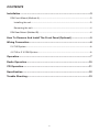
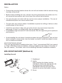
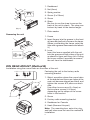
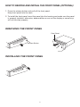
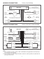
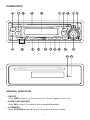
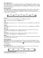
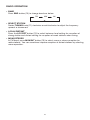
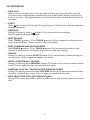
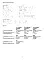
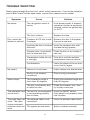
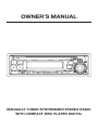
OWNER’S MANUAL
MANUALLY TUNED SYNTHESIZER STEREO RADIO
WITH COMPACT DISC PLAYER DIGITAL
CONTENTS
Installation .....................................................................................................3
DIN Front-Mount (Method A) ..................................................................................3
Installing the unit ...............................................................................................3
Removing the unit .............................................................................................4
DIN Rear-Mount (Method B) ...................................................................................4
How To Remove And Install The Front Panel (Optional) ...........................5
Wiring Connection ........................................................................................6
2 X 7W System .......................................................................................................6
4 X 7W or 2 X 25W System.....................................................................................6
Operation .......................................................................................................7
Radio Operation ..........................................................................................10
CD Operation...............................................................................................11
Specification................................................................................................12
Trouble Shooting .........................................................................................13
2
INSTALLATION
Notes:
• Choose the mounting location where the unit will not interfere with the normal driving
function of the driver.
• Before finally installing the unit, connect the wiring temporarily and make sure it is
all connected up properly and the unit and the system work properly.
• Use only the parts included with the unit to ensure proper installation. The use of
unauthorized parts can cause malfunctions.
• Consult with your nearest dealer if installation requires the drilling of holes or other
modifications of the vehicle.
• Install the unit where it does not get in the driver’s way and cannot injure the
passenger if there is a sudden stop, like an emergency stop.
• If installation angle exceeds 30˚ from horizontal, the unit might not give its optimum
performance.
30˚
• Avoid installing the unit where it would be subject to high temperature, such as from
direct sunlight, or from hot air, from the heater, or where it would be subject to dust,
dirt or excessive vibration.
DIN FRONT/REAR-MOUNT
This unit can be properly installed either from “Front” (conventional DIN Front-mount)
or “Rear” (DIN Rear-mount installation, utilizing threaded screw holes at the sides of
the unit chassis). For details, refer to the following illustrated installation methods.
DIN FRONT-MOUNT (Method A)
Installing the unit
1
2
182
53
3
1. Dashboard
2. Holder
After inserting the holder into the
dashboard, select the appropriate tab
according to the thickness of the
dashboard material and bend them
inwards to secure the holder in place.
3. Screw
(Fig. 1)
3
1. Dashboard
1
2. Nut (5mm)
6
3. Spring washer
7
4
2
4. Screw (5 x 25mm)
5
5. Screw
3
6. Strap
Be sure to use the strap to secure the
back of the unit in place. The strap can
be bent by hand to the desired angle.
(Fig. 2)
7. Plain washer
Removing the unit
1. Frame
2. Insert fingers into the groove in the front
of frame and pull out to remove the frame.
(When re-attaching the frame, point the
side with a groove downwards and attach
it.)
3. Lever
Insert the levers supplied with the unit
into the grooves at both sides of the unit
as shown in figure until they click. Pulling
the levers makes it possible to remove
the unit from the dashboard.
1
2
3
DIN REAR-MOUNT (Method B)
Installation using the screw holes on the sides of the unit.
Fastening the unit to the factory radio
mounting bracket.
1
2
4
5
3
1. Select a position where the screw holes
of the bracket and the screw holes of the
main unit become aligned (are fitted), and
tighten the screws at 2 places on each
side.
Use either truss screws (5 x 5mm) or
flush surface screws (4 x 5mm),
depending on the shape of the screw
holes in the bracket.
2. Screw
2
5
3. Factory radio mounting bracket
4. Dashboard or Console
5. Hook (Remove this part)
Note: The mounting box, outer trim ring,
and half-sleeve are not used for method B
installation.
4
HOW TO REMOVE AND INSTALL THE FRONT PANEL (OPTIONAL)
1. Press the release button and pull-off the front panel.
Keep front panel into the case.
2. To install the front panel, insert the panel into the housing and make sure the panel
is properly installed, otherwise, abnormalities occurs on the display or some keys
will not function properly.
REMOVING THE FRONT PANEL
Front Panel
Release Button
INSTALLING THE FRONT PANEL
5
WIRING CONNECTION
FOR 2 X 7W SYSTEM
CD CHANGER
CONNECTOR SOCKET
(FOR CD CHANGER VERSION ONLY)
MAIN UNIT
(GREY)
ANTENNA CONNECTOR
RCA CABLE
Rch RED
CHOKE BOX
MEMORY
BACK-UP
YELLOW
GROUND (B–)
POWER
ANTENNA
Lch
SPEAKER
Lch WHITE
BLACK
(FOR RCA LINE OUT VERSION ONLY)
FUSE
BLUE
RED
(FOR POWER ANT. VERSION ONLY)
+
–
WHITE
GREY
WHITE/BLACK
GREY/BLACK
WIRING CONNECTION
IGNITION
SWITCH (B+)
+
–
FOR 4 X 7W OR 2 X 25W SYSTEM
CD CHANGER
CONNECTOR SOCKET
(FOR CD CHANGER VERSION ONLY)
MAIN UNIT
(BROWN)
ANTENNA CONNECTOR
Rch RED
FRONT RCA CABLE
IGNITION
SWITCH (B+)
RED
MEMORY
BACK-UP
YELLOW
Lch WHITE
CHOKE BOX
GROUND (B–)
Rch
SPEAKER
(GREY)
REAR RCA CABLE
Rch RED
BLACK
Lch WHITE
BLUE
POWER
ANTENNA
2-SPEAKERS SYSTEM
WHITE
(FOR RCA LINE OUT VERSION ONLY)
4-SPEAKERS SYSTEM
FRONT
Lch SPK.
4-SPEAKERS SYSTEM
WHITE
GREY
WHITE/BLACK
GREY/BLACK
GREEN
VIOLET
GREEN/BLACK
VIOLET/BLACK
FRONT
Rch SPK.
2-SPEAKERS SYSTEM
GREY
Rch
SPK.
Lch
SPK.
REAR
GREEN/BLACK Lch SPK.
REAR
Rch SPK. VIOLET/BLACK
Note:
1. For 2-speakers system, green, violet, white/black and grey/black wire leads are
unconnected and isolated.
2. For 2-speakers system, keep the fader control at center position to maintain the
existing volume level.
6
OPERATION
4
5
17 18
16
19
3
20
6
7
14
12
8
13
9
15
10
1
11
22 21
GENERAL OPERATION
• ON/OFF
Press PWR button (1) to turn on the unit. Press it again to turn it off.
• FACEPLATE RELEASE
Press REL button (2) to detach the removable faceplate.
• LOUDNESS
Press LOU/RND button (8) shortly to reinforce the bass output.
7
2
• SET THE CLOCK
Press DSP button (9) to change the display to clock display. Press it again to return
to previous display. In clock display, press and hold the DSP button (9) for several
seconds until the clock display flashes. Press VOL (5) to change minutes or VOL
(4) to change hours.
• SELECT MODE
Press SEL button (3) to change audio mode through volume, bass, treble, balance,
and fader modes. Use VOL (4) and VOL (5) buttons to adjust the selected
mode. When mode has not been adjusted for several seconds, display returns to
normal radio or CD display.
VOL
(Volume)
BAS
(Bass)
TRE
(Treble)
Volume
Adjust volume level by using VOL (4) and VOL
Note: The unit is initially set to volume mode.
BAL
(Balance)
FAD
(Fader)
(5) buttons.
Bass
Press SEL button (3) one time. Adjust bass level by using VOL
buttons.
(4) and VOL
Treble
Press SEL button (3) two times. Adjust treble level by using VOL
(5) buttons.
(5)
(4) and VOL
Balance
Press SEL button (3) three times. Adjust sound balance between left and right
speakers by using VOL (4) and VOL (5) buttons.
Fader
Press SEL button (3) four times. Adjust sound balance between front and rear
speakers by using VOL (4) and VOL (5) buttons.
• MUTE
Press MUT button (6) to mute down sound. Press it again to release this mode and
recover previous volume level.
• SELECT MODE
Press MOD button (7) to change radio or CD mode. During CD operation, press
BND button (10) to switch to radio mode. During radio operation, when a compact
disc is inserted in the disc slot (16), press
button (14) to switch to CD mode and
start playing.
• EQUALIZATION
Press EQ button (19) to turn to equalization function and to select desired audio
mode. There are four kinds of mode as below:
FLAT
ROCK
CLASSIC
POP
• LIQUID CRYSTAL DISPLAY
The LCD (20) can show the current state of the unit.
8
EQ OFF
• FLASHING LED
If the front panel is not on the main unit, LED (21) will be flashing.
• RESET BUTTON FUNCTION
RESET button (22) is placed on the housing and must be activated with either a
ballpoint pen or thin metal object. The RESET button (22) is to be activated for the
following reasons:
- Initial installation of the unit when all wiring is completed.
- All the function buttons do not operate.
- Error symbol on the display.
Note: If press RESET button (22), the unit can’t work yet, please use a cotton swab
soaked in isopropyl alcohol to clean the socket on the back of the front panel.
9
RADIO OPERATION
• BAND
Press BND button (10) to change bands as below:
FM
MW
LW
• SELECT STATION
Rotate TUNING knob (11) clockwise or anticlockwise to adjust the frequency
upward or downward.
• LOCAL/DISTANT
Press the LOC/RPT button (12) to select between local setting for reception of
strong station and distant setting for reception of weak stations when tuning.
• MONO/STEREO
In FM band, press MON/INT button (13) to select mono or stereo reception for
radio stations. You can sometimes improve reception of distant stations by selecting
mono operation.
10
CD OPERATION
• DISC PLAY
Gently insert a compact disc with the label side facing up into the disc slot (16).
The disc is then automatically loaded into the unit and starts playing with the first
track of the disc. The digital display will indicate the track number and the time of
the track.
• EJECT
Press (eject) button (15) to stop CD play and eject CD from slot. Receiver switches
to radio operation.
• PAUSE CD
During CD playing, press
button (14) to temporarily stop playing.
Press it again to resume playback.
• SKIP TRACKS
Press TRACK button (17) or TRACK button (18) to choose the following track
or the previous track. Track numbers show on display.
• FAST FORWARD AND FAST REVERSE
Hold TRACK button (17) or TRACK button (18) for several seconds to fast
forward or fast reverse. Releasing the button to stop fast playing.
• REPEAT
During CD playing, press LOC/RPT button (12) to continuously repeat playing the
current track. Press it again to release this mode.
• INTRO: PREVIEW ALL TRACKS
During CD playing, press MON/INT button (13) to play first several seconds of each
track. Press it again to stop intro and listen to track.
• RANDOM: PLAY ALL TRACKS IN THE RANDOM ORDER
During CD playing, press and hold LOU/RND button (8) for several seconds to play
all tracks in the random order. Press it again to cancel the function.
• DISC SELECTION (FOR CDC VERSION ONLY)
During CDC mode, press CD + button or CD – button (19) to select next or previous
disc.
11
SPECIFICATION
GENERAL
Power Supply Requirements
Chassis Dimensions
Tone Controls
- Bass (at 100 Hz)
- Treble (at 10 KHz)
Maximum Output Power
- Version V
- Low Power Version
Current Drain
- Version V
- Low Power Version
: DC 12 Volts, Negative Ground
: 178 (W) x 163 (D) x 50 (H) mm
: +10 dB / –10 dB
: +10 dB / –10 dB
: 7W x 4 (ch) or 25W x 2 (ch)
: 7W x 2 (ch)
: 5 Ampere (FOR NORMAL POWER)
: 3 Ampere (FOR LOW POWER)
CD PLAYER
Signal to Noise Ratio
Channel Separation
Frequency Response
: More than 60 dB
: More than 60 dB
: 20 Hz - 20 KHz
RADIO
For 3 Bands
(Europe)
FM
87.5 to 108 MHz
10.7 MHz
5 µV
> 25 dB
For 2 Bands
(Europe)
FM
87.5 to 108 MHz
10.7 MHz
5 µV
> 25 dB
For 2 Bands
(U.S.A.)
FM
87.5 to 107.9 MHz
10.7 MHz
5 µV
> 25 dB
MW
Frequency Coverage
: 522 to 1620 KHz
IF
: 450 KHz
Sensitivity (S/N = 20 dB) : 32 dBu
MW
522 to 1620 KHz
450 KHz
32 dBu
AM
530 to 1710 KHz
450 KHz
32 dBu
Frequency Coverage
IF
Sensitivity (S/N = 30 dB)
Stereo Separation
:
:
:
:
LW
Frequency Coverage
: 150 to 280 KHz
IF
: 450 KHz
Sensitivity (S/N = 20 dB) : 35 dBu
12
TROUBLE SHOOTING
Before going through the check list, check wiring connection. If any of the problems
persist after check list has been made, consult your nearest service dealer.
Symptom
No power.
Disc cannot be
loaded or ejected.
Cause
Solution
The car ignition switch is
not on.
If the power supply is properly
connected to the car accessory
terminal, switch the ignition key
to “ACC”.
The fuse is blown.
Replace the fuse.
Presence of CD disc inside
the player.
Remove the disc in the player,
then put a new one.
Inserting the disc in reverse Insert the compact disc with
direction.
the label facing upward.
No sound.
Sound skips.
Compact disc is extremely
dirty or defective disc.
Clean the disc or try to play a
new one.
Temperature inside the car
is too high.
Cool off or until the ambient
temperature return to normal.
Condensation.
Leave the player off for an hour
or so, then try again.
Volume is in minimum.
Adjust volume to a desired level.
Wiring is not properly
connected.
Check wiring connection.
The installation angle is
more than 30 degrees.
Adjust the installation angle less
than 30 degrees.
The disc is extremely dirty
or defective disc.
Clean the compact disc, then
try to play a new one.
The operation keys The built-in microcomputer
do not work.
is not operating properly
due to noise.
Press the RESET button.
Front panel is not properly fixed
into its place.
The radio does not
work. The radio
station automatic
selection does not
work.
The antenna cable is not
connected.
Insert the antenna cable firmly.
The signals are too weak.
Select a station manually.
13
88-C1133-00