1
TM
EDS-MD
User Guide
EDS-MD4
EDS-MD8
EDS-MD16
Part Number 900-591
Revision D November 2011
Copyright & Trademark
© 2011 Lantronix. All rights reserved. No part of the contents of this book may be transmitted or
reproduced in any form or by any means without the written permission of Lantronix. Printed in the
United States of America.
Ethernet is a trademark of XEROX Corporation. Windows is a trademark of Microsoft Corporation.
Linux is a registered trademark of Linus Torvalds.
Warranty
For details on the Lantronix warranty replacement policy, please go to our web site at
www.lantronix.com/support/warranty.
Contacts
Lantronix Corporate Headquarters
167 Technology Drive
Irvine, CA 92618, USA
Phone: 949-453-3990
Fax:
949-450-7249
Technical Support
Online: www.lantronix.com/support
Sales Offices
For a current list of our domestic and international sales offices, go to the Lantronix web site at
www.lantronix.com/about/contact.
Disclaimer
The information in this guide may change without notice. The manufacturer assumes no
responsibility for any errors that may appear in this guide.
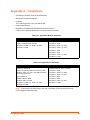
Revision History
Date
Rev.
Comments
September 2011
A
Initial Document for firmware release 7.2.0.0.
October 2011
B
Updated power cord part number information.
November 2011
C
Updated ethernet port information and cover product image.
November 2011
D
Added Suppliers Declaration of Conformity document.
EDS-MD User Guide
2
Table of Contents
Copyright & Trademark ______________________________________________________ 2
Warranty _________________________________________________________________ 2
Contacts _________________________________________________________________ 2
Disclaimer ________________________________________________________________ 2
Revision History ___________________________________________________________ 2
List of Figures ____________________________________________________________ 12
List of Tables _____________________________________________________________ 13
1: Using This Guide
15
Purpose and Audience _____________________________________________________ 15
Summary of Chapters ______________________________________________________ 15
Safety Information _________________________________________________________ 16
Cover _______________________________________________________________ 16
Power Plug ___________________________________________________________ 16
Input Supply __________________________________________________________ 16
Grounding ____________________________________________________________ 16
Fuses _______________________________________________________________ 16
Battery ______________________________________________________________ 17
Wall Mounting _________________________________________________________ 17
Port Connections ______________________________________________________ 17
Equipment Classifications _______________________________________________18
Environmental Conditions for Transportation and Storage _______________________ 18
Cleaning Instructions ___________________________________________________ 18
Electromagnetic Interference _____________________________________________ 18
Additional Documentation ___________________________________________________ 19
2: Introduction
20
Key Features _____________________________________________________________ 20
Applications ______________________________________________________________ 20
Protocol Support
_________________________________________________________ 20
Troubleshooting Capabilities _________________________________________________ 21
Configuration Methods _____________________________________________________ 21
Addresses and Port Numbers ________________________________________________ 21
Hardware Address _____________________________________________________ 21
IP Address ___________________________________________________________ 21
Port Numbers _________________________________________________________ 22
Product Information Label ___________________________________________________ 22
EDS-MD User Guide
3
3: Installation of EDS-MD4/8/16 Device Servers
23
Package Contents _________________________________________________________ 23
User-Supplied Items _______________________________________________________ 23
Identifying Hardware Components ____________________________________________ 23
Serial Ports ___________________________________________________________ 24
Ethernet Port _________________________________________________________ 24
LEDs ________________________________________________________________ 24
Reset to Default Button _________________________________________________ 25
To restore factory default settings: ______________________________________ 25
Technical Specification _____________________________________________________ 26
Installing the EDS-MD ______________________________________________________ 27
Finding a Suitable Location ______________________________________________ 27
Connect the EDS-MD to one or more serial devices ___________________________ 27
4: Using DeviceInstaller
28
Accessing EDS-MD Using DeviceInstaller ______________________________________ 28
Device Detail Summary _____________________________________________________ 28
5: Configuration Using Web Manager
30
Accessing Web Manager ___________________________________________________ 30
Device Status Page ____________________________________________________ 31
Web Manager Page Components _____________________________________________ 32
Navigating the Web Manager ________________________________________________ 33
6: Line and Tunnel Settings
35
RS232/RS485 _________________________________________________________ 35
Line Settings _____________________________________________________________ 35
To Configure Line Settings _______________________________________________36
Using Web Manager ________________________________________________ 36
Using the CLI ______________________________________________________ 36
Using XML ________________________________________________________ 36
To View Line Statistics __________________________________________________ 36
Using Web Manager ________________________________________________ 36
Using the CLI ______________________________________________________ 37
Using XML ________________________________________________________ 37
Tunnel Settings ___________________________________________________________ 37
Serial Settings ________________________________________________________ 37
To Configure Tunnel Serial Settings ________________________________________ 37
Using Web Manager ________________________________________________ 37
Using the CLI ______________________________________________________ 38
Using XML ________________________________________________________ 38
Packing Mode _________________________________________________________ 38
EDS-MD User Guide
4
To Configure Tunnel Packing Mode Settings _________________________________ 38
Using Web Manager ________________________________________________ 38
Using the CLI ______________________________________________________ 39
Using XML ________________________________________________________ 39
Accept Mode __________________________________________________________ 39
To Configure Tunnel Accept Mode Settings __________________________________ 40
Using Web Manager ________________________________________________ 40
Using the CLI ______________________________________________________ 40
Using XML ________________________________________________________ 40
Connect Mode ________________________________________________________ 41
To Configure Tunnel Connect Mode Settings ________________________________ 42
Using Web Manager ________________________________________________ 42
Using the CLI ______________________________________________________ 42
Using XML ________________________________________________________ 42
Disconnect Mode ______________________________________________________ 42
To Configure Tunnel Disconnect Mode Settings ______________________________ 43
Using Web Manager ________________________________________________ 43
Using the CLI ______________________________________________________ 43
Using XML ________________________________________________________ 43
Modem Emulation ______________________________________________________ 43
To Configure Tunnel Modem Emulation Settings ______________________________ 44
Using Web Manager ________________________________________________ 44
Using the CLI ______________________________________________________ 44
Using XML ________________________________________________________ 44
Statistics _____________________________________________________________ 44
To View Tunnel Statistics ________________________________________________ 44
Using Web Manager ________________________________________________ 44
Using the CLI ______________________________________________________ 45
Using XML ________________________________________________________ 45
7: Network Settings
46
Network Interface Settings __________________________________________________ 46
To Configure Network Interface Settings ____________________________________ 47
Using Web Manager ________________________________________________ 47
Using the CLI ______________________________________________________ 47
Using XML ________________________________________________________ 47
To View Network Interface Status _________________________________________ 47
Using Web Manager ________________________________________________ 47
Network Link Settings ______________________________________________________ 48
To Configure Network Link Settings ________________________________________ 48
Using Web Manager ________________________________________________ 48
Using the CLI ______________________________________________________ 48
Using XML ________________________________________________________ 48
EDS-MD User Guide
5
8: Terminal and Host Settings
49
Terminal Settings _________________________________________________________ 49
To Configure the Terminal Network Connection _______________________________ 50
Using Web Manager ________________________________________________ 50
Using the CLI ______________________________________________________ 50
Using XML ________________________________________________________ 50
To Configure the Terminal Line Connection __________________________________ 50
Using Web Manager ________________________________________________ 50
Using the CLI ______________________________________________________ 50
Using XML ________________________________________________________ 50
Host Configuration ________________________________________________________ 50
To Configure Host Settings ______________________________________________ 51
Using Web Manager ________________________________________________ 51
Using the CLI ______________________________________________________ 51
Using XML ________________________________________________________ 51
9: Services Settings
52
DNS Settings _____________________________________________________________ 52
To View or Configure DNS Settings: _______________________________________ 52
Using Web Manager ________________________________________________ 52
Using the CLI ______________________________________________________ 52
Using XML ________________________________________________________ 52
FTP Settings _____________________________________________________________ 53
To Configure FTP Settings _______________________________________________53
Using Web Manager ________________________________________________ 53
Using the CLI ______________________________________________________ 53
Using XML ________________________________________________________ 53
Syslog Settings ___________________________________________________________ 53
To View or Configure Syslog Settings: ______________________________________ 54
Using Web Manager ________________________________________________ 54
Using the CLI ______________________________________________________ 54
Using XML ________________________________________________________ 54
HTTP Settings ____________________________________________________________ 54
To Configure HTTP Settings _____________________________________________ 55
Using Web Manager ________________________________________________ 55
Using the CLI ______________________________________________________ 55
Using XML ________________________________________________________ 55
To Configure HTTP Authentication _________________________________________ 56
Using Web Manager ________________________________________________ 56
Using the CLI ______________________________________________________ 56
Using XML ________________________________________________________ 56
RSS Settings _____________________________________________________________ 56
EDS-MD User Guide
6
To Configure RSS Settings ______________________________________________ 56
Using Web Manager ________________________________________________ 56
Using the CLI ______________________________________________________ 57
Using XML ________________________________________________________ 57
Real Time Clock (RTC) Settings ______________________________________________ 57
To Configure RTC Settings ______________________________________________ 57
Using Web Manager ________________________________________________ 57
Using the CLI ______________________________________________________ 57
Using XML ________________________________________________________ 57
10: Security Settings
58
SSH Settings _____________________________________________________________ 58
SSH Server Host Keys __________________________________________________ 58
SSH Client Known Hosts ________________________________________________ 59
SSH Server Authorized Users ____________________________________________ 59
SSH Client Users ______________________________________________________ 60
To Configure SSH Settings ______________________________________________ 61
Using Web Manager ________________________________________________ 61
Using the CLI ______________________________________________________ 61
Using XML ________________________________________________________ 61
SSL Settings _____________________________________________________________ 61
Certificate and Key Generation ___________________________________________ 62
To Create a New Credential ______________________________________________ 62
Using Web Manager ________________________________________________ 62
Using the CLI ______________________________________________________ 62
Using XML ________________________________________________________ 63
Certificate Upload Settings _______________________________________________63
To Configure an Existing SSL Credential ____________________________________ 63
Using Web Manager ________________________________________________ 63
Using the CLI ______________________________________________________ 63
Using XML ________________________________________________________ 63
Trusted Authorities _____________________________________________________ 64
To Upload an Authority Certificate _________________________________________ 64
Using Web Manager ________________________________________________ 64
Using the CLI ______________________________________________________ 64
Using XML ________________________________________________________ 64
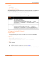
11: Maintenance and Diagnostics Settings
65
Filesystem Settings ________________________________________________________ 65
File Display ___________________________________________________________ 65
To Display Files _______________________________________________________ 65
Using Web Manager ________________________________________________ 65
Using the CLI ______________________________________________________ 65
EDS-MD User Guide
7
Using XML ________________________________________________________ 65
File Modification _______________________________________________________ 66
File Transfer __________________________________________________________ 66
To Transfer or Modify Filesystem Files ______________________________________ 67
Using Web Manager ________________________________________________ 67
Using the CLI ______________________________________________________ 67
Using XML ________________________________________________________ 67
IP Network Stack Settings ___________________________________________________ 67
To Configure IP Network Stack Settings ____________________________________ 67
Using Web Manager ________________________________________________ 67
Using the CLI ______________________________________________________ 67
Using XML ________________________________________________________ 67
To Configure ICMP Network Stack Settings __________________________________ 68
Using Web Manager ________________________________________________ 68
Using the CLI ______________________________________________________ 68
Using XML ________________________________________________________ 68
To Configure ARP Network Stack Settings __________________________________ 68
Using Web Manager ________________________________________________ 68
Using the CLI ______________________________________________________ 68
Using XML ________________________________________________________ 68
To Configure SMTP Network Stack Settings _________________________________ 69
Using Web Manager ________________________________________________ 69
Using the CLI ______________________________________________________ 69
Using XML ________________________________________________________ 69
Query Port _______________________________________________________________ 69
To Configure Query Port Settings _________________________________________ 69
Using Web Manager ________________________________________________ 69
Using the CLI ______________________________________________________ 69
Using XML ________________________________________________________ 70
Diagnostics ______________________________________________________________ 70
Hardware ____________________________________________________________ 70
To View Hardware Information ____________________________________________ 70
Using Web Manager ________________________________________________ 70
Using the CLI ______________________________________________________ 70
Using XML ________________________________________________________ 70
IP Sockets ___________________________________________________________ 70
To View the List of IP Sockets ____________________________________________ 70
Using Web Manager ________________________________________________ 70
Using the CLI ______________________________________________________ 70
Using XML ________________________________________________________ 70
Ping ________________________________________________________________ 70
To Ping a Remote Host _________________________________________________ 71
Using Web Manager ________________________________________________ 71
EDS-MD User Guide
8
Using the CLI ______________________________________________________ 71
Using XML ________________________________________________________ 71
Traceroute ___________________________________________________________ 71
To Perform a Traceroute ________________________________________________ 71
Using Web Manager ________________________________________________ 71
Using the CLI ______________________________________________________ 71
Using XML ________________________________________________________ 71
Log _________________________________________________________________ 72
To Configure the Diagnostic Log Output ____________________________________ 72
Using Web Manager ________________________________________________ 72
Using the CLI ______________________________________________________ 72
Using XML ________________________________________________________ 72
Memory ______________________________________________________________ 72
To View Memory Usage _________________________________________________ 72
Using Web Manager ________________________________________________ 72
Using the CLI ______________________________________________________ 72
Using XML ________________________________________________________ 72
Processes ____________________________________________________________ 73
To View Process Information _____________________________________________ 73
Using Web Manager ________________________________________________ 73
Using the CLI ______________________________________________________ 73
Using XML ________________________________________________________ 73
Threads _________________________________________________________________ 73
To View Thread Information ______________________________________________ 73
Using Web Manager ________________________________________________ 73
Using the CLI ______________________________________________________ 73
Using XML ________________________________________________________ 73
System Settings __________________________________________________________ 74
To Reboot or Restore Factory Defaults _____________________________________ 74
Using Web Manager ________________________________________________ 74
Using the CLI ______________________________________________________ 74
Using XML ________________________________________________________ 74
12: Advanced Settings
75
Email Settings ____________________________________________________________ 75
To View, Configure and Send Email ________________________________________ 75
Using Web Manager ________________________________________________ 75
Using the CLI ______________________________________________________ 76
Using XML ________________________________________________________ 76
Command Line Interface Settings _____________________________________________ 76
Basic CLI Settings _____________________________________________________ 76
To View and Configure Basic CLI Settings ___________________________________ 76
Using Web Manager ________________________________________________ 76
EDS-MD User Guide
9
Using the CLI ______________________________________________________ 76
Using XML ________________________________________________________ 76
Telnet Settings ________________________________________________________ 77
To Configure Telnet Settings _____________________________________________ 77
Using Web Manager ________________________________________________ 77
Using the CLI ______________________________________________________ 77
Using XML ________________________________________________________ 77
SSH Settings _________________________________________________________ 77
To Configure SSH Settings ______________________________________________ 78
Using Web Manager ________________________________________________ 78
Using the CLI ______________________________________________________ 78
Using XML ________________________________________________________ 78
XML Settings _____________________________________________________________ 78
XML: Export Configuration _______________________________________________78
To Export Configuration in XML Format _____________________________________ 79
Using Web Manager ________________________________________________ 79
Using the CLI ______________________________________________________ 79
Using XML ________________________________________________________ 79
XML: Export Status _____________________________________________________ 79
To Export in XML Format ________________________________________________ 79
Using Web Manager ________________________________________________ 79
Using the CLI ______________________________________________________ 79
Using XML ________________________________________________________ 80
XML: Import Configuration _______________________________________________80
Import Configuration from External File _____________________________________ 80
Import Configuration from the Filesystem ____________________________________ 80
To Import Configuration in XML Format _____________________________________ 80
Using Web Manager ________________________________________________ 80
Using the CLI ______________________________________________________ 80
Using XML ________________________________________________________ 80
13: Updating Firmware
81
Obtaining Firmware ________________________________________________________ 81
Loading New Firmware _____________________________________________________ 81
14: VIP Settings
82
Virtual IP (VIP) Configuration ________________________________________________ 82
To Configure VIP Settings _______________________________________________82
Using Web Manager ________________________________________________ 82
Using the CLI ______________________________________________________ 82
Using XML ________________________________________________________ 82
Virtual IP (VIP) Status ______________________________________________________ 82
To View VIP Status _____________________________________________________ 82
EDS-MD User Guide
10
Using Web Manager ________________________________________________ 82
Using the CLI ______________________________________________________ 82
Using XML ________________________________________________________ 83
Virtual IP (VIP) Counters ____________________________________________________ 83
To View VIP Counters __________________________________________________ 83
Using Web Manager ________________________________________________ 83
Using the CLI ______________________________________________________ 83
Using XML ________________________________________________________ 83
15: Branding the EDS-MD4/8/16
84
Web Manager Customization ________________________________________________ 84
Short and Long Name Customization __________________________________________ 85
To Customize Short or Long Names _______________________________________ 85
Using Web Manager ________________________________________________ 85
Using the CLI ______________________________________________________ 85
Using XML ________________________________________________________ 85
Appendix A: Technical Support
86
Appendix B: Binary to Hexadecimal Conversions
87
Converting Binary to Hexadecimal ____________________________________________ 87
Conversion Table ______________________________________________________ 87
Scientific Calculator ____________________________________________________ 87
Appendix C: Compliance
89
Appendix D: Lantronix Cables, Adapters
and Serial Port Pinouts
93
Cables and Adapters _______________________________________________________ 93
Adapters and Serial Port Pinouts _____________________________________________ 94
EDS-MD User Guide
11
List of Figures
Figure 2-1 EDS-MD Product Label ___________________________________________________ 22
Figure 3-1 Front View of the EDS-MD16 ______________________________________________ 24
Figure 3-2 Back View of the EDS-MD4, EDS-MD8 and EDS-MD16 _________________________ 24
Figure 5-1 Components of the Web Manager Page ______________________________________ 32
Figure 17-2 Windows Scientific Calculator _____________________________________________ 88
Figure 17-3 Hexadecimal Values in the Scientific Calculator _______________________________ 88
Figure 18-4 Suppliers Declaration of Conformity ________________________________________ 91
Figure 19-2 RJ45 Receptacle to DB25M DTE Adapter (PN 200.2066A) ______________________ 94
Figure 19-3 RJ45 Receptacle to DB25M DCE Adapter (PN 200.2073) _______________________ 94
Figure 19-4 RJ45 Receptacle to DB25F DTE Adapter (PN 200.2067A )______________________ 95
Figure 19-5 RJ45 Receptacle to DB25F DCE Adapter (PN 200.2074) _______________________ 95
Figure 19-6 RJ45 Receptacle to DB9M DTE Adapter (PN 200.2069A)_______________________ 96
Figure 19-7 RJ45 Receptacle to DB9M DCE Adapter (PN 200.2071)________________________ 96
Figure 19-8 RJ45 Receptacle to DB9F DTE Adapter (PN 200.2070A)________________________ 97
Figure 19-9 RJ45 Receptacle to DB9F DCE Adapter (PN 200.2072) ________________________ 97
Figure 19-10 RJ45 to RJ45 Adapter (ADP010104-01) ____________________________________ 98
EDS-MD User Guide
12
List of Tables
Table 3-3 System LEDs on the Top of EDS-MD ________________________________________ 24
Table 3-4 Serial Indicator LEDs on the Top of EDS-MD __________________________________ 25
Table 3-5 RJ45 LEDs on the Back Panel (Ethernet Indicators). ____________________________ 25
Table 6-1 Line Configuration Settings ________________________________________________ 35
Table 6-2 Line Command Mode Settings ______________________________________________ 36
Table 6-3 Tunnel Serial Settings ____________________________________________________ 37
Table 6-4 Tunnel Packing Mode Settings _____________________________________________ 38
Table 6-5 Tunnel Accept Mode Settings ______________________________________________ 39
Table 6-6 Tunnel Connect Mode Settings _____________________________________________ 41
Table 6-7 Tunnel Disconnect Mode Settings ___________________________________________ 42
Table 6-8 Tunnel Modem Emulation Settings __________________________________________ 43
Table 7-1 Network Interface Settings _________________________________________________ 46
Table 7-2 Network 1 (eth0) Link Settings ______________________________________________ 48
Table 8-1 Terminal on Network and Line Settings _______________________________________ 49
Table 8-2 Host Configuration _______________________________________________________ 50
Table 9-1 DNS Settings ___________________________________________________________ 52
Table 9-2 FTP Settings ___________________________________________________________ 53
Table 9-3 Syslog Settings _________________________________________________________ 53
Table 9-4 HTTP Settings __________________________________________________________ 54
Table 9-5 HTTP Authentication Settings ______________________________________________ 55
Table 9-6 RSS Settings ___________________________________________________________ 56
Table 9-7 RTC Settings ___________________________________________________________ 57
Table 10-1 SSH Server Host Keys ___________________________________________________ 58
Table 10-2 SSH Client Known Hosts _________________________________________________ 59
Table 10-3 SSH Server Authorized Users _____________________________________________ 60
Table 10-4 SSH Client Users _______________________________________________________ 60
Table 10-5 Certificate and Key Generation Settings _____________________________________ 62
Table 10-6 Upload Certificate Settings _______________________________________________63
Table 10-7 Trusted Authority Settings ________________________________________________ 64
Table 11-1 File Display Settings ____________________________________________________ 65
Table 11-2 File Modification Settings _________________________________________________ 66
Table 11-3 File Transfer Settings ____________________________________________________ 66
Table 11-4 IP Network Stack Settings ________________________________________________ 67
Table 11-5 ICMP Network Stack Settings _____________________________________________ 68
Table 11-6 ARP Network Stack Settings ______________________________________________ 68
Table 11-7 SMTP Network Stack Settings _____________________________________________ 69
EDS-MD User Guide
13
Table 11-8 Query Port Settings _____________________________________________________ 69
Table 11-9 Ping Settings __________________________________________________________ 71
Table 11-10 Traceroute Settings ____________________________________________________ 71
Table 11-11 Log Settings __________________________________________________________ 72
Table 11-12 System Settings _______________________________________________________ 74
Table 12-1 Email Configuration _____________________________________________________ 75
Table 12-2 CLI Configuration Settings ________________________________________________ 76
Table 12-3 Telnet Settings ________________________________________________________ 77
Table 12-4 SSH Settings __________________________________________________________ 77
Table 12-5 XML Exporting Configuration ______________________________________________ 78
Table 12-6 Exporting Status ________________________________________________________ 79
Table 12-7 Import Configuration from Filesystem Settings ________________________________ 80
Table 14-1 VIP Configuration _______________________________________________________ 82
Table 14-2 VIP Counters __________________________________________________________ 83
Table 15-1 Short and Long Name Settings ____________________________________________ 85
Table 17-1 Binary to Hexadecimal Conversion _________________________________________ 87
Table 18-1 Applicable Medical Standards _____________________________________________ 89
Table 18-2 Applicable ITE Standards ________________________________________________ 89
Table 18-3 Regulatory Compliance __________________________________________________ 90
Table 19-1 Lantronix Cables and Adapters ____________________________________________ 93
EDS-MD User Guide
14
1:
Using This Guide
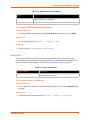
Purpose and Audience
This guide provides the information needed to configure, use, and update the EDS-MD4, EDSMD8 and EDS-MD16. It is intended for system integrators who are installing this product into their
designs.
Note: EDS-MD device servers (which include models EDS-MD4, EDS-MD8 and
EDSMD16) are commonly referred to as either EDS-MD4/8/16 or as EDS-MD when
mentioned within a description equally applicable to any of the three models.
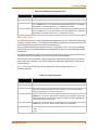
Summary of Chapters
The remaining chapters in this guide include:
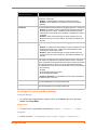
Chapter
Description
2: Introduction
Main features of the product and the protocols it supports.
Includes technical specifications.
3: Installation of EDS-MD4/8/16 Device
Servers
Instructions for installing the EDS-MD.
4: Using DeviceInstaller
Instructions for viewing the current configuration using
DeviceInstaller.
5: Configuration Using Web Manager
Instructions for accessing Web Manager and using it to configure
settings for the device.
7: Network Settings
Instructions for configuring network settings.
6: Line and Tunnel Settings
Instructions for configuring line and tunnel settings.
8: Terminal and Host Settings
Instructions for configuring terminal and host settings.
9: Services Settings
Instructions for configuring DNS, FTP, HTTP and Syslog settings.
10: Security Settings
Instructions for configuring SSL security settings.
11: Maintenance and Diagnostics
Settings
Instructions to maintain the EDS-MD, view statistics, files, and
diagnose problems.
12: Advanced Settings
Instructions for configuring email, CLI and XML settings.
13: Updating Firmware
Instructions for obtaining the latest firmware and updating the
EDS-MD.
14: VIP Settings
Information about Virtual IP (VIP) features available on the device
and instructions on configuring settings.
15: Branding the EDS-MD4/8/16
Instructions on how to brand your device.
Appendix A: Technical Support
Instructions for contacting Lantronix Technical Support.
Appendix B: Binary to Hexadecimal
Conversions
Instructions for converting binary values to hexadecimals.
Appendix C: Compliance
Lantronix compliance information.
Appendix D: Lantronix Cables,
Adapters and Serial Port Pinouts
Information about the device driver for windows host.
EDS-MD User Guide
15
1: Using This Guide
Safety Information
This section describes the safety precautions that should be followed when installing and
operating the EDS-MD.
Warning:
This equipment is not suitable for use in the presence of a flammable
anaesthetic mixture including air, oxygen or nitrous oxide.
Cover
Warning:
Note:
Do not remove the cover of the EDS-MD. There are no user-serviceable
parts inside. Opening or removing the cover may expose you to
dangerous voltage that could cause fire or electric shock. Do not
operate the EDS-MD if the housing is broken.
Refer all servicing to Lantronix.
Power Plug
When disconnecting the power cable from the socket, pull on the plug, not the cord.
Always connect the power cord to a properly wired and grounded power source. Do not use
adapter plugs or remove the grounding prong from the cord.
Only use a power cord with a voltage and current rating greater than the voltage and current
rating marked on the unit.
Note:
Unit is shipped with a power cord for medical application.
Install the unit near an AC outlet that is easily accessible.
Always connect any equipment used with the product to properly wired and grounded power
sources.
To help protect the product from sudden, transient increases and decreases in electrical
power, use a surge suppressor, line conditioner, or uninterruptible power supply (UPS).
Do not connect or disconnect this product during an electrical storm.
Input Supply
Check nameplate ratings to assure there is no overloading of supply circuits that could affect
over current protection and supply wiring.
Grounding
Maintain reliable grounding of this product.
Pay particular attention to supply connections when connecting to power strips, rather than
directly to the branch circuit.
Fuses
There are fuses on the internal power supply serviceable only by Lantronix.
EDS-MD User Guide
16
1: Using This Guide
Battery
A Lithium battery cell inside the unit maintains the unit's date and time when the device is powered
off. Do not attempt to replace it. The battery is serviceable only by Lantronix.
Caution:
Attention:
DANGER OF EXPLOSION IF BATTERY IS INCORRECTLY REPLACED.
REPLACE ONLY WITH THE SAME OR EQUIVALENT TYPE
RECOMMENDED BY THE MANUFACTURER. DISPOSE OF USED
BATTERIES ACCORDING TO THE MANUFACTURER'S INSTRUCTIONS.
IL Y A DANGER D'EXPLOSION S'IL Y A REMPLACEMENT INCORRECT
DE LA BATTERIE, REMPLACER UNIQUEMENT AVEC UNE BATTERIE
DU MÊME TYPE OU D'UN TYPE ÉQUIVALENT RECOMMANDÉ PAR LE
CONSTRUCTEUR. METTRE AU REBUT LES BATTERIES USAGÉES
CONFORMÉMENT AUX INSTRUCTIONS DU FABRICANT.
Wall Mounting
If wall-mounted units are installed, the following items must be considered:
Do not install the unit in such a way that a hazardous stability condition results because of
uneven loading. A drop or fall could cause injury.
Make sure to install the EDS-MD in an environment with an ambient temperature less than the
maximum operating temperature of the EDS-MD. Therefore, consideration should be given to
installing the equipment in an environment compatible with the maximum ambient temperature
(Tma) specified by the manufacturer.
Install the equipment on a wall in such a way that the amount of airflow required for safe
operation of the equipment is not compromised.
Maintain reliable earthing of wall-mounted equipment. Give particular attention to supply
connections other than direct connections to the branch circuit (e.g. use of power strips)
because of the effect that overloading of the circuits might have on overcurrent protection and
supply wiring. Appropriate consideration of equipment nameplate ratings should be used
when addressing this concern.
Before operating the EDS-MD, make sure the EDS-MD mounting is secured.
Port Connections
Only connect the network port to an Ethernet network that supports 10 Base-T/100 Base-TX/
1000 Base-T.
Only connect device ports to equipment with serial ports that support EIA-232 (formerly RS232C).
Unless specified otherwise, only connect USB ports to USB thumb drives.
Warning:
To avoid overloading and overheating, do not use a USB port as a
charger port or a power port for other devices such as a cellular phone,
PDA device, disk drive, etc.
EDS-MD User Guide
17
1: Using This Guide
Equipment Classifications
Classification according to the type of protection against electric shock: Class I Equipment
Classification according to the degree of protection against electric shock: No Applied Parts
Classification according to the degree of protection against ingress of water: IP20
Classification according to the mode of operation: Continuous Operation
Environmental Conditions for Transportation and Storage
An ambient temperature range of -30°C to +80°C
A relative humidity range of 0% to 95%, noncondensing
An atmospheric pressure range of 50 kPa to 106 kPa
Cleaning Instructions
1. Disconnect all cables and unplug ac power from the device.
2. Prepare a disinfectant solution using 1 part bleach mixed with 9 parts water.
3. Lightly moisten a tissue with the mild detergent and wipe down only the outside of the device.
4. Allow the device to air-dry or wipe dry with a clean dry tissue before use.
Caution:
To avoid electric shock and for the device to work properly, do not allow
cleaning solution get inside the device, specifically the interface port
connectors or the ac inlet. Do not immerse the device in any liquid.
Electromagnetic Interference
This equipment has been tested and found to comply with the EMC limits for the Medical Device
Directive 93/42/EEC (EN 55022 Class A and EN 60601-1-2). These limits are designed to provide
reasonable protection against harmful interference in a typical medical installation. The equipment
generates, uses and can radiate radio frequency energy and, if not installed and used in
accordance with these instructions, may cause harmful interference to other devices in the vicinity.
However, there is no guarantee that interference will not occur in a particular installation. If this
equipment does cause harmful interference with other devices, which can be determined by
turning the equipment off and on, the user is encouraged to try to correct the interference by one
or more of the following measures:
Reorient or relocate the receiving device
Increase the separation between the equipment
Connect the equipment into an outlet on a circuit different from that to which the other
device(s) is connected
Consult the manufacturer or field service technician for help
EDS-MD User Guide
18
1: Using This Guide
Additional Documentation
Visit the Lantronix Web site at www.lantronix.com/support/documentation for the latest
documentation and the following additional documentation.
Document
Description
EDS-MD Command Reference
Instructions for accessing Command Mode (the command line
interface) using a Telnet connection, SSH connection or through the
serial port. Detailed information about the commands. Also provides
details for XML configuration and status.
EDS-MD Quick Start Guide
Instructions for getting the EDS-MD up and running.
DeviceInstaller Online Help
Instructions for using the Lantronix Windows-based utility to locate the
EDS-MD and to view its current settings.
Com Port Redirector Quick Start Instructions for using the Lantronix Windows-based utility to create
and Online Help
virtual com ports.
Secure Com Port Redirector
User Guide
EDS-MD User Guide
Instructions for using the Lantronix Windows-based utility to create
secure virtual com ports.
19
2:
Introduction
The EDS-MD4, EDS-MD8 and EDS-MD16 Ethernet Device Servers are complete networkenabling solutions. This device server allows system integrators and administrators to go to
market quickly and easily with Ethernet networking and web server capabilities. EDS-MD models
are available in 4, 8 and 16 port configurations.
Key Features
Power Supply: Direct plug-in to wall ac with universal 100-240 VAC input
Controller: 32-bit ARM11 microprocessor running at 600 megahertz (Mhz)
Memory: 64 megabit Flash, 2 gigabit DDR2 DRAM, and a 4 gigabyte SDHC card (internal
only-not user replaceable).
Ethernet: Gigabit Ethernet support (10/100/1000Base-T) speed auto-sensing, automatic MDI/
MDIX (straight and cross-over cables are OK to use)
Serial Ports: 4 to 16 ports depending on model (EDS-MD4, EDS-MD8 or EDS-MD16),
electrically isolated from one another and other circuits. Hardware/Software handshaking
capability. Custom/standard baud rates up to 921600 bits per second (bps).
USB ports: 2 ports of fixed full-speed 2.0 USB Host, electrically isolated from one another and
other circuits, capable of providing 0.5A each.
Temperature Range: 0°C to +55°C.
Applications
The EDS-MD4/8/16 device server connects serial devices such as those listed below to Ethernet
networks using the IP protocol family.
Patient Monitoring Devices
Glucose Analyzers
Infusion Pumps
Protocol Support
The EDS-MD4/8/16 device server contains a full-featured IP stack. Supported protocols include:
ARP, UDP, TCP, ICMP, DHCP, Auto IP, Telnet, SMTP, DNS, FTP, TFTP, and Syslog for
network communications and management.
TCP, UDP and tunneling to the serial port.
TFTP for uploading/downloading files.
FTP, SFTP, HTTPS and HTTP for firmware upgrades and uploading/downloading files.
EDS-MD User Guide
20
2: Introduction
Troubleshooting Capabilities
The EDS-MD4/8/16 offers a comprehensive diagnostic toolset that lets you troubleshoot problems
quickly and easily. Available from the CLI or Web Manager, the diagnostic tools let you:
View memory and IP socket information.
Perform ping and traceroute operations.
Conduct forward or reverse DNS lookup operations.
View all processes currently running on the EDS-MD, including CPU utilization.
View system log messages.
Configuration Methods
After installation, the EDS-MD4/8/16 requires configuration. For the unit to operate correctly on a
network, it must have a unique IP address on the network. There are four basic methods for
logging into the EDS-MD4/8/16 and assigning IP addresses and other configurable settings:
Web Manager: View and configure all settings easily through a web browser using the Lantronix
Web Manager. (See “Configuration Using Web Manager” on page 30.)
DeviceInstaller: Configure the IP address and related settings and view current settings on the
EDS-MD4, EDS-MD8 and EDS-MD16 using a Graphical User Interface (GUI) on a PC attached to
a network. (See “Using DeviceInstaller” on page 28.)
Command Mode: There are two methods for accessing Command Mode (CLI): making a Telnet
or SSH connection, or connecting a terminal (or a PC running a terminal emulation program) to the
unit’s serial port. (See the EDS-MD4 Command Reference Guide for instructions and available
commands.)
XML: The EDS-MD4/8/16 supports XML-based configuration and setup records that make device
configuration transparent to users and administrators. XML is easily editable with a standard text
or XML editor. (See the EDS-MD Command Reference Guide for instructions and commands.)
Addresses and Port Numbers
Hardware Address
The hardware address is also referred to as the Ethernet address, physical address, or MAC
address. Sample hardware address:
00-20-4A-14-01-18
00:20:4A:14:01:18
IP Address
Every device connected to an IP network must have a unique IP address. This address references
the specific unit.
EDS-MD User Guide
21
2: Introduction
Port Numbers
Every TCP connection and every UDP datagram is defined by a destination and source IP
address, and a destination and source port number. For example, a Telnet server commonly uses
TCP port number 23.
The following is a list of the default server port numbers running on the EDS-MD4/8/16:
TCP Port 22: SSH Server (Command Mode configuration)
TCP Port 23: Telnet Server (Command Mode configuration)
TCP Port 80: HTTP (Web Manager configuration)
TCP Port 21: FTP
UDP Port 30718: LDP (Lantronix Discovery Protocol) port
TCP/UDP Port 10001: Tunnel 1
Note: Additional TCP/UDP ports and tunnels will be available, depending on the product
type. The default numbering of each additional TCP/UDP port and corresponding tunnel
will increase sequentially (i.e., TCP/UDP Port 1000X: Tunnel X).
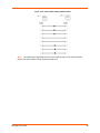
Product Information Label
The product information label on the unit contains the
following information about the specific unit:
Bar code
Product Revision
Part Number
Serial Number (MAC Address)
Manufacturing Date Code
Note: The hardware address on the
label is also the product serial number.
The hardware address on the label is the
address for the Ethernet (eth0) interface.
Figure 2-1 EDS-MD Product Label
Bar Code
Serial Number
SN:
XXXXXXXXXXXXX
Part Number
PN:
XXXXXXXXXXXXX
Made In:
EDS-MD User Guide
XXXXXXX
Rev: XXX
Revision
YYWWW
Manufacturing
Date Code
22
3:
Installation of EDS-MD4/8/16 Device Servers
This chapter describes how to install the EDS-MD4, EDS-MD8 and EDS-MD16 device servers.
Package Contents
Your EDS-MD4/8/16 package includes the following items:
One EDS-MD device server (an EDS-MD4, EDS-MD8 or EDS-MD16)
One RJ45 CAT 5E cable (part number 500-207-R) for network connection
One RJ45 cable loopback adapter (part number 500-153)
One power cord
EDS-MD Quick Start Guide
User-Supplied Items
To complete your EDS-MD installation, you need the following items:
RS-232 serial devices that require network connectivity. Each EDS-MD4/8/16 serial port
supports a directly connected RS-232 serial device.
A serial cable for each serial device to be connected to the EDS-MD4/8/16. All devices
attached to the device ports support the RS-232C (EIA-232) standard. Category 5 cabling with
RJ45 connections is used for the device port connections.
Note: To connect an EDS-MD4/8/16 serial port to a DTE device, you need a DTE cable,
such as the one supplied in your EDS-MD package, or an RJ45 patch cable and DTE
adapter. To connect the EDS-MD4/8/16 serial port to a DCE device, you need a DCE
(modem) cable, or an RJ45 patch cable and DCE adapter. For a list of the Lantronix
cables and adapters you can use with the EDS-MD, see the Appendix D: Lantronix
Cables, Adapters and Serial Port Pinouts (on page 93).
An available connection to your Ethernet network and an Ethernet cable.
A working, properly grounded power outlet.
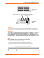
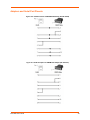
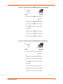
Identifying Hardware Components
Figure 3-1 shows the front of the EDS-MD16. Figure 3-2 shows the back of the EDS-MD4, EDSMD8 or EDS-MD16.
EDS-MD User Guide
23
3: Installation of EDS-MD4/8/16 Device Servers
Figure 3-1 Front View of the EDS-MD16
Note: EDS-MD4
has 4 RJ45 Serial
Ports and EDS-MD8
has 8 RJ45 Serial
Ports.
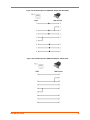
Figure 3-2 Back View of the EDS-MD4, EDS-MD8 and EDS-MD16
USB Port
RJ45 Ethernet Ports
Note: Ethernet ports
2 and 3 will become
operational with a
future firmware
update.
Power Connector
Serial Ports
In the front of the device, the EDS-MD4 has 4 serial ports, the EDS-MD8 has 8 serial ports, and
the EDS-MD16 has 16 serial ports. All are configured as DTE and support up to 921600 baud.
Ethernet Port
The back panel of the EDS-MD4/8/16 provides a network interface via the “Main 1” RJ45 port. This
port can connect to an Ethernet network at 10/100/1000Base-T. The Speed LED on the back of
the EDS-MD shows the connection of the attached Ethernet network. The EDS-MD4/8/16 can be
configured to operate at a fixed Ethernet speed and duplex mode (half- or full-duplex). Otherwise
by default, the EDS-MD auto-negotiates the connection to the Ethernet network.
LEDs
Light-emitting diodes (LEDs) on the EDS-MD show status information.
Each serial port has a corresponding status LED.
The Ethernet port LEDs indicate Speed, Activity, Power, and Status.
The tables below describe the LEDs on the EDS-MD4, EDS-MD8 or EDS-MD16.
Table 3-3 System LEDs on the Top of EDS-MD
LED
Description
Steady Green
Unit operational.
Off
Unit powered down or not operational.
EDS-MD User Guide
24
3: Installation of EDS-MD4/8/16 Device Servers
Table 3-4 Serial Indicator LEDs on the Top of EDS-MD
LED
Description
Green
Indicates there is a tunnel connection to or from the EDS-MD.
Red
Not supported.
Off
There is no tunnel connection on the serial line.
Note: Number of Serial LEDs correspond with the EDS-MD model number. For
instance, EDS-MD4 has 4 LEDs, EDS-MD8 has 8 LEDs, and EDS-MD16 has 16 LEDs.
Table 3-5 RJ45 LEDs on the Back Panel (Ethernet Indicators).
LED
Description
Left LED Green
Connected at 1000 Mbps.
Left LED Amber
Connected at 100 Mbps.
Left LED Off
Connected at 10 Mbps or no link.
Right LED Green (Solid)
Full duplex with no activity
Right LED Green (Blinking)
Full duplex with activity
Right LED Amber (Solid)
Half duplex with no activity.
Right LED Amber (Blinking)
Half duplex with activity.
Right LED Off
No connection.
Reset to Default Button
The EDS-MD can be restored to factory defaults which includes clearing all networking settings.
The IP address, gateway and netmask are set to all zeros. The reset-to-default button is located
on the side of the housing, accessible with a paper clip or other similar object, through a pin hole.
To restore factory default settings:
1. Power cycle the unit.
2. During the bootup, hold down the reset-to-default button for a minimum of 25 seconds.
3. Release the button. The firmware restores factory default settings to the configuration.
EDS-MD User Guide
25
3: Installation of EDS-MD4/8/16 Device Servers
Technical Specification
Category
Description
NETWORK INTERFACE
Ethernet Ports
3 RJ45 10Base-T/100Base-TX/1000Base-T Ethernet ports
Auto sensing
Automatic MDI/MDI-X crossover
Full duplex IEEE 802.3x flow control
Half-duplex back pressure flow control
Left LED Indicator
See Table 3-5.
Right LED Indicator
See Table 3-5.
Isolation from internal circuit
1.5 KVAC
Isolation from adjacent port
1.5 KVAC
USB INTERFACE
USB Ports
2 of USB-A Host, USB 2.0, Full Speed only
Output Capability
0.5 A
Isolation from internal circuit
1.5 KVAC
Isolation from adjacent port
1.5 KVAC
SERIAL INTERFACE
Serial Ports
Options of 4-port, 8-port, 16-port
RS232 Serial Ports DTE via RJ45 connectors
Baud rate
Selectable from 300 bps to 921600 bps
Serial Line Formats
Characters: 7 or 8 data bits
Stop bits: 1 or 2
Parity: odd, even, none
Modem Control
DTR/DSR
Flow Control
Hardware: CTS/RTS
Software: XON/XOFF
Serial LED Indicators
See Table 3-4.
Protection from ESD
15kV (human body model)
Isolation from internal circuit
1.5 KVAC
Isolation from adjacent port
1.5 KVAC
Reset-to-Default-Parameters
Switch
Side panel pin-hole recessed push button switch
POWER RATING
Power Input AC Connector
IEC60320 C14 receptacle with no power switch
Power Usage
100-240 VAC, 50/60 HZ, 0.4M
EDS-MD User Guide
26
3: Installation of EDS-MD4/8/16 Device Servers
Category (continued)
Description
PHYSICALS
Dimensions
L x W x H = 8.25 x 7.5 x 2.4 in. (21 x 19 x 6 cm)
Weight
16-port = 2.0 lbs (0.9 Kg)
8-port = 1.8 lbs (0.82 Kg)
4-port = 1.75 lbs (0.8 Kg)
Environmental
Temperature Operating 0° to 55°C (32° to 131°F)
Temperature for Transportation and Storage -30° to 80°C
Humidity 0% to 95% non-condensing
Atmospheric Pressure 50 kPa to 105 kPa
Humidity Operating
20% to 90% relative humidity, non-condensing
Installing the EDS-MD
Finding a Suitable Location
You can install the EDS-MD4, EDS-MD8 or EDS-MD16 either on a shelf, on a desktop or
mounted on the wall.
If using AC power, do not use outlets controlled by a wall switch.
Connect the EDS-MD to one or more serial devices
All EDS-MD serial ports support RS-232 devices.
1. Power off the serial devices.
2. Attach a CAT 5 serial cable between the EDS-MD and your serial device. See Appendix D:
Lantronix Cables, Adapters and Serial Port Pinouts (on page 93), for a list of cables and
adapters you can use.
3. Connect an Ethernet cable between the EDS-MD Ethernet port and your Ethernet network.
4. Insert the power cord into the back of the EDS-MD. Plug the other end into an AC wall outlet.
5. Power up the serial devices.
EDS-MD User Guide
27
4:
Using DeviceInstaller
This chapter covers the steps for locating a EDS-MD4/8/16 unit and viewing its properties and
device details. DeviceInstaller is a free utility program provided by Lantronix that discovers,
configures, upgrades and manages Lantronix Device Servers.
Notes:
For instructions on using DeviceInstaller to configure the IP address and related
settings or for more advanced features, see the DeviceInstaller Online Help.
Auto IP generates a random IP address in the range of 169.254.0.1 to
169.254.255.254, with a netmask of 255.255.0.0, if no BOOTP or DHCP server is
found. These addresses are not routable.
Accessing EDS-MD Using DeviceInstaller
Note: Make note of the MAC address. It is needed to locate the EDS-MD4/8/16 using
DeviceInstaller.
To use the DeviceInstaller utility, first install the latest version from the downloads page on the
Lantronix web site www.lantronix.com/downloads.
1. Run the executable to start the installation process and respond to the installation wizard
prompts. (If prompted to select an installation type, select Typical.)
2. Click Start -> All Programs -> Lantronix -> DeviceInstaller -> DeviceInstaller.
3. When DeviceInstaller starts, it will perform a network device search. To perform another
search, click Search.
4. Expand the EDS-MD4, EDS-MD8 or EDS-MD16 folder by clicking the + symbol next to the
folder icon. The list of available Lantronix EDS-MD4/8/16 devices appears.
5. Select the EDS-MD4/8/16 unit by expanding its entry and clicking on its IP address to view its
configuration.
6. On the right page, click the Device Details tab. The current EDS-MD4/8/16 configuration
appears. This is only a subset of the full configuration; the full configuration may be accessed
via Web Manager, CLI or XML.
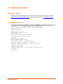
Device Detail Summary
Note:
The settings are Display Only in this table unless otherwise noted
Current Settings
Description
Name
Name identifying the EDS-MD.
DHCP Device Name
The name associated with the EDS-MD module’s current IP address, if
the IP address was obtained dynamically.
EDS-MD User Guide
28
4: Using DeviceInstaller
Current Settings (continued)
Description
Group
Configurable field. Enter a group to categorize the EDS-MD. Doubleclick the field, type in the value, and press Enter to complete. This group
name is local to this PC and is not visible on other PCs or laptops using
DeviceInstaller.
Comments
Configurable field. Enter comments for the EDS-MD. Double-click the
field, type in the value, and press Enter to complete. This description or
comment is local to this PC and is not visible on other PCs or laptops
using DeviceInstaller.
Device Family
Shows the EDS device family type as “EDS”.
Type
Shows the device type as “EDS-MD”.
ID
Shows the EDS-MD ID embedded within the unit.
Hardware Address
Shows the EDS-MD hardware (MAC) address.
Firmware Version
Shows the firmware currently installed on the EDS-MD.
Extended Firmware Version
Provides additional information on the firmware version.
Online Status
Shows the EDS-MD status as Online, Offline, Unreachable (the EDSMD is on a different subnet), or Busy (the EDS-MD is currently
performing a task).
IP Address
Shows the EDS-MD current IP address. To change the IP address, click
the Assign IP button on the DeviceInstaller menu bar.
Appears “Dynamically” if the EDS-MD automatically received an IP
address (e.g., from DHCP). Appears “Statically” if the IP address was
configured manually.
IP Address was Obtained
If the IP address was assigned dynamically, the following fields appear:
Subnet Mask
Gateway
Obtain via DHCP with values of True or False.
Obtain via BOOTP with values of True or False.
Shows the subnet mask specifying the network segment on which the
EDS-MD resides.
Shows the IP address of the router of this network.
There is no default.
Number of Ports
Shows the number of serial ports on this EDS-MD.
Supports Configurable Pins
Shows False, indicating configurable pins are not available on the EDSMD.
Supports Email Triggers
Shows True, indicating email triggers are available on the EDS-MD.
Telnet Enabled
Indicates whether Telnet is enabled on this EDS-MD.
Telnet Port
Shows the EDS-MD port for Telnet sessions.
Web Enabled
Indicates whether Web Manager access is enabled on this EDS-MD.
Web Port
Shows the EDS-MD port for Web Manager configuration (if Web
Enabled field is True).
Firmware Upgradable
Shows True, indicating the EDS-MD firmware is upgradable as newer
versions become available.
EDS-MD User Guide
29
5:
Configuration Using Web Manager
This chapter describes how to configure the EDS-MD4, EDS-MD8 and EDS-MD16 using Web
Manager, the Lantronix browser-based configuration tool. The unit’s configuration is stored in
nonvolatile memory and is retained without power. All changes take effect immediately, unless
otherwise noted. It contains the following sections:
Accessing Web Manager
Web Manager Page Components
Navigating the Web Manager
Accessing Web Manager
Note: You can also access the Web Manager by selecting the Web Configuration tab on
the DeviceInstaller window.
To access Web Manager, perform the following steps:
1. Open a standard web browser. Lantronix supports the latest version of Internet Explorer,
Mozilla Suite, Mozilla Firefox, Safari, Chrome or Opera.
2. Enter the IP address of the EDS-MD4/8/16 in the address bar. The IP address may have been
assigned manually using DeviceInstaller (see the EDS-MD Quick Start Guide) or automatically
by DHCP.
3. Enter your username and password.The factory-default username is “admin” and the
password is “PASS.” The Device Status web page displays configuration, network settings,
line settings, tunneling settings, and product information.
Note: The Logout button is available on any web page. Logging out of the web page
would force re-authentication to take place the next time the web page is accessed.
EDS-MD User Guide
30
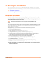
5: Configuration Using Web Manager
Device Status Page
The Device Status page is the first page that appears after you log into the Web Manager. It also
appears when you click Status in the Main Menu.
EDS-MD User Guide
31
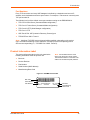
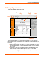
5: Configuration Using Web Manager
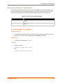
Web Manager Page Components
The layout of a typical Web Manager page is below.
Figure 5-1 Components of the Web Manager Page
Items to
configure
Links to
subpages
Logout
button
Header
Menu Bar
Footer
Configuration and/or Status Area
Information
and Help Area
The menu bar always appears at the left side of the page, regardless of the page shown. The
menu bar lists the names of the pages available in the Web Manager. To bring up a page, click it in
the menu bar.
The main area of the page has these additional sections:
At the very top, many pages, such as the one in the example above, enable you to link to
sub pages. On some pages, you must also select the item you are configuring, such as a
line or a tunnel.
In the middle of many pages, you can select or enter new configuration settings. Some
pages show status or statistics in this area rather than allow you to enter settings.
At the bottom of most pages, the current configuration is displayed. In some cases, you
can reset or clear a setting.
EDS-MD User Guide
32
5: Configuration Using Web Manager
The information or help area shows information or instructions associated with the page.
A Logout link is available at the upper right corner of every web page. In Chrome or
Safari, it is necessary to close out of the browser to completely logout. If necessary,
reopen the browser to log back in.
The footer appears at the very bottom of the page. It contains copyright information and a
link to the Lantronix home page.
Navigating the Web Manager
The Web Manager provides an intuitive point-and-click interface. A menu bar on the left side of
each page provides links you can click to navigate from one page to another. Some pages are
read-only, while others let you change configuration settings.
Note: There may be times when you must reboot the EDS-MD4/8/16 for the new
configuration settings to take effect. The chapters that follow indicate when a change
requires a reboot. Anytime you reboot the unit, this operation will take some time to
complete. Please wait a minimum of 5 seconds after rebooting the unit before attempting
to make any subsequent connections.
Web Manager Page
Description
See
Page
Status
Shows product information and network, line, and tunneling settings.
31
CLI
Shows Command Line Interface (CLI) statistics and lets you change the
current CLI configuration settings.
76
Diagnostics
Lets you perform various diagnostic procedures.
70
DNS
Shows the current configuration of the DNS subsystem and the DNS cache.
52
Email
Shows email statistics and lets you clear the email log, configure email
settings, and send an email.
75
Filesystem
Shows file system statistics and lets you browse the file system to view a file, 65
create a file or directory, upload files using HTTP, copy a file, move a file, or
perform TFTP actions.
FTP
Shows statistics and lets you change the current configuration for the File
Transfer Protocol (FTP) server.
53
Host
Lets you view and change settings for a host on the network.
50
HTTP
Shows HyperText Transfer Protocol (HTTP) statistics and lets you change the 54
current configuration and authentication settings.
Line
Shows statistics and lets you change the current configuration and Command 35
mode settings of a serial line.
Network
Shows status and lets you configure the network interface.
46
Protocol Stack
Lets you perform lower level network stack-specific activities.
67
Query Port
Lets you change configuration settings for the query port.
69
RSS
Lets you change current Really Simple Syndication (RSS) settings.
56
SSH
Lets you change the configuration settings for SSH server host keys, SSH
server authorized users, SSH client known hosts, and SSH client users.
58
SSL
Lets you upload an existing certificate or create a new self-signed certificate.
61
EDS-MD User Guide
33
5: Configuration Using Web Manager
Web Manager Page
(continued)
Description
See
Page
Syslog
Lets you specify the severity of events to log and the server and ports to
which the syslog should be sent.
53
System
Lets you reboot device, restore factory defaults, upload new firmware, and
change the device long and short names.
74
Terminal
Lets you change current settings for a terminal.
49
Tunnel
Lets you change the current configuration settings for a tunnel.
37
VIP
Lets you configure Virtual IP addresses to be used in Tunnel Accept Mode
and Tunnel Connect Mode.
91
XML
Lets you export XML configuration and status records, and import XML
configuration records.
78
EDS-MD User Guide
34
6:
Line and Tunnel Settings
The EDS-MD4, EDS-MD8 and EDS-MD16 contains four, eight or sixteen Lines, depending on the
specific model. All lines use standard RS232 serial ports.
RS232/RS485
All lines can be configured to operate in the following modes:
RS232
All serial settings such as Baud Rate, Parity, Data Bits, etc, apply to these Lines.
Line Settings
The Line Settings allow configuration of the serial Lines (ports).
Some settings may be specific to only certain Lines. Such settings are noted below.
Table 6-1 Line Configuration Settings
Line Settings
Description
Name
Enter a name or short description for the line, if desired. By default, there is no name
specified. A name that contains white space must be quoted.
State
Select to Enable or Disable the operational state of the Line. The default is Enable.
Protocol
Set the operational protocol for the Line. The default is Tunnel. Choices are:
Baud Rate
None
Tunnel = Serial-Network tunneling protocol.
Set the Baud Rate (speed) of the Line. The default is 9600.
Any set speed between 300 and 921600 may be selected: 300, 600, 1200, 2400,
4800, 9600, 19200, 38400, 57600, 115200, 230400, 460800, 921600. When
selecting a Custom baud rate, you may manually enter any value between 300 and
5000000.
Note: Custom baud rates are not supported when a line is configured for Command
Mode.
Parity
Set the Parity of the Line. The default is None.
Data Bits
Set the number of data bits for the Line. The default is 8.
Stop Bits
Set the number of stop bits for the Line. The default is 1.
Flow Control
Set the flow control for the Line. The default is None.
Xon Char
Set Xon Char to be used when Flow Control is set to Software. Prefix decimal with \
or prefix hexadecimal with 0x or prefix a single control character <control>.
Xoff Char
Set Xoff Char to be used when Flow Control is set to Software. Prefix decimal with \
or prefix hexadecimal with 0x or prefix a single control character <control>.
Gap Timer
Set the Gap Timer delay to Set the number of milliseconds to pass from the last
character received before the driver forwards the received serial bytes. By default,
the delay is four character periods at the current baud rate (minimum 1 msec).
Threshold
Set the number of threshold bytes which need to be received in order for the driver to
forward received characters.
EDS-MD User Guide
35
6: Line and Tunnel Settings
Table 6-2 Line Command Mode Settings
Line Command
Mode Settings
Mode
Description
Set the Command Mode state of the Line. When in Command Mode, a CLI session
operates exclusively on the Line. Choices are:
Always
User Serial String
Disabled
Note: In order to enable Command Mode on the Line, Tunneling on the Line must
be Disabled (both Connect and Accept modes). Also, custom baud rates are not
supported in Command Mode.
Wait Time
Enter the amount of time to wait during boot time for the Serial String. This timer
starts right after the Signon Message has been set on the Serial Line and applies
only if mode is “Use Serial String”.
Serial String
Enter the Text or Binary string of bytes that must be read on the Serial Line during
boot time in order to enable Command Mode. It may contain a time element to
specify a required delay in milliseconds x, formed as {x}. Applies only if mode is
“User Serial String”. It may contain a binary character(s) of the form [x]. For
example, use decimal [12] or hex [0xc].
Echo Serial String
Select Enable or Disable for Echo Serial String. Applies only if mode is “User Serial
String”. Select enable to echo received characters backed out on the line while
looking for the serial string.
Signon Message
Enter the string of bytes to be sent to the Serial Line during boot time. It may contain
a binary character(s) of the form [x]. For example, use decimal [12] or hex [0xc].
To Configure Line Settings
Note: The following section describes the steps to view and configure Line 1 settings;
these steps apply to other line instances of the device.
Using Web Manager
To configure a specific line, click Line in the menu and select Line 1 -> Configuration (Table
6-1).
To configure a specific line in Command Mode, click Line in the menu and select Line 1 ->
Command Mode (Table 6-2).
Using the CLI
To enter Line 1 command level: enable -> line 1
Using XML
Include in your file: <configgroup name="line" instance="1">
Include in your file: <configgroup name="serial command mode" instance="1">
To View Line Statistics
Using Web Manager
To view statistics for a specific line, click Line in the menu and select Line 1 -> Statistics.
EDS-MD User Guide
36
6: Line and Tunnel Settings
Using the CLI
To view Line statistics: enable -> line 1, show statistics
Using XML
Include in your file: <statusgroup name=”line” instance=”1”>
Tunnel Settings
Tunneling allows serial devices to communicate over a network, without “being aware” of the
devices which establish the network connection between them. Tunneling parameters are
configured using the Tunnel menu and submenus.The Tunnel settings allow you to configure how
the Serial-Network tunneling operates. Tunneling is available on all serial Lines. The connections
on one serial Line are separate from those on another serial port.
Note: The following section describes the steps to view and configure Tunnel 1 settings;
these steps apply to other tunnel instances of the device.
Serial Settings
These serial settings for the tunnel apply to the Serial Line interface. The Line Settings and
Protocol are displayed for informational purposes and must be configured from the Line settings.
Table 6-3 Tunnel Serial Settings
Tunnel Serial
Settings
Description
Line Settings
Line Settings information here is display only. Go to the section, To Configure
Line Settings to modify these settings.
Protocol
Protocol information here is display only. Go to the section, To Configure
Line Settings to modify these settings.
DTR
Select the conditions in which the Data Terminal Ready (DTR) control signal
on the Serial Line are asserted. Choices are:
Unasserted
TruPort = the DTR is asserted whenever either a connect or an accept
mode tunnel connection is active with the Telnet Protocol RFC2217 saying
that the remote DSR is asserted.
Asserted while connected = the DTR is asserted whenever either a
connect or an accept mode tunnel connection is active.
Continuously asserted
To Configure Tunnel Serial Settings
Using Web Manager
To configure the Serial Settings for a specific tunnel, click Tunnel in the menu and select
Tunnel 1 -> Serial Settings.
EDS-MD User Guide
37
6: Line and Tunnel Settings
Using the CLI
To enter Tunnel 1 command level:
enable -> tunnel 1 -> serial
Using XML
Include in your file:
<configgroup name=”tunnel serial” instance=”1”>
Packing Mode
With Packing, data from the serial Line is not sent over the network immediately. Instead, data is
queued and sent in segments, when either the timeout or byte threshold is reached. Packing
applies to both Accept and Connect Modes.
Table 6-4 Tunnel Packing Mode Settings
Tunnel Packing Mode
Settings
Mode
Description
Configure the Tunnel Packing Mode. Choices are:
Disable = Data not packed.
Timeout = data sent after timeout occurs.
Send Character = data sent when the Send Character is read on the Serial
Line.
Threshold
Set the threshold (byte count). If the received serial data reaches this
threshold, then the data will be sent on the network. Valid range is 100 to
1450 bytes. Default is 512.
Timeout
Set the timeout value, in milliseconds, after the first character is received on
the serial Line, before data is sent on the network. Valid range is 1 to 30000
milliseconds. Default is 1000.
Send Character
Enter Control Characters in any of the following forms:
<control>J
0xA (hexadecimal)
\10 (decimal)
If used, the Send Character is a single printable character or a control
character that, when read on the Serial Line, forces the queued data to be
sent on the network immediately.
Trailing Character
Enter Control Characters in any of the following forms:
<control>J
0xA (hexadecimal)
\10 (decimal).
If used, the Trailing Character is a single printable character or a control
character that is injected into the outgoing data stream right after the Send
Character. Disable the Trailing Character by blanking the field (setting it to
<None>).
To Configure Tunnel Packing Mode Settings
Using Web Manager
To configure the Packing Mode for a specific tunnel, click Tunnel in the menu and select
Tunnel 1 -> Packing Mode.
EDS-MD User Guide
38
6: Line and Tunnel Settings
Using the CLI
To enter the Tunnel 1 Packing command level: enable -> tunnel 1 -> packing
Using XML
Include in your file: <configgroup name="tunnel packing" instance="1">
Accept Mode
In Accept Mode, the EDS-MD4/8/16 listens (waits) for incoming connections from the network. A
remove node on the network initiates the connection.
The configurable local port is the port the remote device connects to for this connection. There is
no remote port or address. Supported serial lines and associated local port numbers progress
sequentially in matching value. For instance, the default local port is 10001 for serial line 1 and the
default local port for serial line 2 is 10002, and so on for the number of serial lines supported.
Serial data can still be received while waiting for a network connection, keeping in mind serial data
buffer limitations.
Table 6-5 Tunnel Accept Mode Settings
Tunnel Accept Mode
Settings
Mode
Description
Set the method used to start a tunnel in Accept mode. Choices are:
Local Port
Set the port number for use as the network local port. The default local port
number for each supported serial line number progresses sequentially in
equal value so that Tunnel X : 1000X. For example:
Protocol
EDS-MD User Guide
Tunnel 1 : 10001
Tunnel 2 : 10002
Select the protocol type for use with Accept Mode:
TCP Keep Alive
Disable = do not accept an incoming connection.
Always = accept an incoming connection. (default)
Any Character = start waiting for an incoming connection when any
character is read on the serial line.
Start Character = start waiting for an incoming connection when the
start character for the selected tunnel is read on the serial line.
Modem Control Asserted = start waiting for an incoming connection as
long as the Modem Control pin (DSR) is asserted on the serial line until
a connection is made.
Modem Emulation = start waiting for an incoming connection when
triggered by modem emulation AT commands. Connect mode must
also be set to Modem Emulation.
SSH
SSL
TCP (default protocol)
TCP AES
Telnet
Enter the time, in milliseconds, theEDS-MD waits during a silent
connection before checking if the currently connected network device is
still on the network. If the unit then gets no response after 1 attempt, it
drops the connection. Enter 0 to disable.
39
6: Line and Tunnel Settings
Tunnel Accept Mode
Settings (continued)
Flush Serial
Description
Set whether the serial Line data buffer is flushed upon a new network
connection. Choices are:
Block Serial
Set whether Block Serial is enabled for debugging purposes. Choices are:
Block Network
Enabled = if Enabled, incoming characters from the Serial Line will not
be forwarded to the network. Instead, they will be buffered and will
eventually flow off the Serial Line if hardware or software flow control is
configured.
Disabled = this is the default setting; incoming characters from the
Serial Line are sent on into the network. Any buffered characters are
sent first.
Set whether Block Network is enabled for debugging purposes. Choices
are:
Password
Enabled = serial data buffer is flushed on network connection
Disabled = serial data buffer is not flushed on network connection
(default)
Enabled = if Enabled, incoming characters from the network will not be
forwarded to the Serial Line. Instead, they will be buffered and will
eventually flow off the network side.
Disabled = this is the default setting; incoming characters from the
network are sent on into the Serial Line. Any buffered characters are
sent first.
Enter a password. This password can be up to 31 characters in length and
must contain only alphanumeric characters and punctuation. When set,
clients must send the correct password string to the unit within 30 seconds
from opening network connection in order to enable data transmission.
The password sent to the unit must be terminated with one of the following:
0A (Line Feed)
00 (Null)
0D 0A (Carriage Return/Line Feed)
0D 00 (Carriage Return/Null)
If, Prompt for Password is set to Enabled, the user will be prompted for
the password upon connection.
Email on Connect
Select an email profile number to which an email notification will be sent
upon the establishment of an accept mode tunnel.
Email on Disconnect
Select an email profile number to which an email notification will be sent
upon the disconnection of an accept mode tunnel.
To Configure Tunnel Accept Mode Settings
Using Web Manager
To configure the Accept Mode for a specific tunnel, click Tunnel in the menu and select
Tunnel 1 -> Accept Mode.
Using the CLI
To enter Tunnel 1 Accept Mode command level: enable -> tunnel 1 -> accept
Using XML
Include in your file: <configgroup name="tunnel accept" instance="1">
EDS-MD User Guide
40
6: Line and Tunnel Settings
Connect Mode
In Connect Mode, theEDS-MD4/8/16 continues to attempt an outgoing connection on the network,
until established. If the connection attempt fails or the connection drops, then it retries after a
timeout. The remote node on the network must listen for the Connect Mode’s connection.
For Connect Mode to function, it must be enabled, have a remote station (node) configured, and a
remote port configured (TCP or UDP). When established, Connect Mode is always on. Enter the
remote station as an IP address or DNS name. TheEDS-MD4/8/16 will not make a connection
unless it can resolve the address.
For Connect Mode using UDP, theEDS-MD4/8/16 accepts packets from any device on the
network. It will send packets to the last device that sent it packets.
Note:
The Port in Connect Mode is not the same port configured in Accept Mode.
The TCP keepalive time is the time in which probes are periodically sent to the other end of the
connection. This ensures the other side is still connected.
Table 6-6 Tunnel Connect Mode Settings
Tunnel Connect Mode
Settings
Mode
Description
Set the method to be used to attempt a connection to a remote host or
device. Choices are:
Disable = an outgoing connection is never attempted. (default)
Always = a connection is attempted until one is made. If the connection
gets disconnected, the EDS-MD retries until it makes a connection.
Any Character = a connection is attempted when any character is read
on the serial line.
Start Character = a connection is attempted when the start character for
the selected tunnel is read on the serial line.
Modem Control Asserted = a connection is attempted as long as the
Modem Control pin (DSR) is asserted, until a connection is made.
Modem Emulation = a connection is attempted when triggered by
modem emulation AT commands.
Local Port
Enter an alternative Local Port. The Local Port is set to <Random> by
default but can be overridden. Blank the field to restore the default.
Host 1
Click on the displayed information to expand it for editing. If <None> is
displayed, clicking it will allow you to configure a new host. At least one Host
is required to enable Connect Mode as this information is necessary to
connect to that host.
Reconnect Timer
Set the value of the reconnect timeout (in milliseconds) for outgoing
connections established by the device. Valid range is 1 to 65535
milliseconds. Default is 15000.
Flush Serial Data
Set whether the serial Line data buffer is flushed upon a new network
connection. Choices are:
EDS-MD User Guide
Enabled = serial data buffer is flushed on network connection
Disabled = serial data buffer is not flushed on network connection
(default)
41
6: Line and Tunnel Settings
Tunnel Connect Mode
Settings (continued)
Block Serial
Description
Set whether Block Serial is enabled for debugging purposes. Choices are:
Block Network
Enabled = If Enabled, incoming characters from the Serial Line will not be
forwarded to the network. Instead, they will be buffered and will
eventually flow off the Serial Line if hardware or software flow control is
configured.
Disabled = this is the default setting; incoming characters from the Serial
Line are sent on into the network. Any buffered characters are sent first.
Set whether Block Network is enabled for debugging purposes. Choices are:
Enabled = If Enabled, incoming characters from the network will not be
forwarded to the Serial Line. Instead, they will be buffered and will
eventually flow off the network side.
Disabled = this is the default setting; incoming characters from the
network are sent on into the Serial Line. Any buffered characters are sent
first.
Email on Connect
Select an email profile number to which an email notification will be sent
upon the establishment of an accept mode tunnel.
Email on Disconnect
Select an email profile number to which an email notification will be sent
upon the disconnection of an accept mode tunnel.
To Configure Tunnel Connect Mode Settings
Using Web Manager
To configure the Connect Mode for a specific tunnel, click Tunnel in the menu and select
Tunnel 1 -> Connect Mode.
Using the CLI
To enter the Tunnel 1 Connect Mode command level: enable -> tunnel 1 -> connect
Using XML
Include in your file: <configgroup name="tunnel connect" instance="1">
Disconnect Mode
Specifies the optional conditions for disconnecting any Accept Mode or Connect Mode connection
that may be established. If any of these conditions are selected but do not occur and the network
disconnects to the device, a Connect Mode connection will attempt to reconnect. However, if none
of these conditions are selected, a closure from the network is taken as a disconnect.
Table 6-7 Tunnel Disconnect Mode Settings
Tunnel Disconnect
Mode Settings
Stop Character
EDS-MD User Guide
Description
Enter the Stop Character which when received on the Serial Line, disconnects
the tunnel. The Stop Character may be designated as a single printable
character or as a control character. Control characters may be input in any of
the following forms: <control>J or 0xA(hexadercimal) or \10 (decimal).
Disable the Stop Character by blanking the field to set it to <None>.
42
6: Line and Tunnel Settings
Tunnel Disconnect
Mode Settings
Description
Modem Control
Set whether Modem Control enables disconnect when the Modem Control pin
is not asserted on the Serial Line. Choices are:
Enabled
Disabled (default)
Timeout
Enter the number of milliseconds a tunnel may be idle before disconnection.
The value of zero disables the idle timeout.
Flush Serial Data
Set whether to flush the Serial Line when the Tunnel is disconnected. Choices
are:
Enabled
Disabled (default)
To Configure Tunnel Disconnect Mode Settings
Using Web Manager
To configure the Disconnect Mode for a specific tunnel, click Tunnel in the menu and select
Tunnel 1 -> Disconnect Mode.
Using the CLI
To enter the Tunnel 1 Disconnect command level: enable -> tunnel 1 -> disconnect
Using XML
Include in your file:
<configgroup name=”tunnel disconnect” instance=”1”>
Modem Emulation
Some older equipment is designed to attach to a serial port and dial into a network with a modem.
This equipment uses AT commands to control the connection. For compatibility with these older
devices on modern networks, our product mimics the behavior of the modem.
Table 6-8 Tunnel Modem Emulation Settings
Tunnel Modem
Emulation Settings
Echo Pluses
Description
Set whether the pluses will be echoed back during a “pause +++ pause”
escape sequence on the Serial Line. Choices are:
Echo Commands
Set whether characters read on the Serial Line will be echoed, while the Line
is in Modem Command Mode. Choices are:
Verbose Response
Enabled
Disabled (default)
Set whether Modem Response Codes are sent out on the Serial Line.
Choices are:
EDS-MD User Guide
Enabled
Disabled (default)
Enabled
Disabled (default)
43
6: Line and Tunnel Settings
Tunnel Modem
Emulation Settings
Response Type
Description
Select a representation for the Modem Response Codes sent out on the Serial
Line. Choices are:
Error Unknown
Commands
Set whether the Error Unknown Commands is enabled (ATU0) and ERROR is
returned on the Serial Line for unrecognized AT commands. OTherwise
(ATU1) OK is returned for unrecognized AT commands. Choices are:
Incoming Connection
Text (ATV1) (default)
Numeric (ATV0)
Enabled
Disabled (default)
Set how and if requests are answered after an incoming RING (ATS0=2).
Choices are:
Disabled (default)
Automatic
Manual
Connect String
Enter the customized Connect String sent to the Serial Line with the Connect
Modem Response Code.
Display Remote IP
Set whether the Display Remote IP is enabled so that the incoming RING sent
on the Serial Line is followed by the IP address of the caller. Choices are:
Enabled
Disabled (default)
To Configure Tunnel Modem Emulation Settings
Using Web Manager
To configure the Modem Emulation for a specific tunnel, click Tunnel in the menu and select
Tunnel 1 -> Modem Emulation.
Using the CLI
To enter the Tunnel 1 Modem command level: enable -> tunnel 1 -> modem
Using XML
Include in your file:
<configgroup name=”tunnel modem” instance=”1”>
Statistics
Tunnel statistics contains data counters, error counters, connection time and connection
information. Statistics are available at each individual connection and aggregated across all
connections.
To View Tunnel Statistics
Using Web Manager
To view statistics for a specific tunnel, click Tunnel in the menu and select the Tunnel 1 ->
Statistics.
EDS-MD User Guide
44
6: Line and Tunnel Settings
Using the CLI
To view Tunnel 1 statistics: enable -> tunnel 1, show statistics
Using XML
Include in your file:
EDS-MD User Guide
<statusgroup name=”tunnel” instance=”1”>
45
7:
Network Settings
The Network Settings show the status of the Ethernet interface/link and let you configure the
settings on the device. Interface settings are related to the configuration of the IP and related
protocols. Link settings are related to the physical link connection, which carries the IP traffic.
The EDS-MD4, EDS-MD8 and EDS-MD16 contains one network interface. The Ethernet interface
is also called interface 1 or eth0.
Notes:
Some settings require a reboot to take effect. These settings are noted below.
Wait a minimum of 5 seconds after rebooting the unit before attempting to make any
subsequent connections.
The blue text in the XML command strings of this chapter are to be replaced with a
user-specified name.
Network Interface Settings
Table 7-1 shows the network interface settings that can be configured.
Table 7-1 Network Interface Settings
Network Interface
Settings
Description
BOOTP Client
Select to turn On or Off. At boot up, after the physical link is up, the EDS-MD
will attempt to obtain IP settings from a BOOTP server.
Note: Overrides the configured IP address/mask, gateway, hostname, and
domain. When DHCP is Enabled, the system automatically uses DHCP,
regardless of whether BOOTP is Enabled. Changing this value requires you to
reboot the device.
DHCP Client
Select to turn On or Off. At boot up, after the physical link is up, the EDS-MD
will attempt to obtain IP settings from a DHCP server and will periodically renew
these settings with the server.
Note: Overrides BOOTP, the configured IP address/mask, gateway,
hostname, and domain. Changing this value requires you to reboot the device.
Note: Within WebManager, click Renew to renew the DHCP lease.
IP Address
Enter the static IP address to use for the interface. You may enter it alone or in
CIDR format.
Note: This setting will be used if Static IP is active (both DHCP and BOOTP
are Disabled). Changing this value requires you to reboot the device. When
DHCP or BOOTP is enabled, the EDS-MD tries to obtain an IP address from a
DHCP or BOOTP server. If it cannot, the EDS-MD generates and uses an Auto
IP address in the range of 169.254.xxx.xxx, with a network mask of
255.255.0.0.
Default Gateway
Enter the IP address of the router for this network.
Note: This setting will be used if Static IP is active (both DHCP and BOOTP
are Disabled).
EDS-MD User Guide
46
7: Network Settings
Network Interface
Settings (continued)
Description
Hostname
Enter the hostname for the interface. It must begin with a letter or number,
continue with a sequence of letters, numbers, or hyphens, and end with a letter
or number.
Note: This setting will take effect immediately, but will not register the
hostname with a DNS server until the next reboot.
Domain
Enter the domain name suffix for the interface.
Note: This setting will be used when either Static IP or Auto IP is active, or if
DHCP/BOOTP is active and no Domain Suffix was acquired from the server.
DHCP Client ID
Enter the ID if the DHCP server requires a DHCP Client ID option. The DHCP
server’s lease table shows IP addresses and MAC addresses for devices. The
lease table shows the Client ID, in hexadecimal notation, instead of the EDSMD MAC address.
Primary DNS
Enter the IP address of the primary Domain Name Server.
Note: This setting will be used when either Static IP or Auto IP is active, or if
DHCP/BOOTP is active and no DNS server was acquired from the server.
Secondary DNS
Enter the IP address of the secondary Domain Name Server.
Note: This setting will be used when either Static IP or Auto IP is active, or if
DHCP/BOOTP is active and no DNS server was acquired from the server.
MTU
When DHCP is enabled, the MTU size is (usually) provided with the IP address.
When not provided by the DHCP server, or using a static configuration, this
value is used. The MTU size can be from 576 to 1500 bytes, the default being
1500 bytes.
To Configure Network Interface Settings
Using Web Manager
To modify Ethernet (eth0) settings, click Network on the menu and select Network 1 ->
Interface -> Configuration.
Using the CLI
To enter the eth0 command level: enable -> config -> if 1
Using XML
Include in your file: <configgroup name="interface" instance="eth0">
To View Network Interface Status
Using Web Manager
In Network Interface Status, you can view both the current operational settings as well as the
settings that would take affect upon a device reboot.
To view Ethernet (eth0) Status, click Network on the menu and select Network 1 ->
Interface -> Status.
EDS-MD User Guide
47
7: Network Settings
Network Link Settings
Physical link parameters can be configured for an Ethernet (eth0) Network Interface (see
Table 7-2).
Table 7-2 Network 1 (eth0) Link Settings
Network 1 Ethernet (eth0)
Link Settings
Description
Speed
Select the Ethernet link speed. (Default is Auto)
Duplex
Auto = Auto-negotiation of Link Speed
10 = Force 10 Mbps
100 = Force 100 Mbps
Select t he Ethernet link duplex mode. (Default is Auto)
Auto = Auto-negotiation of Link Duplex
Half = Force Half Duplex
Full = Force Full Duplex
Notes:
When speed is Auto, duplex must be Auto or Half.
When speed is not Auto, duplex must be Half or Full.
Fixed speed Full duplex will produce errors connected to Auto, due to duplex
mismatch.
To Configure Network Link Settings
Using Web Manager
To modify Ethernet (eth0) Link information, click Network on the menu and select
Network 1 -> Link.
Using the CLI
To enter the eth0 Link command level: enable -> config -> if 1 -> link
Using XML
Include in your file: <configgroup name="ethernet" instance="eth0">
EDS-MD User Guide
48
8:
Terminal and Host Settings
Predefined connections are available via telnet, ssh, or a serial port. A user can choose one of the
presented options and the device automatically makes the predefined connection.
Either the Telnet, SSH, or serial port connection can present the CLI or the Login Connect Menu.
By default, the CLI is presented when the device is accessed. When configured to present the
Login Connect Menu, the hosts configured via the Host selections, and named serial lines are
presented.
Terminal Settings
You can configure whether each serial line or the telnet/SSH server presents a CLI or a Login
Connect menu when a connection is made.
Table 8-1 Terminal on Network and Line Settings
Terminal on Network
and Line Settings
Description
Terminal Type
Enter text to describe the type of terminal. The text will be sent to a host via IAC.
Note: IAC means, “interpret as command.” It is a way to send commands over
the network such as send break or start echoing.
Login Connect Menu
Select the interface to display when the user logs in. Choices are:
Exit Connect Menu
Select whether to display a choice for the user to exit the Login Connect Menu
and reach the CLI. Choices are:
Send Break
Enabled = shows the Login Connect Menu.
Disabled = shows the CLI (default)
Enabled = a choice allows the user to exit to the CLI.
Disabled = there is no exit to the CLI (default)
Enter a Send Break control character, e.g., <control> Y, or blank to disable.
When the Send Break control character is received from the network on its way
to the serial line, it is not sent to the line; instead, the line output is forced to be
inactive (the break condition).
Note: This configuration option is only available for Line Terminals.
Break Duration
Enter how long the break should last in milliseconds, up to 10000. Default is
500.
Note: This configuration option is only available for Line Terminals.
Echo
Select whether to enable echo:
Enabled
Disabled
Note: Applies only to Connect Mode Telnet connections, not to Accept Mode.
Only disable Echo if your terminal echoes, in which case you will see double of
each character typed. Default is enabled.
EDS-MD User Guide
49
8: Terminal and Host Settings
To Configure the Terminal Network Connection
Using Web Manager
To configure the Terminal on Network, click Terminal on the menu and select Network ->
Configuration.
Using the CLI
To enter the Terminal Network command level: enable -> config -> terminal
network
Using XML
Include in your file:
<configgroup name=”terminal” instance=”network”>
To Configure the Terminal Line Connection
Note: The following section describes the steps to view and configure Terminal 1
settings; these steps apply to other terminal instances of the device.
Using Web Manager
To configure a particular Terminal Line, click Terminal on the menu and select Line 1 ->
Configuration.
Using the CLI
To enter the Terminal Line command level: enable -> config -> terminal 1
Using XML
Include in your file:
<configgroup name=”terminal” instance=”1”>
Host Configuration
Table 8-2 Host Configuration
Host Settings
Description
Name
Enter a name for the host. This name appears on the Login Connect
Menu. To leave a host out of the menu, leave this field blank.
Protocol
Select the protocol to use to connect to the host. Choices are:
Telnet
SSH
Note: SSH keys must be loaded or created in SSH for the SSH
protocol to work.
EDS-MD User Guide
50
8: Terminal and Host Settings
Host Settings (continued)
Description
SSH Username
Enter a username to select a pre-configured Username/Password/
Key (configured on the SSH: Client Users), or leave it blank to be
prompted for a username and password at connect time.
Note: This field appears if you selected SSH as the protocol.
Remote Address
Enter an IP address for the host to which the device will connect.
Remote Port
Enter the port on the host to which the device will connect.
To Configure Host Settings
Note: The following section describes the steps to view and configure Host 1 settings;
these steps apply to other host instances of the device.
Using Web Manager
To configure a particular Host, click Host on the menu and select Host 1 -> Configuration.
Using the CLI
To enter the Host command level: enable -> config -> host 1
Using XML
Include in your file:
EDS-MD User Guide
<configgroup name=”host” instance=”1”>
51
9:
Services Settings
DNS Settings
This section describes the active run-time settings for the domain name system (DNS) protocol.
The primary and secondary DNS addresses come from the active interface. The static addresses
from the Network Interface configuration settings may be overridden by DHCP.
Note: The blue text in the XML command strings of this chapter are to be replaced with
a user-specified name.
Table 9-1 DNS Settings
Setting / Field
Description
Lookup
Perform one of the following:
Enter an IP address, and perform a reverse Lookup to locate the hostname for
that IP address
Enter a hostname, and perform a forward Lookup to locate the corresponding IP
address
To View or Configure DNS Settings:
Using Web Manager
To view DNS current status, click DNS in the menu.
To lookup DNS name or IP address, click DNS in the menu to access the Lookup field.
Note: To configure DNS for cases where it is not supplied by a protocol, click Network
in the menu and select Interface -> Configuration.
Using the CLI
To enter the DNS command level: enable -> dns
Using XML
Include in your file:
EDS-MD User Guide
<configgroup name=”interface” instance=”eth0”>
52
9: Services Settings
FTP Settings
The FTP protocol can be used to upload and download user files, and upgrade the EDS-MD4/8/16
firmware. A configurable option is provided to enable or disable access via this protocol.
Table 9-2 FTP Settings
FTP Settings
Description
State
Select to enable or disable the FTP server:
Enabled (default)
Disabled
To Configure FTP Settings
Using Web Manager
To configure FTP, click FTP in the menu.
Using the CLI
To enter the FTP command level: enable -> config -> ftp
Using XML
Include in your file:
<configgroup name=”ftp server”>
Syslog Settings
The Syslog information shows the current configuration and statistics of the syslog. Here you can
configure the syslog host and the severity of the events to log.
Note: The system log is always saved to local storage, but it is not retained through
reboots unless diagnostics logging to the filesystem is enabled. Saving the system log to a
server that supports remote logging services (see RFC 3164) allows the administrator to
save the complete system log history. The default port is 514.
Table 9-3 Syslog Settings
Syslog Settings
State
Description
Select to enable or disable the syslog:
Enabled
Disabled (default)
Host
Enter the IP address of the remote server to which system logs are sent for
storage.
Remote Port
Enter the number of the port on the remote server that supports logging
services. The default is 514.
EDS-MD User Guide
53
9: Services Settings
Syslog Settings
(continued)
Severity Log Level
Description
Specify the minimum level of system message the EDS-MD should log. This
setting applies to all syslog facilities. The drop-down list in the Web Manager is
in descending order of severity (e.g., Emergency is more severe than Alert.)
To View or Configure Syslog Settings:
Using Web Manager
To configure the Syslog, click Syslog in the menu.
Using the CLI
To enter the Syslog command level: enable -> config -> syslog
Using XML
Include in your file:
<configgroup name=”syslog”>
HTTP Settings
Hypertext Transfer Protocol (HTTP) is the transport protocol for communicating hypertext
documents on the Internet. HTTP defines how messages are formatted and transmitted. It also
defines the actions web servers and browsers should take in response to different commands.
HTTP Authentication enables the requirement of usernames and passwords for access to the
device.
Table 9-4 HTTP Settings
HTTP Settings
Description
State
Select to enable or disable the HTTP server:
Enabled (default)
Disabled
Port
Enter the port for the HTTP server to use. The default is 80.
Secure Port
Enter the port for the HTTPS server to use. The default is 443. The HTTP
server only listens on the HTTPS Port when an SSL certificate is configured.
Secure Protocols
Select to enable or disable the following protocols:
SSL3 = Secure Sockets Layer version 3
TLS1.0 = Transport Layer Security version 1.0. TLS 1.0 is the successor of
SSL3 as defined by the IETF.
TLS1.1 = Transport Layer Security version 1.1
The protocols are enabled by default.
Note: A server certificate and associated private key need to be installed in
the SSL configuration section to use HTTPS.
Secure Credentials
EDS-MD User Guide
Specify the name of the set of RSA and/or DSA certificates and keys to be
used for the secure connection.
54
9: Services Settings
HTTP Settings (continued) Description
Max Timeout
Enter the maximum time for the HTTP server to wait when receiving a
request. This prevents Denial-of-Service (DoS) attacks. The default is 10
seconds.
Max Bytes
Enter the maximum number of bytes the HTTP server accepts when receiving
a request. The default is 40 KB (this prevents DoS attacks).
Logging State
Select to enable or disable HTTP server logging:
Enabled (default)
Disabled
Max Log Entries
Set the maximum number of HTTP server log entries. Only the last Max Log
Entries are cached and viewable.
Log Format
Set the log format string for the HTTP server. Follow these Log Format rules:
Authentication Timeout
%a - remote IP address (could be a proxy)
%b - bytes sent excluding headers
%B - bytes sent excluding headers (0 = '-')
%h - remote host (same as '%a')
%{h}i - header contents from request (h = header string)
%m - request method
%p - ephemeral local port value used for request
%q - query string (prepend with '?' or empty '-')
%t - timestamp HH:MM:SS (same as Apache '%(%H:%M:%S)t' or
'%(%T)t')
%u - remote user (could be bogus for 401 status)
%U - URL path info
%r - first line of request (same as '%m %U%q <version>')
%s - return status
The timeout period applies if the selected authentication type is either Digest
or SSL/Digest. After this period of inactivity, the client must authenticate
again.
To Configure HTTP Settings
Using Web Manager
To configure HTTP settings, click HTTP in the menu and select Configuration.
To view HTTP statistics, click HTTP in the menu and select Statistics.
Using the CLI
To enter the HTTP command level: enable -> config -> http
Using XML
Include in your file:
<configgroup name=”http server”>
Table 9-5 HTTP Authentication Settings
HTTP Authentication Settings
Description
URI
Enter the Uniform Resource Identifier (URI).
Note: The URI must begin with ‘/’ to refer to the filesystem.
EDS-MD User Guide
55
9: Services Settings
HTTP Authentication Settings
Description
Auth Type
Select the authentication type:
None = no authentication is necessary.
Basic = encodes passwords using Base64.
Digest = encodes passwords using MD5.
SSL = can only be accessed over SSL (no password is required).
SSL/Basic = is accessible only over SSL and encodes passwords
using Base64.
SSL/Digest = is accessible only over SSL and encodes passwords
using MD5.
Note: When changing the parameters of Digest or SSL Digest
authentication, it is often best to close and reopen the browser to
ensure it does not attempt to use cached authentication information.
To Configure HTTP Authentication
Using Web Manager
To configure HTTP Authentication, click HTTP in the menu and select Authentication.
Using the CLI
To enter the HTTP command level: enable -> config -> http
Using XML
Include in your file: <configgroup name=”http authentication uri”
instance=”uri name”>
RSS Settings
Really Simple Syndication (RSS) (sometimes referred to as Rich Site Summary) is a method of
feeding online content to Web users. Instead of actively searching for configuration changes, RSS
feeds permit viewing only relevant and new information regarding changes made to the via an
RSS publisher. The RSS feeds may also be stored to the file system cfg_log.txt file.
Table 9-6 RSS Settings
RSS Settings
Description
RSS Feed
Select On or Off for RSS feeds to an RSS publisher. The default setting is off.
Persistent
Select On or Off for RSS feed to be written to a file (cfg_log.txt) and to be available
across reboots. The default setting is off.
Max Entries
Set the maximum number of log entries. Only the last Max Entries are cached and
viewable.
To Configure RSS Settings
Using Web Manager
To configure RSS, click RSS in the menu.
EDS-MD User Guide
56
9: Services Settings
Using the CLI
To enter the RSS command level: enable -> config -> rss
Using XML
Include in your file:
<configgroup name=”rss”>
Real Time Clock (RTC) Settings
The current date and time displayed on the EDS-MD can be modified.
Table 9-7 RTC Settings
RTC Settings
Description
Time Zone
Select the time zone corresponding to the location of the EDS-MD.
Date
Select the year, month and day corresponding to the current date at the location of
the EDS-MD
Time (24 hour)
Select the hour, minutes and seconds corresponding to the current time at the
location of the EDS-MD.
To Configure RTC Settings
Using Web Manager
To configure RTC, click RTC in the menu.
Using the CLI
To enter the RTC command level: enable -> config -> rtc
Using XML
Include in your file:
EDS-MD User Guide
<configgroup name=”clock”>
57
10: Security Settings
The EDS-MD4, EDS-MD8 and EDS-MD16 device supports Secure Shell (SSH) and Secure
Sockets Layer (SSL). SSH is a network protocol for securely accessing a remote device. SSH
provides a secure, encrypted communication channel between two hosts over a network. It
provides authentication and message integrity services.
Secure Sockets Layer (SSL) is a protocol that manages data transmission security over the
Internet. It uses digital certificates for authentication and cryptography against eavesdropping and
tampering. It provides encryption and message integrity services. SSL is widely used for secure
communication to a web server. SSL uses certificates and private keys.
Note: The device supports SSLv3 and its successors, TLS1.0 and TLS1.1. An incoming
SSLv2 connection attempt is answered with an SSLv3 response. If the initiator also
supports SSLv3, SSLv3 handles the rest of the connection.
SSH Settings
SSH is a network protocol for securely accessing a remote device over an encrypted channel. This
protocol manages the security of internet data transmission between two hosts over a network by
providing encryption, authentication, and message integrity services.
Two instances require configuration: when the EDS-MD is the SSH server and when it is an SSH
client. The SSH server is used by the CLI (Command Mode) and for tunneling in Accept Mode.
The SSH client is for tunneling in Connect Mode.
To configure the EDS-MD as an SSH server, there are two requirements:
Defined Host Keys: both private and public keys are required. These keys are used for the
Diffie-Hellman key exchange (used for the underlying encryption protocol).
Defined Users: these users are permitted to connect to the EDS-MD SSH server.
SSH Server Host Keys
The SSH Server Host Keys are used by all applications that play the role of an SSH Server.
Specifically Tunneling in Accept Mode. These keys can be created elsewhere and uploaded to the
device or automatically generated on the device.
If uploading existing keys, take care to ensure the Private Key will not be compromised in transit.
This implies the data is uploaded over some kind of secure private network.
Note:
Some SSH Clients require RSA Host Keys to be at least 1024 bits in size.
Table 10-1 SSH Server Host Keys
RSS Settings
Description
Private Key
Enter the path and name of the existing private key you want to upload. . In
WebManager, you can also Browse to the private key to be uploaded. Be sure the
private key will not be compromised in transit. This implies the data is uploaded over
some kind of secure private network.
EDS-MD User Guide
58
10: Security Settings
RSS Settings
(continued)
Description
Public Key
Enter the path and name of the existing public key you want to upload. In
WebManager, you can also Browse to the public key to be uploaded.
Key Type
Select a key type to use for the new key:
Bit Size
RSA
DSA
Select a bit length for the new key:
512
768
1024
Note: SSH Keys from other programs may be converted to the required EDS-MD
format. Use Open SSH to perform the conversion.
SSH Client Known Hosts
The SSH Client Known Hosts are used by all applications that play the role of an SSH Client.
Specifically Tunneling in Connect Mode. Configuring these public keys are optional but if they exist
another layer of security is offered which helps prevent Man-in-the-Middle (MITM) attacks.
Table 10-2 SSH Client Known Hosts
RSS Settings
Description
Server
Specify either a DNS Hostname or IP Address when adding public host keys for a
Server. This Server name should match the name used as the Remote Address in
Connect Mode Tunneling.
Public RSA Key
Enter the path and name of the existing public RSA key you want to use with this
user. In WebManager, you can also Browse to the public RSA key to be uploaded. If
authentication is successful with the key, no password is required.
Public DSA Key
Enter the path and name of the existing public DSA key you want to use with this
user. In WebManager, you can also Browse to the public DSA key to be uploaded.If
authentication is successful with the key, no password is required.
Note: These settings are not required for communication. They protect against Man-InThe-Middle (MITM) attacks.
SSH Server Authorized Users
The SSH Server Authorized Users are used by all applications that play the role of an SSH Server
and specifically Tunneling in Accept Mode. Every user account must have a Password.
The user's Public Keys are optional and only necessary if public key authentication is wanted.
Using public key authentication will allow a connection to be made without the password being
asked at that time.
Note: When uploading the security keys, ensure the keys are not compromised in
transit.
EDS-MD User Guide
59
10: Security Settings
Table 10-3 SSH Server Authorized Users
RSS Settings
Description
Username
Enter a new username or edit an existing one.
Password
Enter a new password or edit an existing one.
Public RSA Key
Enter the path and name of the existing public RSA key you want to use with this
user. In WebManager, you can also Browse to the public RSA key to be uploaded. If
authentication is successful with the key, no password is required.
Public DSA Key
Enter the path and name of the existing public DSA key you want to use with this
user. In WebManager, you can also Browse to the public DSA key to be uploaded.If
authentication is successful with the key, no password is required.
SSH Client Users
The SSH Client Users are used by all applications that play the role of an SSH Client. Specifically
Tunneling in Connect Mode. To configure the EDS-MD as an SSH client, an SSH client user must
be both configured and also exist on the remote SSH server.
At the very least, a Password or Key Pair must be configured for a user. The keys for public key
authentication can be created elsewhere and uploaded to the device or automatically generated
on the device.
If uploading existing Keys, take care to ensure the Private Key will not be compromised in transit.
This implies the data is uploaded over some kind of secure private network.
The default Remote Command is '<Default login shell>' which tells the SSH Server to execute a
remote shell upon connection. This can be changed to anything the SSH Server on the remote
host can execute.
Note: If you are providing a key by uploading a file, make sure that the key is not
password protected.
Table 10-4 SSH Client Users
RSS Settings
Description
Username
Enter the name that the device uses to connect to an SSH server.
Password
Enter the password associated with the username.
Remote Command Enter the command that can be excuted remotely. Default is shell, which tells the
SSH server to execute a remote shell upon connection. This command can be
changed to anything the remote host can perform.
Private Key
Enter the path and name of the existing private key you want to upload. . In
WebManager, you can also Browse to the private key to be uploaded. Be sure the
private key will not be compromised in transit. This implies the data is uploaded over
some kind of secure private network.
Public Key
Enter the path and name of the existing public key you want to upload. In
WebManager, you can also Browse to the public key to be uploaded.
Key Type
Select a bit length for the key:
EDS-MD User Guide
RSA
DSA
60
10: Security Settings
RSS Settings
(continued)
Bit Size
Description
Select the bit length of the new key:
512
768
1024
Using a larger Bit Size takes more time to generate the key. Approximate times are:
1 second for a 512 bit RSA key
1 second for a 768 bit RSA key
1 second for a 1024 bit RSA key
2 seconds for a 512 bit DSA key
2 seconds for a 768 bit DSA key
20 seconds for a 1024 bit DSA key
Note: Some SSH clients require RSA host keys to be at least 1024 bits long. This
device generates keys up to 2048 bits long.
To Configure SSH Settings
Using Web Manager
To configure SSH, click SSH in the menu.
Using the CLI
To enter the SSH command level: enable -> ssh
Using XML
Include in your file: <configitem name=”ssh username”>
SSL Settings
Secure Sockets Layer (SSL) is a protocol for managing the security of data transmission over the
Internet. It provides encryption, authentication, and message integrity services. SSL is widely used
for secure communication to a web server.
Certificate/Private key combinations can be obtained from an external Certificate Authority (CA)
and uploaded into the unit. Self-signed certificates with associated private key can be generated
by the device server itself.
Note: The blue text in the XML command strings of this chapter are to be replaced with
a user-specified name.
EDS-MD User Guide
61
10: Security Settings
Certificate and Key Generation
The EDS-MD4, EDS-MD8 and EDS-MD16 can generate self signed certificates and their
corresponding keys. This can be done for both the rsa and dsa certificate formats. Certificates can
be identified on the EDS-MD4/8/16 by a name provided at generation time.
Table 10-5 Certificate and Key Generation Settings
Certificate Generation
Settings
Description
Country (2 Letter Code)
Enter the 2-letter country code to be assigned to the new self-signed
certificate.
Examples: US for United States and CA for Canada
State/Province
Enter the state or province to be assigned to the new self-signed certificate.
Locality (City)
Enter the city or locality to be assigned to the new self-signed certificate.
Organization
Enter the organization to be associated with the new self-signed certificate.
Organization Unit
Enter the organizational unit to be associated with the new self-signed
certificate.
Common Name
Enter the common name to be associated with the new self signed
certificate. Note that this is a required field.
Expires
Enter the expiration date, in mm/dd/yyyy format, for the new self-signed
certificate.
Example: An expiration date of May 9, 2012 is entered as 05/09/2012.
Key length
Select the bit size of the new self-signed certificate. Choices are:
512 bits
768 bits
1024 bits
2048 bits
The larger the bit size, the longer it takes to generate the key.
Type
Select the type of key:
RSA = Public-Key Cryptography algorithm based on large prime
numbers, invented by Rivest Shamir and Adleman. Used for encryption
and signing.
DSA = Digital Signature Algorithm also based on large prime numbers,
but can only be used for signing. Developed by the US government to
avoid the patents on RSA.
To Create a New Credential
Using Web Manager
To create a new credential, click SSL in the menu and select Credentials.
Using the CLI
To enter the SSL command level: enable -> ssl
To enter the Credentials command level: enable -> ssl -> credentials
EDS-MD User Guide
62
10: Security Settings
Using XML
Not applicable.
Certificate Upload Settings
SSL certificates identify the EDS-MD4/8/16 to peers. Certificate and key pairs can be uploaded to
the EDS-MD4/8/16 through either the CLI or XML import mechanisms. Certificates can be
identified on the EDS-MD4/8/16 by a name provided at upload time.
Table 10-6 Upload Certificate Settings
Upload
Certificate
Settings
Description
New Certificate
SSL certificate to be uploaded.
RSA or DSA certificates are allowed.
The format of the certificate must be PEM. It must start with “-----BEGIN
CERTIFICATE-----“ and end with “-----END CERTIFICATE-----“. Some
Certificate Authorities add comments before and/or after these lines. Those need to be
deleted before upload.
New Private Key
The key needs to belong to the certificate entered above.
The format of the file must be PEM. It must start with “-----BEGIN RSA
PRIVATE KEY-----” and end with “-----END RSA PRIVATE KEY-----”.
Read DSA instead of RSA in case of a DSA key. Some Certificate Authorities add
comments before and/or after these lines. Those need to be deleted before upload.
To Configure an Existing SSL Credential
Using Web Manager
To configure an existing SSL Credential, click SSL in the menu and select Credentials.
Using the CLI
To enter the SSL command level: enable -> ssl
To enter the Credential command level: enable -> ssl -> credentials
Using XML
Include in your file:
<configgroup name=”ssl”>
and <configitem name=”credentials” instance=”name”>
and <value name="RSA certificate"/> or <value name="DSA certificate"/>
EDS-MD User Guide
63
10: Security Settings
Trusted Authorities
One or more authority certificates are needed to verify a peer's identity. These certificates do not
require a private key.
Table 10-7 Trusted Authority Settings
Trusted Authorities
Settings
Description
Authority
SSL authority certificate.
RSA or DSA certificates are allowed.
The format of the authority certificate can be PEM or PKCS7. PEM files
must start with “-----BEGIN CERTIFICATE-----” and end with “----END CERTIFICATE-----”. Some Certificate Authorities add
comments before and/or after these lines. Those need to be deleted
before upload.
To Upload an Authority Certificate
Using Web Manager
To upload an Authority Certificate, click SSL in the menu and select Trusted Authorities.
Using the CLI
To enter the SSL command level:
To enter the Trusted Authorities command level: enable -> ssl -> trusted
authorities
enable -> ssl
Using XML
Include in your file:
<configgroup name=”ssl”>
and <configitem name=”trusted authority” instance =”1”>
and <configitem name=”intermediate authority” instance=”1”>
EDS-MD User Guide
64
11: Maintenance and Diagnostics Settings
Filesystem Settings
Use the file system to list, view, add, remove, and transfer files. The EDS-MD4/8/16 uses an EXT3
flash file system to store files. This is a journalled file system, which means that changes to the file
system are recorded before the actual changes themselves are made. In the event of power loss,
the use of journaling can usually recover from changes that had been started but not completed.
Some file systems may contain a 'lost+found' directory. In the event of power loss in the midst of
file system I/O, file data that cannot be fully recovered will be placed in this directory. It is
recommended to always restart the system from the Web Manager application or the CLI.
Note: It is recommended to always use the Web Manager application or the CLI to
shutdown/restart the system.
File Display
It is possible to view the list of existing files, and to view their contents in the ASCII or hexadecimal
formats.
Table 11-1 File Display Settings
File Display Commands
Description
ls
Displays a list of files on the EDS-MD, and their respective sizes.
cat
Displays the specified file in ASCII format.
dump
Displays the specified file in a combination of hexadecimal and ASCII
formats.
pwd
Print working directory.
cd
Change directories.
show tree
Display file/directory tree.
To Display Files
Using Web Manager
To view existing files and file contents, click FIlesystem in the menu and select Browse.
Using the CLI
To enter the Filesystem command level: enable -> filesystem
Using XML
Not applicable.
EDS-MD User Guide
65
11: Maintenance and Diagnostics Settings
File Modification
The EDS-MD4/8/16 allows for the creation and removal of files on its filesystem.
Table 11-2 File Modification Settings
File Modification
Commands
Description
rm
Removes the specified file from the file system.
touch
Creates the specified file as an empty file.
cp
Creates a copy of a file.
mkdir
Creates a directory on the file system.
rmdir
Removes a directory from the file system.
format
Format the file system and remove all data.
File Transfer
Files can be transferred to and from the EDS-MD4/8/16 via the TFTP protocol. This can be useful
for saving and restoring XML configuration files. Files can also be uploaded via HTTP.
Table 11-3 File Transfer Settings
File Transfer Settings
Description
Create
Browse to location of the file to be created.
Upload File
Browse to location of the file to be uploaded.
Copy File
Enter the source and destination for file to be copied.
Move
Enter the source and destination for file to be moved.
Action
Select the action that is to be performed via TFTP:
Get = a “get” command will be executed to store a file locally.
Put = a “put” command will be executed to send a file to a remote location.
Local File
Enter the name of the local file on which the specified “get” or “put” action is
to be performed.
Remote File
Enter the name of the file at the remote location that is to be stored locally
(“get’) or externally (“put”).
Host
Enter the IP address or name of the host involved in this operation.
Port
Enter the number of the port involved in TFTP operations.
EDS-MD User Guide
66
11: Maintenance and Diagnostics Settings
To Transfer or Modify Filesystem Files
Using Web Manager
To create a new file or directory, upload an existing file, copy or move a file, click Filesystem
in the menu and select Browse.
Using the CLI
To enter the Filesystem command level:
enable -> filesystem
Using XML
Not applicable.
IP Network Stack Settings
There are various low level network stack specific items that are available for configuration. This
includes settings related to IP, ICMP, ARP and SMTP, which are described in the sections below.
Table 11-4 IP Network Stack Settings
Protocol Stack
IP Settings
Description
IP Time to Live
This value typically fills the Time To Live in the IP header. SNMP refers to this
value as "ipDefaultTTL".
Enter the number of hops to be transmitted before the packet is discarded.
Multicast Time to Live
This value fills the Time To Live in any multicast IP header. Normally this value
will be one so the packet will be blocked at the first router. It is the number of
hops allowed before a Multicast packet is discarded.
Enter the value to be greater than one to intentionally propagate multicast
packets to additional routers.
To Configure IP Network Stack Settings
Using Web Manager
To configure IP protocol settings, click Protocol Stack in the menu and select IP.
Using the CLI
To enter the command level: enable -> config -> ip
Using XML
Include in your file: <configgroup name=”ip”>
EDS-MD User Guide
67
11: Maintenance and Diagnostics Settings
Table 11-5 ICMP Network Stack Settings
Protocol Stack
ICMP Settings
Description
State
The State selection is used to turn on/off processing of ICMP messages.
This includes both incoming and outgoing messages. Choose Enabled or
Disabled.
To Configure ICMP Network Stack Settings
Using Web Manager
To configure ICMP protocol settings, click Protocol Stack in the menu and select ICMP.
Using the CLI
To enter the command level: enable -> config -> icmp
Using XML
Include in your file: <configgroup name=”icmp”>
Table 11-6 ARP Network Stack Settings
Protocol Stack
ARP Settings
Description
IP Address
Enter the IP address to add to the ARP cache.
MAC Address
Enter the MAC address to add to the ARP cache.
To Configure ARP Network Stack Settings
Using Web Manager
To configure ARP protocol settings, click Protocol Stack in the menu and select ARP.
Using the CLI
To enter the command level: enable -> config -> arp
Using XML
Include in your file: <configgroup name=”arp”>
EDS-MD User Guide
68
11: Maintenance and Diagnostics Settings
Table 11-7 SMTP Network Stack Settings
Protocol Stack SMTP
Settings
Description
Relay Address
Address of all outbound email messages through a mail server. Can contain
either a hostname or an IP address.
Relay Port
Port utilized for the delivery of outbound email messages.
To Configure SMTP Network Stack Settings
Using Web Manager
To configure SMTP protocol settings, click Protocol Stack in the menu and select SMTP.
Using the CLI
To enter the command level: enable -> config -> smtp
Using XML
Include in your file: <configgroup name=”smtp”>
Query Port
The query port (UDP port 0x77FE) is used for the automatic discovery of the device by the
DeviceInstaller utility. Only 0x77FE discover messages from DeviceInstaller are supported. For
more information on DeviceInstaller, see Chapter 4: Using DeviceInstaller on page 28.
Table 11-8 Query Port Settings
Query Port Settings
Description
Query Port Server
Enables or disables listening and responding to query port
messages. Select On or Off.
To Configure Query Port Settings
Using Web Manager
To view Query Port settings or to switch the Query Port Server on or off, click Query Port in
the menu.
Using the CLI
To enter the Query Port command level: enable -> config -> query port
EDS-MD User Guide
69
11: Maintenance and Diagnostics Settings
Using XML
Include in your file:
<configgroup name=”query port”>
and
<configitem name=”state”>
Diagnostics
The EDS-MD4/8/16 has several tools for diagnostics and statistics. Various options allow for the
configuration or viewing of IP socket information, ping, traceroute, memory, and processes.
Hardware
To View Hardware Information
Using Web Manager
To view hardware information, click Diagnostics in the menu and select Hardware.
Using the CLI
To enter the command level: enable -> device, show hardware information
Using XML
Include in your file: <statusgroup name=”hardware”>
IP Sockets
You can view the list of listening and connected IP sockets.
To View the List of IP Sockets
Using Web Manager
To view IP Sockets, click Diagnostics in the menu and select IP Sockets.
Using the CLI
To enter the command level: enable, show ip sockets
Using XML
Include in your file: <statusgroup name=”ip sockets”>
Ping
The ping command can be used to test connectivity to a remote host.
EDS-MD User Guide
70
11: Maintenance and Diagnostics Settings
Table 11-9 Ping Settings
Diagnostics: Ping Settings
Description
Host
Enter the IP address or host name for the EDS-MD to ping.
Count
Enter the number of ping packets EDS-MD should attempt to send to the
Host. The default is 5.
Timeout
Enter the time, in seconds, for the EDS-MD to wait for a response from
the host before timing out. The default is 5 seconds.
To Ping a Remote Host
Using Web Manager
To ping a Remote Host, click Diagnostics in the menu and select Ping.
Using the CLI
To enter the command level: enable
Using XML
Not applicable.
Traceroute
Here you can trace a packet from the EDS-MD4/8/16 to an Internet host, showing how many hops
the packet requires to reach the host and how long each hop takes. If you visit a web site whose
pages appear slowly, you can use traceroute to determine where the longest delays are occurring.
Table 11-10 Traceroute Settings
Diagnostics:
Traceroute Settings
Host
Description
Enter the IP address or DNS hostname. This address is used to show the path
between it and the EDS-MD when issuing the traceroute command.
To Perform a Traceroute
Using Web Manager
To perform a Traceroute, click Diagnostics in the menu and select Traceroute.
Using the CLI
To enter the command level: enable
Using XML
Not applicable.
EDS-MD User Guide
71
11: Maintenance and Diagnostics Settings
Log
Table 11-11 Log Settings
Diagnostics: Log
Output
Description
Select a diagnostic log output type:
Max Length
Disable - Turn off the loggin feature.
Filesystem - Directs logging to /log.txt.
Line (1, 2, 3 and 4) - Directs logging to the selected serial line.
Set the maximum length of the log.txt file.
Note: This setting becomes available when Filesystem is selected.
To Configure the Diagnostic Log Output
Using Web Manager
To configure the Diagnostic Log output, click Diagnostics in the menu and select Log.
Using the CLI
To enter the command level: enable -> config -> diagnostics -> log
Using XML
Include in your file:
<configgroup name=”diagnostics”>
and
<configitem name=”log”>
Memory
The memory information shows the total, used, and available memory (in kilobytes).
To View Memory Usage
Using Web Manager
To view memory information, click Diagnostics in the menu and select Memory.
Using the CLI
To enter the command level: enable -> device, show memory
Using XML
Include in your file: <statusgroup name=”memory”>
EDS-MD User Guide
72
11: Maintenance and Diagnostics Settings
Processes
The EDS-MD4/8/16 Processes information shows all the processes currently running on the
system. It shows the Process ID (PID), Parent Process ID (PPID), user, CPU percentage,
percentage of total CPU cycles, and process command line information.
To View Process Information
Using Web Manager
To view process information, click Diagnostics in the menu and select Processes.
Using the CLI
To enter the command level: enable, show processes
Using XML
Include in your file: <statusgroup name=”processes”>
Threads
The EDS-MD4/8/16 Threads information shows details of threads in the ltrx_evo task which can
be useful for technical experts in debugging.
To View Thread Information
Using Web Manager
To view thread information, click Diagnostics in the menu and select Threads.
Using the CLI
To enter the command level: enable -> device, show task state
Using XML
Not available
EDS-MD User Guide
73
11: Maintenance and Diagnostics Settings
System Settings
The EDS-MD4/8/16 System settings allow for rebooting the device, restoring factory defaults,
uploading new firmware and updating a system’s short and long name.
Note: Anytime you reboot the unit, this operation will take some time to complete.
Please wait a minimum of 5 seconds after rebooting the unit before attempting to make
any subsequent connections.
Table 11-12 System Settings
System Settings
Description
Reboot Device
Reboots the device.
Restore Factory Defaults
Restores the device to the original factory settings. All configuration will be
lost. The EDS-MD automatically reboots upon setting back to the defaults.
Upload New Firmware
FTP to the EDS-MD. Write the new firmware file to firmware.rom on the
EDS-MD. The device automatically reboots upon the installation of new
firmware. See the section, FTP Settings on page 53.
Short Name
Enter a short name for the system name. A maximum of 32 characters are
allowed.
Long Name
Enter a long name for the system name. A maximum of 64 characters are
allowed.
To Reboot or Restore Factory Defaults
Using Web Manager
To access the area with options to reboot, restore to factory defaults, upload new firmware,
update the system name (long or short names) or to view the current configuration, click
System in the menu.
Using the CLI
To enter the command level: enable
Using XML
Include in your file: <configgroup name=”xml import control”>
EDS-MD User Guide
74
12: Advanced Settings
Email Settings
View and configure email alerts relating to events occurring within the system.
Table 12-1 Email Configuration
Email – Configuration
Settings
Description
To
Enter the email address to which the email alerts will be sent. Multiple
addresses are separated by semicolon (;). Required field if an email is to be
sent.
CC
Enter the email address to which the email alerts will be copied. Multiple
addresses are separated by semicolon (;).
From
Enter the email address to list in the From field of the email alert. Required
field if an email is to be sent.
Reply-To
Enter the email address to list in the Reply-To field of the email alert.
Subject
Enter the subject for the email alert.
Message File
Enter the path of the file to send with the email alert. This file appears within
the message body of the email.
Overriding Domain
Enter the domain name to override the current domain name in EHLO
(Extended Hello).
Server Port
Enter the SMTP server port number. The default is port 25.
Local Port
Enter the local port to use for email alerts. The default is a random port
number.
Priority
Select the priority level for the email alert:
Urgent
High
Normal
Low
Very Low
To View, Configure and Send Email
Note: The following section describes the steps to view and configure Email 1 settings;
these steps apply to other emails available for the device.
Using Web Manager
To view Email statistics, click Email in the menu and select Email 1 -> Statistics.
To configure basic Email settings, click Email in the menu and select Email 1 ->
Configuration.
To send an email, click Email in the menu and select Email 1 -> Send Email.
EDS-MD User Guide
75
12: Advanced Settings
Using the CLI
To enter Email command level: enable -> email 1
Using XML
Include in your file: <configgroup name=”email” instance=”1”>
Command Line Interface Settings
The Command Line Interface settings allow you to control how users connect to and interact with
the EDS-MD4/8/16's command line. It is possible to configure access via the Telnet and SSH
protocols, in addition to general CLI options.
Basic CLI Settings
The basic CLI settings control general CLI access and usability options.
Table 12-2 CLI Configuration Settings
Command Line Interface
Configuration Settings
Description
Login Password
Enter the password for logins by the admin account. The default password is
“PASS”.
Enable Level Password
Enter the password for access to the Command Mode Enable level. There is
no password by default.
Quit Connect Line
Set the string used to terminate a connect line session and resume the CLI.
Type <control> before any key to be pressed while holding down the Ctrl key,
for example, <control>L.
Inactivity Timeout
Set a time period in which the CLI session should disconnect if no data is
received. Enter 0 to disable. Blank the display field to restore the default.
Line Authentication
Enable or Disable authentication for CLI access on the serial lines.
To View and Configure Basic CLI Settings
Using Web Manager
To view CLI statistics, click CLI in the menu and select Statistics.
To configure basic CLI settings, click CLI in the menu and select Configuration.
Using the CLI
To enter CLI command level: enable -> config -> cli
Using XML
Include in your file: <configgroup name=”cli”>
EDS-MD User Guide
76
12: Advanced Settings
Telnet Settings
The telnet settings control CLI access to the EDS-MD4/8/16 over the Telnet protocol.
Table 12-3 Telnet Settings
Telnet Settings
Description
Telnet State
Enable or Disable CLI access via telnet
Telnet Port
Enter an alternative Telnet Port to override the default used by the CLI
server. Blank the field to restore the default.
Telnet Max Sessions
Specify the maximum number of concurrent Telnet sessions that will be
allowed.
Telnet Authentication
Enable or Disable authentication for telnet logins.
To Configure Telnet Settings
Using Web Manager
To configure Telnet settings, click CLI in the menu and select Configuration.
Using the CLI
To enter the Telnet command level: enable -> config -> cli -> telnet
Using XML
Include in your file:
<configgroup name=”telnet”>
and
<configitem name=”state”>
and
<configitem name=”authentication”>
SSH Settings
The SSH settings control CLI access to the EDS-MD4/8/16 over the SSH protocol.
Table 12-4 SSH Settings
SSH Settings
Description
SSH State
Select to Enable or Disable CLI access via telnet.
SSH Port
Specify the SSH Port and override the default, as needed. Blank the field
to restore the default.
SSH Max Sessions
Specify the maximum number of concurrent SSH sessions that will be
allowed.
EDS-MD User Guide
77
12: Advanced Settings
To Configure SSH Settings
Using Web Manager
To configure SSH settings, click CLI in the menu and select Configuration.
Using the CLI
To enter the SSH command level: enable -> config -> cli -> ssh
Using XML
Include in your file:
<configgroup name=”ssh”>
and
<configitem name=”state”>
XML Settings
The EDS-MD4/8/16 allows for the configuration of units using an XML configuration record (XCR).
Export a current configuration for use on other EDS-MD4/8/16 or import a saved configuration file.
XML: Export Configuration
You can export the current system configuration in XML format. The generated XML file can be
imported later to restore a configuration. It can also be modified and imported to update the
configuration on this EDS-MD4/8/16 unit or another. The XML data can be dumped to the screen
or exported to a file on the file system.
By default, all groups are exported. You may also select a subset of groups to export.
Table 12-5 XML Exporting Configuration
XML Export Configuration
Settings
Description
Export to browser
Select this option to export the XCR data in the selected fields to the
browser. Use the “xcr dump” command to export the data to the browser.
Export to local file
Select this option to export the XCR data to a file on the device. If you select
this option, enter a file name for the XML configuration record. Use the “xcr
export” command to export the data to a local file.
Export secrets
Select to export secret password and key information. Use only with a
secure link, and save only in secure locations.
Note: Only use with extreme caution.
Comments
Select this option to include descriptive comments in the XML.
Lines to Export
Select instances to be exported in the line, serial, tunnel and terminal
groups.
EDS-MD User Guide
78
12: Advanced Settings
XML Export Configuration
Settings (continued)
Description
Groups to Export
Check the configuration groups that are to be exported to the XML
configuration record. The group list should be comma delimited and
encased in double quotes. The list of available groups can be viewed with
the “xcr list” command.
To Export Configuration in XML Format
Using Web Manager
To export configuration format, click XML in the menu and select Export Configuration.
Using the CLI
To enter the XML command level:
enable -> xml
Using XML
Not applicable.
XML: Export Status
You can export the current status in XML format. By default, all groups are exported. You may also
select a subset of groups to export.
Table 12-6 Exporting Status
XML Export Status
Settings
Description
Export to browser
Select this option to export the XCR data in the selected fields to the
browser. Use the “xcr dump” command to export the data to the browser.
Export to local file
Select this option to export the XCR data to a file on the device. If you select
this option, enter a file name for the XML configuration record. Use the “xcr
export” command to export the data to a local file.
Lines to Export
Select instances to be exported in the line, serial, tunnel and terminal
groups.
Groups to Export
Check the configuration groups that are to be exported to the XML
configuration record. The group list should be comma delimited and
encased in double quotes. The list of available groups can be viewed with
the “xcr list” command.
To Export in XML Format
Using Web Manager
To export configuration format, click XML in the menu and select Export Status.
Using the CLI
To enter the XML command level:
EDS-MD User Guide
enable -> xml
79
12: Advanced Settings
Using XML
Not applicable.
XML: Import Configuration
Here you can import a system configuration from an XML file.
The XML data can be imported from a file on the file system or pasted into a CLI session. The
groups to import can be specified at the command line, the default is all groups.
Import Configuration from External File
This import option requires entering the path and file name of the external XCR file you want to
import.
Import Configuration from the Filesystem
This import option picks up settings from a file and your import selections of groups, lines, and
instances. The list of files can be viewed from the filesystem level of the CLI.
Table 12-7 Import Configuration from Filesystem Settings
Import Configuration from
Filesystem Settings
Description
Filename
Enter the name of the file on the EDS-MD (local to its filesystem) that
contains XCR data.
Lines to Import
Select filter instances to be imported in the line, serial, tunnel and terminal
groups. This affects both Whole Groups to Import and Text List
selections.
Whole Groups to Import
Select the configuration groups to import from the XML configuration
record. This option imports all instances of each selected group.
Text List
Enter the string to import specific instances of a group. The textual format
of this string is: <g>:<i>;<g>:<i>;...
Each group name <g> is followed by a colon and the instance value <i>
and each <g>:<i> value is separated by a semi-colon. If a group has no
instance then only the group name <g> should be specified.
To Import Configuration in XML Format
Using Web Manager
To import configuration, click XML in the menu and select Import Configuration.
Using the CLI
To enter the XML command level: enable -> xml
Using XML
Not applicable.
EDS-MD User Guide
80
13: Updating Firmware
Obtaining Firmware
Obtain the most up-to-date firmware and release notes for the unit from the Lantronix Web site
(www.lantronix.com/support/downloads/) or by using anonymous FTP (ftp://ftp.lantronix.com/).
Loading New Firmware
Firmware may be updated by sending the file to the EDS-MD4/8/16 over an FTP connection. The
destination file name on the EDS-MD4, EDS-MD8 or EDS-MD16 must be "firmware.rom". The
device will reboot upon successful completion of the firmware upgrade.
Example FTP session:
$ ftp 192.168.10.127
Connected to 192.168.10.127.
220 (vsFTPd 2.0.7)
Name (192.168.10.127:user): admin
331 Please specify the password.
Password:
230 Login successful.
Remote system type is UNIX.
Using binary mode to transfer files.
ftp> put edsmd_7_2_0_0R8.rom firmware.rom
200 PORT command successful. Consider using PASV.
150 Ok to send data.
226 File receive OK.
9308164 bytes sent in 3.05 seconds (3047859 bytes/s)
ftp> quit
221 Goodbye.
EDS-MD User Guide
81
14: VIP Settings
Virtual IP (VIP) Configuration
Configuring Connect Mode tunnels to use VIP is a simple matter of configuring a tunnel as is
normally done, but also enabling VIP in the Tunnel Host settings, and using a VIP Name for the
address.
VIP Accept Mode tunnels do not require special configuration. If VIP access is enabled (in VIP
configuration), then VIP Accept Mode requests from a ManageLinx device will be accepted.
Table 14-1 VIP Configuration
VIP Settings
Description
State
Select Enabled or Disabled to determine whether to allow Virtual IP addresses to
be used in Tunnel Connect Mode and to accept incoming Virtual IP connection
requests to any local listening port.
To Configure VIP Settings
Using Web Manager
To configure VIP settings, click VIP on the menu and select Configuration.
Using the CLI
To enter the VIP command level: enable -> config -> vip
Using XML
Include in your file: <configgroup name=”vip”>
Virtual IP (VIP) Status
The VIP Status shows the current state of the conduit. When configured correctly, a conduit with
the AccessMyDevice Gateway will be maintained at all times.
To View VIP Status
Using Web Manager
Click VIP on the menu and select Status.
Using the CLI
To enter the VIP command level: enable -> config -> vip, show status
EDS-MD User Guide
82
14: VIP Settings
Using XML
Include in your file: <statusgroup name=”vip”>
Virtual IP (VIP) Counters
Table 14-2 VIP Counters
VIP Counters
Description
Data Bytes
Total bytes in the TCP packets (not the UDP packets)
UDP Packet Queue
The number of packets queued for transmission.
UDP Packets
The number of packets transmitted.
Note: UDP counts are packet based, and do not record the number of
data bytes.
To View VIP Counters
Using Web Manager
Click VIP on the menu and select Counters.
Using the CLI
To enter the VIP command level: enable -> config -> vip, show counters
Using XML
Include in your file: <statusgroup name=”vip”>
EDS-MD User Guide
83
15: Branding the EDS-MD4/8/16
This chapter describes how to brand your EDS-MD4, EDS-MD8 or EDS-MD16 by using Web
Manager and Command Line Interface (CLI). It contains the following sections on customization:
Web Manager Customization
Short and Long Name Customization
Web Manager Customization
Customize the Web Manager's appearance by modifying index.html, style.css, and the product
logo. The style (fonts, colors, and spacing) of the Web Manager is controlled with style.css. The
text and graphics are controlled with index.html. The product logo is the image in top-left corner of
the page and defaults to a product name image.
Note: The recommended dimensions of the new graphic are 300px width and 50px
height.
The Web Manager files are hidden and are incorporated directly into the firmware image but may
be overridden by placing the appropriate file in the appropriate directory on the EDS-MD4, EDSMD8 or EDS-MD16 file system.
Web Manager files can be retrieved and overridden with the following procedure:
1. FTP to the EDS-MD4/8/16 device.
2. Make a directory (mkdir) and name it http/config .
3. Change to the directory (cd) that you created in step 2 (http/config).
4. Save the contents of index.html and style.css by using a web browser and navigating to
http://<EDS-MD>/config/index.html and http://<EDS-MD>/config/style.css.
5. Modify the file as required or create a new one with the same name.
6. To customize the product logo, save the image of your choice as logo.gif .
7. Put the file(s) by using put <filename>.
8. Type quit. The overriding files appear in the file system's http/config directory.
9. Restart any open browser to view the changes.
10. If you wish to go back to the default files in the firmware image, simply delete the overriding
files from the file system.
EDS-MD User Guide
84
15: Branding the EDS-MD4/8/16
Short and Long Name Customization
You can customize the short and long names in your EDS-MD4/8/16. The names display in the
CLI show command and in the System web page in the Current Configuration table. The short
name is used for the show command. Both names display in the CLI Product Type field.
Table 15-1 Short and Long Name Settings
Name Settings
Description
Short Name
Enter a short name for the system name. A maximum of 32 characters are
allowed.
Long Name
Enter a long name for the system name. A maximum of 64 characters are
allowed.
To Customize Short or Long Names
Using Web Manager
To access the area with options to customize the short name and the long name of the
product, or to view the current configuration, click System in the menu.
Using the CLI
To enter the command level: enable
Using XML
Include in your file:
<configitem name=“short name”>
and
<configitem name=“long name”>
EDS-MD User Guide
85
Appendix A: Technical Support
If you are unable to resolve an issue using the information in this documentation, please contact
Technical Support:
Technical Support US
Check our online knowledge base or send a question to Technical Support at
http://www.lantronix.com/support.
Technical Support Europe, Middle East, Africa
Phone: +33 13 930 4172
Email: [email protected] or [email protected]
Firmware downloads, FAQs, and the most up-to-date documentation are available at
http://www.lantronix.com/support
When you report a problem, please provide the following information:
Your name, and your company name, address, and phone number
Lantronix model number
Lantronix serial number/MAC address
Firmware version (on the first screen shown when you Telnet to the device and type show)
Description of the problem
Status of the unit when the problem occurred (please try to include information on user and
network activity at the time of the problem)
Additionally, it may be useful to export and submit the exported XML Configuration file.
EDS-MD User Guide
86
Appendix B: Binary to Hexadecimal Conversions
Many of the unit's configuration procedures require you to assemble a series of options
(represented as bits) into a complete command (represented as a byte).
The resulting binary value must be converted to a hexadecimal representation.
Use this chapter to learn to convert binary values to hexadecimals or to look up hexadecimal
values in the tables of configuration options. The tables include:
Command Mode (serial string sign-on message)
AES Keys
Converting Binary to Hexadecimal
Following are two simple ways to convert binary
numbers to hexadecimal notation.
Table 17-1 Binary to Hexadecimal
Conversion
Decimal
Binary
Hex
0
0000
0
1
0001
1
2
0010
2
3
0011
3
4
0100
4
5
0101
5
Scientific Calculator
6
0110
6
Another simple way to convert binary to hexadecimal
is to use a scientific calculator, such as the one
available on the Windows operating systems. For
example:
7
0111
7
8
1000
8
9
1001
9
10
1010
A
11
1011
B
12
1100
C
13
1101
D
14
1110
E
15
1111
F
Conversion Table
Hexadecimal digits have values ranging from 0 to F,
which are represented as 0-9, A (for 10), B (for 11),
etc. To convert a binary value (for example, 0100
1100) to a hexadecimal representation, treat the
upper and lower four bits separately to produce a twodigit hexadecimal number (in this case, 4C). Use the
following table to convert values from binary to
hexadecimal.
1. On the Windows Start menu, click Programs ->
Accessories -> Calculator.
2. On the View menu, select Scientific. The
scientific calculator appears.
3. Click Bin (Binary), and type the number you want
to convert.
EDS-MD User Guide
87
Figure 17-2 Windows Scientific Calculator
4. Click Hex. The hexadecimal value appears.
Figure 17-3 Hexadecimal Values in the Scientific Calculator
EDS-MD User Guide
88
Appendix C: Compliance
(According to ISO/IEC Guide 22 and EN 45014)
Manufacturer's Name & Address:
Lantronix
167 Technology Drive, Irvine, CA 92618 USA
Product Name Model:
EDS-MD4, EDS-MD8 and EDS-MD16 Port Device Servers
Conform to the following standards or other normative documents:
Table 18-1 Applicable Medical Standards
Emissions
Immunity
EN 60601-1-2: 2007
EN 60601-1-2: 2007
CISPR 11:2003+A1:2004+A2:2006
EN 61000-4-2: 2009
EN 61000-3-2: 2006 + A1: 2009 + A2: 2009
EN 61000-4-3: 2006 + A1: 2008
EN 61000-3-3: 2008
EN 61000-4-4: 2004 + A1: 2010
EN 61000-4-5: 2006
EN 61000-4-6: 2009
EN 61000-4-8: 1994 + A1: 2001
EN 61000-4-11: 2004
Table 18-2 Applicable ITE Standards
Emissions
Immunity
FCC Part 15 Subpart B
EN 55024: 1998 +A1: 2001 +A2: 2003
Industry Canada ICES-003 Issue 4 February 2004
EN 61000-4-2: 2009
CISPR 22: 2005 + A1: 2005 + A2: 2006 Information
Technology Equipment
EN 61000-4-3: 2006 + A1: 2008
VCCI V-3/2010.04
EN 61000-4-5: 2006
AS/NZS CISPR 22: 2009
EN 61000-4-6: 2009
EN 55022: 2006 + A1:2007
EN 61000-4-8: 1994 + A1: 2001
EN 61000-3-2: 2006 + A1: 2009 + A2: 2009
EN 61000-4-11: 2004
EN 61000-4-4: 2004 + A1: 2010
EN 61000-3-3: 2008
Note: In the event of an ESD surge to the unit, a full power cycle may need on the unit
for it to regain its full functionality.
EDS-MD User Guide
89
Table 18-3 Regulatory Compliance
Standard
Description
United States:
UL 60950-1: 2nd edition
Standard for Safety for Information Technology Equipment – Safety – Part 1:
General Requirements
United States:
UL 60601-1: 1st edition
Standard for Safety for Medical Electrical Equipment, Part 1: General
Requirements for Safety
Canada:
CAN/CSA-C22.2
No. 60950-1-07
2nd edition
Standard for Safety for Information Technology Equipment – Safety – Part 1:
General Requirements
Canada:
CAN/CSA C22.2
No. 601.1: 1990
Medical Electrical Equipment, Part 1: General Requirements for Safety
International:
IEC 60601-1: 1998 (2nd
edition)
Standard for Safety for Medical Electrical Equipment, Part 1: General
Requirements for Safety
Medical Electrical Equipment -- Part 1: General Requirements for Safety
International:
IEC with Japan Deviations
JIS T 0601-1:1999
International:
Japan
VCCI V-3/2008.04
VCCI Japan
International:
Australia
AS/NZS CISPR 22: 2006
C-Tick Australia/New Zealand
Manufacturer's Contact:
Lantronix
167 Technology Drive, Irvine, CA 92618 USA
Tel: 949-453-3990
Fax: 949-450-7249
EDS-MD User Guide
90
Figure 18-4 Suppliers Declaration of Conformity
EDS-MD User Guide
91
RoHS Notice
All Lantronix products in the following families are China RoHS-compliant and free of the following hazardous
substances and elements:
Lead (Pb)
Cadmium (Cd)
Product Family Name
UDS1100 and 2100
EDS
MSS100
IntelliBox
XPress DR & XPress-DR+
SecureBox 1101 & 2101
WiBox
UBox
MatchPort
SLC
XPort
WiPort
SLB
SLP
SCS
SLS
DSC
PremierWave
Micro125
Mercury (Hg)
Hexavalent Chromium (Cr (VI))
Polybrominated biphenyls (PBB)
Polybrominated diphenyl ethers (PBDE)
Toxic or hazardous Substances and Elements
Lead
Mercury
Cadmium
Hexavalent
(Pb)
(Hg)
(Cd)
Chromium (Cr
(VI))
0
0
0
0
0
0
0
0
0
0
0
0
0
0
0
0
0
0
0
0
0
0
0
0
0
0
0
0
0
0
0
0
0
0
0
0
0
0
0
0
0
0
0
0
0
0
0
0
0
0
0
0
0
0
0
0
0
0
0
0
0
0
0
0
0
0
0
0
0
0
0
0
0
0
0
0
Polybrominated
biphenyls (PBB)
Polybrominated diphenyl
ethers (PBDE)
0
0
0
0
0
0
0
0
0
0
0
0
0
0
0
0
0
0
0
0
0
0
0
0
0
0
0
0
0
0
0
0
0
0
0
0
0
0
O: toxic or hazardous substance contained in all of the homogeneous materials for this part is below the limit
requirement in SJ/T11363-2006.
X: toxic or hazardous substance contained in at least one of the homogeneous materials used for this part is above the
limit requirement in SJ/T11363-2006.
EDS-MD User Guide
92
Appendix D: Lantronix Cables, Adapters and Serial
Port Pinouts
Lantronix cables and adapters for use with EDS-MD4, EDS-MD8 and EDS-MD16 are listed here
according to part number and application.
Cables and Adapters
Table 19-1 Lantronix Cables and Adapters
Lantronix P/N
Description
Applications
500-153
RJ45-to DB9F
Connects the RJ45 RS232 serial ports of EDS-MD to a DB9M DTE
interface of a PC or serial device to check that serial ports in the EDSMD are functioning properly.
200.2066A
Adapter RJ45-toDB25M
Allows a standard straight-pinned CAT5 cable to connect the EDS-MD
RJ45 serial ports to the DB25F DTE interface of a serial device.
200.2067A
Adapter RJ45-toDB25F
Allows a standard straight-pinned CAT5 cable to connect the EDS-MD
RJ45 serial ports to the DB25M DTE interface of a serial device.
200.2069A
Adapter RJ45-toDB9M
Allows a standard straight-pinned CAT5 cable to connect the EDS-MD
RJ45 serial ports to the DB9F DTE interface of a serial device.
200.2070A
Adapter RJ45-toDB9F
Allows a standard straight-pinned CAT5 cable to connect the EDS-MD
to the DB9M DTE interface of a PC or serial device.
200.2071
Adapter RJ45-toDB9M
Allows a standard straight-pinned CAT5 cable to connect the EDS-MD
RJ45 serial ports to the DB9F DCE interface of a serial device.
200.2072
Adapter RJ45-toDB9F
Allows a standard straight-pinned CAT5 cable to connect the EDS-MD
to the DB9M DCE interface of a PC or serial device.
200.2073
Adapter RJ45-toDB25M
Allows a standard straight-pinned CAT5 cable to connect the EDS-MD
RJ45 serial ports to the DB25F DCE interface of a serial device.
200.2074
Adapter RJ45-toDB25F
Allows a standard straight-pinned CAT5 cable to connect the EDS-MD
RJ45 serial ports to the DB25M DCE interface of a serial device.
930-073-R
Power Cord,
Hospital Grade US
Conducts power to the EDS-MD, for the United States.
930-074-R
Power Cord,
Europe
Conducts power to the EDS-MD, for Europe.
930-075-R
Power Cord, United
Kingdom
Conducts power to the EDS-MD, for the United Kingdom.
930-076-R
Power Cord,
Australian
Conducts power to the EDS-MD, for Australia.
930-077-R
Power Cord, Israel
Conducts power to the EDS-MD, for Israel.
ADP010104-01
Adapter "Rolled"
RJ45-to-RJ45
Allows a standard straight-pinned CAT5 cable to connect the EDS-MD
to an RJ45 console port on products from Cisco and other
manufacturers.
EDS-MD User Guide
93
Adapters and Serial Port Pinouts
Figure 19-2 RJ45 Receptacle to DB25M DTE Adapter (PN 200.2066A)
Figure 19-3 RJ45 Receptacle to DB25M DCE Adapter (PN 200.2073)
EDS-MD User Guide
94
Figure 19-4 RJ45 Receptacle to DB25F DTE Adapter (PN 200.2067A )
Figure 19-5 RJ45 Receptacle to DB25F DCE Adapter (PN 200.2074)
EDS-MD User Guide
95
Figure 19-6 RJ45 Receptacle to DB9M DTE Adapter (PN 200.2069A)
Figure 19-7 RJ45 Receptacle to DB9M DCE Adapter (PN 200.2071)
EDS-MD User Guide
96
Figure 19-8 RJ45 Receptacle to DB9F DTE Adapter (PN 200.2070A)
Figure 19-9 RJ45 Receptacle to DB9F DCE Adapter (PN 200.2072)
EDS-MD User Guide
97
Figure 19-10 RJ45 to RJ45 Adapter (ADP010104-01)
Note: The cable ends of the ADP010104-01 are an RJ45 socket on one end and a RJ45
plug on the other instead of RJ45 sockets on both ends.
EDS-MD User Guide
98