1
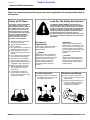
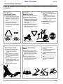
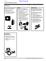
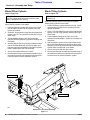
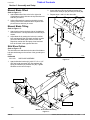
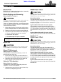
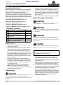
Table of Contents
Rear Blade
RB4596, RB45108 & RB5596
Model RB45
Model RB55
10347
10351
301-133M
Operator’s Manual
!
Read the Operator’s manual entirely. When
you see this symbol, the subsequent
instructions and warnings are serious - follow
without exception. Your life and the lives of
others depend on it!
© Copyright 2007 Printed
5/21/07
Cover photo may show optional equipment
not supplied with standard unit.
Land Pride
Table of Contents
Table of Contents
Important Safety Information . . . . . . . . . . .1
Section 3: Operating Procedures . . . . . .11
Safety at All Times . . . . . . . . . . . . . . . . . . . . . . . . . 1
Look For The Safety Alert Symbol . . . . . . . . . . . . . 1
Safety Labels . . . . . . . . . . . . . . . . . . . . . . . . . . . . . 4
Operating Check List . . . . . . . . . . . . . . . . . . . . . . 11
Transporting . . . . . . . . . . . . . . . . . . . . . . . . . . . . . 11
Basic Operating Instructions . . . . . . . . . . . . . . . . 11
General Operating Instructions . . . . . . . . . . . . . . 12
Introduction . . . . . . . . . . . . . . . . . . . . . . . .5
Application . . . . . . . . . . . . . . . . . . . . . . . . . . . . . . . 5
Using This Manual . . . . . . . . . . . . . . . . . . . . . . . . . 5
Owner Assistance . . . . . . . . . . . . . . . . . . . . . . . . . 5
Section 4: Options . . . . . . . . . . . . . . . . . .13
Section 1: Assembly and Setup . . . . . . . .6
Maintenance . . . . . . . . . . . . . . . . . . . . . . . . . . . . 14
Lubrication . . . . . . . . . . . . . . . . . . . . . . . . . . . . . . 14
Moldboard and Blade . . . . . . . . . . . . . . . . . . . 14
Pivot Shaft . . . . . . . . . . . . . . . . . . . . . . . . . . . . 14
RB45 & RB55 Rear Blade . . . . . . . . . . . . . . . . . . . 6
Tractor Hook-Up . . . . . . . . . . . . . . . . . . . . . . . . . . 7
RB55 3-Point Hitch Settings . . . . . . . . . . . . . . . . . 7
Category ll Standard Hitch: . . . . . . . . . . . . . . . . 7
Category ll Quick Hitch: . . . . . . . . . . . . . . . . . . . 7
Category lll Standard Hitch: . . . . . . . . . . . . . . . 7
Blade Offset Cylinder . . . . . . . . . . . . . . . . . . . . . . . 8
Blade Tilting Cylinder . . . . . . . . . . . . . . . . . . . . . . . 8
Manual Blade Offset . . . . . . . . . . . . . . . . . . . . . . . 9
Manual Blade Tilting . . . . . . . . . . . . . . . . . . . . . . . 9
Skid Shoe Option . . . . . . . . . . . . . . . . . . . . . . . . . . 9
Skid Shoes . . . . . . . . . . . . . . . . . . . . . . . . . . . . . . 13
Section 5: Maintenance and Lubrication 14
Section 6: Specifications & Capacities . .15
Section 7: Features and Benefits . . . . . .16
Section 8: Appendix . . . . . . . . . . . . . . . . .18
Torque Values Chart . . . . . . . . . . . . . . . . . . . . . . 18
Warranty . . . . . . . . . . . . . . . . . . . . . . . . . . . . . . . 19
Section 2: Adjustments . . . . . . . . . . . . . .10
Blade Pitch . . . . . . . . . . . . . . . . . . . . . . . . . . . . . 10
Blade Angling and Reversing . . . . . . . . . . . . . . . . 10
Blade Tilt . . . . . . . . . . . . . . . . . . . . . . . . . . . . . . . 10
Manual Tilt Adjustment . . . . . . . . . . . . . . . . . . 10
Hydraulic Tilt Adjustment . . . . . . . . . . . . . . . . 10
RB45 Blade Offset . . . . . . . . . . . . . . . . . . . . . . . . 10
Manual Blade Offset . . . . . . . . . . . . . . . . . . . . 10
Hydraulic blade Offset with 16” stroke cylinder 10
Hydraulic blade Offset with 14” stroke cylinder 10
RB55 Blade Offset . . . . . . . . . . . . . . . . . . . . . . . . 10
Manual Blade Offset . . . . . . . . . . . . . . . . . . . . 10
Hydraulic blade Offset with 16” stroke cylinder 10
Hydraulic blade Offset with 14” stroke cylinder 10
© Copyright 2007 All rights Reserved
Land Pride provides this publication “as is” without warranty of any kind, either expressed or implied. While every precaution has been taken in the preparation of this manual, Land
Pride assumes no responsibility for errors or omissions. Neither is any liability assumed for damages resulting from the use of the information contained herein. Land Pride reserves
the right to revise and improve its products as it sees fit. This publication describes the state of this product at the time of its publication, and may not reflect the product in the future.
Land Pride is a registered trademark.
All other brands and product names are trademarks or registered trademarks of their respective holders.
Printed in the United States of America.
RB4596, RB45108 & RB5596 Rear Blade 301-133M
5/21/07
Land Pride
▲
Table of Contents
Important Safety Information
Important Safety Information
These are common practices that may or may not be applicable to the products described in
this manual.
Safety at All Times
Look For The Safety Alert Symbol
Thoroughly read and understand
the instructions given in this
manual before operation. Refer to
the “Safety Label” section, read
all instructions noted on them.
Do not allow anyone to operate
this equipment who has not fully
read and comprehended this
manual and who has not been
properly trained in the safe
operation of the equipment.
The SAFETY ALERT SYMBOL indicates there is a
potential hazard to personal safety involved and extra
safety precaution must be taken. When you see this
symbol, be alert and carefully read the message that
follows it. In addition to design and configuration of
equipment, hazard control and accident prevention
are dependent upon the awareness, concern,
prudence and proper training of personnel involved in
the operation, transport, maintenance and storage of
equipment.
▲ Operator should be familiar with
all functions of the unit.
▲ Operate implement from the
driver’s seat only.
▲ Do not leave tractor or implement
unattended with engine running.
▲ Dismounting from a moving
tractor could cause serious injury
or death.
▲ Do not stand between the tractor
and implement during hitching.
▲ Keep hands, feet, and clothing
away from power-driven parts.
▲ Wear snug fitting clothing to avoid
entanglement with moving parts.
▲ Watch out for wires, trees, etc.,
when raising implement. Make
sure all persons are clear of
working area.
▲ Turning tractor too tight may
cause implement to ride up on
wheels. This could result in injury
or equipment damage.
!
Be Aware of
Signal Words
! WARNING
A Signal word designates a degree or
level of hazard seriousness. The
signal words are:
! DANGER
Indicates an imminently hazardous
situation which, if not avoided, will
result in death or serious injury. This
signal word is limited to the most
extreme situations, typically for
machine components that, for
functional purposes, cannot be
guarded.
Indicates a potentially hazardous
situation which, if not avoided, could
result in death or serious injury, and
includes hazards that are exposed
when guards are removed. It may also
be used to alert against unsafe
practices.
! CAUTION
Indicates a potentially hazardous
situation which, if not avoided, may
result in minor or moderate injury. It
may also be used to alert against
unsafe practices.
For Your Protection
Shutdown and Storage
▲ Thoroughly read and understand
the “Safety Label” section, read all
instructions noted on them.
▲ Lower machine to ground, put
tractor in park, turn off engine, and
remove the key.
▲ Detach and store implements in a
area where children normally do
not play. Secure implement by
using blocks and supports.
OFF
REMO
VE
5/21/07
RB4596, RB45108 & RB5596 Rear Blade 301-133M
1
Table of Contents
Land Pride
Important Safety Information
These are common practices that may or may not be applicable to the products described in
this manual.
Use Safety
Lights and Devices
Transport
Machinery Safely
▲ Slow moving tractors, selfpropelled equipment, and towed
implements can create a hazard
when driven on public roads. They
are difficult to see, especially at
night.
▲ Flashing warning lights and turn
signals are recommended
whenever driving on public roads.
Use lights and devices provided
with implement.
▲ Comply with state and local laws.
▲ Maximum transport speed for
implement is 20 mph. DO NOT
EXCEED. Never travel at a speed
which does not allow adequate
control of steering and stopping.
Some rough terrain require a
slower speed.
▲ Sudden braking can cause a
towed load to swerve and upset.
Reduce speed if towed load is not
equipped with brakes.
Use A Safety Chain
▲ A safety chain will help control
drawn machinery should it
separate from the tractor
drawbar.
▲ Use a chain with the strength
rating equal to or greater than
the gross weight of the towed
machinery.
▲ Attach the chain to the tractor
drawbar support or other
specified anchor location. Allow
only enough slack in the chain to
permit turning.
▲ Do not use safety chain for
towing.
2
Practice Safe Maintenance
▲ Understand procedure before
doing work. Use proper tools and
equipment, refer to Operator’s
Manual for additional information.
▲ Work in a clean dry area.
▲ Lower the implement to the
ground, put tractor in park, turn off
engine, and remove key before
performing maintenance.
RB4596, RB45108 & RB5596 Rear Blade 301-133M
▲ Use the following maximum
speed - tow load weight ratios as
a guideline:
20 mph when weight is less
than or equal to the weight of
tractor.
10 mph when weight is double
the weight of tractor.
▲ IMPORTANT: Do not tow a load
that is more than double the
weight of tractor.
▲ Allow implement to cool
completely.
▲ Do not grease or oil implement
while it is in operation.
▲ Inspect all parts. Make sure parts
are in good condition & installed
properly.
▲ Remove buildup of grease, oil or
debris.
▲ Remove all tools and unused
parts from implement before
operation.
5/21/07
Table of Contents
Land Pride
Important Safety Information
These are common practices that may or may not be applicable to the products described in
this manual.
Prepare for Emergencies
▲ Be prepared if a fire starts.
▲ Keep a first aid kit and fire
extinguisher handy.
▲ Keep emergency numbers for
doctor, ambulance, hospital and
fire department near phone.
Wear
Protective Equipment
Avoid High
Pressure Fluids Hazard
▲ Protective clothing and equipment
should be worn.
▲ Wear clothing and equipment
appropriate for the job. Avoid
loose fitting clothing.
▲ Prolonged exposure to loud noise
can cause hearing impairment or
hearing loss. Wear suitable
hearing protection such as
earmuffs or earplugs.
▲ Operating equipment safely
requires the full attention of the
operator. Avoid wearing radio
headphones while operating
machinery.
▲ Escaping fluid under pressure can
penetrate the skin causing serious
injury.
▲ Avoid the hazard by relieving
pressure before disconnecting
hydraulic lines.
▲ Use a piece of paper or
cardboard, NOT BODY PARTS, to
check for suspected leaks.
▲ Wear protective gloves and safety
glasses or goggles when working
with hydraulic systems.
▲ If an accident occurs, see a
doctor immediately. Any fluid
injected into the skin must be
treated within a few hours or
gangrene may result.
911
Keep Riders
Off Machinery
▲ Riders obstruct the operator’s
view, they could be struck by
foreign objects or thrown from the
machine.
▲ Never allow children to operate
equipment.
5/21/07
RB4596, RB45108 & RB5596 Rear Blade 301-133M
3
Table of Contents
Land Pride
Important Safety Information
Safety Labels
Your Rear Blade comes equipped with all safety labels in place.
They were designed to help you safely operate your implement.
Read and follow their directions.
1. Keep all safety labels clean and legible.
2. Replace all damaged or missing labels. To order new
labels go to your nearest Land Pride dealer or visit our
dealer locator at landpride.com.
3. Some new equipment installed during repair requires
safety labels to be affixed to the replaced component as
4.
specified by Land Pride. When ordering new components
make sure the correct safety labels are included in the
request.
Refer to this section for proper label placement.
To install new labels:
a. Clean the area the label is to be placed.
b. Spray soapy water on the surface where the label is to
be placed.
c. Peel backing from label. Press firmly onto the surface.
d. Squeeze out air bubbles with the edge of a credit card.
818-202C
15001
Caution: Retaining Nut
818-230C
15014
4
RB4596, RB45108 & RB5596 Rear Blade 301-133M
Red reflector (Both ends)
5/21/07
Land Pride
Table of Contents
Introduction
Introduction
Land Pride welcomes you to the growing family of new
product owners.
This implement has been designed with care and built by
skilled workers using quality materials. Proper assembly,
maintenance, and safe operating practices will help you
get years of satisfactory use from the machine.
Application
Land Pride’s RB45 and RB55 Series Rear Blade is built
tough from the ground up for applications ranging from
landscaping, construction, snow removal, feedlot
cleaning and all-around farm use. Available options
include single hydraulic gauge wheel, side plates for
holding dirt in and skid shoes for blade protection. See
“Section 7: Features and Benefits” on page 16 for
additional information.
Land Pride dealer. A dealer has trained personnel, repair
parts and equipment needed to service the Rear Blade.
The parts on your Rear Blade have been specially
designed and should only be replaced with genuine Land
Pride parts. Therefore, should your Rear Blade require
replacement parts go to your Land Pride Dealer.
Serial Number Plate
For prompt service always use the serial number and
model number when ordering parts from your Land Pride
dealer. Be sure to include your serial and model numbers
in correspondence also. Refer to Figure 1: for the
location of your serial number plate.
Using This Manual
• This Operator’s Manual is designed to help familiarize
•
•
you with safety, assembly, operation, adjustments,
troubleshooting, and maintenance. Read this manual
and follow the recommendations to help ensure safe
and efficient operation.
The information contained within this manual was
current at the time of printing. Some parts may change
slightly to assure you of the best performance.
To order a new Operator’s or Parts Manual contact
your authorized dealer. Manuals can also be
downloaded, free-of-charge from our website at
www.landpride.com or printed from the Land Pride
Service & Support Center by your dealer.
Terminology
“Right” or “Left” as used in this manual is determined by
facing forward in the direction the machine will operate
while in use unless otherwise stated.
Definitions
NOTE: A special point of information that the
operator must be aware of before continuing.
IMPORTANT: A special point of information related
to its preceding topic. Land Pride’s intention is that
this information should be read and noted before
continuing.
Owner Assistance
The Warranty Registration card should be filled out by
the dealer at the time of purchase. This information is
necessary to provide you with quality customer service.
14999
Serial Number Location
Figure 1
Further Assistance
Your dealer wants you to be satisfied with your new Rear
Blade. If for any reason you do not understand any part
of this manual or are not satisfied with the service
received, the following actions are suggested:
1. Discuss the matter with your dealership service
manager making sure he is aware of any problems
you may have and that he has had the opportunity to
assist you.
2. If you are still not satisfied, seek out the owner or
general manager of the dealership, explain the
problem and request assistance.
3. For further assistance write to:
Land Pride Service Department
1525 East North Street
P.O. Box 5060
Salina, Ks. 67402-5060
E-mail address
[email protected]
If customer service or repair parts are required contact a
5/21/07
RB4596, RB45108 & RB5596 Rear Blade 301-133M
5
Table of Contents
Land Pride
Section 1: Assembly and Setup
Section 1: Assembly and Setup
RB45 & RB55 Rear Blade
Refer to Figure 1-1:
1. Uncrate blade Assembly from shipping crate.
2. Remove front hitch assembly (#1) from blade
panel (#2).
3. Use a lifting device to set blade panel (#2) upright.
Remove rotation pin (#3) and position main frame
(#4) at 90˚ to blade panel and replace rotation lock
pin (#3).
4. Remove pin (#5) and rotate support stand (#6) to a
vertical position. Reinsert pin (#5) and secure with
lock pin.
5. Lower unit to ground and unhook lifting device.
6. Remove front pivot shaft (#7) from front hitch
assembly (#1) by removing #8, 9 & 10 hardware.
7. Secure front hitch assembly (#1) to a lifting device or
attach to a tractor. See “Tractor Hook-Up” on page 7.
8. Position front hitch to main frame as shown. (Bottom
plate of main frame (#4) sets on top of front hitch
tubing cross member (#1).) Align holes and install
front pivot shaft (#7). When top plate of pivot shaft
bottoms out on top plate of front hitch, reinstall (# 8,
9 & 10). Tighten hardware to secure front pivot
shaft (#7).
9. If not already done, attach unit to tractor 3-point
hitch. Top 3-point pin and lynch pin to be supplied by
customer.
10. Check to be sure castle nut (#11) and pivot
washer (#12) are securely attached to threaded tilt
shaft. Raise blade with tractor 3-point. Support main
frame section with blade approximately 1" to 2" off
the ground.
RB45 & RB55 Rear Blade Assembly
Figure 1-1
6
RB4596, RB45108 & RB5596 Rear Blade 301-133M
11. Remove rotation lock pin (#3). Rotate blade panel
(#2). If panel rotates too hard or is too loose, remove
cotter pin (#13). Tighten or loosen castle nut (#11) to
adjust pivoting movement to desired tension.
Reinstall cotter pin (#13) bending both legs around
castle nut.
IMPORTANT: Retighten castle nut (#11) after first
20 hours of use and check periodically.
!
CAUTION
Always check to be sure that the slotted hex nut and cotter pin are
in place to retain the blade before reversing the blade. If they are
missing, the blade will fall off the frame while being rotated!
10349
5/21/07
Table of Contents
Land Pride
Section 1: Assembly and Setup
Tractor Hook-Up
RB55 3-Point Hitch Settings
Refer to Figures 1-2, 1-3, 1-4 & 1-5:
Category ll Standard Hitch:
Refer to Figure 1-3:
Hitch pins (#2) are inserted from the outer lug. Place
spacer adapter (#1) on hitch pin (#2) outside of the inner
most lug and secured with lock pin (#3).
!
DANGER
Tractor hook-up to equipment is dangerous and can result in
serious injury or death. Do not allow anyone to stand between
the blade and tractor during hook-up operations. Do not
operate the hydraulic 3-point lift controls while someone is
directly behind the tractor or near the blade.
1. Slowly back tractor up to the Rear Blade while using
tractor’s 3-point hydraulic control to align the lower
hitch link holes with lower hitch clevis holes on the
blade.
2. Engage park brake, shut engine off and remove key
before dismounting from tractor.
a. With tractor’s lower hitch arms aligned and positioned
in the clevises, insert hitch pins through the clevis lugs
and lower arm holes. Be sure to use the bushings as
shown in Figures 1-3, 1-4 & 1-5. Secure hitch pins with
linch pins.
3. Connect top center link to the upper pivot hitch
mounting holes using customer supplied clevis pin
and linch pin.
4. Ensure that the lower hitch arms are blocked to
prevent excessive side movement.
5. Remove hitch pin and raise support stand fully up.
Reinsert hitch pin and secure with lock pin.
6. Return to tractor and slowly operate controls up and
down to check for clearance. Make certain the
blade does not interfere with the tractor hitch, tires,
and drawbar. Move or remove the drawbar if it
interferes.
7. Manually adjust one of the two lower lift arms up or
down to level the blade from left to right.
8. Manually adjust length of the top-link to level the
blade from front to rear.
11922
Category ll Standard Hitch
Figure 1-3
Category ll Quick Hitch:
Refer to Figure 1-4:
Bushings (#2) are positioned next to the outer most hitch
lug with hitch pins (#3) inserted from the inner most lug.
Place spacer adapter (#1) on hitch pin (#3) outside of the
outer most lug and secured with the lock pin (#4).
11921
Category ll Quick Hitch
Figure 1-4
Category lll Standard Hitch:
Refer to Figure 1-5:
Bushings (#2) are positioned next to the inner most hitch
lug with hitch pins (#3) inserted from the outer most lug.
Place spacer adapter (#1) on hitch pin (#3) outside of the
inner most lug and secured with the lock pin (#4).
10355
23998
Tractor 3-Point Hitch
Figure 1-2
5/21/07
Category lll Standard Hitch
Figure 1-5
RB4596, RB45108 & RB5596 Rear Blade 301-133M
7
Table of Contents
Land Pride
Section 1: Assembly and Setup
Blade Offset Cylinder
Blade Tilting Cylinder
Refer to Figure 1-6:
Refer to Figure 1-6:
IMPORTANT: Attach cylinder base to the front hitch
lug. The cylinder base will interfere with the main
frame if attached to the rear lug.
Assemble hydraulic hoses to the hydraulic cylinder
before placing cylinder on the blade.
1. Position hydraulic cylinder with ports on top. Install
two 90 degree elbows into the cylinder ports and
tighten as needed.
2. Screw 96" long hydraulic hoses into the elbows and
tighten. Use 101” long hydraulic hoses when sing a
Quick Hitch.
3. Thread adapter fittings to the other end of the
hydraulic hoses and tighten. (Hydraulic couplings not
furnished.)
4. Attach hydraulic cylinder to the lugs located on either
side of the Rear Blade with clevis pins. Make sure
hydraulic ports are positioned on top and the cylinder
base in positioned to the front as shown.
5. Secure clevis pins with hair pin cotters.
6. Route hoses through hose brackets located on top of
the main frame and on the right side of the front hitch.
Connect hoses to tractor's hydraulic system.
IMPORTANT: Attach cylinder base to the upper
mounting lug.
Assemble hydraulic hoses to the hydraulic cylinder
before placing cylinder on the blade.
1. Position hydraulic cylinder with ports on top. Install
two 90 degree elbows into the cylinder ports and
tighten as needed.
2. Screw 114" long hydraulic hoses into the elbows and
tighten. Use 125” long hydraulic hoses when sing a
Quick Hitch.
3. Thread adapter fittings to the other end of the
hydraulic hoses and tighten. (Hydraulic couplings not
furnished.)
4. Attach hydraulic cylinder to the lugs located on the
back of the Rear Blade with clevis pins. Make sure
hydraulic ports are positioned facing forward and the
cylinder base in positioned up as shown.
5. Secure clevis pins with hair pin cotters.
6. Route hoses through hose brackets located on top of
the main frame and on the right side of the front hitch.
Connect hoses to tractor's hydraulic system.
Blade Tilting
Blade Angling
15004
Hydraulic Tilt and Offset Assembly
Figure 1-6
8
RB4596, RB45108 & RB5596 Rear Blade 301-133M
5/21/07
Table of Contents
Land Pride
Section 1: Assembly and Setup
Manual Blade Offset
Refer to Figure 1-7:
1. Attach blade offset links to the left or right side
of the blade as shown with two clevis pins and secure
with hair pin cotters.
2. Adjust offset angle by removing the hitch pin and
moving outer link to a different hole. Replace hitch
pin and secure with hair pin cotter.
2. Insert skid shoe (#2) into skid shoe bracket (#1).
Secure with clevis pin (#3) and hair pin cotter (#4).
3. Repeat steps 1 and 2 for the other side.
Manual Blade Tilting
Refer to Figure 1-7:
1. Attach ratchet jack to the back side of the blade as
shown with two 1" clevis pins and secure with hair pin
cotters.
2. Adjust blade tilt by setting the lock on the ratchet
lever and pumping the lever back and forth to raise
one end of the blade higher than the other end.
Reposition ratchet lock and pump lever back and
forth to tilt blade in the opposite direction.
Skid Shoe Option
Refer to Figure 1-8:
The skid shoes are attached to both ends of the blade to
help prevent damage to the surface of the ground by the
blade.
Kit Bundle
301-110A
10350
Skid Shoe Assembly
Figure 1-8
SKID SHOE ASSEMBLY
1. Attach skid shoe bracket (#1) with 1/2"-13 x 4 1/2"
GR5 hex head cap screw (#5), flat washers (#6),
spring lock washer (#7) and hex nut (#8). Tighten
hardware to the correct torque.
Blade Tilting
Blade Angling
15003
Manual Tilt and Offset Assembly
Figure 1-7
5/21/07
RB4596, RB45108 & RB5596 Rear Blade 301-133M
9
Table of Contents
Land Pride
Section 2: Adjustments
Section 2: Adjustments
Blade Pitch
Blade pitch can be adjusted by lengthening or shortening
the tractor’s top center 3-point link.
Blade Angling and Reversing
Refer to Figure 1-7 on page 9:
!
CAUTION
Avoid injury from falling blade by always check to make sure
all hardware is secured properly before rotating blade.
There are 7 blade angle positions; up to 45 degrees right
or left 15 degree increments. (Center, 3 clockwise and 3
counterclockwise positions.)
1. Adjust blade angle by removing the angling locking
pin and rotating the blade to a different hole position.
2. Replace angle locking pin and secure with hair pin.
3. The blade may also be rotated around 180 degrees.
a. Remove angling locking pin from turntable.
b. Rotate blade 180 degrees.
c. Reconnect angle locking pin to turntable.
IMPORTANT: Make sure the angling link is properly
re-installed before using the blade.
Blade Tilt
!
CAUTION
Avoid injury from falling blade by always checking to make
sure all hardware is secured properly before tilting blade.
Manual Tilt Adjustment
Refer to Figure 1-7 on page 9:
The blade end can be tilted manually by as much 20
degrees with the ratchet jack.
1. Set ratchet lock and pump lever back and forth to
raise one end of the blade higher than the other end.
2. Reposition ratchet lock and pump lever back and
forth to tilt blade in the opposite direction.
Hydraulic Tilt Adjustment
Refer to Figure 1-6 on page 8:
The blade end can be tilted hydraulically with the tilt
cylinder by as much as 20 degrees.
RB45 Blade Offset
!
CAUTION
The blade may come in contact with the tractor rear tire when
offsetting blade to maximum position and angling blade in the
same direction to most severe angle.
Manual Blade Offset
The blade will offset to the right if the manual link is
mounted on the left side and to the left if it is mounted on
the right side. There are 5 offset positions; centered; 4”,
10 1/2”, 17” and 23”.
Hydraulic blade Offset with 16” stroke cylinder
If the cylinder is mounted on the right hand side, the
blade will offset to the left up to 27” and to the right up to
10”. If the cylinder is mounted on the left hand side, the
blade will offset to the right up to 27” and to the left up to
10”.
Hydraulic blade Offset with 14” stroke cylinder
If the cylinder is mounted on either side it will offset both
directions 13 1/2”.
RB55 Blade Offset
!
CAUTION
The blade may come in contact with the tractor rear tire when
offsetting blade to maximum position and angling blade in the
same direction to most severe angle.
Manual Blade Offset
The blade will offset to the right if the manual link is
mounted on the left side and to the left if it is mounted on
the right side. There are 5 offset positions; centered;
offset 6 1/2”, 13”, 19 1/2” and 25 1/2”.
Hydraulic blade Offset with 16” stroke cylinder
If the cylinder is mounted on the right hand side, the
blade will offset to the left up to 29 1/2” and to the right up
to 12 1/2”. If the cylinder is mounted on the left hand side,
the blade will offset to the right up to 29 1/2” and to the left
up to 12 1/2”.
Hydraulic blade Offset with 14” stroke cylinder
If the cylinder is mounted on either side it will offset both
directions 16”.
1. Operate tractor control lever to change blade tilt by
as much as 20 degrees right or left.
10
RB4596, RB45108 & RB5596 Rear Blade 301-133M
5/21/07
Land Pride
Table of Contents
Section 3: Operating Procedures
Section 3: Operating Procedures
Operating Check List
Hazard control and accident prevention are dependent
upon the awareness, concern, prudence and proper
training involved in the operation, transport,
maintenance and storage of the blade. Therefore, it is
absolutely essential that no one operates the Rear Blade
without first having read, fully understood and become
totally familiar with the Operator’s Manual. Make sure the
operator has paid particular attention to:
• Important Safety Information, pages 1 to 3
• Section 1: Assembly and Setup, page 6
• Section 2: Adjustments, page 10
• Section 3: Operating Procedures, page 11
• Section 5: Maintenance and Lubrication, page 14
Operating Checklist
✔ Check
Check 3-point Hook-up procedure. Be sure all
pins have been installed and are secured.
Reference
Page 7
All blade adjustments have been made and pins
have been installed and are secured.
Page 7
The operator has read and understood how to
operate the blade.
Page 11
The Rear Blade has been lubricated as required.
Page 14
Check the blade initially and periodically for loose
bolts & pins, See Torque Values Chart.
Page 18
Make the following inspections after attaching the Rear
Blade to the tractor:
1. Inspect tractor safety equipment to make sure it is in
good working condition.
2. Carefully raise and lower the implement to ensure
that the drawbar, tires, and other equipment on the
tractor do not contact the frame and moldboard.
3. Carefully pivot blade fully clockwise and offset blade
such that the moldboard end closest to the tractor is
in line with the tractor tire. Raise and lower
implement to ensure tractor tires and tractor do not
contact the blade.
4. Carefully pivot blade fully counterclockwise and
offset blade such that the moldboard end closest to
the tractor is in line with the tractor tire. Raise and
lower implement to ensure tractor tires and tractor do
not contact the blade.
5. Inspect hydraulic hoses for wear, damage and
hydraulic leaks. See “Avoid High Pressure Fluids
Hazard” on page 3. Replace damaged and worn hoses
with genuine Land Pride parts.
Transporting
!
CAUTION
When traveling on public roads at night or during the day, use
accessory lights and devices for adequate warning to
operators of other vehicles. Comply with all federal, state and
local laws.
5/21/07
1. When traveling on roadways, transport in such a way
that faster moving vehicles may pass you safely.
2. Leave enough clearance on both sides of the blade
when traveling straight or making turns to keep the
blade from contacting obstacles such as buildings,
trees or fences.
3. Slow down when traveling over rough or hilly terrain.
Basic Operating Instructions
!
WARNING
Do not use blade tilt to raise tractor tires off the ground for
repair. Improper use can damaged the Rear Blade.
!
WARNING
Do not operate the side shift cylinder with blade in the ground
or to push or pull other objects. Improper use can damaged
the Rear Blade.
!
WARNING
Do not use the blade for pulling fence posts, stumps, etc.,
lifting objects, carry objects or towing other equipment. Any
of the above can result in Rear Blade damage, serious bodily
injury or death.
!
DANGER
Never carry a person on the blade. A person can fall and be
ran over by the blade or tractor causing serious injury or
death.
IMPORTANT: Avoid catching the hydraulic hoses on
brush, post, stumps, and other protrusions that
could damage and/or break them.
1. Thoroughly inspect the work area for buried utility
cables, pipelines, sprinkler heads and any
unforeseen objects. Mark any potential hazards.
2. Place grade stakes if you intend to develop a specific
grade or soil level.
3. Adjust the blade to the desired angle, tilt, and offset
position before lowering the blade to the ground.
4. Lower blade to the ground and proceed forward at a
speed of no more than 2 to 4 mph. The blade should
immediately begin shaving the soil surface.
5. Set the tractor’s draft-link height control to the
desired position. With the blade set at a 90 degree
angle you may need to raise the blade slightly so that
the dirt or gravel can flow out evenly under the blade
effectively shaving off high spots and filling in
potholes or depressions.
RB4596, RB45108 & RB5596 Rear Blade 301-133M
11
Table of Contents
Land Pride
Section 3: Operating Procedures
General Operating Instructions
Once you have familiarized yourself with the Operator’s
Manual, completed the operations checklist, and
properly attached your Land Pride blade to your tractor,
you are now almost ready to begin work. The RB45 and
RB55 Series blades were designed and built by Land
Pride for category lI and lII three-point hitch and Quick
Hitch attachment for 70 to 110 hp tractors with the RB45
Series and 90 to 180 hp tractors with the RB55 Series
that are equipped with remote hydraulic outlets and two
wheel drive capability. They are ideal for snow removal
as well as dirt leveling, finish grading, and backfilling
applications at feedlots, outdoor arenas, building and
construction sites, and maintenance operations on farm
and ranch lanes or roadways. They are also excellent for
soil contouring and construction and maintenance of
ditches and waterways.
Hopefully you have checked out your work site for any
buried utility cables, pipelines, sprinkler heads, or other
obstacles that you wouldn’t want to damage or
encounter. Grade stakes should now be in place if you
intend to develop a specific grade, elevation, soil
contour, or roadbed crown. The blade’s primary purpose
is for grading or leveling of soil, gravel, or aggregate in
the warmer months or snow removal in the colder
months. These functions are best done at an
approximate 2 to 4 mph ground speed. Becoming
proficient with a blade takes practice.
easily performed by reversing the blade and operating
the tractor in reverse or commonly called the push mode.
If you are performing the construction of soil contours or
waterways you will probably need to set a tilt angle on the
blade to achieve the desired effect. If you are grading or
cutting a new ditch bank or forming a road crown, you will
probably want to offset the blade in combination with
setting an appropriate tilt angle. This again will likely
require some experimentation to gain desired results.
Snow removal techniques with a blade will be very
similar to dirt working techniques and will require a little
experimentation to become proficient.
With a little practice you should become a very good
operator and consistently achieve the desired results
you expect with your Land Pride RB45 and RB55 Series
blade.
See “Section 6: Specifications & Capacities” on page 15
and “Section 7: Features and Benefits” on page 16 for
additional information and performance enhancing
options.
Tractor horsepower, your personal skill level, soil or
aggregate composition, moisture levels, and compaction
factors will all have a definite impact on how easily and
effectively you get the job done when you are in the dirt
working mode. Develop a plan to achieve your expected
results. Set the blade up at the proper angle or angles to
do the job. The hydraulic tilt, and offset capabilities of the
RB45 and RB55 series make these adjustments easy
utilizing the tractors remote hydraulic controls. Adjust the
blade angle by simply pulling a pin and rotating the blade
to the desired angle and reinserting the pin. Setting the
blade up may require some experimentation to achieve
the desired results. Lower the blade to the ground and
proceed forward at a speed of no more than 2 to 4 mph.
The blade should immediately begin shaving the soil
surface and dirt or aggregate material. Set the tractor’s
draft-link height control in the desired position. With the
blade set at a 90 degree angle you may need to raise the
blade slightly so that the dirt or gravel can flow out evenly
under the blade effectively shaving off high spots and
filling in potholes or depressions.
If you have the blade set at a horizontal angle, the
shaved or accumulated material will begin to move
outward toward the trailing edge of the blade. The
greater the angle the more quickly the shaved material
will be distributed off to the side. If it is necessary to work
up next to a building foundation, abutment, or raised curb
you may want to offset the blade so that the outside edge
of the blade is beyond the outer edge of the tractor tire in
working position. Back-filling operations may be more
12
RB4596, RB45108 & RB5596 Rear Blade 301-133M
5/21/07
Land Pride
Table of Contents
Section 4: Options
Section 4: Options
Skid Shoes
The skid shoes are attached to both ends of the blade to
help prevent damage to the surface of the ground by the
blade. Refer to the skid shoe manual for assembly
instructions and operations.
Kit Bundle
301-110A
SKID SHOE ASSEMBLY
15002
5/21/07
RB4596, RB45108 & RB5596 Rear Blade 301-133M
13
Table of Contents
Land Pride
Section 5: Maintenance and Lubrication
Section 5: Maintenance and Lubrication
Maintenance
Proper servicing and adjustment is the key to the long life
of any implement. With careful and systematic
inspection, you can avoid costly maintenance, time and
repair.
After using your Rear Blade for several hours, check all
bolts to be sure they are tight.
!
WARNING
Do not alter the Rear Blade. Altering the blade can adversely
affect its performance and reliability causing damage to the
blade, tractor and/or bodily injury. Always replace damaged
parts with original Land Pride parts.
Replace any worn, damaged or illegible safety labels by
obtaining new labels from your Land Pride Dealer
Lubrication
Lubrication
Legend
Multi-purpose
spray lube
Multi-purpose
grease lube
Multi-purpose
oil lube
50
hrs
Intervals in hours at which
lubrication is required
Seasonally
Moldboard and Blade
Grease moldboard and blade when storing for an extended
period of time.
Type of Lubrication: Multi-Purpose
10347
Quantity = Coat Generously
25
Hours
Pivot Shaft
Grease every 24 hours.
Type of Lubrication: Multi-Purpose
15000
14
RB4596, RB45108 & RB5596 Rear Blade 301-133M
Quantity = 2-4 pumps
5/21/07
Table of Contents
Land Pride
Section 6: Specifications & Capacities
Section 6: Specifications & Capacities
RB45 & RB55 Series Rear Blades
Model/Series
Blade Width
Approximate Weight (lbs.)
Max. Gross Vehicle Weight (G.V.W.)
Horsepower Rating
Hitch Type
Blade Thickness
Blade Height
Angle/Position
Cutting Edge
Tilt
Options
Blade Construction
RB4596
RB45108
RB5596
96”
108”
96”
890 *
940 *
1330 *
9,500 lbs.
15,000 lbs.
9,500 lbs.
90
180
Cat. 2
Cat. 2 & 3
Fits Land Pride Quick Hitch
1/4” reinforced
5/16” reinforced
19”
6 Forward up to 45 degrees right or left
6 Reverse up to 45 degrees right or left
1/2” x 6”
Reversible
Double bevel
Up to 20 degrees left or right
Skid Shoes
Hydraulic Offset
Hydraulic Tilt
Boxed Section
* No offsetting or tilt components.
5/21/07
RB4596, RB45108 & RB5596 Rear Blade 301-133M
15
Table of Contents
Land Pride
Section 7: Features and Benefits
Section 7: Features and Benefits
RB45 Series Rear Blade
Features
Benefits
Working widths
96”, 108”
HP Range
70 - 110 HP
7 Forward and 7 reverse
positions
Various positions to work in various conditions to get desired results.
Tilt left or right
Tilt moldboard left or right for ditching.
Offset left or right
Position the moldboard beyond tractor tire and enable to work closer to obstructions.
Rolled moldboards
Material ‘rolls’ which causes less drag on the blade.
19” Moldboard height
Tall moldboard allows for a great deal of material to be moved.
Formed moldboard lip
Top lip of moldboard is formed at 90 degrees for additional strength.
” Moldboard thickness with
3/16” reinforcement channel
Heavy-duty moldboard to handle the workload from tractors up to 110 HP.
2 ” Kingpin
Kingpin is matched to handle workloads up to 110 HP.
Reversible cutting edge
Lengthens blade life by being able to use both edges.
Fully welded main frame
Overall mainframe strength is enhanced due to being fully welded.
Retractable parking stand
Enables one person hook-up and keeps the mainframe off the ground.
Heavy-duty pivot housing
5/8” Thick steel gives pivot housing strength, which is very important when pulling blade in
tilt, offset or angled positions.
Optional hydraulic
adjustments
Hydraulic adjustments can be made from the tractor seat for on the go changes.
Warranty
One year parts & labor.
16
RB4596, RB45108 & RB5596 Rear Blade 301-133M
5/21/07
Table of Contents
Land Pride
Section 7: Features and Benefits
RB55 Series Rear Blades
Features
Benefits
Working widths
108”, 120”
Tractor HP Range
90-180 HP
Cat. 2 and 3
Bushing provided to go from Cat. 2 to Cat. 3 enables a wider variety of tractors to be used.
7 Forward and 7 reverse
positions
Various positions to work in various conditions to get desired results.
Tilt left or right
Tilt moldboard left or right for ditching.
Offset left or right
Position the moldboard beyond the tractor tire and enable to work closer to obstructions.
19” Moldboard height
Tall moldboard allows for a great deal of material to be moved.
4” Solid Kingpin
4” Solid steel is matched for workloads up to 180 HP.
Heavy-duty pivot housing
1” Thick steel gives pivot housing strength, which is very important when pulling blade in
tilt, offset or angled positions.
5/16” Moldboard with
reinforcement
Heavy-duty moldboard to handle loads from 180 HP tractors.
Formed moldboard lip
Top lip of moldboard is formed at 90 degrees for additional strength.
Reversible cutting edge
Lengthens blade life by being able to use both edges.
Fully welded reinforced main
frame
Overall mainframe strength is enhanced due to being fully welded.
Retractable parking stand
Enables one person hook-up and keeps the mainframe off of the ground.
Grease points in front pivot
shaft
Helps front pivot shaft to easily move.
Skid shoes (optional)
Skid shoes protect the moldboard from hitting low lying obstructions like manhole covers.
Side plates (optional)
Side plates allow the blade to hold material in to drag from one spot to another.
Hydraulic adjustments
Hydraulic adjustments can be made from the tractor seat for on the go changes.
Warranty
One year parts & labor.
5/21/07
RB4596, RB45108 & RB5596 Rear Blade 301-133M
17
Table of Contents
Land Pride
Section 8: Appendix
Section 8: Appendix
Torque Values Chart
Bolt Head Identification
Bolt Size
(Inches)
in-tpi 1
1/4" - 20
1/4" - 28
5/16" - 18
5/16" - 24
3/8" - 16
3/8" - 24
Grade 2
Grade 5
N · m ft-lb 3 N · m
7.4
8.5
15
17
27
31
5.6
6
11
13
20
22
11
13
24
26
42
47
ft-lb
8
10
17
19
31
35
Bolt Head Identification
Grade 8
N·m
16
18
33
37
59
67
ft-lb
12
14
25
27
44
49
Class 5.8
mm x pitch N · m
M 5 X 0.8
M6X1
M 8 X 1.25
M8X1
M10 X 1.5
M10 X 0.75
8.8
5.8
Bolt Size
(Metric)
4
7
17
18
33
39
ft-lb
3
5
12
13
24
29
10.9
Class 8.8
N·m
6
11
26
28
52
61
ft-lb
5
8
19
21
39
45
Class 10.9
N·m
9
15
36
39
72
85
ft-lb
7
11
27
29
53
62
7/16" - 14
43
32
67
49
95
70
M12 X 1.75
58
42
91
67
125
93
7/16" - 20
49
36
75
55
105
78
M12 X 1.5
60
44
95
70
130
97
1/2" - 13
66
49
105
76
145
105
M12 X 1
90
66
105
77
145
105
1/2" - 20
75
55
115
85
165
120
M14 X 2
92
68
145
105
200
150
9/16" - 12
95
70
150
110
210
155
M14 X 1.5
99
73
155
115
l215
160
9/16" - 18
105
79
165
120
235
170
M16 X 2
145
105
225
165
315
230
5/8" - 11
130
97
205
150
285
210
M16 X 1.5
155
115
240
180
335
245
5/8" - 18
150
110
230
170
325
240
M18 X 2.5
195
145
310
230
405
300
3/4" - 10
235
170
360
265
510
375
M18 X 1.5
220
165
350
260
485
355
3/4" - 16
260
190
405
295
570
420
M20 X 2.5
280
205
440
325
610
450
7/8" - 9
225
165
585
430
820
605
M20 X 1.5
310
230
650
480
900
665
7/8" - 14
250
185
640
475
905
670
M24 X 3
480
355
760
560
1050 780
1" - 8
340
250
875
645
1230 910
M24 X 2
525
390
830
610
1150 845
1" - 12
370
275
955
705
1350 995
M30 X 3.5
960
705
1510 1120 2100 1550
1-1/8" - 7
480
355
1080 795
1750 1290
M30 X 2
1060 785
1680 1240 2320 1710
1 1/8" - 12
540
395
1210 890
1960 1440
M36 X 3.5
1730 1270 2650 1950 3660 2700
1 1/4" - 7
680
500
1520 1120 2460 1820
M36 X 2
1880 1380 2960 2190 4100 3220
1 in-tpi = nominal thread diameter in inches-threads per inch
1 1/4" - 12
750
555
1680 1240 2730 2010
2 N· m = newton-meters
1 3/8" - 6
890
655
1990 1470 3230 2380
3 ft-lb= foot pounds
1 3/8" - 12
1010 745
2270 1670 3680 2710
4 mm x pitch = nominal thread diameter in millimeters x thread
1 1/2" - 6
1180 870
2640 1950 4290 3160
pitch
1 1/2" - 12
1330 980
2970 2190 4820 3560
Torque tolerance + 0%, -15% of torquing values. Unless otherwise specified use torque values listed above.
18
RB4596, RB45108 & RB5596 Rear Blade 301-133M
5/21/07
Warranty
Land Pride warrants to the original purchaser that this Land Pride product will
be free from defects in material and workmanship beginning on the date of
purchase by the end user according to the following schedule when used as
intended and under normal service and conditions for personal use.
Overall Unit: One year Parts and Labor
Hydraulic Cylinder: One year Parts and Labor.
Hoses and Seals: Considered wear items.
Cutting Edges: Considered wear items.
This Warranty is limited to the replacement of any defective part by Land
Pride and the installation by the dealer of any such replacement part, and does
not cover common wear items such as blades, belts, tines, etc. Land Pride
reserves the right to inspect any equipment or parts which are claimed to have
been defective in material or workmanship.
This Warranty does not apply to any part or product which in Land Pride’s
judgment shall have been misused or damaged by accident or lack of normal
maintenance or care, or which has been repaired or altered in a way which
adversely affects its performance or reliability, or which has been used for a
purpose for which the product is not designed. Misuse also specifically includes
failure to properly maintain oil levels, grease points, and driveline shafts.
Claims under this Warranty must be made to the dealer which originally sold
the product and all warranty adjustments must be made through such dealer.
Land Pride reserves the right to make changes in materials or design of the
product at any time without notice.
This Warranty shall not be interpreted to render Land Pride liable for damages
of any kind, direct, consequential, or contingent to property. Furthermore, Land
Pride shall not be liable for damages resulting from any cause beyond its
reasonable control. This Warranty does not extend to loss of crops, any expense
or loss for labor, supplies, rental machinery or for any other reason.
No other warranty of any kind whatsoever, express or implied, is made
with respect to this sale; and all implied warranties of merchantability and
fitness for a particular purpose which exceed the obligations set forth in
this written warranty are hereby disclaimed and excluded from this sale.
This Warranty is not valid unless registered with Land Pride within 30 days
from the date of purchase by the end user.
Corporate Office: P.O. Box 5060
Salina, Kansas 67402-5060 USA
www.landpride.com