1
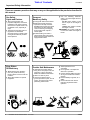
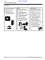
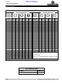
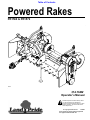
Table of Contents
Powered Rakes
PR1560 & PR1572
18601
314-164M
Operator’s Manual
!
Read the Operator’s manual entirely. When
you see this symbol, the subsequent
instructions and warnings are serious - follow
without exception. Your life and the lives of
others depend on it!
© Copyright 2008 Printed
7/14/08
Cover photo may show optional equipment
not supplied with standard unit.
Land Pride
Table of Contents
Table of Contents
Important Safety Information . . . . . . . . . . .1
Section 4: Maintenance and Lubrication 12
Safety at All Times . . . . . . . . . . . . . . . . . . . . . . . . . 1
Look For The Safety Alert Symbol . . . . . . . . . . . . . 1
Maintenance . . . . . . . . . . . . . . . . . . . . . . . . . . . . 12
Storage . . . . . . . . . . . . . . . . . . . . . . . . . . . . . . . . 12
Drive Chain Maintenance . . . . . . . . . . . . . . . . . . . 12
Chain Case Skid Shoe Replacement . . . . . . . . . . 12
Sprocket & Drive Chain Replacement . . . . . . . . . 12
Lubrication . . . . . . . . . . . . . . . . . . . . . . . . . . . . . . 14
Pivot . . . . . . . . . . . . . . . . . . . . . . . . . . . . . . . . 14
Gauge Wheel Spindle . . . . . . . . . . . . . . . . . . . 14
Gauge Wheel . . . . . . . . . . . . . . . . . . . . . . . . . 14
Drive Chain . . . . . . . . . . . . . . . . . . . . . . . . . . . 15
Non-Drive Bearing . . . . . . . . . . . . . . . . . . . . . . 15
Gearbox . . . . . . . . . . . . . . . . . . . . . . . . . . . . . 15
Introduction . . . . . . . . . . . . . . . . . . . . . . . .8
Application . . . . . . . . . . . . . . . . . . . . . . . . . . . . . . . 8
Using This Manual . . . . . . . . . . . . . . . . . . . . . . . . . 8
Terminology . . . . . . . . . . . . . . . . . . . . . . . . . . . 8
Definitions . . . . . . . . . . . . . . . . . . . . . . . . . . . . . 8
Owner Assistance . . . . . . . . . . . . . . . . . . . . . . . . . 8
Serial Number Plate . . . . . . . . . . . . . . . . . . . . . 8
Further Assistance . . . . . . . . . . . . . . . . . . . . . . 8
Section 1: Assembly and Set-Up . . . . . . . .9
Tractor Requirements . . . . . . . . . . . . . . . . . . . . . . 9
Gauge Wheel Assembly (PR1572) . . . . . . . . . . . . 9
Tractor Hook-Up . . . . . . . . . . . . . . . . . . . . . . . . . . 9
Driveline Installation . . . . . . . . . . . . . . . . . . . . . . . . 9
Section 2: Operating . . . . . . . . . . . . . . . .10
Transporting . . . . . . . . . . . . . . . . . . . . . . . . . . . . 10
Operating Checklist . . . . . . . . . . . . . . . . . . . . . . . 10
Operating Instructions . . . . . . . . . . . . . . . . . . . . . 10
Section 3: Adjustments . . . . . . . . . . . . . .11
Section 5: Specifications & Capacities . .16
Section 6: Features & Benefits . . . . . . . .17
Section 7: Troubleshooting . . . . . . . . . . .18
Section 8: Appendix . . . . . . . . . . . . . . . . .19
Torque Values Chart . . . . . . . . . . . . . . . . . . . . . . 19
Tire Inflation Chart . . . . . . . . . . . . . . . . . . . . . . . . 19
Notes . . . . . . . . . . . . . . . . . . . . . . . . . . . . . . . . . . 20
Limited Warranty . . . . . . . . . . . . . . . . . . . . . . . . . 21
Gauge Wheels . . . . . . . . . . . . . . . . . . . . . . . . . . . 11
Setting the Working Depth . . . . . . . . . . . . . . . . . . 11
Powered Rake Roller . . . . . . . . . . . . . . . . . . . . . . 11
Drive Chain Adjustment . . . . . . . . . . . . . . . . . . . . 11
End Plates . . . . . . . . . . . . . . . . . . . . . . . . . . . . . . 11
Material Control Deflector Adjustment . . . . . . . . . 11
© Copyright 2008 All rights Reserved
Land Pride provides this publication “as is” without warranty of any kind, either expressed or implied. While every precaution has been taken in the preparation of this manual, Land
Pride assumes no responsibility for errors or omissions. Neither is any liability assumed for damages resulting from the use of the information contained herein. Land Pride reserves
the right to revise and improve its products as it sees fit. This publication describes the state of this product at the time of its publication, and may not reflect the product in the future.
Land Pride is a registered trademark.
All other brands and product names are trademarks or registered trademarks of their respective holders.
Printed in the United States of America.
PR1560 & PR1572 Powered Rakes 314-164M
7/14/08
Land Pride
▲
Table of Contents
Important Safety Information
Important Safety Information
These are common practices that may or may not be applicable to the products described in
this manual.
Safety at All Times
Look For The Safety Alert Symbol
Thoroughly read and understand
the instructions given in this
manual before operation. Refer to
the “Safety Label” section, read
all instructions noted on them.
Do not allow anyone to operate
this equipment who has not fully
read and comprehended this
manual and who has not been
properly trained in the safe
operation of the equipment.
The SAFETY ALERT SYMBOL indicates there is a
potential hazard to personal safety involved and extra
safety precaution must be taken. When you see this
symbol, be alert and carefully read the message that
follows it. In addition to design and configuration of
equipment, hazard control and accident prevention
are dependent upon the awareness, concern,
prudence and proper training of personnel involved in
the operation, transport, maintenance and storage of
equipment.
▲ Operator should be familiar with
all functions of the unit.
▲ Operate implement from the
driver’s seat only.
▲ Make sure all guards and shields
are in place and secured before
operating the implement.
▲ Do not leave tractor or implement
unattended with engine running.
▲ Dismounting from a moving
tractor could cause serious injury
or death.
▲ Do not stand between the tractor
and implement during hitching.
▲ Keep hands, feet, and clothing
away from power-driven parts.
▲ Wear snug fitting clothing to avoid
entanglement with moving parts.
▲ Watch out for wires, trees, etc.,
when raising implement. Make
sure all persons are clear of
working area.
▲ Turning tractor too tight may
cause implement to ride up on
wheels. This could result in injury
or equipment damage.
!
Be Aware of
Signal Words
! WARNING
A Signal word designates a degree or
level of hazard seriousness. The
signal words are:
! DANGER
Indicates an imminently hazardous
situation which, if not avoided, will
result in death or serious injury. This
signal word is limited to the most
extreme situations, typically for
machine components that, for
functional purposes, cannot be
guarded.
Indicates a potentially hazardous
situation which, if not avoided, could
result in death or serious injury, and
includes hazards that are exposed
when guards are removed. It may also
be used to alert against unsafe
practices.
! CAUTION
Indicates a potentially hazardous
situation which, if not avoided, may
result in minor or moderate injury. It
may also be used to alert against
unsafe practices.
For Your Protection
Shutdown and Storage
▲ Thoroughly read and understand
the “Safety Label” section, read all
instructions noted on them.
▲ Lower machine to ground, put
tractor in park, turn off engine, and
remove the key.
▲ Detach and store implements in a
area where children normally do
not play. Secure implement by
using blocks and supports.
OFF
REMO
VE
7/14/08
PR1560 & PR1572 Powered Rakes 314-164M
1
Table of Contents
Land Pride
Important Safety Information
These are common practices that may or may not be applicable to the products described in
this manual.
Use Safety
Lights and Devices
Transport
Machinery Safely
▲ Slow moving tractors, selfpropelled equipment, and towed
implements can create a hazard
when driven on public roads. They
are difficult to see, especially at
night.
▲ Flashing warning lights and turn
signals are recommended
whenever driving on public roads.
Use lights and devices provided
with implement.
▲ Comply with state and local laws.
▲ Maximum transport speed for
implement is 20 mph. DO NOT
EXCEED. Never travel at a speed
which does not allow adequate
control of steering and stopping.
Some rough terrain require a
slower speed.
▲ Sudden braking can cause a
towed load to swerve and upset.
Reduce speed if towed load is not
equipped with brakes.
Keep Riders
Off Machinery
Practice Safe Maintenance
▲ Riders obstruct the operator’s
view, they could be struck by
foreign objects or thrown from the
machine.
▲ Never allow children to operate
equipment.
2
▲ Understand procedure before
doing work. Use proper tools and
equipment, refer to Operator’s
Manual for additional information.
▲ Work in a clean dry area.
▲ Lower the implement to the
ground, put tractor in park, turn off
engine, and remove key before
performing maintenance.
PR1560 & PR1572 Powered Rakes 314-164M
▲ Use the following maximum
speed - tow load weight ratios as
a guideline:
20 mph when weight is less
than or equal to the weight of
tractor.
10 mph when weight is double
the weight of tractor.
IMPORTANT: Do not tow a load that
is more than double the weight of
tractor.
▲ Allow implement to cool
completely.
▲ Do not grease or oil implement
while it is in operation.
▲ Inspect all parts. Make sure parts
are in good condition & installed
properly.
▲ Remove buildup of grease, oil or
debris.
▲ Remove all tools and unused
parts from implement before
operation.
7/14/08
Table of Contents
Land Pride
Important Safety Information
These are common practices that may or may not be applicable to the products described in
this manual.
Prepare for Emergencies
▲ Be prepared if a fire starts.
▲ Keep a first aid kit and fire
extinguisher handy.
▲ Keep emergency numbers for
doctor, ambulance, hospital and
fire department near phone.
Wear
Protective Equipment
Avoid High
Pressure Fluids Hazard
▲ Protective clothing and equipment
should be worn.
▲ Wear clothing and equipment
appropriate for the job. Avoid
loose fitting clothing.
▲ Prolonged exposure to loud noise
can cause hearing impairment or
hearing loss. Wear suitable
hearing protection such as
earmuffs or earplugs.
▲ Operating equipment safely
requires the full attention of the
operator. Avoid wearing radio
headphones while operating
machinery.
▲ Escaping fluid under pressure can
penetrate the skin causing serious
injury.
▲ Avoid the hazard by relieving
pressure before disconnecting
hydraulic lines or performing work
on the system.
▲ Make sure all hydraulic fluid
connections are tight and all
hydraulic hoses and lines are in
good condition before applying
pressure to the system.
▲ Use a piece of paper or
cardboard, NOT BODY PARTS, to
check for suspected leaks.
▲ Wear protective gloves and safety
glasses or goggles when working
with hydraulic systems.
▲ If an accident occurs, see a
doctor immediately. Any fluid
injected into the skin must be
treated within a few hours or
gangrene may result.
911
7/14/08
PR1560 & PR1572 Powered Rakes 314-164M
3
Table of Contents
Land Pride
Important Safety Information
Safety Labels
Your Powered Rake comes equipped with all safety labels in
place. They were designed to help you safely operate your
implement. Read and follow their directions.
1. Keep all safety labels clean and legible.
2. Replace all damaged or missing labels. To order new
labels go to your nearest Land Pride dealer or visit our
dealer locator at landpride.com.
3. Some new equipment installed during repair requires
safety labels to be affixed to the replaced component as
4.
specified by Land Pride. When ordering new components
make sure the correct safety labels are included in the
request.
Refer to this section for proper label placement.
To install new labels:
a. Clean the area the label is to be placed.
b. Spray soapy water on the surface where the label is to
be placed.
c. Peel backing from label. Press firmly onto the surface.
d. Squeeze out air bubbles with the edge of a credit card.
818-543C
Danger: Guard Missing
18598
KEEP AWAY
818-254C
Danger: Rotating Roller Hazard
18598
838-094C
Warning: High Pressure Fluid
Hazard
18599
4
PR1560 & PR1572 Powered Rakes 314-164M
7/14/08
Land Pride
Table of Contents
Important Safety Information
18598
818-255C
Warning: General Safety
18598
838-111C
Danger: Moving Parts
18598
818-603C
Warning: Thrown Object
7/14/08
PR1560 & PR1572 Powered Rakes 314-164M
5
Table of Contents
Land Pride
Important Safety Information
ROTATING DRIVELINE
KEEP AWAY!
18601
818-552C
Danger: Rotating Driveline
818-230C
Red Reflector
18598
818-229C
Amber Reflector
18599
6
PR1560 & PR1572 Powered Rakes 314-164M
7/14/08
Land Pride
Table of Contents
Important Safety Information
818-130C
18601
Caution: 540 RPM
818-540C
Danger: Guard Missing
18601
ROTATING DRIVELINE
KEEP AWAY!
818-552C
Danger:
Rotating Driveline
18598
7/14/08
(Also on Driveline
Beneath Guard)
PR1560 & PR1572 Powered Rakes 314-164M
7
Table of Contents
Land Pride
Introduction
Introduction
Land Pride welcomes you to the growing family of new
product owners.
Land Pride dealer. A dealer has trained personnel, repair
parts and equipment needed to service the ?????.
This Powered Rake has been designed with care and
built by skilled workers using quality materials. Proper
assembly, maintenance, and safe operating practices
will help you get years of satisfactory use from the
machine.
The parts on your Powered Rake have been specially
designed and should only be replaced with genuine Land
Pride parts. Therefore, should your ????? require
replacement parts go to your Land Pride Dealer.
Application
For prompt service always use the serial number and
model number when ordering parts from your Land Pride
dealer. Be sure to include your serial and model numbers
in correspondence also. Refer to Figure 1 for the location
of your serial number plate.
The PR15 Series Powered Rakes are designed and built
by Land Pride to be multi-functional seed bed or soil
surface preparation tools for landscapers and turf care
professionals. They are capable of grading, leveling,
shaping, cultivating, renovating and pulverizing various
types of soil surfaces. They are also capable of raking or
windrowing soil, rocks and construction site debris. Their
60” or 72” working width and compatibility with 20 - 40
horsepower Cat. 1 540 RPM PTO tractors make them a
good choice for smaller or “space restricted” landscaping
and turf renovation jobs. See “Features and Benefits”,
“Section 6” for additional information.
Serial Number Plate
Using This Manual
• This Operator’s Manual is designed to help familiarize
•
•
you with safety, assembly, operation, adjustments,
troubleshooting, and maintenance. Read this manual
and follow the recommendations to help ensure safe
and efficient operation.
The information contained within this manual was
current at the time of printing. Some parts may change
slightly to assure you of the best performance.
To order a new Operator’s or Parts Manual contact
your authorized dealer. Manuals can also be
downloaded, free-of-charge from our website at
www.landpride.com or printed from the Land Pride
Service & Support Center by your dealer.
Terminology
“Right” or “Left” as used in this manual is determined by
facing the direction the machine will operate while in use
unless otherwise stated.
Definitions
NOTE: A special point of information that the
operator must be aware of before continuing.
IMPORTANT: A special point of information related
to its preceding topic. Land Pride’s intention is that
this information should be read and noted before
continuing.
Owner Assistance
The Warranty Registration card should be filled out by
the dealer at the time of purchase. This information is
necessary to provide you with quality customer service.
18600
Serial Number Plate Location
Figure 1
Further Assistance
Your dealer wants you to be satisfied with your new
Powered Rake. If for any reason you do not understand
any part of this manual or are not satisfied with the
service received, the following actions are suggested:
1. Discuss the matter with your dealership service
manager making sure he is aware of any problems
you may have and that he has had the opportunity to
assist you.
2. If you are still not satisfied, seek out the owner or
general manager of the dealership, explain the
problem and request assistance.
3. For further assistance write to:
Land Pride Service Department
1525 East North Street
P.O. Box 5060
Salina, Ks. 67402-5060
E-mail address
[email protected]
If customer service or repair parts are required contact a
8
PR1560 & PR1572 Powered Rakes 314-164M
7/14/08
Table of Contents
Land Pride
Section 1: Assembly and Set-Up
Section 1: Assembly and Set-Up
Tractor Requirements
!
WARNING
The Powered Rake is designed with a category 1, 3-point
hitch and will fit a Land Pride Cat. 1 Quick-Hitch. The
maximum horsepower rating for the tractor is 45 HP
depending on lift capacity and field conditions. Front
tractor weights and/or ballast to tires may be required to
offset weight of unit. Consult your tractor manual for
details.
Hydraulic fluid under pressure can penetrate skin. Wear
protective gloves and safety glasses or goggles when working
with hydraulic systems. Use a piece of cardboard or wood
rather than hands when searching for hydraulic leaks. If
hydraulic fluid is injected into the skin, it must be surgically
removed within a few hours by a doctor or gangrene may result.
Gauge Wheel Assembly (PR1572)
Driveline Installation
Refer to Figure 1-1:
PR1572 is shown. On the PR1560 the gauge wheel arms
are part of the frame.
1. Slide the driveline over the splined shaft at the front
of the Powered Rake and secure with the locking
device of driveline.
1. Install the gauge wheels (#1) to the frame with the ubolts (#2) lock washers (#3) and nuts (#4) as shown.
IMPORTANT: The inner shield half attaches to the
Powered Rake.
18602
Gauge Wheel
Figure 1-1
Tractor Hook-Up
!
CAUTION
Do not stand between the tractor and implement during
hook-up.
1. Be certain that the tractor draw bar will not interfere.
Move draw bar ahead or remove if required. Draw bar
should also be checked for clearance when unit is
being raised for the first time.
2. Align lower link arms of tractor to hitch lugs on
Powered Rake. Insert lower hitch pins into lower ball
swivels and attach linch pins.
3. Attach tractor top link to upper hitch of Powered
Rake. Secure with pin.
4. Connect hydraulic hoses on Powered Rake to the
tractor.
7/14/08
2. Slide the driveline over the tractor’s splined PTO
shaft and secure with the locking device of driveline.
3. Hook the safety chain on the driveline Powered Rake
end around a tube on the front of the Powered Rake
to prevent the shield from rotating.
4. The driveline should now be moved back and forth to
insure that it is secure on the PTO shaft of the tractor
and Powered Rake drive shaft.
5. Should the driveline require shortening:
a. Hold the half-shafts next to each other in the
shortest working position and mark them.
b. Shorten inner and outer guard tubes equally.
c. Shorten inner and outer sliding profiles by the
same length as the guard tubes.
d. Proper overlap is a minimum of one-half the
length of each tube, with both tubes being of equal
length.
e. Round off all sharp edges and remove burrs.
Grease sliding profiles.
Prior to initial operation and after long periods of
inactivity, the Friction Clutch should be “run-in”. Refer to
Figure 1-2.
1. Tighten all 4 nuts uniformly until the spring load is low
enough that the clutch slips freely with the PTO
engaged.
2. Turn nuts fully back. Clutch is ready for use.
10103
Friction Clutch “Run In”
Figure 1-2
PR1560 & PR1572 Powered Rakes 314-164M
9
Table of Contents
Land Pride
Section 2: Operating
Section 2: Operating
Transporting
IMPORTANT: ALWAYS disengage PTO before
raising the Powered Rake to transport position.
1. When raising the Powered Rake to the transport
position, be sure that the driveline does not contact
tractor or Powered Rake.
2. Be sure to reduce tractor ground speed when
turning; and leave enough clearance so the Powered
Rake does not contact obstacles such as buildings,
trees or fences.
3. Select a safe ground travel speed when transporting
from one area to another. When traveling on
roadways, transport in such a way that faster moving
vehicles may pass you safely.
4. When traveling over rough or hilly terrain, shift tractor
to a lower gear.
!
CAUTION
When traveling on public roads, whether at night or during the
day, use accessory lights and devices for adequate warning to
operators of other vehicles. Comply with all federal, state, and
local laws.
Operating Checklist
1. Check chain tension. Refer to “Drive Chain
Adjustment” on page 11.
2. Check oil level in gearbox and chain case. Refer to
“Lubrication” on page 14 of this manual.
3. Check that all plugs have been replaced properly in
the gearbox and chain case.
4. Be sure all bolts and nuts are tight.
5. Be certain all guards and shields are in place and
secure.
6. Grease driveline shaft and all other grease fittings.
Refer to “Lubrication” on page 14.
7. Check air pressure in gauge wheel tires. It should be
45 psi.
Operating Instructions
Once you have familiarized yourself with the Operator’s
Manual, completed the Operator’s checklist, properly
attach the Powered Rake to your tractor, and made initial
depth setting, leveling, and roller angle adjustments, you
are almost ready to begin using your Land Pride
Powered Rake.
Hopefully you have chosen a work site that is dry and will
allow you to make at least a straight 50ft. long pass to
determine final adjustments. Powered Rakes do not
perform well in wet sticky soil conditions and are not
designed to make sharp turns or back up when in contact
with the ground.
It’s now time for a running operational safety check. With
the tractor’s park brake engaged, the tractor PTO
10
PR1560 & PR1572 Powered Rakes 314-164M
disengaged, and the Powered Rake resting on the
ground, start the tractor and back off to approximately
one-quarter throttle. Using the rear draft link hydraulic
control, lift the Powered Rake about half way off the
ground. Now engage the rear PTO and, if everything is
running smoothly, keep increasing the tractor throttle
until you have reached full tractor PTO operating speed.
If at any time the PTO driveline or Powered Rake is not
operating properly shut off all power and make
necessary adjustments. Never engage the tractor PTO
at full rpm or with the Powered Rake in the fully raised
position or driveline and unit damage could occur.
With the running operational safety check complete, it’s
time to do some serious soil renovation at your chosen
work site. With the Powered Rake raised half way off the
ground and the tractor PTO disengaged, release the
park brake and travel to your starting point. Choose a
tractor gear selection or range that will allow you to travel
between 3 - 5 mph. With the tractor engine at idle,
engage the rear tractor PTO and increase engine speed
until the PTO is at full 540 rpm output. Begin forward
travel while gently lowering the running Powered Rake to
the ground. Observe changes in the finish as you travel
forward and make slight changes to ground speed.
Generally, a slower speed results in a finer finish, while a
higher speed results in a coarser finish. Excessive
ground speed may result in dirt or material passing over
the top of the material control deflector or too much
material being windrowed off to the side. While 15
degrees left or right is the normal operating angle, you
may want to make subtle hydraulic adjustments to the
roller to determine the varying effect on the surface
finish. If you notice too many rocks or excessive debris
passing under the roller, you will probably have to make
a depth control adjustment. A one-inch cultivation depth
is normally considered ideal for a surface finish.
Setting the working depth and leveling the rake is
controlled by the caster gauge wheels and not the
tractor. The Powered Rake is equipped with C-spacers
on the gauge wheel spindles. This enables depth and
leveling adjustments without gauge wheel removal.
Simply add spacers to decrease working depth or
remove spacers to increase working depth. In order to
compensate for the additional weight of the chain case
on the left side of the rake, you will probably need to add
spacers to the left side gauge wheel lowering it
approximately one inch for proper side-to-side and level
running operation. See Figure 3-1 page 11.
After you have traveled 50 feet, stop the tractor,
disengage the PTO, set the park brake, turn off the
tractor, and remove the key. Now climb down and inspect
the finish and determine what, if any, adjustments need
to be made. Check for any foreign objects that may be
wrapped around the roller or lodged between the studs.
Remember that the right finish is achieved through a
combination of proper soil moisture conditions, operating
depth, ground speed, material gate opening, and roller
angle. Your Powered Raking capabilities will improve
rapidly with experience.
7/14/08
Table of Contents
Land Pride
Section 3: Adjustments
Section 3: Adjustments
Gauge Wheels
End Plates
Caster gauge wheels are mounted on the rear of the
frame to control the height of the roller during field
operation.
End plates are utilized to gather and keep rocks and
debris in front of the roller to distribute the material to fill
in low spots. End plates can be removed and stored on
the unit for final grading as shown in Figure 3-2.
Setting the Working Depth
The operating depth is controlled by the caster gauge
wheels and not the tractor. The Powered Rake is
equipped with C-spacers on the gauge wheel spindles so
that the gauge wheels do not have to be removed for
adjustment. Simply remove the spacers at the cut outs at
the bottom of the gauge wheel spindles as shown in
Figure 3-1. Move the gauge wheels up for greater depth
or move them down for less depth. To allow for weight the
gauge wheel on the chain case side should be
approximately 1 inch lower than the non-drive side gauge
wheel for best results.
18646
End Plates (Not in use)
Figure 3-2
Material Control Deflector
Adjustment
18014
Depth Adjustment
Figure 3-1
Powered Rake Roller
The roller is powered by a roller chain attached to a
sprocket mounted on a driveline that runs off the
gearbox. A hydraulic cylinder angles the roller frame 20
degrees in either direction for windrowing material to the
side. There are two roller options available. The scrolled
roller is designed for hard rocky ground to scrape rocks
out of the top few inches of dirt. The roller and material
control deflector, screen the material for unwanted rocks
and debris while letting through finely sifted dirt. The
carbide enhanced tuff studs roller is for ground
preparation. The tuff studs roller can also be used to rip
away low growing vegetation.
A material control deflector is mounted above the roller
so control can be established over both the size and
shape of the materials being cleaned or raked. The gap
between the material control deflector and the rake roller
can be adjusted to widen or narrow the opening. A wider
opening will allow more dirt and rock to pass through. A
narrow opening will allow for finer raking.
The height of the material control deflector can be
adjusted by loosening the bolts (A) and rotating the
material control deflector (B) to desired height. Refer to
Figure 3-3.
Drive Chain Adjustment
!
CAUTION
BEFORE any maintenance is performed, lower the Powered
Rake to the ground, stop tractor engine and remove the key. DO
NOT attempt to make maintenance adjustments while tractor is
running.
1. If the chain should become loose, either the spring
on the idler arms or the chain needs to be replaced.
See “Sprocket and Drive Chain Replacement”
page 12.
7/14/08
A B
18600
Material Control Deflector Adjustment
Figure 3-3
PR1560 & PR1572 Powered Rakes 314-164M
11
Table of Contents
Land Pride
Section 4: Maintenance and Lubrication
Section 4: Maintenance and Lubrication
Maintenance
!
Sprocket & Drive Chain Replacement
Refer to Figure 5-2:
1. Remove cover plate (#1) and bottom plate (#2).
CAUTION
BEFORE any maintenance is performed, lower the Powered
Rake to the ground, stop tractor engine and remove key. DO
NOT attempt to make maintenance adjustments while tractor is
running.
IMPORTANT: Proper servicing and adjustment is the
key to the long life of any machine. With careful and
systematic inspection of the Powered Rake, costly
maintenance, time and repair can be avoided.
Storage
At the end of the working season or when the Powered
Rake will not be used for a long period, it is good practice
to clean off any dirt or grease that may have accumulated
on any of the moving parts.
Check the roller studs or bars for wear and replace the
roller and/or studs if necessary.
NOTE: Oil in chain case! Be prepared to capture oil
when taking off bottom cover.
2. Loosen chain tension by removing spring (#3) from
idler arm.
3. Remove nut (#4) on and/or (#5) sprockets.
4. Remove sprockets and chain.
5. Install new chain and sprockets.
6. Reinstall nut (#4) and (#5).
7. Reinstall spring (#3).
8. Turn the roller several turns and observe the chain to
make sure everything is working properly.
9. Reinstall cover plate (#1) and bottom plate (#2).
10. Check the oil level in the chain case. See
“Lubrication” on page 14.
Inspect the Powered Rake for loose, damaged or worn
parts and adjust or replace if needed.
Lubricate as noted in “Lubrication” on page 14.
Repaint parts where paint is worn or scratched to prevent
rust.
Drain gearbox and chain case oil. Drain oil in gearbox by
removing the bottom drain plug. Drain oil in chain case by
removing bottom cover (#2) Figure 5-2. Be sure to refill
gearbox and chain case at this time.
Apply a light coat of grease to any exposed hydraulic
cylinder rod.
Store Powered Rake in a clean, dry place.
Drive Chain Maintenance
The operator should check periodically to make sure that
the drive chain is tight. If adjustment is needed refer to
“Drive Chain Adjustment” on page 11.
Chain Case Skid Shoe Replacement
IMPORTANT: If chain case skid shoe needs to be
replaced, it is important that the carriage bolt threads
and nuts are coated generously with Sikaflex. This
will insure that there is no oil leakage from chain case.
18644
Sprocket and Drive Chain Replacement
Figure 5-2
2-Plate Slip Clutch
NOTE: Before proceeding, secure the clutch firmly
in a vise or other clamping device to prevent injury.
18013
Chain Case Skid Shoe Replacement
Figure 5-1
12
PR1560 & PR1572 Powered Rakes 314-164M
7/14/08
Table of Contents
Land Pride
Section 4: Maintenance and Lubrication
2-Plate Assembly
2-Plate Disassembly
Step 1
Step 1
Remove snap ring.
Place hub and friction discs into
the housing.
Step 2
Step 2
Compress Belleville Springs to
the pressure plate by tightening
the four hex nuts and then
placing the assembly into the
clutch housing.
Remove backup ring, lock collar,
compression spring, bottom
backup ring, and balls.
Step 3
Tighten the four hex nuts
uniformly until the clutch pack
and hub are loose.
Step 3
Bend retaining lugs inward over
the Belleville Spring edges to
secure the spring before backing
the four hex nuts off.
Step 4
Step 4
With lugs bent in, loosen the four
hex nuts completely to the end of
the threaded studs.
Bend all four retaining lugs out on
edge of clutch housing.
Step 5
Insert greased balls.
Step 5
Remove thrust plate with
Belleville Springs and lug rings to
access friction discs and hub for
inspection or service.
Step 6
Install bottom backup ring,
compression spring, lock collar,
and top backup ring.
Step 6
Inspect friction discs and hub.
Step 7
Install snap ring.
10435
7/14/08
10449
PR1560 & PR1572 Powered Rakes 314-164M
13
Table of Contents
Land Pride
Section 4: Maintenance and Lubrication
Lubrication
Lubrication
Legend
Multi-purpose
spray lube
Multi-purpose
grease lube
Multi-purpose
oil lube
50
Intervals in hours
at which lubrication
is required
25
Hours
Pivot
18012
Type of Lubrication: Multi-Purpose Grease
18600
25
Hours
Gauge Wheel Spindle
Type of Lubrication: Multi-Purpose Grease
18600
25
Hours
Gauge Wheel
Type of Lubrication: Multi-Purpose Grease
18600
14
PR1560 & PR1572 Powered Rakes 314-164M
7/14/08
Table of Contents
Land Pride
Section 4: Maintenance and Lubrication
As
Required
Drive Chain
Oil should escape from the lower plug hole in chain
case when the lower plug is removed. If oil is needed
remove top fill plug and add oil until it escapes from
lower plug hole.
Fill Plug
Type of Lubrication: Shell Alvania EP 00
18013
25
Hours
Non-Drive Bearing
Inside
Skid Shoe
Type of Lubrication: Multi-Purpose Grease (Remove
Skid Shoe to grease)
18012
50
Hours
Gearbox
Type of Lubrication: SAE 90
15843
7/14/08
PR1560 & PR1572 Powered Rakes 314-164M
15
Table of Contents
Land Pride
Section 5: Specifications & Capacities
Section 5: Specifications & Capacities
PR1560 & PR1572 Powered Rakes
Model
Working Width
PR1560
60”
72"
Hitch
Cat. 1
Quick-Hitch
Tractor Horsepower Range
Gearbox
Fits Land Pride Quick-Hitch
30 HP
40 HP
540 RPM, Ball Bearings, Cast Iron Housing, Drain Plug
Primary Driveline
Cat. 2 with Slip-Clutch
Secondary Driveline
Material Control Deflector
Roller
Cat. 2 Heavy-Duty
1/2” X 6” Heat treated reversible
9 3/8” Dia. with 3/4”X1 1/2” ISC Tuff Studs or
8 3/16” Dia. with 3/4” Spiral Bars, 180-260 RPM
Ball Bearings
at Roller Ends
Drive Chain
#50 Double
Chain Case Oil
Shell Alvania EP 00
Angle Adjustment
15 degrees left or right
Angle Cylinder
End Plates
Gauge Wheels
2” X 8”
Standard, Removable with Storage Rack
PR1560: 13” X 6.5”, PR1572: 16.5” X 6.5”
Air Tires with Sealant and 3/4” Roller Bearings and Spacer Height Adjustment
Skid Shoes
Weight
16
PR1560 & PR1572 Powered Rakes 314-164M
PR1572
Replaceable
880 lbs.
970 lbs.
7/14/08
Table of Contents
Land Pride
Section 6: Features & Benefits
Section 6: Features & Benefits
Features
Benefits
Working widths
60”, 72”
Tractor Horsepower Range
30 - 40 HP
Cat. 2 driveline with
slip-clutch (primary shaft)
Slip-clutch offers protection to the gearbox and entire power train when a tough
obstruction is encountered with the roller.
3/4” x 1 1/2” Carbide ISC
Tuff Studs Roller
Carbide enhanced Tuff Studs are very tough, used in the mining industry, this offers a
long life to the studs. Studs can be replaced one at a time.
Scrolled roller available
Scrolled roller will windrow rocks and other debris, leaving an excellent seedbed.
15 Degrees left or right angling
By angling either direction, the user has many options on what direction to work his area.
Gauge wheels with sealant
Tall and wide tires keep turning in fluffy soil. Sealant helps seal against punctures.
End plates with storage
End plates can be used to hold dirt in which can aid in filling low spots. Easily store the
end plates on the Powered Rake. End plates are always with the Rake when needed.
Material control deflector
Material control deflector is used to determine what size of material to let pass through
the roller, and what size to move out.
Replaceable skid shoes
Skid shoes protect larger and vital parts of the unit. As they wear due to soil contact, they
can easily be replaced.
#50 Double continuous roller chain
Double chain can take the fluctuation loads from the roller due to varying ground
conditions.
Drive chain enclosed in oil bath
A small amount of oil keeps the chain and sprockets lubricated to keep abrasion to a
minimum.
1 Year gearbox warranty
Shows our confidence in the gearbox integrity.
7/14/08
PR1560 & PR1572 Powered Rakes 314-164M
17
Table of Contents
Land Pride
Section 7: Troubleshooting
Section 7: Troubleshooting
Problem
Solution
Machine makes intermittent clicking
noise
Check for damaged gear and replace if necessary
Roller will not turn
Obstruction between roller and material control deflector
Check for worn drive chain and replace if necessary
Chain off
Burnt or mis-adjusted slip-clutch on driveline shaft
Broken drive spindle
Operating depth insufficient
Raise gauge wheels
Increase tractor RPM
Clean roller
Roller gouging on the end
The gauge wheel on chain case side should be approximately 1” lower than the
non-drive side gauge wheel for consistent leveling
Set gauge wheel depth
Correct air pressure in gauge wheels
Level 3-point arms on tractor
Too much dirt going into the windrow or
dirt going over the top of the material
control deflector
Reduce ground speed
Raise material control deflector
Lower gauge wheels
Too many rocks passing between
material control deflector and the roller
Lower material control deflector
Roller balling up with soil
Wait until soil dries
Powered Rake bumping on ground
Clean roller
18
PR1560 & PR1572 Powered Rakes 314-164M
7/14/08
Table of Contents
Land Pride
Section 8: Appendix
Section 8: Appendix
Torque Values Chart
Bolt Head Identification
Bolt Size
(Inches)
in-tpi
1
1/4" - 20
1/4" - 28
5/16" - 18
5/16" - 24
3/8" - 16
3/8" - 24
7/16" - 14
7/16" - 20
1/2" - 13
1/2" - 20
9/16" - 12
9/16" - 18
5/8" - 11
5/8" - 18
3/4" - 10
3/4" - 16
7/8" - 9
7/8" - 14
1" - 8
1" - 12
1-1/8" - 7
1 1/8" - 12
1 1/4" - 7
1 1/4" - 12
1 3/8" - 6
1 3/8" - 12
1 1/2" - 6
Grade 2
N·m 2 ft-lb 3
7.4
8.5
15
17
27
31
43
49
66
75
95
105
130
150
235
260
225
250
340
370
480
540
680
750
890
1010
1180
5.6
6
11
13
20
22
32
36
49
55
70
79
97
110
170
190
165
185
250
275
355
395
500
555
655
745
870
Grade 5
N·m
11
13
24
26
42
47
67
75
105
115
150
165
205
230
360
405
585
640
875
955
1080
1210
1520
1680
1990
2270
2640
ft-lb
8
10
17
19
31
35
49
55
76
85
110
120
150
170
265
295
430
475
645
705
795
890
1120
1240
1470
1670
1950
Bolt Head Identification
Grade 8
N·m
16
18
33
37
59
67
95
105
145
165
210
235
285
325
510
570
820
905
1230
1350
1750
1960
2460
2730
3230
3680
4290
ft-lb
12
14
25
27
44
49
70
78
105
120
155
170
210
240
375
420
605
670
910
995
1290
1440
1820
2010
2380
2710
3160
Bolt Size
(Metric)
mm x pitch
5.8
8.8
10.9
Class 5.8
Class 8.8
Class 10.9
N·m
ft-lb
N·m
ft-lb
N·m
ft-lb
M 5 X 0.8
4
3
6
5
9
7
M6X1
7
5
11
8
15
11
M 8 X 1.25
17
12
26
19
36
27
M8X1
18
13
28
21
39
29
M10 X 1.5
33
24
52
39
72
53
M10 X 0.75
39
29
61
45
85
62
M12 X 1.75
58
42
91
67
125
93
M12 X 1.5
60
44
95
70
130
97
M12 X 1
90
66
105
77
145
105
M14 X 2
92
68
145
105
200
150
M14 X 1.5
99
73
155
115
l215
160
M16 X 2
145
105
225
165
315
230
M16 X 1.5
155
115
240
180
335
245
M18 X 2.5
195
145
310
230
405
300
M18 X 1.5
220
165
350
260
485
355
M20 X 2.5
280
205
440
325
610
450
M20 X 1.5
310
230
650
480
900
665
M24 X 3
480
355
760
560
1050 780
M24 X 2
525
390
830
610
1150 845
M30 X 3.5
960
705
1510 1120 2100 1550
M30 X 2
1060 785
1680 1240 2320 1710
M36 X 3.5
1730 1270 2650 1950 3660 2700
M36 X 2
1880 1380 2960 2190 4100 3220
1 in-tpi = nominal thread diameter in inches-threads per inch
2 N· m = newton-meters
3 ft-lb= foot pounds
4 mm
x pitch = nominal thread diameter in millimeters x thread
pitch
1 1/2" - 12
1330 980
2970 2190 4820 3560
Torque tolerance + 0%, -15% of torquing values. Unless otherwise specified use torque values listed above.
Tire Inflation Chart
Tire Size
16.5 x 6.5 2- Ply
7/14/08
Inflation PSI
45
PR1560 & PR1572 Powered Rakes 314-164M
19
Table of Contents
Land Pride
Section 8: Appendix
Notes
20
PR1560 & PR1572 Powered Rakes 314-164M
7/14/08
Table of Contents
Land Pride
Section 8: Appendix
Limited Warranty
Land Pride warrants to the original purchaser that this Land Pride product will
be free from defects in material and workmanship beginning on the date of
purchase by the end user according to the following schedule when used as
intended and under normal service and conditions for personal use.
Overall Unit and Driveline: One year Parts and Labor
Primary Driveline: One year Parts and Labor, Slip-clutch Friction discs
considered wear items
Gearbox: 1 year Parts and Labor
Roller: Considered a wear item
Hydraulic Cylinder: 1 year parts and labor, hoses and seals
considered wear items.
This Warranty is limited to the replacement of any defective part by Land
Pride and the installation by the dealer of any such replacement part, and does
not cover common wear items. Land Pride reserves the right to inspect any
equipment or parts which are claimed to have been defective in material or
workmanship.
This Warranty does not apply to any part or product which in Land Pride’s
judgment shall have been misused or damaged by accident or lack of normal
maintenance or care, or which has been repaired or altered in a way which
adversely affects its performance or reliability, or which has been used for a
purpose for which the product is not designed. Misuse also specifically includes
failure to properly maintain oil levels, grease points, and driveline shafts.
Claims under this Warranty should be made to the dealer which originally sold
the product and all warranty adjustments must be made through an authorized
Land Pride dealer. Land Pride reserves the right to make changes in materials
or design of the product at any time without notice.
This Warranty shall not be interpreted to render Land Pride liable for damages
of any kind, direct, consequential, or contingent to property. Furthermore, Land
Pride shall not be liable for damages resulting from any cause beyond its
reasonable control. This Warranty does not extend to loss of crops, any expense
or loss for labor, supplies, rental machinery or for any other reason.
No other warranty of any kind whatsoever, express or implied, is made
with respect to this sale; and all implied warranties of merchantability and
fitness for a particular purpose which exceed the obligations set forth in
this written warranty are hereby disclaimed and excluded from this sale.
This Warranty is not valid unless registered with Land Pride within 30 days
from the date of purchase by the end user.
7/14/08
PR1560 & PR1572 Powered Rakes 314-164M
21
Corporate Office: P.O. Box 5060
Salina, Kansas 67402-5060 USA
www.landpride.com