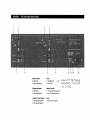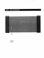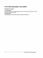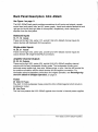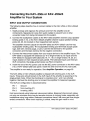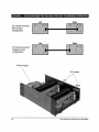
1
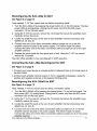
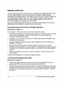
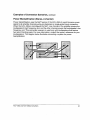
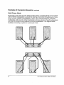
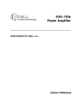
KAV-250a
Leader in Audio Engineering
Stereo PowerAmplifier
KAV-250a/3
Three-Channel Power Amplifier
Instructions for Use,v 99.2
Owner’s Reference
KAV-250aStereo Power Amplifier and
KAV-250a/3 Three-Channel Power Amplifier
Instructions for Use, v 99.2
Cover: KAV-250a/3 Three-Channel Power Amplifier
Krell Industries,Inc.
45 Connair Road
Orange, CT 06477-3650 USA
TEL 203-799-9954
FAX 203-799-9796
E-MAILkrell @krellonline.com
WEBSITEhttp://www.krellonline.com
This product complieswith the EMCdirective (89/336/EEC)and the low-voltage directive
(73/23/EEC).
WARNINGS
Theamplifier mustbe placed on a firm, level surface whereit is not exposedto dripping or
splashing.
Theventilation grids on the top of the amplifier and the spaceunderneaththe amplifier mustbe
unobstructedat all times during operation. Do not place flammablematerial aboveor beneath
the amplifier.
Contactyour authorizedKrell dealer, distributor, or Krell before using anydevicesdesignedto
alter or stabilize the ACpowerfor the KAV-250aor KAV-250a/3.
Before connecting the KAV-250aor KAV-250a/3,makesure the amplifier is off and any output
device (such as a preamplifier) is in muteor stand-bymode.Makesure all cable terminations
are of the highest quality andfree fromfrayed ends,short circuits, or cold solder joints.
Useonly oneset of inputs to the amplifier at a time.
After reconfiguring for MAT,do not use morethan one input at the sametime.
After bridging, do not useboth inputs at the sametime.
THERE ARE NO USER SERVICEABLE PARTS INSIDE ANY KRELL PRODUCT
Pleasecontact your authorizedKrell dealer, distributor, or Krell if youhaveanyquestionsnot
addressedin this reference manual.
This productis manufactured
in the UnitedStatesof America.Krell®is a registeredtrademark
of Krell
Industries,Inc., andis restrictedfor useby Krell Industries,Inc., its subsidiaries,andauthorized
agents.
TM is a trademark
Multi Amp
Throughput
of Krell Industries, Inc. All other trademarks
andtradenames
are
registeredto their respectivecompanies.
© 1999by Krell Industries, Inc. All rights reserved
P/N: I960101710688
Contents
Page
INTRODUCTION’
1
DEFINITION OF TERMS
1
UNPACKING
2
PLACEMENT
3
ACPower Guidelines
3
FRONTPANEL DESCRIPTION: KAV-250a
5
BACK PANEL DESCRIPTION: KAV-250a
7
FRONTPANEL DESCRIPTION: KAV-250a/3
10
BACKPANEL DESCRIPTION: KAV-250a/3
12
CONNECTING
THE KAV-250a or KAV-250aJ3 AMPLIFIER
TO YOUR SYSTEM
14
Input and Output Connections
14
OPTIONAL SYSTEM CONFIGURATIONS
15
Multi AmpThroughput
15
Bridged Operation
20
Examplesof Connection Scenarios
22
AMPLIFIER OPERATION
On/Off and Operation
AMPLIFIER TROUBLESHOOTING
Howto Troubleshoot SystemNoise
25
25
26
26
QUESTION AND ANSWER
27
WARRANTY
28
RETURN AUTHORIZATION PROCEDURE
29
SPECIFICATIONS
30
KAV-250aand KAV-250a/3Amplifiers
iii
Illustrations
Page
FIGURE1 The KAV-250aFront Panel
4
FIGURE 2 The KAV-250aBack Panel
6
FIGURE 3 The KAV-250a/3Front Panel
9
FIGURE 4 The KAV-250a/3 Back Panel
11
FIGURE 5 Reconfiguring the KAV-250afor MAT
or Bridged Operation
16
FIGURE6 Reconfiguring the KAV-250a/3for MAT
or Bridged Operation
iv
19
KAV-250aand KAV-250a/3Amplifiers
Introduction
Thankyou for your purchaseof the Krell KAV-250a
Stereo PowerAmplifier or
KAV-250a/3Three-ChannelPowerAmplifier..
The KAV-250aand KAV-250aJ3
amplifiers provide substantial two- and three-channel
output powerthat delivers realistic musicproductionat an exceptional value. These
amplifiers can be customizedwith a variety of optional systemconfigurations: Multi
AmpThroughput (MAT), bridged operation, and high powermonooperation. These
options provide a wider range of poweroutputs and connection options. Both the KAV250aand KAV-250a/3amplifiers provide balancedand single-ended inputs for
complete compatibility with other components.The KAV-250aand KAV-250a/3
amplifiers can be operatedusing the 12 VDCtrigger for other components.Either
amplifier integrates seamlesslyhometheater or whole-housesystems.
This reference manualcontains important information on placement,installation, and
operation of the KAV-250aand KAV-250a/3amplifiers. Pleaseread this information
carefully. A thoroughunderstandingof these details helps ensuresatisfactory operation
and long life for your KAV-250a
or KAV-250aJ3
amplifier and related system
components.
Definition of Terms
Multi AmpThroughput
An internal connectionoption that sendsthe samemusicsignal to all amplifier channels
using one balancedor single-endedconnection. MATreducesinstallation complexity
and cabling requirementsin systemscontaining multiple amplifiers. MATalso allows a
variety of connectionscenarios, including poweringloudspeakersthat havetwo sets of
binding posts and independentlypoweringmultiple pairs of stereo loudspeakersto
extend the listening environmentthroughout your home.
Bridging
Aninternal connectionoption that links two amplifier channelsto operateas one
combinedamplifier channel, greatly increasing the channel’s poweroutput.
On
Whenthe powerbutton on the front panel is pressedand the blue powerLED
illuminates, the amplifier is on andreadyto play music.
Off
Whenthe powerbutton on the front panel is pressedand the blue powerLEDturns off,
the amplifieris off.
KAV-250aand KAV-250a/3Amplifiers
1
Unpacking
Openthe shipping box, which contains:
1 amplifier unit (packedin foamend-caps)
2 ribbon connection cables
KAV-250afuses:
2 AGC-8 (~ ’amp)
1 slow-blow (20 ampfor 100/120V or 12 ampfor 220/240V)
or
KAV-250a/3fuses:
3 AGC-.8 ~ amp)
1 slow-blow (20 ampfor 100/120V or 12 ampfor 220/240V)
1 12 VDCoutput (12 V trigger) cable
1 IEC connector (AC power) cord
1 T-15 Torx wrench
1 packet containing the owner’s reference manualand the warranty registration
card.
Graspthe undersideof the foamend-capsthat encasethe amplifier andlift the
amplifier straight out of the shippingbox.
Placethe amplifier in a safe location andremovethe protective plastic wrapping.
Notes
If any of these items are not includedin the shippingbox, please contact your
authorizedKrell dealer, distributor, or Krell for assistance.
Saveall packingmaterials. If you ship your amplifier in the future, repackthe unit in its
original packagingto prevent trans# damage.See Return Authorization Procedure,
on page29, for moreinformation.
2
KAV-250aand KAV-250aJ3Amplifiers
Placement
Before you integrate the KAV-250aor KAV-250a/3into your system, review the
following guidelinesto choosethe location for the component.
This will facilitate a
clean, trouble-freeinstallation.
The KAV-250aand KAV-250aJ3
require at least two inches (5 cm) of clearance
eachside and at least two inches (5 cm) of clearance abovethe component
to provide
adequateventilation.
Youramplifier doesnot require any type of special rack or cabinet for installation. For
the dimensionsof your amplifier see Specifications, on pages30 and 31.
Place the amplifier as close to the loudspeakersas possible andkeep the speaker
cable length to a minimum.Speakercable addsimpedanceto the load the amplifier
mustdrive, regardlessof the cable’s gauge.Krell amplifiers drive the lowest
impedanceswith ease, but long speaker cables reduce the maximum
powerthat is
delivered to the loudspeakers.
AC POWER GUIDELINES
Krell recommends
operating each amplifier from a dedicated 15-ampACpowerline.
For maximum
power output, operate the KAV-250aor KAV-250a/3amplifier from a
dedicated 20-ampACpowerline.
KAV-250aand KAV-250a/3Amplifiers
3
FIGURE 1 THE KAV-250a FRONT PANEL
1 2
1 PowerButton
2 Power LED
Front Panel Description: KAV-250a
See Figure 1 on page 4
1 Power Button
Usethis button to turn the KAV-250a
poweron and off and also to switch the 12 VDC
output (12 V trigger) on andoff.
2 Power LED
Theblue powerLEDilluminates whenthe amplifier is on.
KAV-250aand KAV-250a/3Amplifiers
5
FIGURE 2 THE KAV-250a BA(;K PANEL
5
11 12 10
BalancedInputs
3 Right Input
4 Left Input (Bridged)
Fuses
9 AGC~ Fuses
10 Line Fuse
Single-endedInputs
5 Right Input
6 Left Input (Bridged)
RemoteControls
11 12 VDCRemote Power Out
12 12 VDCRemotePower In
Amplifier ChannelOutputs
7 Right Output(Bridged-)
Power
13 IEC Power Connector
8 Left Output(Bridged+)
13
Back Panel Description: KAV-250a
See Figure 2 on page 6
The KAV-250a
back panel provides connectionsfor all inputs and outputs, remote
control input and output links, and ACpowersupply. Inputs andoutputs labeled left and
right are on the left andright side of the amplifier, respectively, whenviewingthe
amplifier fromthe front panel.
Balanced Inputs
3, 4 Inputs
Theseare the right (3) and the left (4) KAV-250a
channelinputs for output devices
balanced XLRconnectors.
Single-ended Inputs
5,6 Inputs
Theseare the right (5) and the left (6) KAV-250a
channelinputs for output devices
single-ended RCAconnectors.
Theleft balancedor single-endedinputs are usedfor bridged operation. See
Reconfiguring the KA V-250afor BridgedOperation, on page 20.
Amplifier Channel Outputs
7 Output Bridged(-)
8 Output Bridged(+)
Theseare the right (7) and left (8) KAV-250a
amplifier channeloutputs with five-way
loudspeakerbinding posts. Theloudspeakerbinding post terminals accept spadelugs,
bare wire, bananaplugs, or pins. Usethe red terminal for the positive connectionand
the black terminal for the.negative connection. For information on loudspeaker
connections for bridged operation, see Reconfiguringthe lEA V-250afor Bridged
Operation, on page20.
Fuses
9 AGC-12 Fuses
TheAGC12 Volt loudspeakerfuses protect the KAV-250a
against short circuits in
loudspeakeroutput.
10 Line Fuse
Theline fuse protects the KAV-250a
against short circuits in internal powersupplies.
Note
Fusesmust be replaced with the fuse value specified on the KAV-250aback panel. Use
a 20 ampslow-blowline fuse for 100/120V systemsor a 12 ampslow-blowline fuse for
220/240 V systems.
KAV-250a
andKAV-250a/3
Amplifiers
7
BackPanelDescription,continued
RemoteControls
11 12 VDC Remote Power Out
12 12 VDCRemotePower In
The KAV-250ais equippedwith an output that sends 12 VDCpoweron/off (12
trigger) signals to other Krell components
andother devicesthat incorporate
12 V trigger. This allows you to turn the KAV-250a
on and off using a Krell or other
component
in a custominstallation.
Notes
12 VDCOut/in (12 V trigger) remotepoweris limited to 30 ma.
Consult the owner’smanualof any component
usedin a custominstallation to take full
advantageof the KAV-250aremotecapability.
Power Supply
13 IEC Connector
TheKAV-250ais equippedwith a standard female IEC powerconnector, for use with
the provided ACpowercord,
8
KAV-250aand KAV-250a/3Amplifiers
FIGURE 3
THE KAV-250a/3 FRONTPANEL
14 15
14 PowerButton
15 Power LED
Front Panel Description: KAV-250a/3
See Figure 3 on page 9
14 Power Button
Usethis button to turn the KAV-250a/3
poweron and off and also to switch the 12 VDC
output (12 V trigger) on andoff.
15 Power LED
Theblue powerLEDilluminates whenthe amplifier is poweredon.
10
KAV-250aand KAV-250a/3Amplifiers
FIGURE 4
16
19
25 22
THE KAV-250a/3
17
BACK PANEL
2o
18
25 23
BalancedInputs
16 Right Input
17 Center Input
18 Left Input
Single-endedInputs
19 Right Input
20 Center Input
21 Left Input
Amplifier ChannelOutputs
22 Right Output
23 Center Output
24 Left Output
21
25 24
27 28 26
Fuses
25 AGCe~Euses ~-----’~
26 Line Fuse
RemoteControls
27 12 VDCRemote Power Out
28 12 VDCRemotePower tn
Power
29 IEC Power Connector
ZOO0.
29
Back Panel Description: KAV-250a/3
See Figure 4 on page 11
The KAV-250a/3back panel provides connectionsfor all inputs and outputs, remote
control input and output links, andACpowersupply. Inputs and outputs labeled left and
right are on the left andright side of the amplifier, respectively, whenviewingthe
amplifier from the front panel.
Balanced Inputs
16, 17, 18 Inputs
Theseare the right (16), center (17), and left (18) KAV-250a/3
channe~inputs
output devices with balancedXLRconnectors.
Single-ended Inputs
19, 20, 21 Inputs
Theseare the right (19), center (20), and left (21) KAV-250a/3
channelinputs
output devices with single-ended RCAconnectors.
Amplifier Channel Outputs
22, 23, 24 Outputs
Theseare the right (22), center (23), and left (24) KAV-250a/3
amplifier channel
outputs with five-way loudspeakerbinding posts. The loudspeakerbinding post
terminals accept spadelugs, bare wire, bananaplugs, or pins. Usethe red terminal for
the positive connectionandthe black terminal for the negative connection.For
information about loudspeakerconnectionsfor bridged operation, see Reconfiguring
the KA V-250aJ’3for BridgedOperation,on page21.
Fuses
25 AGC-12 Fuses
TheAGC12 Volt loudspeakerfuses protect the KAV-250a/3
against short circuits in
loudspeakeroutput.
26 Line Fuse
Theline fuse protects the KAV-250a/3
against short circuits in internal powersupplies.
12
KAV-250aand KAV-250aJ3Amplifiers
BackPanelDescription,continued
Note
Fusesmust be replaced with the fuse value specified on the KAV-250a/3back panel
Use a 20 ampslow-blow line fuse for 100/120V systemsor a 12 ampslow-blow line
fuse for 220/240V systems.
RemoteControls
27 12 VDC Remote Power Out
28 12 VDCRemotePower In
The KAV-250a/3is equippedwith an output that sends 12 VDCpoweron/off (12
trigger) signals to other Krell components
andother devicesthat incorporate
12 V trigger. This allows you to turn the KAV-250aJ3
on and off using a Krell or other
component
in a custominstallation.
Notes
12 VDCOut/In (12 V trigger) remotepoweris limited to 30 ma.
Consult the owner’s manualof eachcomponent
usedin a custominstallation to take full
advantageof the KAV-250a/3remotecapability.
Power Supply
29 IEC Power Connector
TheKAV-250a/3is equippedwith a standard female IEC powerconnector, for use with
the provided ACpowercord.
KAV-250aand KAV-250a/3Amplifiers
13
Connecting the KAV-250aor KAV-250a/3
Amplifier to Your System
INPUT
AND OUTPUT CONNECTIONS
The following steps describe howto connect cables to the KAV-250aor KAV-250a/3
amplifier.
1. Neatly arrangeandorganizethe wiring to and from the amplifier andall
components.SeparateACwires from audio cables to prevent humor other
unwantednoise from being introduced into the system.
21 Connectthe loudspeakercables to the KAV-250aamplifier channel output speaker
binding posts (7, 8), or the KAV-250a/3
amplifier channeloutput speakerbinding
posts (22, 23, 24) located on their respective backpanels.
The amplifier channel outputs for the KAV-250aand KAV-250a/3use five-way
loudspeakerbinding posts. Theloudspeakerbinding post terminals accept spade
lugs, bare wire, bananaplugs, or pins. Usethe red terminal for the positive
connectionand the black terminal for the negative connection.
3. Connectthe interconnect cables from your output device to the amplifier inputs. The
KAV-250a
is equippedwith balanced(3, 4) or single-ended(5, 6) inputs and
KAV-250a/3
is equippedwith balanced(16, 17, 18) or single-ended(19, 20,
inputs located on their respective back panels. Thebalancedinputs use three-pin
XLRconnectors; the single-ended inputs use RCAconnectors.
4. Insert the end of the ACpowercord into the IEC powerconnector on the KAV-250a
(13) or KAV-250a/3
(29) back panel. Insert the other end into the ACwall outlet.
Theamplifier is nowready for operation. SeeAmplifier Operation, on page25.
TheKAV-250aor KAV-250a/3amplifier is shipped with shorting pins in the XLR
inputs. Thesepins shouldremainin the XLRinputs if the amplifier is operatingin the
single-endedmode.Whenthe shorting pin is inserted, pins 1 and 3 are shorted
together. Remove
the shorting pins to connectthe amplifier for balancedoperation.
TheXLRpin configuration is described below:
Pin 1
Ground
°)
Pin 2
Non-inverting(0
°)
Pin 3
Inverting (180
Krell recommends
using balancedinterconnect cables. Balancedinterconnect cables
not only can minimizesonic loss but are also immune
to inducednoise, especially with
installations using long cables. Balancedconnectionshave6 dBmoregain than singleendedconnections.When
level matchingis critical, keepthis gain value in mind.
14
KAV-250aand KAV-250aJ3Amplifiers
Optional SystemConfigurations
The KAV-250aand KAV-250a/3can be reconfigured for either Multi AmpThroughput
(MAT)or bridged operation.
IMPORTANT
Removing
the cover to reconfigure for MAT or for bridged operation is the ONLY
instance you are authorized to removethe cover of ANYKre// componentwithout
voiding your Warranty.For moreinformation on product/imitations and restrictions, see
Warranty, on page 28.
Before Reconfiguringfor MATor Bridged Operation
Readthe following important safety instructions before you attempt to reconfigure your
amplifier for either MATor bridgedoperation:
1. Unplugthe powercord. Unplug the ACpower cord from both the IEC power
connector of the KAV-250a(13) or KAV-250aJ3
(29) on the back panel, and
the ACoutlet.
2. Avoidthe powersupply. After removingthe screws (see instructions below) and
the cover, locate and stay awareof the location of the powersupply. Avoid making
contactwith that area of the amplifier.
3. Remove
jewelry. Rings, necklaces, bracelets, and other pieces of metal jewelry
can conductan electrical charge. Considerremovingthembefore attempting any
reconfiguration.
4. Alwaysreplace cover. Makesure the amplifier’s cover is properly replaced and
securedby the 12 screws before resumingoperation.
IMPORTANT
Operatingthe amplifier without the cover properly replaced and securedmay
void your warranty.
MULTI AMP THROUGHPUT
Multi AmpThroughput(MAT),an internal connection option for either the KAV-250a
the KAV-250a/3,lets you sendthe samemusic signal to all amplifier channelsusing
one balancedor single-endedconnection. MATreducesinstallation complexity and
cabling requirementsin systemscontaining multiple amplifiers.
Inputsandoutputslabeledleft andright are on the left andright side of the amplifier,
respectively, whenviewing the amplifier from the front panel
KAV-250aand KAV-250a/3Amplifiers
15
FIGURE5
RECONFIGURING
THE KAV-250a FOR MATOR BRIDGEDOPERATI( tN
Left
Right
Left
Right
PCboards showing
MATjumper
configuration
PCboards showing
bridged jumper
configuration
Powersupply
PCboards
Right
16
KAV-250a
andKAV-250-a/3
Amplifiers
Reconfiguring the KAV-250afor MAT
See Figure 5 on page 16
Tools needed: T-15 Torx wrenchand one ribbon connection cable
1. Turn the KAV-250a
off by pressing the powerbutton (1) on the front panel. Theblue
powerLED(2) extinguishes. Unplug the ACpowercord from the IEC power
connector(13) on the back panel.
2. Using the T:15 Torx wrench,removethe 12 screwsthat secure the amplifier cover.
Carefully removethe cover.
3. Locate the small PCboardat the rear of eachamplifier channeland jumperpins
labeled J4, J5, andJ6.
4. Connectone end of the ribbon connectioncable to jumperpin J4 on the left
amplifier channel(closest to the powersupply). Theribbon snapsinto place.
Connectthe other endof the ribbon connectioncable to jumperpin J5 on the right
amplifier channel.
5. Replacethe cover (slide the front panel endin first). Usingthe T-15Torx wrench,
secure the 12 screws.
TheKAV-250aamplifier is nowreconfigured for MAToperation.
Connecting the KAV-250aReconfigured for MAT
See Figure 2 on page 6
1. Connectyour output device to a single-endedor balancedinput on the back panel of
the KAV-250a.
2. Connecteachamplifier channeloutput (7, 8) to a separateloudspeaker,using the
positive andnegative terminals on the speakerbinding posts.
Reconfiguring the KAV-250a/3for MAT
See Figure 6 on page 19
Tools needed: T-15 Torx wrenchand two ribbon connection cables
1. Turn the KAV-250a/3
off by pressing the powerbutton (14) on the front panel. The
blue powerLED(15) extinguishes. Unplugthe ACpowercord from the IEC power
connector(29) on the back panel.
2. Using the T-15 Torx wrench,removethe 12 screwsthat secure the amplifier cover.
Carefully removethe cover.
3. Locate the small PCboardat the rear of each amplifier channelandjumperpins
labeled J4, J5, andJ6.
4. Connectone endof the first ribbon connectioncable to jumperpin J4 on the left
amplifier channel(closest to the powersupply). Theribbon snapsinto place.
Connectthe other end of this ribbon connectioncable to jumperpin J5 on the center
amplifier channel.
KAV-250a
andKAV-250a/3
Amplifiers
17
5. Connectone end of the secondribbon connectioncable to jumper pin J4 on the
center amplifier channel. Connectthe other end of this ribbon connectioncable to
jumperpin J5 on the right amplifier channel.
6. Replacethe cover (slide the front panel endin first). Usingthe T-15Torx wrench,
secure the 12 screws.
The KAV-250a/3amplifier is nowreconfigured for MAToperation.
Connecting
the KAV-250a/3 Reconfigured
for
MAT
See Figure 4 on page 11
1. Connectyour output device to a single-endedor balancedinput on the back panel of
the KAV-250a/3.
2. Connecteachamplifier channeloutput (22, 23, 24) to a separateloudspeaker,using
the positive andnegative terminals on the speakerbinding posts.
18
KAV-250aand KAV-250a/3Amplifiers
FIGURE 6 RECONFIGURING
THE KAV-250a/3 FOR MAT OR BRIDGEDOPERATION
Left
Center
Right
PCboards showing
MATjumper
configuration
PCboards showing
bridged jumper
configuration
(See Option 1,
on page21)
PCboards showing
bridged jumper
configuration
(See Option 2,
on page21)
Powersupply
PC boards
ht
KAV-250a
andKAV-250-a/3
Amplifiers
19
BRIDGED OPERATION
The KAV-250a
andthe KAV-250a/3
can be reconfigured for bridged operation. When
the KAV-250a
amplifier’s channelsare bridged,the amplifier’s outputpoweris
quadrupled:the amplifier delivers 1,000Wattsto an 8 Ohm
load. TheKAV-250a/3
can
be reconfiguredto bridgeanytwo of its three amplifier channels
to operateas one
combined
amplifier channel.When
using the bridgedamplifier channelonly, the
KAV-250a/3
delivers 1,000 Wattsto an 8 Ohmload.
Inputsandoutputslabeledleft andright areonthe left andright sideof the amplifier,
respectively,whenviewingthe amplifier fromthe front panel
Reconfiguring the KAV-250afor Bridged Operation
See Figure 5 on page16
Tools needed:T-15Torx wrenchandoneribbon connectioncable
off by pressingthe powerbutton (1) on the front panel. Theblue
1. Turnthe KAV-250a
powerLED(2) extinguishes. Unplugthe ACpowercord from the IECpower
connector(13) on the backpanel.
2. Usingthe T-15Torxwrench,removethe 12 screwsthat securethe amplifier cover.
Carefully removethe cover.
3. Locatethe small PCboardat the rear of eachamplifier channelandjumperpins
labeledJ4, J5, andJ6.
oneendof the ribbonconnectioncableto jumperpin J4 on the left
4. Connect
amplifier channel(closest to the powersupply). Thecablesnapsinto place. Connect
the other endof the ribbonconnection
cableto jumperpin J6 on the right amplifier
channel.
cover(slide front panelendin first). Usingthe T-15Torxwrench,secure
5. Replace
the 12 screws.
TheKAV-250a
amplifier is nowreadyfor bridgedoperation.
Connecting the Bridged KAV-250a
SeeFigure 2 on page6
1. Connectthe output cablefrom the outputdeviceto the balancedXLR(4/ or the
single-endedRCA(6) inputs connectorsmarked(BRIDGED~NPUT).
2. Connect
the positive loudspeaker
lead (red) to the positive bindingpost on the left
amplifier channeloutput (8), markedBRIDGED(+). Connectthe negativeloudspeaker
lead (black) to the positivebindingpost on the right amplifier channel
(7), marked
BRIDGED
(-).
20
KAV-250a
andKAV-250a/3
Amplifiers
IMPORTANT
Whenoperating the amplifier in bridged modeand using an output device with
single-ended RCAcables, be sure to removethe shorting pin from the/eft balanced
XLRinput (4).
Reconfiguringthe KAV-250a/3for Bridged Operation
See Figure 6 on page 19
Tools needed: T-15 Torx wrenchand two ribbon connection cables
1. Turn the KAV-250a/3
off by pressing the powerbutton (14) on the front panel. The
blue powerLED(15) extinguishes. Unplugthe ACpowercord from the IEC power
connector(29) on the back panel.
2. Usingthe T-15 Torx wrench,removethe 12 screwsthat secure the amplifier cover.
Carefully removethe cover.
3. Locatethe small PCboard at the rear of eachamplifier channeland jumperpins
labeled J4, J5, andJ6.
4. Option 1: To bridge left and center amplifier channels,connectoneend of the
ribbon connectioncable to jumperpin J4 on the left amplifier channel(closest to the
powersupply). Thecable snapsinto place. Connectthe other end of the ribbon
connectioncable to jumperpin J6 on the center amplifier channel.
Option 2: To bridge center and right amplifier channels, connectone end of the
ribbon connectioncable to jumperpin J4 on the center amplifier channel. Connect
the other endof the ribbon connectioncable to jumperpin J6 on the right amplifier
channel.
5. Replacecover (slide the front panel endin first). Usingthe T-15Torx wrench,
secure the 12 screws.
The KAV-250aJ3
amplifier is nowready for bridged operation.
Connecting the Bridged KAV-250a/3
See Figure 4 on page 11
1. Whenthe left and center amplifier channelsare bridged (Option 1), connectthe
output cable from the output device to the center balancedXLR(17) or single-ended
RCA(20) input.
Connectthe positive loudspeakerlead (red) to the positive binding post on the
center amplifier channel(23). Connectthe negative loudspeakerlead (black) to
positive bindingpost of the left amplifier channel(24).
KAV-250aand KAV-250a/3Amplifiers
21
2. When
the center and right amplifier channelsare bridged (Option 2), connectthe
output cable from the output device to the right balancedXLR(16) or single-ended
RCA(19)input.
Connectthe positive loudspeakerlead (red) to the positive binding post on the
(right) amplifier channel(22). Connectthe negative loudspeakerlead (black)
positive binding post of the center amplifier channel(23).
The remaining channel maybe connectedfor normal operation.
IMPORTANT
Whenoperating the amplifier in bridged modeand using an output device with a
single-ended RCAcable, be sure to removethe shorting pin from the balancedXLR
input.
EXAMPLESOF CONNECTION SCENARIOS
High Power MonoOperation
High powermonooperation uses two KAV-250a
bridged amplifiers: one amplifier is
dedicatedto the left loudspeakerandoneamplifier is dedicatedto the right
loudspeaker. Additional loudspeakersin a hometheater systemmaybe connectedin
this wayby using additional KAV-250a
amplifiers. Thediagrambelowillustrates
connecting a systemfor high powermonooperation:
22
KAV-250aand KAV-250a/3Amplifiers
Examples of Connection Scenarios, continued
Power Biamplification
(Stereo,
2-channel)
Powerbiamplification uses the MATfeature of the KAV-250ato send the samemusic
signal to all amplifier channelsusing onebalancedor single-endedinput connection.
Whenthe KAV-250ais reconfigured for MAT,one channel of the amplifier powersthe
Ioudspeaker’shigh frequency end, and the other channel powersthe Ioudspeaker’slow
frequencyend. This connectionscenario is usedonly with loudspeakersthat feature
two sets of binding posts. For moreinformation, consult the owner’sreferencefor your
loudspeakers.Thediagrambelow illustrates connectinga systemfor power
biamplification:
KAV-250aand KAV-250aJ’3Amplifiers
23
Examplesof Connection Scenarios,
continued
Multi Power Mode
Multi powermodeuses the KAV-250a/3’s
MATfeature to independentlypowermultiple
pairs of stereo loudspeakers
to extendthe listening environment
throughoutyour home.
Whenthe KAV-250a/3
is reconfiguredfor MAT,eachchannelpowersan individual
loudspeaker,with oneKAV-250a/3
dedicatedto driving outputsto the left loudspeakers
andoneKAV-250a/3
driving outputsto the right loudspeakers.Thediagrambelow
illustrates connecting
a systemfor multi powermode:
24
KAV-250aand KAV-250aJ3Amplifiers
Amplifier Operation
ON/OFF
AND OPERATION
Whenpowering up your system, turn amplifiers on last. Whenpowering downyour
system,turn amplifiers off first. Theprocedures
for amplifier operationfollow.
1. Press the KAV-250apowerbutton (1) or KAV-250a/3powerbutton (14) on
amplifier’s front panel. Wait until the blue powerLED(2) on the KAV-250a
or (15)
on the KAV-250a/3
illuminates and you hear a click. Theamplifier is nowready for
operation.
2. With the output device mutedor volumecontrol fully lowered, select an output
device. Decrease
or increasethe volumecontrol to the desired listening level.
3. Before turning the systemoff, muteor lower the output device volume.Pressthe
front panelpowerbuttonto turn the amplifier off. It is nowsafe to turn off the rest of
the system.
IMPORTANT
Alwaysturn off the amplifier before changinginput connections,andmuteor fully
attenuate the preamplifier level whenswitching sources.
Theseamplifiers have tremendousreserves of powerand safely drive loudspeakersto
extremely high soundpressure levels. However,use care whensetting high playback
levels andlower the volumelevel at any sign of loudspeakerdistress.
KAV-250aand KAV-250a/3Amplifiers
25
Amplifier Troubleshooting
HOW TO TROUBLESHOOT
SYSTEM NOISE
Whenyou mix and matchaudio components,each with its ownground potential, a low
frequency hummayoccur in one or both loudspeakers. This often occurs when
introducing a newcomponentinto a system.
If a low frequency humemanatesfrom the loudspeakers whenyou place the KAV250astereo or KAV-250a/3
three-channel amplifier into your system, follow these
simple troubleshooting steps.
1, Checkall input and output connections, makingsure they are of soundconstruction.
2. With the amplifier off, removethe interconnect cables, then press the KAV-250a
powerbutton (1) or KAV-250a/3
powerbutton (14) to turn the amplifier
3. If the humdisappears,press the powerbutton again to turn the amplifier off and
reinsert oneof the interconnectcables.
4. Turn the amplifier back on. If the humreappearswith oneor both interconnect
cables inserted, there maybe a defective cable. Havethe interconnect cables
checkedbefore proceeding.
If the interconnect cables are sound,you maybe experiencinga groundloop. This can
often be easily eliminated. Pleasecontact your authorizedKrell dealer, distributor, or
Krell for suggestionson howto solve this problem.
26
KAV-250aand KAV-250a/3Amplifiers
Question and Answer
Q. Should I leave the KAV-250a
or KAV-250a/3amplifier on at all times?
A. No. Theseamplifiers do not havea stand-by mode.Leavingthemon at all times
wouldresult in considerableheat output andpowerconsumption.For best results, turn
the amplifier off whennot in use, andallow a five minutewarm-up
after it is turnedon.
See Amplifier Operation, on page25.
QoWhenI turn the amplifier on there is a loud humthrough the loudspeakers.What
should I do?
A. Whena newcomponentis introduced, a low frequency hummayoccur in one or
both loudspeakers.Checkall input and output connectionsand cables, makingsure
they are of soundconstruction. See Howto Troubleshoot SystemNoise, on page 26.
If the connectionsand cables are sound, you maybe experiencing a groundloop. This
can often be easily eliminated. Pleasecontact your authorizedKrell dealer, distributor,
or Krell for suggestionson howto solve this problem.
Q. WhenI connectthe amplifier to mysystemusing the single-endedinputs, a loud
buzz comesfrom my loudspeakers.Is the amplifier broken?
A. Checkthat the shorting pins for the KAV-250a
or KAV-250a/3
are inserted into the
XLRinputs (the unit is shippedwith the pins in place). Whenusing the single-ended
inputs, these shorting pins mustbe inserted betweenpins 1 and 3 to keepexternal
noise from corrupting the signal. For moreinformation, see Connectingthe KAV-250a
or KAV-250a/3 Amplifier to Your System, on page 14.
KAV-250aand KAV-250a/3Amplifiers
27
Warranty
The KAV-250aand KAV-250a/3
amplifiers have. a limited
andtransferable warrantyof five yearsfor parts andlabor
on cimuitry. Shouldthis productfail to performat anytime
during the warranty,Krell will repair it at no cost to the
owner,exceptas set forth in this warranty.
This warranty does not apply to damage
causedby acts of
Godor nature.
Thewarrantydescribedon this pageshall be in lieu of any
other warranty,expressed
or implied, including, but not limited to, anyimpliedwarrantyof merchantability
or fitness for
a particular purpose.Thereare no warrantieswhichexceed
beyondthose describedin this document.If this product
does not perform as warrantedherein, the owner’s sole
remedy
shall berepair. In noeventwill Krell beliable for incidental or consequential damagesarising from purchase,
use, or inability to usethis product,evenif Krell hasbeen
advisedof the possibility of suchdamages.
The warrantypedodbegins on the date of retail purchase,
as notedon the retail sales slip providedby an authorized
Krell dealeror distributor, or onthe warrantyregistration
card sent to Krell. In the eventadequateproof of purchase
date is unavailable, the warrantypedodwill begin on the
date the unit wasoriginally shippedfromthe factory. Krell
can determinethe original ship date fromthe serial number.
Transfer of warranty to a second owner occurs automatically. PleasecontactKrell to havethe registrationon the
warranty changed.When
the warranty is transferred, any
successive owner assumesthe remainder of the odginal
warrantyperiod.
Thewarrantyfor Krell productsis valid only in the countryto
whichthey wereoriginally shipped,throughthe authorized
Krell distributor for that country,andat the factory. There
maybe restrictions on or changesto Krell’s warranty
becauseof regulations within a specific country. Please
checkwith your distributor for a completeunderstanding
of
the warrantyin your country.
If a unit is servicedby a distributor whodid not importthe
unit, there maybe a chargefor service, evenif the product
is within the warrantyperiod.
Freight to the factory is your responsibility. Returnfreight
within the UnitedStates(U.S.A.)is includedin the warranty.
If you havepurchased
your Krell productoutsidethe U.S.A.
andwish to haveit servicedat the factory, all freight and
associatedchargesto the factory are your responsibility.
28
Krell will payreturn freight to the U.S.A.-based
freight forwarderof your choice. Freight andother chargesto ship the
unit fromthe freight forwarderto youare also your responsibility.
Krell is not responsiblefor anydamage
incurred in transit.
Krell will file claimsfor damages
as necessary
for units damagedin transit to the factory. Youare responsiblefor filing
claims for shipping damages
during the return shipment.
Krell doesnot supplyreplacement
parts and/or productsto
the ownerof the unit. Replacement
parts and/or products
will be furnishedonly to the distribtuor performing
serviceon
this unit on an exchange
basis only; anyparts and/or products returned to Krell for exchange
become
the property of
Krell.
No expressedor implied warranty is madefor any Krell
product damaged
by accident, abuse, misuse, natural or
personaldisaster, or unauthorized
modification.
Any unauthorized voltage conversion, disassembly,
componentreplacement, perforation of chassis,
updates, or modifications performedto the unit will
void the warranty.
Theoperatingvoltageof this unit is determined
by the factory andcan only be changed
by an authorizedKrell distributor or at the factory. Thevoltage for this productin the
U.S.A.cannotbe changed
until six monthsfromthe original
purchasedate.
In the eventthat Krel] receivesa productfor warrantyservice that hasbeenmodifiedin any waywithout Krell authorization, all warrantiesonthat productwill bevoid. Theproduct will bereturnedto original factorylayoutSl~ecifications
at
the owner’s expensebefore it is repaired. All repairs
requiredafter the producthas beenretumedto odginalfactory specificationswill be chargedto the customer,at current parts andlabor rates.
All operational features, functions, andspecifications and
policies are subjectto change
withoutnotification.
To register your product for warranty benefits,
complete
and return
the Warranty
Registration
Card enclosed in the shipping
box within 15 days of purchase. Thank you.
KAV-250aand KAV-250a/3 Amplifiers
ReturnAuthorization
Procedure
To return this productto Krell, please
follow this procedure so that we may
serve youbetter:
1. Obtain a Return Authorization Number
(R/A number) and shipping address
from the Krell Service Department.
If you believe there is a problemwith your
component,
please contact your dealer, distributor, or the Krell factory to discussthe
problembefore you return the component
for 2. Insureandacceptall liability for loss of
repair. Toexpediteservice, you maywish to
or damage
to this product during shipcomplete and e-mail the Service Request
mentto the Krell factory andprepayall
shipping charges. Please see the
Formin the Service Section of our website
at:
Warrantypagein this manual,concerning liability
for shipping damage
and
http://www.krellonline.com
shipping charges.
To contact the Krell Service Department
TEL
FAX
E-MAIL
203-799-9954
Monday-Friday
9:00 AMto 5:00 PMEST
203-799-9796
service@
krellonline.com
WEBSITE http://www.krellonline.com
PRODUCTNAME
SERIAL NUMBER
This product mayalso be handdelivered if
arrangementswith the Service Department
have beenmadein advance.Proof of purchasewill be required for warrantyvalidation at the timeof handdelivery.
IMPORTANT
Usethe original packagingto ensuresafe
transit of this productto the dealer,distributor, or factory. Krell may,at its discretion,
return this productin newpackaging
andbill
the ownerfor suchpackagingif the product
received by Krell was boxedin non-standard packagingor if the original packaging
was so damagedthat it was unusable. If
Krell determines that new packaging is
required, the ownerwill be notified before
this productis returned.
To purchaseadditional packaging, please
contactyourauthorizedKrell dealer, distributor, or the Krell ServiceDepartment.
29
KAV-250aand KAV-250a/3Amplifiers
Specifications
KAV-250aStereo Amplifier
FREQUENCY RESPONSE
20 Hz to 20 kHz +0 dB, -0.1 dB
0.4 Hz to 170 kHz +0 dB, -3 dB
SIGNAL TO NOISE RATIO
"A" WEIGHTED
118dB
TOTAL HARMONICDISTORTION (THD)
1 kHz < 0.06%
20 kHz < 0.25%
GAIN
26.4 dB
INPUT IMPEDANCE
100 kOhms
INPUT SENSITIVITY
2.15 Vrms
OUTPUT VOLTAGE
Peak to Peak
RMS
138 V
49 V
OUTPUT POWER, EACH CHANNEL
8 Ohms
250 W
DRIVEN
4 Ohms
500 W
BRIDGED
8 Ohms
1,000 W
POWER CONSUMPTION
Idle
210W
Max.
1,850 W
INPUTS
1 pair single-ended via RCAconnectors
1 pair balancedvia XLRconnectors
OUTPUTS
1 pair amplifier channelsvia five-way speaker
binding posts
DIMENSIONS
19wx 6.3h x 15.3din.
48.3w x 16h x 38.9d cm
WEIGHT
30
Shipping
50 lb., 22.7 kg
Unit only
43 lb., 19.5 kg
KAV-250a
and KAV-250a/3
Amplifiers
KAV-250a/3 Three-Channel Amplifier
FREQUENCY RESPONSE
20 Hz to 20 kHz
+0 dB, -0.2 dB
0.4 Hz to 112 kHz +0 dB, -3 dB
SIGNAL TO NOISE RATIO
"A" WEIGHTED
118dB
TOTAL HARMONICDISTORTION (THD)
1 kHz < 0.06%
20 kHz < 0.25%
GAIN
26.4 dB
INPUT IMPEDANCE
100 kOhms
INPUT SENSITIVITY
2.15 Vrms
OUTPUT VOLTAGE
Peak to Peak
RMS
138 V
49 V
OUTPUT POWER, EACH CHANNEL
8 Ohms
250 W
DRIVEN
4 Ohms
500 W
BRIDGED
8 Ohms
1,000 W
POWER CONSUMPTION
Idle
Max.
INPUTS
235 W
1,930 W
3 single-ended via RCAconnectors
3 balanced via XLRconnectors
OUTPUTS
3 amplifier channelsvia five-way speaker
binding posts
DIMENSIONS
19wx 6.3h x 15.8d in.
48.3w x 16h x 40.1d cm
WEIGHT
Shipping
60 lb., 27.2 kg
Unit only
52 lb., 23.5 kg
All operationalfeatures, functions, specifications, andpolicies are subject to changewithout
notification.
KAV-250a
and KAV-250a/3Amplifiers
31
Krell Industries,Inc.
45 Connair Road
Orange, CT 06477-3650USA
TEL 203-799-9954
FAX203-799-9796
E-MAIL
[email protected]
WEBSITE
http://www.krellonline.corn
KAV-250a
Stereo Power Amplifier
KAV-250a/3
Three-Channel Power Amplifier