1
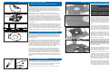
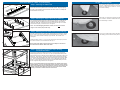
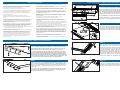
Safety Guidelines
7.
· Woodworking machines are dangerous, and can cause personal injury if not
used properly.
· Keep children and visitors away. All children and visitors should be kept a safe distance
from the work area, and should not operate the tool under any condition.
· Read safety instructions and operating instructions for your machine completely,
before using products. Using this system before understanding its safe and
proper use could result in serious injury to the operator.
· Make your workshop “child-proof”. Use padlocks, master switches, or any other means
necessary to make your work area safe for children.
· Use the right tool. Never ‘force’ the tool to do work for which it was not intended. If used
properly, the tool will produce better results in less time, under safer conditions.
· Failure to follow these rules may result in serious personal injury.
· For your own safety, read instruction manual before operating the tool. Learn the
tools application and limitations as well as the specific hazards distinctive to it.
· Keep all guards and safety devices in proper place while using these products.
· Wear proper apparel. No loose clothing, gloves, neckties, rings, bracelets, or any other
jewelry that could possibly get caught in moving parts. Non-slip footwear is highly
recommended, as is protective hair covering. Remember to always use safety glasses,
specifically designed as safety wear.
· Keep hands well away from the rotating bit when operating machine.
· Secure the workpiece. Use clamps or a vise to hold work when it is practical and safe.
Using the proper tool may allow you to free both hands for tool operation. Also, be sure
to never overreach.
· Avoid akward hand positions, where a sudden slip could cause contact with the
rotating bit.
· Secure your tools. In the event of the machine tipping or sliding, it is always
recommended to secure your tools to the machine during use.
· This system was designed for certain applications only. Kreg strongly recommends
that this system NOT be modified and/or used for any application other than
for which it was designed. If you have any questions relative to its application,
DO NOT use the tool until you have written, phoned, or e-mailed Kreg Tool and
have been advised accordingly.
· Keep the proper footing and balance. Ensure that you are in no danger of slipping or
sliding once you turn the machine on. Once again, non-slip footwear is highly
recommended.
· Always wear safety glasses.
· Be aware of kickbacks. Kickbacks occur when the workpiece binds-up while being
routed, causing it to twist, jump, and possibly become airborne. To avoid kick
backs (and potential injury) always use sharp bits, keep the machine aligned and
maintained properly, and adequately secure/support the workpiece.
· Turn machine off before adjusting. Never adjust the fence, plate level, reducing rings,
or any other part of the tool while the machine is running.
· Wait for the machine to stop. Make sure the router comes to a complete stop before
adjusting the workpiece or workpiece-angle.
· Ground electric machines. If your machine is equipped with a three-prong plug, it
should be plugged into a three-hole electrical receptacle only. If the proper
outlet is not available, have one installed by a qualified electrician before use.
Never remove the third prong, and never modify the provided plug in any way.
· Don’t operate in a dangerous or unclean environment. Don’t use power tools in
damp or wet locations, or expose them to rain. Keep work area well-lit,
un-cluttered, and clean.
Precision
Router Table Top
(24” x 32”)
ASSEMBLY INSTRUCTIONS
Item# PRS1020
· Maintain tools in top condition. Keep tools sharp, clean, and properly maintained for the
highest quality and safest performance. Remember to properly follow all lubrication and
accessory maintenance practices, as detailed in this Instruction Manual.
· Disconnect tool before servicing. When changing accessories such as bits, clamps, etc.,
making any sort of physical assessment of the tool, or when motor is being mounted/
connected, remember to disconnect the machine from its power source. This will reduce
the possibility of accidentally engaging the machine.
· Check for damaged parts. Before use of the tool, a careful assessment of all guards and
other parts should be made to ensure that it will operate properly, and perform as
intended. Check for alignment of moving parts, binding of moving parts, breakage of
parts, mounting, and any other conditions that may affect its operation. A guard or other
part that is damaged should be properly repaired or replaced as soon as possible,
preceding any additional use. Do not use the tool if you are not qualified to make these
sorts of assessments.
· Never leave a running machine unattended. Always turn the machine’s power “OFF”
after operation. Do not leave the tool until it comes to a complete stop.
· Drugs, alcohol, medication warning. Do not operate tool while under the influence of
drugs, alcohol, or any medications.
Other Precision Routing Products
Come meet the entire family of Precision Routing Products
at www.kregtool.com
Tools Required:
• 5/64” Allen Wrench
• Phillips Head Screwdriver
• Flat Head Screwdriver
• 6” #2 Square Driver
• 1/8” Allen Wrench (Included)
• 3” #2 Square Driver (Included)
Item# PRS1010
Item# PRS3010
TM
True-FLEX Featherboard
Precision Router Table Fence
This unique featherboard can be quickly and easily connected to almost any
miter slot or t-slot without the need for additional hardware. It features a durable
plastic composite body which ensures optimum workpiece pressure.
Taking cues from high-end table saw rip fences, this groundbreaking router
fence provides an entirely new way to work. It’ll make every project you
start faster, easier, and far more precise than ever before.
www.kregtool.com • 800.447.8638
www.kregtool.com • 800.447.8638
Version 20070701 RT10116
1.
Precision Router Table Top Assembly
Step 1: Attaching the T-Miter Trak
Your table should have shipped with the T-Miter Track (#3) already inserted
into the slot on the front portion of the router table surface. Begin by aligning
the Trak to the pre-drilled holes and attach with three 10-32 x ¾” Phillips Flat
Head Machine Screws (#15).
Step 2: Mounting the Support Struts to the Table Top
Turn the Router Table top (#2) so it’s face down on the floor. Locate the two
Support Struts (#7) and align them to the pre-drilled holes in the bottom of
the Router Table Top. Mount the struts to the top using the eight ¾” Coarse
Thread Screws (#16). Be careful not to over tighten.
In Use: Starting Pin
6.
The starting pin included with your router table is useful when routing
curves. It supports the edge of your work piece and allows you to gently
ease your work into the router bit. It should only be used with router bits
that have a bearing.
Start with your work piece touching the starter pin, but not in contact with
the router bit. Ease the material into the cutter and make contact with
the ball bearing on the bit.
Note: To avoid damaging the table’s surface, be sure not to use the
longer 1-1/4” screws (#11) on this step.
Step 3: Mounting the Insert Plate Levelers to the Table Top
Use the curved tab on the Insert Plate Levelers (#8) to locate each Leveler
in the corner of the Insert Plate opening and fasten them in to place using
three 1-1/4” coarse thread screws (#11) per leveler. Be careful not to
overtighten.
Thread the eight 1/4-20 x 1-1/2” cup point socket set screws (#10) into the
two holes as shown, and thread about half way in.
Note: These Insert Plate Levelers will be used in Step 6 to mount and
level the Precision Router Table Insert Plate.
Step 4: Mounting the Router Table Top to the Kreg
Universal Steel Stand
For proper mounting and alignment purposes, it’s best to leave the Router
Table Top (#2) face down on the floor. Turn the Universal Steel Stand upside
down and align the four rails with the pre-drilled holes on the bottom side of the
Table Top. The Kreg logo, located on the front of the stand should be located
on the same side and parallel to the T-Miter Track opening on the Router Table
Top. Once the table is positioned correctly, use a 6” #2 Square driver bit and
twelve ¾” Coarse Screws (included with the Universal Steel Stand) to secure
the two together, being careful not to over tighten.
Note: The included hardware was intended for use with the Kreg Universal Steel Stand. If you are working with another stand, be sure to doublecheck your hardware sizes to ensure that the screws do not puncture the
surface of the top when tightened. Also be sure to leave the 6” slotted
opening on the table’s surface free from obstruction.
Once you’ve made solid contact with the ball bearing you can ease off of
the starting pin and allow the work piece to glide along the bit’s bearing.
5.
Precision Router Table Top Assembly
Step 6: Leveling the Insert Plate to the Opening
The unique design of the Precision Insert Plate Levelers (#8) and
adjustable leveling screw system applies pressure to both sides of
the Insert plate so that – once locked in – the Insert Plate stays flush
regardless of the weight applied. The 8 Leveling Screws and 4 LockDown screws work together to keep the Insert Plate flush with the router
table surface at all times.
Set the eight ¼-20 x 1-½” Cup Point Socket Set Screws (#10) to
aproximately the same height and lay the Insert Plate into the opening.
The Insert Plate should be resting on the eight adjustable Set Screws.
Using the 1/8” Allen Wrench (included), adjust the set screws from the
bottom side of the Insert Plate, being careful to adjust each screw the
same distance as the other. Adjust the Insert Plate as close as possible
to flush with the surface of the router table top and run your finger along
the perimeter of the Insert Plate to check that all edges are flush with the
router table top.
Thread the four ¼-20 x 1-3/4” Phillips Flat Head Machine Screw (#12)
(Lock-Down Screws) through the countersunk holes into the center hole
on each leveler and snug down. Run your finger along the perimeter
of the Insert Plate again to check that all edges are flush with the router
table top. Some loosening or tightening of the lock down screws might be
necessary to help adjust the reducing ring and hold it securely in place.
Step 7: Installing & Leveling the Reducing Rings
Note: We recommend adjusting both reducing rings at this time. This will
save time later as you change which reducing ring you want to use, and
also reduces the possibility of losing the second set of small Flat Point
Socket Set Screws. After you have leveled one reducing ring, remove it
and level the other.
Insert three 8-32 x ¼” Flat Point Socket Set Screws (#13) into reducing
ring’s threaded holes, using a 5/64 Allen Wrench as shown. Place the
reducing ring into the Insert Plate opening and rotate counter-clockwise
until the set screws fall into the corresponding holes. Adjust the set
screws until the reducing ring is perfectly level with the Insert Plate.
Secure the reducing ring by threading the 8-32 x 5/16” Phillips Flat Head
Machine Screws (#14) into their holes and tightening snuggly.
As you tighten down the reducing ring, some additional adjustment
under tension may be necessary. Adjust each set screw as needed to
bring the reducing ring flush with the insert plate. Some loosening or
tightening of the lock down screws might be necessary to help adjust
the reducing ring and hold it securely in place. By leveling the reducing
rings while force is applied in both directions, the rings will stay flush
regardless of the weight applied, providing a more level and secure work
surface.
Step 8: Installing the Starting Pin
Thread the ¼-20 x ¾” Cut Point Socket Set Screw into the bottom of the
Brass Starting Pin using a flat head screw driver and a 1/8” allen wrench,
until the two are secured tightly together. Insert the Starting Pin assembly
into the Insert Plate Start Pin Hole and thread in until tight.
* For more information on how to use the starting pin, please see page 6.
Precision Router Table Top Assembly
2.
Step 5: Mounting the router to the Insert Plate
PLEASE NOTE:
All routers are different. When aligning the router’s base plate to
the bull’s-eye template and Insert Plate, take into consideration all of
the controls you will need access to when the router is suspended
below the plate during operation. Plan your installation completely
and adjust the router orientation accordingly. The router handles do
not need to be square with the table or plate for proper operation, so
easy access to the on/off switch and other controls should be your
#1 priority when attaching the router to the Insert Plate.
Begin by locating the 3/8” phenolic Insert Plate (#1) and placing it face
down on your workbench. The Kreg Logo on the Insert Plate should not
be visible. Take the clear Plastic Template and place the edge marked
“FRONT” towards the front edge of the insert plate. Align the template
so that the Start Pin Hole marking and the bull’s-eye line up perfectly with
the Insert Plate. Once positioned correctly, securely tape the template into
place.
In a later step, you will be duplicating your router’s base plate holes into
your Insert Plate so that you can connect your router directly to the Insert
Plate. First, you must determine the correct size of the holes to drill in
your Insert Plate. Remove the base plate from your router and find the bit
that fits just inside of the base plate’s holes.
Now, center your base plate on the concentric rings of the bull’s-eye
template. Keep in mind what position you want the router in when it’s
suspended from the table and make certain the base is rotated to reflect
that position. For instance, it’s best to have the lock on the router base,
and the controls on the router motor, toward the front of the table, or as
easily accessible as possible.
Note: If your router is equipped with a built-in lift system, you will need to
drill the appropriate holes through the insert plate at this time to gain access
to the system and make adjustments to the bit depth of your router after
it’s been mounted to the insert plate. Once again, use your router base
plate to choose the appropriate size drill bit needed for these holes. VERY
IMPORTANT – When positioning your base plate for drilling, make sure that
none of the holes you are about to drill line up over the pre-drilled Start Pin
Hole in the insert plate.
Once you have the base plate from your router aligned where you want it
on the template, use heavy duty masking tape to secure your base plate
to the bull’s-eye template. Tape on at least four sides of your base plate to
ensure a strong and secure hold.
Whether you use a drill press or hand drill, we recommend you place a
scrap piece of wood under the insert plate. This will reduce blowouts as
you drill through the insert plate. It’s easiest to do this operation on a drill
press so the holes are perfectly square to the insert. If you must drill it by
hand, be careful to keep the holes straight. Before drilling, securely clamp
the insert plate to your bench or drill press to hold it secure and reduce the
chance of the material moving as you drill.
After the holes are drilled, remove the base plate & template. Flip the
insert plate over and use an 82 degree countersink bit to countersink each
hole so the head of the screws sit at flush or slightly below the plate’s
surface when tightened down. Be very careful not to over drill these holes,
as their depth will directly affect the quality of your routing surface.
Precision Router Table Top Exploded Parts Diagram
3.
Hardware
Item#
F
A
Part#
Quantity
1
A
Phenolic Insert Plate
RT10101
1
2
B
Table Top
RT10102
1
3
C
T-Miter Track
RT10103
1
4
D
2” Reducing Ring
RT10107
1
5
E
1-13/64” Reducing Ring
RT10106
1
6
F
Brass Starting Pin
RT10108
1
7
G
Support Strut
RT10171
2
8
H
Insert Plate Leveler
RT10100
4
9
1/4-20 x 3/4” Set Screw
DK1522
1
10
1/4-20 x 1-1/2” Set Screw
RT10111
8
11
1-1/4 Coarse Screw
SML-C125
12
12
1/4-20 x 1-3/4” Flat Head MS
RT10112
4
13
8-32 x 1/4” Set Screw
RT10110
6
14
8-32 x 5/16” Flat Head MS
RT10109
3
15
10-32 x 3/4” Flat Head MS
DK1547
3
16
3/4” Coarse Screw
RT10192
8
C
D
Description
4.
B
Slot to attach Kreg
Precision Router
Table Fence.
E
H
G
G
2
5.
Precision Router Table Top Assembly
Step 6: Leveling the Insert Plate to the Opening
The unique design of the Precision Insert Plate Levelers (#8) and
adjustable leveling screw system applies pressure to both sides of
the Insert plate so that – once locked in – the Insert Plate stays flush
regardless of the weight applied. The 8 Leveling Screws and 4 LockDown screws work together to keep the Insert Plate flush with the router
table surface at all times.
Set the eight ¼-20 x 1-½” Cup Point Socket Set Screws (#10) to
aproximately the same height and lay the Insert Plate into the opening.
The Insert Plate should be resting on the eight adjustable Set Screws.
Using the 1/8” Allen Wrench (included), adjust the set screws from the
bottom side of the Insert Plate, being careful to adjust each screw the
same distance as the other. Adjust the Insert Plate as close as possible
to flush with the surface of the router table top and run your finger along
the perimeter of the Insert Plate to check that all edges are flush with the
router table top.
Thread the four ¼-20 x 1-3/4” Phillips Flat Head Machine Screw (#12)
(Lock-Down Screws) through the countersunk holes into the center hole
on each leveler and snug down. Run your finger along the perimeter
of the Insert Plate again to check that all edges are flush with the router
table top. Some loosening or tightening of the lock down screws might be
necessary to help adjust the reducing ring and hold it securely in place.
Step 7: Installing & Leveling the Reducing Rings
Note: We recommend adjusting both reducing rings at this time. This will
save time later as you change which reducing ring you want to use, and
also reduces the possibility of losing the second set of small Flat Point
Socket Set Screws. After you have leveled one reducing ring, remove it
and level the other.
Insert three 8-32 x ¼” Flat Point Socket Set Screws (#13) into reducing
ring’s threaded holes, using a 5/64 Allen Wrench as shown. Place the
reducing ring into the Insert Plate opening and rotate counter-clockwise
until the set screws fall into the corresponding holes. Adjust the set
screws until the reducing ring is perfectly level with the Insert Plate.
Secure the reducing ring by threading the 8-32 x 5/16” Phillips Flat Head
Machine Screws (#14) into their holes and tightening snuggly.
As you tighten down the reducing ring, some additional adjustment
under tension may be necessary. Adjust each set screw as needed to
bring the reducing ring flush with the insert plate. Some loosening or
tightening of the lock down screws might be necessary to help adjust
the reducing ring and hold it securely in place. By leveling the reducing
rings while force is applied in both directions, the rings will stay flush
regardless of the weight applied, providing a more level and secure work
surface.
Step 8: Installing the Starting Pin
Thread the ¼-20 x ¾” Cut Point Socket Set Screw into the bottom of the
Brass Starting Pin using a flat head screw driver and a 1/8” allen wrench,
until the two are secured tightly together. Insert the Starting Pin assembly
into the Insert Plate Start Pin Hole and thread in until tight.
* For more information on how to use the starting pin, please see page 6.
Precision Router Table Top Assembly
2.
Step 5: Mounting the router to the Insert Plate
PLEASE NOTE:
All routers are different. When aligning the router’s base plate to
the bull’s-eye template and Insert Plate, take into consideration all of
the controls you will need access to when the router is suspended
below the plate during operation. Plan your installation completely
and adjust the router orientation accordingly. The router handles do
not need to be square with the table or plate for proper operation, so
easy access to the on/off switch and other controls should be your
#1 priority when attaching the router to the Insert Plate.
Begin by locating the 3/8” phenolic Insert Plate (#1) and placing it face
down on your workbench. The Kreg Logo on the Insert Plate should not
be visible. Take the clear Plastic Template and place the edge marked
“FRONT” towards the front edge of the insert plate. Align the template
so that the Start Pin Hole marking and the bull’s-eye line up perfectly with
the Insert Plate. Once positioned correctly, securely tape the template into
place.
In a later step, you will be duplicating your router’s base plate holes into
your Insert Plate so that you can connect your router directly to the Insert
Plate. First, you must determine the correct size of the holes to drill in
your Insert Plate. Remove the base plate from your router and find the bit
that fits just inside of the base plate’s holes.
Now, center your base plate on the concentric rings of the bull’s-eye
template. Keep in mind what position you want the router in when it’s
suspended from the table and make certain the base is rotated to reflect
that position. For instance, it’s best to have the lock on the router base,
and the controls on the router motor, toward the front of the table, or as
easily accessible as possible.
Note: If your router is equipped with a built-in lift system, you will need to
drill the appropriate holes through the insert plate at this time to gain access
to the system and make adjustments to the bit depth of your router after
it’s been mounted to the insert plate. Once again, use your router base
plate to choose the appropriate size drill bit needed for these holes. VERY
IMPORTANT – When positioning your base plate for drilling, make sure that
none of the holes you are about to drill line up over the pre-drilled Start Pin
Hole in the insert plate.
Once you have the base plate from your router aligned where you want it
on the template, use heavy duty masking tape to secure your base plate
to the bull’s-eye template. Tape on at least four sides of your base plate to
ensure a strong and secure hold.
Whether you use a drill press or hand drill, we recommend you place a
scrap piece of wood under the insert plate. This will reduce blowouts as
you drill through the insert plate. It’s easiest to do this operation on a drill
press so the holes are perfectly square to the insert. If you must drill it by
hand, be careful to keep the holes straight. Before drilling, securely clamp
the insert plate to your bench or drill press to hold it secure and reduce the
chance of the material moving as you drill.
After the holes are drilled, remove the base plate & template. Flip the
insert plate over and use an 82 degree countersink bit to countersink each
hole so the head of the screws sit at flush or slightly below the plate’s
surface when tightened down. Be very careful not to over drill these holes,
as their depth will directly affect the quality of your routing surface.
1.
Precision Router Table Top Assembly
Step 1: Attaching the T-Miter Trak
Your table should have shipped with the T-Miter Track (#3) already inserted
into the slot on the front portion of the router table surface. Begin by aligning
the Trak to the pre-drilled holes and attach with three 10-32 x ¾” Phillips Flat
Head Machine Screws (#15).
Step 2: Mounting the Support Struts to the Table Top
Turn the Router Table top (#2) so it’s face down on the floor. Locate the two
Support Struts (#7) and align them to the pre-drilled holes in the bottom of
the Router Table Top. Mount the struts to the top using the eight ¾” Coarse
Thread Screws (#16). Be careful not to over tighten.
In Use: Starting Pin
6.
The starting pin included with your router table is useful when routing
curves. It supports the edge of your work piece and allows you to gently
ease your work into the router bit. It should only be used with router bits
that have a bearing.
Start with your work piece touching the starter pin, but not in contact with
the router bit. Ease the material into the cutter and make contact with
the ball bearing on the bit.
Note: To avoid damaging the table’s surface, be sure not to use the
longer 1-1/4” screws (#11) on this step.
Step 3: Mounting the Insert Plate Levelers to the Table Top
Use the curved tab on the Insert Plate Levelers (#8) to locate each Leveler
in the corner of the Insert Plate opening and fasten them in to place using
three 1-1/4” coarse thread screws (#11) per leveler. Be careful not to
overtighten.
Thread the eight 1/4-20 x 1-1/2” cup point socket set screws (#10) into the
two holes as shown, and thread about half way in.
Note: These Insert Plate Levelers will be used in Step 6 to mount and
level the Precision Router Table Insert Plate.
Step 4: Mounting the Router Table Top to the Kreg
Universal Steel Stand
For proper mounting and alignment purposes, it’s best to leave the Router
Table Top (#2) face down on the floor. Turn the Universal Steel Stand upside
down and align the four rails with the pre-drilled holes on the bottom side of the
Table Top. The Kreg logo, located on the front of the stand should be located
on the same side and parallel to the T-Miter Track opening on the Router Table
Top. Once the table is positioned correctly, use a 6” #2 Square driver bit and
twelve ¾” Coarse Screws (included with the Universal Steel Stand) to secure
the two together, being careful not to over tighten.
Note: The included hardware was intended for use with the Kreg Universal Steel Stand. If you are working with another stand, be sure to doublecheck your hardware sizes to ensure that the screws do not puncture the
surface of the top when tightened. Also be sure to leave the 6” slotted
opening on the table’s surface free from obstruction.
Once you’ve made solid contact with the ball bearing you can ease off of
the starting pin and allow the work piece to glide along the bit’s bearing.
Safety Guidelines
7.
· Woodworking machines are dangerous, and can cause personal injury if not
used properly.
· Keep children and visitors away. All children and visitors should be kept a safe distance
from the work area, and should not operate the tool under any condition.
· Read safety instructions and operating instructions for your machine completely,
before using products. Using this system before understanding its safe and
proper use could result in serious injury to the operator.
· Make your workshop “child-proof”. Use padlocks, master switches, or any other means
necessary to make your work area safe for children.
· Use the right tool. Never ‘force’ the tool to do work for which it was not intended. If used
properly, the tool will produce better results in less time, under safer conditions.
· Failure to follow these rules may result in serious personal injury.
· For your own safety, read instruction manual before operating the tool. Learn the
tools application and limitations as well as the specific hazards distinctive to it.
· Keep all guards and safety devices in proper place while using these products.
· Wear proper apparel. No loose clothing, gloves, neckties, rings, bracelets, or any other
jewelry that could possibly get caught in moving parts. Non-slip footwear is highly
recommended, as is protective hair covering. Remember to always use safety glasses,
specifically designed as safety wear.
· Keep hands well away from the rotating bit when operating machine.
· Secure the workpiece. Use clamps or a vise to hold work when it is practical and safe.
Using the proper tool may allow you to free both hands for tool operation. Also, be sure
to never overreach.
· Avoid akward hand positions, where a sudden slip could cause contact with the
rotating bit.
· Secure your tools. In the event of the machine tipping or sliding, it is always
recommended to secure your tools to the machine during use.
· This system was designed for certain applications only. Kreg strongly recommends
that this system NOT be modified and/or used for any application other than
for which it was designed. If you have any questions relative to its application,
DO NOT use the tool until you have written, phoned, or e-mailed Kreg Tool and
have been advised accordingly.
· Keep the proper footing and balance. Ensure that you are in no danger of slipping or
sliding once you turn the machine on. Once again, non-slip footwear is highly
recommended.
· Always wear safety glasses.
· Be aware of kickbacks. Kickbacks occur when the workpiece binds-up while being
routed, causing it to twist, jump, and possibly become airborne. To avoid kick
backs (and potential injury) always use sharp bits, keep the machine aligned and
maintained properly, and adequately secure/support the workpiece.
· Turn machine off before adjusting. Never adjust the fence, plate level, reducing rings,
or any other part of the tool while the machine is running.
· Wait for the machine to stop. Make sure the router comes to a complete stop before
adjusting the workpiece or workpiece-angle.
· Ground electric machines. If your machine is equipped with a three-prong plug, it
should be plugged into a three-hole electrical receptacle only. If the proper
outlet is not available, have one installed by a qualified electrician before use.
Never remove the third prong, and never modify the provided plug in any way.
· Don’t operate in a dangerous or unclean environment. Don’t use power tools in
damp or wet locations, or expose them to rain. Keep work area well-lit,
un-cluttered, and clean.
Precision
Router Table Top
(24” x 32”)
ASSEMBLY INSTRUCTIONS
Item# PRS1020
· Maintain tools in top condition. Keep tools sharp, clean, and properly maintained for the
highest quality and safest performance. Remember to properly follow all lubrication and
accessory maintenance practices, as detailed in this Instruction Manual.
· Disconnect tool before servicing. When changing accessories such as bits, clamps, etc.,
making any sort of physical assessment of the tool, or when motor is being mounted/
connected, remember to disconnect the machine from its power source. This will reduce
the possibility of accidentally engaging the machine.
· Check for damaged parts. Before use of the tool, a careful assessment of all guards and
other parts should be made to ensure that it will operate properly, and perform as
intended. Check for alignment of moving parts, binding of moving parts, breakage of
parts, mounting, and any other conditions that may affect its operation. A guard or other
part that is damaged should be properly repaired or replaced as soon as possible,
preceding any additional use. Do not use the tool if you are not qualified to make these
sorts of assessments.
· Never leave a running machine unattended. Always turn the machine’s power “OFF”
after operation. Do not leave the tool until it comes to a complete stop.
· Drugs, alcohol, medication warning. Do not operate tool while under the influence of
drugs, alcohol, or any medications.
Other Precision Routing Products
Come meet the entire family of Precision Routing Products
at www.kregtool.com
Tools Required:
• 5/64” Allen Wrench
• Phillips Head Screwdriver
• Flat Head Screwdriver
• 6” #2 Square Driver
• 1/8” Allen Wrench (Included)
• 3” #2 Square Driver (Included)
Item# PRS1010
Item# PRS3010
TM
True-FLEX Featherboard
Precision Router Table Fence
This unique featherboard can be quickly and easily connected to almost any
miter slot or t-slot without the need for additional hardware. It features a durable
plastic composite body which ensures optimum workpiece pressure.
Taking cues from high-end table saw rip fences, this groundbreaking router
fence provides an entirely new way to work. It’ll make every project you
start faster, easier, and far more precise than ever before.
www.kregtool.com • 800.447.8638
www.kregtool.com • 800.447.8638
Version 20070701 RT10116
7.
In-Use: Fence Positioning
To position your fence for use with a common edge (bearing) bit, start
by loosening the individual fence faces and positioning them as close as
possible to the cutter, without making contact with the bit. Rotate the bit with
your hand and make sure that the fence faces do not make contact. Once
the faces are correctly positioned, bridge the gap between the two with
a straight edge, and position it so the straight edge contacts the bit’s ball
bearing and both fence faces simultaneously, as shown.
To position your fence for use with common non-edge (bearing-less) bits,
start by loosening the individual fence faces and positioning them as close
as possible to the cutter without making contact with the bit, just as you
would with a common edge bit. Rotate the bit with your hand and make
sure the fence faces do not make contact. Once the faces are correctly
positioned, bridge the gap between the two with a straight edge, and position
it so the straight edge contacts the bit and both fence faces simultaneously,
just as you would with a bearing bit. Once the fence is positioned correctly,
release the tape slider and adjust it so that it reads “0” on the Precision Lens
Cursor. Tighten the tape into place and adjust the fence away from the blade
until your desired cutting depth is displayed on the Precision Lens Cursor.
Precision
Router Table Fence
ASSEMBLY INSTRUCTIONS
Item# PRS1010
In-Use: Jointing
The Kreg Precision Router Table Fence features fully independent fence
faces which allow the fence to double as a vertical jointer. To set up the
jointer, begin by loosening the out-feed face -- being careful not to go to
far and disconnect the screw from the Jam Nut -- and removing the two
Jointing Rods (#15) which are stored in the back of the fence, as shown.
There are two sets of shallow recesses behind the face, which allows you to
offset the out-feed fence face 1/16” or 1/32” from the in-feed fence face. To
position the fence at the 1/16” setting, slide the rods into the corresponding
shallower recesses, as shown in the left photo. To position the fence at
the 1/32” setting, slide the rods into the corresponding deeper recesses,
as shown in the right photo. When the rods are inserted, and you have the
correct depth setting, re-tighten the fence face to the fence.
When jointing, it’s always best to make light passes so you’ll probably use
the 1/32-in. offset more frequently. Any straight bit can be used for jointing,
but a flush trim bit is the easiest to set up. Since the bearing is the same
diameter as the cutter, you can directly align the fence with the bearing.
Tools Required:
• 7/16” Open Ended Wrench
• Flat Head Screwdriver
• Phillips Head Screwdriver
Use a scrap piece of wood to test the fence position. If, as you feed
the material, it butts into the out-feed fence, the fence is too far forward
and you’re not removing enough material. Move the fence back a little.
(Guard removed for photo clarity.)
If you get a snipe at the trailing edge of the cut, the fence is too far back,
and you’re removing too much material.
www.kregtool.com • 800.447.8638
Version 20070701 RT10142
Safety Guidelines
1.
· Woodworking machines are dangerous, and can cause personal injury if not
used properly.
· Keep children and visitors away. All children and visitors should be kept a safe distance
from the work area, and should not operate the tool under any condition.
· Read safety instructions and operating instructions for your machine completely,
before using products. Using this system before understanding its safe and
proper use could result in serious injury to the operator.
· Make your workshop “child-proof”. Use padlocks, master switches, or any other means
necessary to make your work area safe for children.
· Use the right tool. Never ‘force’ the tool to do work for which it was not intended. If used
properly, the tool will produce better results in less time, under safer conditions.
· Failure to follow these rules may result in serious personal injury.
· For your own safety, read instruction manual before operating the tool. Learn the
tools application and limitations as well as the specific hazards distinctive to it.
· Keep all guards and safety devices in proper place while using these products.
· Wear proper apparel. No loose clothing, gloves, neckties, rings, bracelets, or any other
jewelry that could possibly get caught in moving parts. Non-slip footwear is highly
recommended, as is protective hair covering. Remember to always use safety glasses,
specifically designed as safety wear.
· Keep hands well away from the rotating bit when operating machine.
· Secure the workpiece. Use clamps or a vise to hold work when it is practical and safe.
Using the proper tool may allow you to free both hands for tool operation. Also, be sure
to never overreach.
· Avoid akward hand positions, where a sudden slip could cause contact with the
rotating bit.
· Secure your tools. In the event of the machine tipping or sliding, it is always
recommended to secure your tools to the machine during use.
· This system was designed for certain applications only. Kreg strongly recommends
that this system NOT be modified and/or used for any application other than
for which it was designed. If you have any questions relative to its application,
DO NOT use the tool until you have written, phoned, or e-mailed Kreg Tool and
have been advised accordingly.
· Keep the proper footing and balance. Ensure that you are in no danger of slipping or
sliding once you turn the machine on. Once again, non-slip footwear is highly
recommended.
· Always wear safety glasses.
· Be aware of kickbacks. Kickbacks occur when the workpiece binds-up while being
routed, causing it to twist, jump, and possibly become airborne. To avoid kick
backs (and potential injury) always use sharp bits, keep the machine aligned and
maintained properly, and adequately secure/support the workpiece.
· Turn machine off before adjusting. Never adjust the fence, plate level, reducing rings,
or any other part of the tool while the machine is running.
· Wait for the machine to stop. Make sure the router comes to a complete stop before
adjusting the workpiece or workpiece-angle.
· Ground electric machines. If your machine is equipped with a three-prong plug, it
should be plugged into a three-hole electrical receptacle only. If the proper
outlet is not available, have one installed by a qualified electrician before use.
Never remove the third prong, and never modify the provided plug in any way.
· Maintain tools in top condition. Keep tools sharp, clean, and properly maintained for the
highest quality and safest performance. Remember to properly follow all lubrication and
accessory maintenance practices, as detailed in this Instruction Manual.
· Disconnect tool before servicing. When changing accessories such as bits, clamps, etc.,
making any sort of physical assessment of the tool, or when motor is being mounted/
connected, remember to disconnect the machine from its power source. This will reduce
the possibility of accidentally engaging the machine.
· Check for damaged parts. Before use of the tool, a careful assessment of all guards and
other parts should be made to ensure that it will operate properly, and perform as
intended. Check for alignment of moving parts, binding of moving parts, breakage of
parts, mounting, and any other conditions that may affect its operation. A guard or other
part that is damaged should be properly repaired or replaced as soon as possible,
preceding any additional use. Do not use the tool if you are not qualified to make these
sorts of assessments.
Precision Router Table Fence Assembly
6.
6.
Step 13
Locate the 48” Center Reading Tape (#35) and trim each side to the
17-15/16” mark with a sturdy scissors. Carefully remove one corner of the
backing, apply the tape 1/16 from the edge of the Large Fence and continue
to remove the backing while you press the tape across the surface of the
fence. Be careful to eliminate all air bubbles under the tape as you move
across. If properly applied, the other end of the tape should also come to rest
1/16” from the other edge of the Large Fence.
For most applications, the tape will be used as a distance reference instead of
an exact measurement. To precisely center the tape on the router bit, loosen
the T-Knobs on the Fence Mount and make adjustments as necessary.
Step 14
Mount the Fence Guard (#11) by sliding two ¼-20 x 1-1/4” T-Bolts (#25) into
the T-slot on the top, front edge of the Large Fence. Slide both to the center
of the fence, add two Plastic Spacer Washers (#24) onto each T-Bolt, and
place the Fence Guard (#11) on to each T-Bolt. Fasten using two ¼” Brass
Washers (#17) and two Small T-Knobs (#16).
· Never leave a running machine unattended. Always turn the machine’s power “OFF”
after operation. Do not leave the tool until it comes to a complete stop.
· Don’t operate in a dangerous or unclean environment. Don’t use power tools in
damp or wet locations, or expose them to rain. Keep work area well-lit,
un-cluttered, and clean.
· Drugs, alcohol, medication warning. Do not operate tool while under the influence of
drugs, alcohol, or any medications.
Precision Router Table Fence Assembly
Step 15
Step 1
Locate the Table Mount (#5) and position it underneath the far right hand
corner of your Kreg Precision Router Table Top. Using the four 1” Coarse
Thread Screws (#28) and the pre-drilled holes in the Table Top, secure the
Table Mount flush with the back and right side edges of the Table Top.
Note: If you are using a homemade or other type of router table top you will
not have pre-drilled holes for this step. When you screw in the Coarse Thread
Screws, be extra sure that the Table Mount is perfectly flush with the back and
right side edges of the table top before securing. Also be sure that the hardware
is not so long that it will puncture your top surface when completely driven. You
may need to purchase shorter hardware if this is a potential problem.
Step 2
Insert the four ¼-20” x ¾” Hex Bolts (#31) into the holes (not slots) on the
side of the Table Mount (#5) and attach using four ¼” Brass Washers (#17)
and four ¼-20 Hex Nuts (#23). Be sure to use the thicker Hex Nuts and not
the thinner Jam Nuts. The bolts should hang loosely at this point. Do not
tighten down.
Note: If you are using a homemade or other type of router table top you will
use the slots in the Table Mount instead of the holes. This will allow you to
adjust for the thickness of your Table Top later on.
Slide the fence to the back of the router table top. Locate the 8 ¼”
Tape Slider (#8). Insert the Tape Slider into the Mounting Rail (#1)
and thread the Knurled Thumb Screw (#19) from the bottom side
of the Mounting Rail to hold the Tape Slider in place. Locate the 8”
Measuring Tape (#9). Position the tape so the 2” marking is on the
front edge of the Tape Slider. Apply by peeling the adhesive backing
from the Measuring Tape and pressing into place. The Measuring
tape and Tape Slider are the same length so no cutting of the tape
is necessary. When the tape requires adjustment, simply loosen the
Thumb Screw, make your adjustment as necessary, and re-tighten.
Step 16
Slide the Precision Lens Cursor (#10) into the Mounting Rail as far as
is shown, and lock it into place using the 10-32 x ¼” Nylon Screw (#20)
This Screw can be loosened and re-tightened to make any adjustments
necessary to the Precision Lens Cursor.
Precision Router Table Fence Assembly
5.
Precision Router Table Fence Assembly
Step 3
Step 8
4.5”
12”
2.
Flip the Large Fence over. On the underside of the Fence you will find two
slots running down the length of the extrusion. Insert the eight Trak Bumpers
(#34), aproximately 4.5” and 12” from each end, as shown in the image.
Correctly installed Trak Bumpers will reduce friction and ensure the fence
glides smoothly across the table top.
Locate the Mounting Rail (#1) and slide it over the ¾” Hex Bolts (#5) as
shown. If you intend on using the Kreg Micro-Adjuster (sold separately),
position the mounting rail so it’s flush with the front edge of the Table Mount.
If you do not plan on using the Micro-Adjuster, position the Mounting Rail so
it’s flush with the back edge of the Table Mount. If necessary, apply pressure
to the top of the Mounting Rail as you tighten the bolts with a 7/16” wrench to
ensure the fence stays flush with the table top.
Step 9
Note: If you are using a homemade or other type of router table top you should
only hand tighten the Bolts/Nuts down at this point. You will need to make
further adjustments before you can secure the assembly.
Insert six ¼-20 x 1” Phillips Flat Head Machine Screws (#22) through the
pre-drilled/countersunk holes in the two separate Fence Faces and barely
thread the six corresponding ¼” Jam Nuts (#27) onto the Screws. Be sure
to use the thinner Jam Nuts and not the thicker Hex Nuts. The Hex Nuts
are too large to slide into the t-slot of the Fence. With the bolts and nuts
secured onto the Fence Faces, take each Face and slide it onto the front
t-slot of the Fence, center, and tighten each bolt down securely
Step 4
Locate the Clamp Block (#2) and slide it onto the Mounting Rail (#1).
Thread two Nylon Set Screws (#29) into the front of the Clamp Block (as
shown) using a Flat-Head Screwdriver. The Nylon Set Screws should be
driven to the same depth until they just come in contact with the Clamp
Block. Back each of the Nylon Screws out 1/8 of a turn and lock them in
place using two 10-32 Hex Nuts (#32). These nylon set screws take the
‘play’ out of the fence and allows for more fluid motion of the Mounting Rail.
Make adjustments as necessary.
Step 10
Slide the two ¼-20 x 2-1/4” Hex Bolts (#26) into the T-slot on the back of
the Large Fence (#4) next to the Fence Mount (#3). Adjust the position of
the two bolts so that they fit into the two slots on top of the Fence Mount
and move the fence so its centered on the router bit opening. Lock the
fence into place using two ¼” Brass Washers (#17). and two T-Knobs
(#16).
Step 5
Locate the Fence Mount (#3) and align the four holes with the corresponding
holes on the Clamp Block (#2). Secure the two together using the four Brass
Washers (#17) and four ¼-20 x 3/8” Phillips Pan Head Machine Screws (#18),
without tightening completely. You will need to adjust the positioning of the
Fence Mount in Step 11 before tightening.
Note: If you’re using a homemade or other type of router table, you must
align and secure the Mounting Rail and Clamp Block before starting this step.
Tighten down the four ¼-20 x ¾” Hex Bolts -- which you previously inserted
through the slotted holes in the Table Mount -- making sure the top edge of the
Clamp Block (#2) is flush or 1/32” below the surface of your router table top and
that the Clamp Block and Mounting Rail (#1) run perfectly parallel to the edge of
the table top.
Step 11
With the fence centered on the bit opening, use a rule to bring the fence
perfectly parallel to the miter slot. Tighten the four ¼-20 3/8” Phillips Pan
Head Machine Screws (#18) that you installed earlier in Step 5, to lock the
fence into position.
Step 6
Curved
Notches
Next, attach the two Fence End Caps (#7) to each end of the Large Fence
(#4) using the eight ¼” nylon Snap Rivets (#21). These caps need to be
attached so the four curved notches on the end caps line up with the four
curved notches on the Large Fence.
Step 12
On the other end of the fence, slide the head of a ¼-20 x ¾” Hex Bolt (#31)
into the T-Slot. Slide the slotted end of the Right Angle Bracket (#12) around
the Hex Bolt and fasten with one ¼” Fender Washer (#33) and one ¼” Hex
Nut. Before tightening the nut, align the Right Angle Bracket over the 6” slot
on the left side of the Kreg Router Table Top. Place the Brass T-Nut (#30)
through the slot from the underside of the Router Table Top and attach the
Extension Knob Asembly (#13) by putting it through the Right Angle Bracket
and threading it into the Brass T-Nut. Once the right angle bracket is correctly
positionred, tighten the hex nut to secure it into place.
Step 7
Attach the Dust Port (#14) to the back of the Large Fence (#4) using four ¼20 x 3/8” Phillips Pan Head Machine Screws (#18) so that the port angles up,
making it easy to attach a vacuum hose.
Precision Router Table Fence Parts Explosion
3.
Hardware
#
M
L
G
B
N
J
D
F
O
G
F
K
A
E
I
H
Part#
Quantity
1
A
MOUNTING RAIL
RT10124
1
2
B
CLAMP BLOCK ASSEMBLY
RT10125
1
3
C
FENCE MOUNT
RT10126
1
4
D
LARGE FENCE
RT10122
1
5
E
TABLE MOUNT
RT10123
1
6
F
FENCE FACE
RT10128
2
7
G
FENCE END CAP
RT10121
2
8
H
8” ALUMINUM TAPE SLIDER
RT10129
1
9
I
8” SCALE
RT10139
1
10
J
PRECISION LENS CURSOR
FT4063
1
11
K
FENCE GUARD
RT10133
1
12
L
RIGHT ANGLE BRACKET
RT10127
1
13
M
EXTENSION KNOB ASSEMBLY
RT10148
1
14
N
DUST PORT
DB5310
1
15
O
16” JOINTING ROD (2)
RT10138
2
16
SMALL T-KNOB
DK1313
4
17
1/4 BRASS WASHER
DK1504
12
18
1/4-20 X 3/8” PAN HEAD MS
RT10137
8
19
KNURLED THUMB SCREW
RT10185
1
20
10-32 X 1/4” NYLON SCREW
FT4064
1
21
1/4” NYLON SNAP RIVET
RT10130
8
22
1/4-20 X 1 FLAT HEAD MS
RT10136
6
23
1/4-20 HEX NUT
DK1510
5
24
PLASTIC SPACER WASHER
RT10134
2
25
1/4-20 X 1-1/4” T-BOLT
FT4212
2
26
1/4-20 X 2-1/4” HEX BOLT
RT10186
2
27
1/4-20 JAM NUT
RT10141
5
28
1” COARSE SCREW
SML-C1
4
29
NYLON SET SCREW
FT4102
2
30
BRASS T-NUT 5/16-18
RT10132
1
31
1/4-20 X 3/4” HEX BOLT
FT4129
5
32
10-32 HEX NUT
DK1508
2
33
1/4” FENDER WASHER
RT10161
1
34
TRAK BUMPERS
FT4055
8
35
48” CENTER READING TAPE
RT10140
1
O
C
Description
4.
Precision Router Table Fence Assembly
5.
Precision Router Table Fence Assembly
Step 3
Step 8
4.5”
12”
2.
Flip the Large Fence over. On the underside of the Fence you will find two
slots running down the length of the extrusion. Insert the eight Trak Bumpers
(#34), aproximately 4.5” and 12” from each end, as shown in the image.
Correctly installed Trak Bumpers will reduce friction and ensure the fence
glides smoothly across the table top.
Locate the Mounting Rail (#1) and slide it over the ¾” Hex Bolts (#5) as
shown. If you intend on using the Kreg Micro-Adjuster (sold separately),
position the mounting rail so it’s flush with the front edge of the Table Mount.
If you do not plan on using the Micro-Adjuster, position the Mounting Rail so
it’s flush with the back edge of the Table Mount. If necessary, apply pressure
to the top of the Mounting Rail as you tighten the bolts with a 7/16” wrench to
ensure the fence stays flush with the table top.
Step 9
Note: If you are using a homemade or other type of router table top you should
only hand tighten the Bolts/Nuts down at this point. You will need to make
further adjustments before you can secure the assembly.
Insert six ¼-20 x 1” Phillips Flat Head Machine Screws (#22) through the
pre-drilled/countersunk holes in the two separate Fence Faces and barely
thread the six corresponding ¼” Jam Nuts (#27) onto the Screws. Be sure
to use the thinner Jam Nuts and not the thicker Hex Nuts. The Hex Nuts
are too large to slide into the t-slot of the Fence. With the bolts and nuts
secured onto the Fence Faces, take each Face and slide it onto the front
t-slot of the Fence, center, and tighten each bolt down securely
Step 4
Locate the Clamp Block (#2) and slide it onto the Mounting Rail (#1).
Thread two Nylon Set Screws (#29) into the front of the Clamp Block (as
shown) using a Flat-Head Screwdriver. The Nylon Set Screws should be
driven to the same depth until they just come in contact with the Clamp
Block. Back each of the Nylon Screws out 1/8 of a turn and lock them in
place using two 10-32 Hex Nuts (#32). These nylon set screws take the
‘play’ out of the fence and allows for more fluid motion of the Mounting Rail.
Make adjustments as necessary.
Step 10
Slide the two ¼-20 x 2-1/4” Hex Bolts (#26) into the T-slot on the back of
the Large Fence (#4) next to the Fence Mount (#3). Adjust the position of
the two bolts so that they fit into the two slots on top of the Fence Mount
and move the fence so its centered on the router bit opening. Lock the
fence into place using two ¼” Brass Washers (#17). and two T-Knobs
(#16).
Step 5
Locate the Fence Mount (#3) and align the four holes with the corresponding
holes on the Clamp Block (#2). Secure the two together using the four Brass
Washers (#17) and four ¼-20 x 3/8” Phillips Pan Head Machine Screws (#18),
without tightening completely. You will need to adjust the positioning of the
Fence Mount in Step 11 before tightening.
Note: If you’re using a homemade or other type of router table, you must
align and secure the Mounting Rail and Clamp Block before starting this step.
Tighten down the four ¼-20 x ¾” Hex Bolts -- which you previously inserted
through the slotted holes in the Table Mount -- making sure the top edge of the
Clamp Block (#2) is flush or 1/32” below the surface of your router table top and
that the Clamp Block and Mounting Rail (#1) run perfectly parallel to the edge of
the table top.
Step 11
With the fence centered on the bit opening, use a rule to bring the fence
perfectly parallel to the miter slot. Tighten the four ¼-20 3/8” Phillips Pan
Head Machine Screws (#18) that you installed earlier in Step 5, to lock the
fence into position.
Step 6
Curved
Notches
Next, attach the two Fence End Caps (#7) to each end of the Large Fence
(#4) using the eight ¼” nylon Snap Rivets (#21). These caps need to be
attached so the four curved notches on the end caps line up with the four
curved notches on the Large Fence.
Step 12
On the other end of the fence, slide the head of a ¼-20 x ¾” Hex Bolt (#31)
into the T-Slot. Slide the slotted end of the Right Angle Bracket (#12) around
the Hex Bolt and fasten with one ¼” Fender Washer (#33) and one ¼” Hex
Nut. Before tightening the nut, align the Right Angle Bracket over the 6” slot
on the left side of the Kreg Router Table Top. Place the Brass T-Nut (#30)
through the slot from the underside of the Router Table Top and attach the
Extension Knob Asembly (#13) by putting it through the Right Angle Bracket
and threading it into the Brass T-Nut. Once the right angle bracket is correctly
positionred, tighten the hex nut to secure it into place.
Step 7
Attach the Dust Port (#14) to the back of the Large Fence (#4) using four ¼20 x 3/8” Phillips Pan Head Machine Screws (#18) so that the port angles up,
making it easy to attach a vacuum hose.
Safety Guidelines
1.
· Woodworking machines are dangerous, and can cause personal injury if not
used properly.
· Keep children and visitors away. All children and visitors should be kept a safe distance
from the work area, and should not operate the tool under any condition.
· Read safety instructions and operating instructions for your machine completely,
before using products. Using this system before understanding its safe and
proper use could result in serious injury to the operator.
· Make your workshop “child-proof”. Use padlocks, master switches, or any other means
necessary to make your work area safe for children.
· Use the right tool. Never ‘force’ the tool to do work for which it was not intended. If used
properly, the tool will produce better results in less time, under safer conditions.
· Failure to follow these rules may result in serious personal injury.
· For your own safety, read instruction manual before operating the tool. Learn the
tools application and limitations as well as the specific hazards distinctive to it.
· Keep all guards and safety devices in proper place while using these products.
· Wear proper apparel. No loose clothing, gloves, neckties, rings, bracelets, or any other
jewelry that could possibly get caught in moving parts. Non-slip footwear is highly
recommended, as is protective hair covering. Remember to always use safety glasses,
specifically designed as safety wear.
· Keep hands well away from the rotating bit when operating machine.
· Secure the workpiece. Use clamps or a vise to hold work when it is practical and safe.
Using the proper tool may allow you to free both hands for tool operation. Also, be sure
to never overreach.
· Avoid akward hand positions, where a sudden slip could cause contact with the
rotating bit.
· Secure your tools. In the event of the machine tipping or sliding, it is always
recommended to secure your tools to the machine during use.
· This system was designed for certain applications only. Kreg strongly recommends
that this system NOT be modified and/or used for any application other than
for which it was designed. If you have any questions relative to its application,
DO NOT use the tool until you have written, phoned, or e-mailed Kreg Tool and
have been advised accordingly.
· Keep the proper footing and balance. Ensure that you are in no danger of slipping or
sliding once you turn the machine on. Once again, non-slip footwear is highly
recommended.
· Always wear safety glasses.
· Be aware of kickbacks. Kickbacks occur when the workpiece binds-up while being
routed, causing it to twist, jump, and possibly become airborne. To avoid kick
backs (and potential injury) always use sharp bits, keep the machine aligned and
maintained properly, and adequately secure/support the workpiece.
· Turn machine off before adjusting. Never adjust the fence, plate level, reducing rings,
or any other part of the tool while the machine is running.
· Wait for the machine to stop. Make sure the router comes to a complete stop before
adjusting the workpiece or workpiece-angle.
· Ground electric machines. If your machine is equipped with a three-prong plug, it
should be plugged into a three-hole electrical receptacle only. If the proper
outlet is not available, have one installed by a qualified electrician before use.
Never remove the third prong, and never modify the provided plug in any way.
· Maintain tools in top condition. Keep tools sharp, clean, and properly maintained for the
highest quality and safest performance. Remember to properly follow all lubrication and
accessory maintenance practices, as detailed in this Instruction Manual.
· Disconnect tool before servicing. When changing accessories such as bits, clamps, etc.,
making any sort of physical assessment of the tool, or when motor is being mounted/
connected, remember to disconnect the machine from its power source. This will reduce
the possibility of accidentally engaging the machine.
· Check for damaged parts. Before use of the tool, a careful assessment of all guards and
other parts should be made to ensure that it will operate properly, and perform as
intended. Check for alignment of moving parts, binding of moving parts, breakage of
parts, mounting, and any other conditions that may affect its operation. A guard or other
part that is damaged should be properly repaired or replaced as soon as possible,
preceding any additional use. Do not use the tool if you are not qualified to make these
sorts of assessments.
Precision Router Table Fence Assembly
6.
6.
Step 13
Locate the 48” Center Reading Tape (#35) and trim each side to the
17-15/16” mark with a sturdy scissors. Carefully remove one corner of the
backing, apply the tape 1/16 from the edge of the Large Fence and continue
to remove the backing while you press the tape across the surface of the
fence. Be careful to eliminate all air bubbles under the tape as you move
across. If properly applied, the other end of the tape should also come to rest
1/16” from the other edge of the Large Fence.
For most applications, the tape will be used as a distance reference instead of
an exact measurement. To precisely center the tape on the router bit, loosen
the T-Knobs on the Fence Mount and make adjustments as necessary.
Step 14
Mount the Fence Guard (#11) by sliding two ¼-20 x 1-1/4” T-Bolts (#25) into
the T-slot on the top, front edge of the Large Fence. Slide both to the center
of the fence, add two Plastic Spacer Washers (#24) onto each T-Bolt, and
place the Fence Guard (#11) on to each T-Bolt. Fasten using two ¼” Brass
Washers (#17) and two Small T-Knobs (#16).
· Never leave a running machine unattended. Always turn the machine’s power “OFF”
after operation. Do not leave the tool until it comes to a complete stop.
· Don’t operate in a dangerous or unclean environment. Don’t use power tools in
damp or wet locations, or expose them to rain. Keep work area well-lit,
un-cluttered, and clean.
· Drugs, alcohol, medication warning. Do not operate tool while under the influence of
drugs, alcohol, or any medications.
Precision Router Table Fence Assembly
Step 15
Step 1
Locate the Table Mount (#5) and position it underneath the far right hand
corner of your Kreg Precision Router Table Top. Using the four 1” Coarse
Thread Screws (#28) and the pre-drilled holes in the Table Top, secure the
Table Mount flush with the back and right side edges of the Table Top.
Note: If you are using a homemade or other type of router table top you will
not have pre-drilled holes for this step. When you screw in the Coarse Thread
Screws, be extra sure that the Table Mount is perfectly flush with the back and
right side edges of the table top before securing. Also be sure that the hardware
is not so long that it will puncture your top surface when completely driven. You
may need to purchase shorter hardware if this is a potential problem.
Step 2
Insert the four ¼-20” x ¾” Hex Bolts (#31) into the holes (not slots) on the
side of the Table Mount (#5) and attach using four ¼” Brass Washers (#17)
and four ¼-20 Hex Nuts (#23). Be sure to use the thicker Hex Nuts and not
the thinner Jam Nuts. The bolts should hang loosely at this point. Do not
tighten down.
Note: If you are using a homemade or other type of router table top you will
use the slots in the Table Mount instead of the holes. This will allow you to
adjust for the thickness of your Table Top later on.
Slide the fence to the back of the router table top. Locate the 8 ¼”
Tape Slider (#8). Insert the Tape Slider into the Mounting Rail (#1)
and thread the Knurled Thumb Screw (#19) from the bottom side
of the Mounting Rail to hold the Tape Slider in place. Locate the 8”
Measuring Tape (#9). Position the tape so the 2” marking is on the
front edge of the Tape Slider. Apply by peeling the adhesive backing
from the Measuring Tape and pressing into place. The Measuring
tape and Tape Slider are the same length so no cutting of the tape
is necessary. When the tape requires adjustment, simply loosen the
Thumb Screw, make your adjustment as necessary, and re-tighten.
Step 16
Slide the Precision Lens Cursor (#10) into the Mounting Rail as far as
is shown, and lock it into place using the 10-32 x ¼” Nylon Screw (#20)
This Screw can be loosened and re-tightened to make any adjustments
necessary to the Precision Lens Cursor.
7.
In-Use: Fence Positioning
To position your fence for use with a common edge (bearing) bit, start
by loosening the individual fence faces and positioning them as close as
possible to the cutter, without making contact with the bit. Rotate the bit with
your hand and make sure that the fence faces do not make contact. Once
the faces are correctly positioned, bridge the gap between the two with
a straight edge, and position it so the straight edge contacts the bit’s ball
bearing and both fence faces simultaneously, as shown.
To position your fence for use with common non-edge (bearing-less) bits,
start by loosening the individual fence faces and positioning them as close
as possible to the cutter without making contact with the bit, just as you
would with a common edge bit. Rotate the bit with your hand and make
sure the fence faces do not make contact. Once the faces are correctly
positioned, bridge the gap between the two with a straight edge, and position
it so the straight edge contacts the bit and both fence faces simultaneously,
just as you would with a bearing bit. Once the fence is positioned correctly,
release the tape slider and adjust it so that it reads “0” on the Precision Lens
Cursor. Tighten the tape into place and adjust the fence away from the blade
until your desired cutting depth is displayed on the Precision Lens Cursor.
Precision
Router Table Fence
ASSEMBLY INSTRUCTIONS
Item# PRS1010
In-Use: Jointing
The Kreg Precision Router Table Fence features fully independent fence
faces which allow the fence to double as a vertical jointer. To set up the
jointer, begin by loosening the out-feed face -- being careful not to go to
far and disconnect the screw from the Jam Nut -- and removing the two
Jointing Rods (#15) which are stored in the back of the fence, as shown.
There are two sets of shallow recesses behind the face, which allows you to
offset the out-feed fence face 1/16” or 1/32” from the in-feed fence face. To
position the fence at the 1/16” setting, slide the rods into the corresponding
shallower recesses, as shown in the left photo. To position the fence at
the 1/32” setting, slide the rods into the corresponding deeper recesses,
as shown in the right photo. When the rods are inserted, and you have the
correct depth setting, re-tighten the fence face to the fence.
When jointing, it’s always best to make light passes so you’ll probably use
the 1/32-in. offset more frequently. Any straight bit can be used for jointing,
but a flush trim bit is the easiest to set up. Since the bearing is the same
diameter as the cutter, you can directly align the fence with the bearing.
Tools Required:
• 7/16” Open Ended Wrench
• Flat Head Screwdriver
• Phillips Head Screwdriver
Use a scrap piece of wood to test the fence position. If, as you feed
the material, it butts into the out-feed fence, the fence is too far forward
and you’re not removing enough material. Move the fence back a little.
(Guard removed for photo clarity.)
If you get a snipe at the trailing edge of the cut, the fence is too far back,
and you’re removing too much material.
www.kregtool.com • 800.447.8638
Version 20070701 RT10142
Step 5
2
Joining Table Top to Stand:
Universal Steel Stand
ASSEMBLY INSTRUCTIONS
In this step you will be joining the Universal Steel Stand to a Kreg or other table-top of
your choice.
Item# KRS1030
Place the table face-down on your work surface, and have someone help you flip the
stand on top of it, as shown in image A. Once the stand is centered, and all edges have
equal overhang on parallel edges, you may begin securing the two together using ¾”
wood screws (not included) and a corresponding driver, as shown in image B.
All Kreg table-top solutions come with pre-drilled holes at their base, which align with
holes in the stand. These tables-tops can be attached to the Universal Steel Stand
using the included ¾” screws. Please reference specific table-top instructions for
further detail. For more information on Kreg table tops, visit www.kregtool.com.
Tools Required:
• Square
• 1/2” Socket wrench & extension
• (2) 3/4” Open-end or adjustable wrenches
• Phillips head driver bit
Step 5 Final Assembly
Shown
A.
B.
www.kregtool.com • 800.447.8638
Please call us at 800-447-8638
with any questions regarding the
assembly of this stand.
NK7563A
Version 20070201
Mobilize your stand...
Add true mobility to your Universal Steel Stand with
our Heavy-Duty Casters. Built to last and perform,
these casters feature a dual locking mechanism that
won’t roll OR pivot once engaged, resulting in an
extremely stable work station.
Parts Identification:
Legs (4)
Short Stretcher (4)
Height Adjusters (4)
Levelers (4)
Hardware
Long Stretcher (4)
1/2” Hex Flange Nuts (8)
5/16” Hex Flange Nuts (50)
5/16” Carriage Bolts (50)
Item#
KRS3090
3/4” Wood Screws (20)
Step 1
Step 3
Constructing Side Assemblies:
Installing Height adjusters:
In this step you will be joining four (4) Long Stretchers and four (4) Legs to construct two
separate side-assemblies. Special Note: One of your Long Stretchers includes a Kreg logo.
You may choose where you would like this stretcher to be positioned.
In this step you will be adding the Height Adjusters to the bottom of each Leg.
Place the Steel Stand face-down on your work surface so that all four legs are pointed
up in the air, and are easily accessible, as shown in image A. Place the height
adjuster into the base of the Leg, with the squared end at the bottom of the stand, as
shown in image B. Each Height Adjuster has several holes that allow you to fine
tune your stand height for optimum working conditions. After you have determined
the correct spacing, line up the holes appropriately, insert the four carriage bolts, and
begin to thread the flange nuts onto the bolts.
Begin by laying two (2) Legs flat on your work surface. Each Long Stretcher has two
staggered holes at each end which correspond to two sets of staggered holes on the Legs
(one at the top of the leg, and the other directly above the height adjustment holes). Take a
Long Stretcher and lay it on top of the Leg with the corresponding holes lined up, as shown
in image A. Insert the carriage bolts (from the underside/outside of the assembly) into the
holes and thread the flange nuts onto the bolts, as shown in image B. After both carriage
bolts are inserted into the correct holes and the nuts are started, use a square to bring the
legs and stretchers to a 90 degree angle as shown in image C, and begin to tighten the
flange nuts. Maintain a strict right angle, as the sturdiness of your table will depend on it.
Once the flange nuts are tightened sufficiently, repeat this process for the three
remaining Height Adjusters. After this is complete, you will be ready to install the 4
levelers at the base of the Height Adjusters.
Once the flange nuts are tightened sufficiently, repeat this step for the remaining Long
Stretcher, to create the first side-assembly. Once the first side assembly is complete, you
may begin assembling the second side assembly in the same way.
A.
B.
Step 1 Final Assembly
Shown
C.
A.
Step 3 Final Assembly
Shown
B.
900
Step 2
Step 4
Joining Side Assemblies:
Installing Levelers:
In this step you will be joining the two side assemblies that you assembled in Step 1,
using the four (4) Short Stretchers.
In this step you will be adding the Levelers to the bottom of each Height Adjuster.
Rotate one flange nut onto the Leveler stud, and thread it down until it is approximately
one inch from the base of the leveler foot, as shown in image A. Then, place the
Leveler Stud through the opening in the bottom of the Height Adjuster, as shown in
image B. Thread the second flange nut onto the Leveler stud, and tighten to lock the
Leveler into place on the Height Adjuster, as shown in image C.
Begin by laying one of the side-assemblies flat on your work surface. Each Short
Stretcher has 2 staggered holes at both ends which correspond to two sets of
staggered holes on the Legs. These holes are directly adjacent to the holes you used
for connecting the Long Stretchers to the Legs. Take the Short Stretcher, line up the
holes, insert the carriage bolts into the correct holes, and thread the flange nuts onto
the bolts, as shown in image A. Use your square, as shown in image B, to bring
the leg and stretcher to a 90 degree angle. Begin to tighten the flange nuts while
maintaining a strict right angle, as before.
Once the flange nuts are tightened sufficiently, repeat this process for the three
remaining Short Stretchers. After this is complete, the four Short Stretchers will be
extending vertically from the side-assembly. Next, position the second side-assembly
on top of the Short Stretchers, as shown in image C, and line up the corresponding
holes. Insert the carriage bolts and tighten the flange nuts while maintaining strict 90
degree angles, just as before.
A.
Step 2 Final Assembly
Shown
C.
B.
900
Once the flange nut is tightened sufficiently, and the Leveler is locked into place,
repeat this process on the remaining three (3) Levelers. After all three Levelers are
locked into place, it is a good idea to position the stand right-side-up and test it for
level. Based on your readings, you can adjust the Levelers to compensate for any
discrepancies in the stand or on your floor. Simply loosen the two flange nuts on the
leveler you wish to adjust, make your small height adjustment, and retighten the nuts
into place. Repeat as necessary.
Step 4 Final Assembly
Shown
A.
B.
C.
Step 5
2
Joining Table Top to Stand:
Universal Steel Stand
ASSEMBLY INSTRUCTIONS
In this step you will be joining the Universal Steel Stand to a Kreg or other table-top of
your choice.
Item# KRS1030
Place the table face-down on your work surface, and have someone help you flip the
stand on top of it, as shown in image A. Once the stand is centered, and all edges have
equal overhang on parallel edges, you may begin securing the two together using ¾”
wood screws (not included) and a corresponding driver, as shown in image B.
All Kreg table-top solutions come with pre-drilled holes at their base, which align with
holes in the stand. These tables-tops can be attached to the Universal Steel Stand
using the included ¾” screws. Please reference specific table-top instructions for
further detail. For more information on Kreg table tops, visit www.kregtool.com.
Tools Required:
• Square
• 1/2” Socket wrench & extension
• (2) 3/4” Open-end or adjustable wrenches
• Phillips head driver bit
Step 5 Final Assembly
Shown
A.
B.
www.kregtool.com • 800.447.8638
Please call us at 800-447-8638
with any questions regarding the
assembly of this stand.
NK7563A
Version 20070201
Mobilize your stand...
Add true mobility to your Universal Steel Stand with
our Heavy-Duty Casters. Built to last and perform,
these casters feature a dual locking mechanism that
won’t roll OR pivot once engaged, resulting in an
extremely stable work station.
Parts Identification:
Legs (4)
Short Stretcher (4)
Height Adjusters (4)
Levelers (4)
Hardware
Long Stretcher (4)
1/2” Hex Flange Nuts (8)
5/16” Hex Flange Nuts (50)
5/16” Carriage Bolts (50)
Item#
KRS3090
3/4” Wood Screws (20)