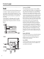
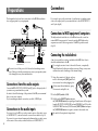
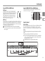
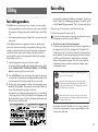
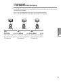
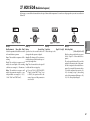
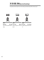
1
E 1 ii Precautions Location Using the unit in the following locations can result in a malfunction. • In direct sunlight • Locations of extreme temperature or humidity • Excessively dusty or dirty locations • Locations of excessive vibration • Close to magnetic fields Power supply Please connect the designated AC adapter to an AC outlet of the correct voltage. Do not connect it to an AC outlet of voltage other than that for which your unit is intended. Interference with other electrical devices Radios and televisions placed nearby may experience reception interference. Operate this unit at a suitable distance from radios and televisions. Handling To avoid breakage, do not apply excessive force to the switches or controls. Care If the exterior becomes dirty, wipe it with a clean, dry cloth. Do not use liquid cleaners such as benzene or thinner, or cleaning compounds or flammable polishes. Keep this manual After reading this manual, please keep it for later reference. Keeping foreign matter out of your equipment Never set any container with liquid in it near this equipment. If liquid gets into the equipment, it could cause a breakdown, fire, or electrical shock. Be careful not to let metal objects get into the equipment. If something does slip into the equipment, unplug the AC adapter from the wall outlet. Then contact your nearest Korg dealer or the store where the equipment was purchased. Data handling THE FCC REGULATION WARNING (for U.S.A.) This equipment has been tested and found to comply with the limits for a Class B digital device, pursuant to Part 15 of the FCC Rules. These limits are designed to provide reasonable protection against harmful interference in a residential installation. This equipment generates, uses, and can radiate radio frequency energy and, if not installed and used in accordance with the instructions, may cause harmful interference to radio communications. However, there is no guarantee that interference will not occur in a particular installation. If this equipment does cause harmful interference to radio or television reception, which can be determined by turning the equipment off and on, the user is encouraged to try to correct the interference by one or more of the following measures: • Reorient or relocate the receiving antenna. • Increase the separation between the equipment and receiver. • Connect the equipment into an outlet on a circuit different from that to which the receiver is connected. • Consult the dealer or an experienced radio/TV technician for help. Unauthorized changes or modification to this system can void the user’s authority to operate this equipment. CE mark for European Harmonized Standards CE mark for European Harmonized Standards CE mark which is attached to our company’s products of AC mains operated apparatus until December 31, 1996 means it conforms to EMC Directive (89/336/EEC) and CE mark Directive (93/68/EEC). And, CE mark which is attached after January 1, 1997 means it conforms to EMC Directive (89/336/ EEC), CE mark Directive (93/68/EEC) and Low Voltage Directive (73/23/EEC). Also, CE mark which is attached to our company’s products of Battery operated apparatus means it conforms to EMC Directive (89/336/EEC) and CE mark Directive (93/68/EEC). Unexpected malfunctions can result in the loss of memory contents. Please be sure to save important data on an external data filer (storage device). Korg cannot accept any responsibility for any loss or damage which you may incur as a result of data loss. Printing conventions in this manual Parameters “ ” Parameters are enclosed in “double quotation marks.” Symbols , , These symbols respectively indicate cautions, advice, and MIDIrelated explanations. MIDI-related explanations CC# is used as an abbreviation for Control Change Number. In MIDI-related explanations, numbers enclosed in square brackets [ ] are in hexadecimal notation. Display indications The numerical values of various parameters appearing in this manual are only for explanatory purposes. They may not necessary match what appears in the display of your R3. Knob positions and parameters Knob positions and parameter values appearing in this manual are approximations. There may be slight discrepancies between knob positions and parameter values. * Company names, product names, and names of formats etc. are the trademarks or registered trademarks of their respective owners. iii Thank you for purchasing the Korg R3 synthesizer/vocoder. To ensure trouble-free enjoyment, please read this manual carefully and use the product correctly. Introduction.......................................................... 1 Main Features ..................................................................................... 1 The structure of a program .................................................................. 2 Synthesizer ..................................................................................................... 2 Vocoder ........................................................................................................... 4 Front and rear panel ........................................................................... 5 Front panel ..................................................................................................... 5 Rear panel ...................................................................................................... 7 Preparations ........................................................ 8 Connections ......................................................................................... 8 Connections from the audio outputs ......................................................... 8 Connections to the audio inputs ................................................................ 8 Connections to MIDI equipment/computers .......................................... 8 Connecting the included mic ...................................................................... 8 Connecting the pedal ................................................................................... 9 Turning the power on ......................................................................... 10 1. The power supply ................................................................................... 10 2. Turning the power on ............................................................................ 10 3. Turning the power off ............................................................................ 10 Quick Start......................................................... 11 Demo songs ...................................................................................... 11 Listening to the demo songs ..................................................................... 11 Synth programs ................................................................................. 12 1. Selecting and playing a program ......................................................... 12 2. Modifying the sound .............................................................................. 12 iv Table of contents Vocoder programs ............................................................................. 14 1. Playing a vocoder program ................................................................... 14 2. Modifying the sound .............................................................................. 14 Arpeggiator ...................................................................................... 15 Using the arpeggiator ................................................................................ 15 Modulation Sequence ........................................................................ 16 1. Playing back a modulation sequence .................................................. 16 2. Recording a modulation sequence ....................................................... 16 Formant Motion ................................................................................. 18 1. What is a Formant Motion? ................................................................... 18 2. Recording formant motion data ........................................................... 18 Editing ............................................................... 19 Basic editing ...................................................................................... 19 Basic editing procedures ............................................................................ 19 Editing each timbre .................................................................................... 20 Editing a vocoder program ....................................................................... 21 Editing the arpeggiator .............................................................................. 22 How to read the pages for each section .................................................. 22 Table of Contents Timbre Parameters ............................................. 23 Arpeggio parameters ......................................... 51 1. VOICE ........................................................................................... 23 Front Panel Arpeggio Parameters ...................................................... 51 2. UNISON ........................................................................................ 24 32. ARPEGGIATOR-A ......................................................................... 52 3. PITCH-A ........................................................................................ 25 33. ARPEGGIATOR-B ......................................................................... 53 4. PITCH-B ......................................................................................... 26 5. OSC1 (Oscillator 1) ........................................................................ 27 Vocoder parameters ........................................... 54 6. OSC2 (Oscillator 2) ........................................................................ 30 Front panel vocoder parameters ........................................................ 54 7. MIXER ........................................................................................... 31 34. CARRIER ...................................................................................... 55 8. FILTER1-A ...................................................................................... 32 35. MODULATOR-A ........................................................................... 56 9. FILTER1-B ....................................................................................... 34 36. MODULATOR-B ............................................................................ 57 10. FILTER2-A .................................................................................... 35 37. FILTER .......................................................................................... 58 11. FILTER2-B .................................................................................... 36 38. FILTER/AMP ................................................................................. 59 12. AMP (Amplifier) ........................................................................... 37 39. CH LEVEL /PAN (Channel Level/Channel Panpot) ......................... 60 13. DRIVE/WS (Drive/Wave Shape) ................................................... 38 14. EG1 ............................................................................................ 40 Overall settings (GLOBAL) ................................... 61 15. EG2 ............................................................................................ 41 16. EG3 ............................................................................................ 42 GLOBAL structure .............................................................................. 61 Overview ...................................................................................................... 61 17. EG VELO INT (EG Level Velocity Intensity) ..................................... 43 40. GLOBAL-A ................................................................................... 62 18. LFO 1, 19. LFO 2 ......................................................................... 44 41. GLOBAL-B ................................................................................... 63 20. PATCH 1, 21. PATCH 2, 22. PATCH 3, 23. PATCH 4, 24. PATCH 5, 25. PATCH 6 ................................................................. 45 MIDI parameters ................................................ 64 26. MOD SEQ-A (Modulation Sequencer) ........................................... 46 27. MOD SEQ-B (Modulation Sequence) ............................................. 47 28. EQ (Equalizer) ............................................................................. 48 29. INSERT FX1, 30 INSERT FX2 ......................................................... 49 31. MASTER FX .................................................................................. 50 Using the R3 with other MIDI devices (MIDI) ....................................... 64 Overview ...................................................................................................... 64 Connecting MIDI devices/computers .................................................... 64 MIDI-related settings ................................................................................. 65 42. MIDI ............................................................................................ 68 43. MIDI FILTER .................................................................................. 70 44. MIDI CC# MAP (MIDI Control Change No. Map) ........................... 71 45. PATCH SOURCE ........................................................................... 72 v Table of Contents Pedal/Switch parameters.................................... 73 46. PEDAL/SW .................................................................................. 73 Saving Data ....................................................... 74 Saving your edited settings ................................................................ 74 Saving a program ........................................................................................ 74 Saving GLOBAL, MIDI settings ............................................................... 74 Saving Formant Motion data .................................................................... 74 SHIFT functions ................................................... 75 Copying and exchanging timbres/ Initializing a program .................. 75 Initializing Vocoder Parameters.......................................................... 76 Copy Effect ........................................................................................ 76 Data dump ........................................................................................ 77 Restoring the factory settings ............................................................. 78 Write protect setting .......................................................................... 78 Other SHIFT key functions .................................................................. 79 Index ................................................................. 81 Voice Name List .................................................. 83 Trouble shooting ................................................. 86 Specifications and options................................... 87 vi Introduction Main Features 1. MMT (Multi Modeling Technology) synthesis engine 6. Modulation Sequencers In addition to traditional analog synthesizer waveforms, the R3 also provides a wide range of oscillator algorithms, including formant waves, noise, and 64 DWGS (Digital Waveform Generator System) waves. With this rich assortment of oscillator algorithms, your R3 can produce a vast array of sonic variations. Just as step sequencers provide new pitch data to an oscillator over time, the Modulation Sequencers can provide changes in modulation data over time, in a way similar to a classic analog sequencer. Each modulation sequence can be set to provide a new discreet value at each step, or to send out a continuously changing value using the values assigned to each step as a “map”. Modulation Sequences can be recorded in step time or in real time. 2. Advanced Formant Motion vocoding The R3 includes a sixteen band vocoder. In addition to simulating the classic “talking instrument” vocoder sounds of yester-year, you can shift the filter frequencies and adjust the level and panning of each band to create highly original vocoder sounds. There’s also a Formant Motion feature that lets you capture the changing formants - even words -from your voice and reproduce them later as you play the keyboard, without a microphone present! 3. 128 easily editable programs When shipped from the factory, the R3 contains 128 preloaded programs. Banks A–N are loaded with 112 synth programs, while banks O and P contain sixteen vocoder programs. By selecting a page and turning any of the four knobs, you can quickly and intuitively edit these sounds. In addition to detailed editing, these same knobs can be used as Performance Edit controllers to modify the sound as you play. 4. External sound processing Any external audio source can be connected to the R3 via the AUDIO INPUT 1 and 2 jacks, and processed in the same way as the internal waveforms. 7. Built-in EQ and effects to add polish to your sound Each timbre is equipped with two insert effects and a two-band equalizer. Each two-timbre program provides a master effect that lets you add a final touch to your overall sound. Thirty different effect algorithms are available. 8. Arpeggiator You can set the R3’s arpeggiator to produce an arpeggiated pattern of notes by simply holding down a chord. There are six arpeggio types, and you can adjust the gate time, swing amount, and note value of the arpeggiated notes. You can also create rhythmic variations by turning off specific steps of the arpeggio pattern. 9. Editor/Librarian software By connecting the R3 to your computer, you can use the Editor/Librarian software (included free) to edit all of the R3’s parameters from your computer. The R3 is also equipped with USB/MIDI, eliminating the need for a MIDI interface. 5. Virtual Patches Modulators and controllers such as the filter EG, amp EG, LFO 1/2, keyboard tracking, and the modulation wheel can be routed to control parameters such as pitch, cutoff, and amp. This virtual patching mimics the patching versatility of modular analog synthesizers (without using actual patch cables) to provide more creative flexibility. 1 The structure of a program ○ ○ ○ ○ ○ ○ ○ ○ ○ ○ ○ ○ ○ ○ ○ ○ ○ ○ ○ ○ ○ ○ ○ ○ ○ ○ ○ ○ ○ ○ ○ ○ ○ ○ ○ ○ ○ ○ Synthesizer Each of the R3’s programs consists of two timbres, a master effect, and an arpeggiator (Figure 0-1). Figure 0-1 Audio Input 1 Audio Input 2 Timbre 1 Synth EQ Insert FX 1/2 Timbre 2 Synth EQ Insert FX 1/2 Master FX OUTPUT (L/MONO, R) Arpeggiator Voice / Unison / Pitch These sections provides additional parameters relating to the oscillators, such as trigger mode, unison stacking, transpose, portamento, bend range, etc. For die-hard analog fans, this is also where you can find the Analog Tune parameter, used to introduce simulated oscillator drift. Synth Filter Routing= Individual OSC1 FILTER1 AUDIO INPUT 1, 2 OSC MOD MIXER Drive/WS Position = PreAmp DRIVE/WS FILTER2 AMP To EQ PAN OSC2 EG1 KBD TRACK NOISE LFO1 Free Assign MOD SEQUENCER LFO2 EG1 EG2 EG3 MIDI 1–3 VIRTUAL PATCH KBD Track Velocity Pitch Bend Mod Wheel Free Assign Timbre 1/2 In the top diagram, you can see that each timbre consists of a Synth, an EQ, and two Insert Effects (IFX). The lower diagram shows the structure of each timbre’s synth section. Oscillator (OSC1/OSC2/NOISE) There are three Oscillator sources; Oscillator 1, Oscillator 2, and the noise generator. Oscillator 1 (OSC1) lets you choose from seven different oscillator algorithms. These include conventional analog synthesizer waveforms, DWGS waveforms, formant waves, noise, plus an external 2 audio signal. Oscillator 2 (OSC2) lets you choose from four different oscillator waves - sine, triangle, square, and sawtooth. The noise generator (NOISE) produces white noise. You can use this for a variety of sound shaping situations, such as adding breath noise for a wind instrument sound, or as part of a special effect sound. Modulation such as crossmodulation, unison, and VPM (Variable Phase Modulation) can be applied to the analog synthesizer waveforms of Oscillator 1. Oscillator 2 can be used as the modulating oscillator for the sync modulation (SYNC) or ring modulation (RING) that are such classic analog synthesizer techniques. The best elements of SYNC and RING modulation can be combined using a third option: RING SYNC. Mixer (MIXER) The mixer adjusts the volume levels of oscillator 1 (OSC1), oscillator 2 (OSC2), and the noise generator (NOISE), and sends the combined signal to the filter (FILTER). Filter (FILTER1/FILTER2) The filter section consists of two multi-mode, resonant filters. The two filters can be routed in series or parallel, or even side by side in a "one oscillator per filter" arrangement. The filters adjust the tone of the sound coming from the oscillators by boosting or cutting specific frequency regions. Filter settings will have a major impact on the sound. By default, envelope generator 1 (EG1) is set to vary the cutoff frequency of the filters over time. Amp (AMP) Traditionally, the amp section controls the output volume (AMP) and the panning (PAN), or the position in the stereo field. By default, envelope generator 2 (EG2) is set to vary the volume level over time. Drive/Wave Shape (DRIVE/WS) The R3 provides additional features to add more tonal complexity and “edge” to the sound - including Drive, Wave Shape control (DRIVE/WS). The structure of a program Envelope generators (EG1/EG2/EG3) Envelope generators (EG) are used to apply time-varying change to the sound parameters. Each EG consists of four parameters: attack time (ATTACK), decay time (DECAY), sustain level (SUSTAIN), and release time (RELEASE). Each timbre contains three of these EGs. EG1 is assigned to control the filter cutoff frequency, and EG2 is assigned to control the volume of the amp. You can also use virtual patching (VIRTUAL PATCH) to assign these EGs as envelope sources for other parameters. Master effect (MFX) LFO section (LFO1/LFO2) LFO (Low Frequency Oscillator) is used to apply cyclic change to the sound parameters. Each timbre contains two LFOs, and for each LFO you can choose one of five waveforms. By default, LFO1 is assigned to oscillator 1’s analog algorithms as the knob labelled “OSCCtr2”, and LFO2 is assigned to the modulation wheel. You can also make virtual patch settings (VIRTUAL PATCH) to assign the LFOs as modulation sources for other parameters. You can apply the arpeggiator to a timbre. If the program uses two timbres, you can apply the arpeggiator to either or both timbres. This is a step arpeggiator with six types of arpeggios. Each program contains one master effect. You can use this to apply a reverb or delay effect to the overall combined sound of the program including the processing applied by the insert effects of each timbre, adding the final touch to the complete program. You can choose from thirty different effect types, and 128 editable effect programs. Arpeggiator Virtual Patch (VIRTUAL PATCH) The virtual patch section lets you freely assign modulation sources to modulate-able parameters, giving you even more flexibility for creating sounds. You can make six virtual patch assignments in each timbre. Modulation Sequencer (MOD SEQUENCER) Using a modulation sequencer, you can apply up to sixteen discrete values (steps) to a modulate-able parameter over time, in a manner similar to vintage analog synthesizers. The modulation sequence can play once, repeat, loop front to back, etc. - providing movement and complexity to the sound. The value can change abruptly at each step, or it can smoothly transition from value to value. The value of each step can be set using the front panel knobs, or by using the Motion Rec function to record knob movements (changes in parameter values) in realtime. Equalizer (EQ) and Insert Effects (INSERT FX1/FX2) Each timbre is equipped with a two-band Equalizer to further control the overall tone. In addition, each timbre also possesses two insert effects. Thirty different effect types are available, and their 128 editable effect program locations to save your favorites. Certain effects can by synced to the tempo of the internal clock that is running the arpeggiator, or to an external MIDI clock. BPM Sync effects can be conveniently set as note values (Half-note, quarter-note, etc.). 3 The structure of a program ○ ○ ○ ○ ○ ○ ○ ○ ○ ○ ○ ○ ○ ○ ○ ○ ○ ○ ○ ○ ○ ○ ○ ○ ○ ○ ○ ○ ○ ○ ○ ○ ○ ○ ○ ○ ○ ○ Vocoder A vocoder is a device that analyzes the character (the frequency response of each band) of a “modulator” signal (typically a human voice from a mic), and applies a filter with the analyzed characteristics to the “carrier” signal (typically a waveform produced by an oscillator), imposing a vocal character on that waveform, and making it seem as though the instrument is talking. As shown in figure 0-2, a vocoder program consists of two signals; a carrier (the signal that is modified) and a modulator (the signal that modulates the carrier). These signals are routed to the vocoder section. Figure 0-2 Audio In 1 Audio In 2 Synth EQ Vocoder Sw= ON Timbre 1 Carrier INSERT FX1/2 Vocoder Modulator Vocoder Sw= ON & Modulator AudioSrc = Timbre2 Synth Timbre 2 EQ INSERT FX1/2 MASTER FX OUTPUT (L/MONO, R) Vocoder Band1 Audio Input 1 Timbre 2 Modulator ANALYSIS FILTER E.F. Sens ENVELOPE FOLLOWER LEVEL Resonance Audio Input 2 Carrier LEVEL Fc Offset Formant shift 4 FORMANT MOTION DATA To Timbre 1 EQ Level1…16 Pan1…16 Timbre 1 Direct Level HPF Level Formant Motion On/Off SYNTHESIS FILTER Modulator (MODULATOR) Most commonly, you will input your voice as the modulator, but interesting results can also be obtained by inputting a rhythm sound as the modulator waveform. You can use an Audio Input1, Timbre2 or a Formant motion data as the modulator. Carrier (CARRIER) A sawtooth wave (SAW) or other waveform rich in overtones is the best choice for the carrier. As the carrier, you can use a combination of two sources (Timbre1 and Audio Input2). HPF Band16 Vocoder section (VOCODER) The vocoder divides the audio spectrum into “bands”. In the R3, the vocoder uses 16 bands. There are actually two sets of 16 bands; the first is used to analyze the tonal characteristics of one sound (the Modulator), and the second set is used to apply the same characteristics to another sound (the Carrier). Each analysis band contains a bandpass filter and an envelope follower. Each synthesis band contains a band pass filter whose output is controlled by the matching envelope follower in the analysis band. The modulator’s audio signal is sent through the sixteen bandpass filters (the analysis filters), and the envelope follower detects the volume envelope (change over time) for each of these frequency bands. The carrier’s audio signal is sent through the other set of sixteen bandpass filters (the synthesis filters), and the envelope detected from each analysis filter is applied to each synthesis filter to modulate the sound, producing the impression that the carrier sound is “talking” (the typical vocoder effect). You can use the “FrmntSft (formant shift)” and “FcOffset (Cutoff)” parameters to shift the frequencies of the carrier bandpass filters. This will raise or lower the frequency response while preserving the character of the modulator, creating major changes in the sound. Front and rear panel ○ ○ ○ ○ ○ ○ ○ ○ ○ ○ ○ ○ ○ ○ ○ ○ ○ ○ ○ ○ ○ ○ ○ ○ ○ ○ ○ ○ ○ ○ ○ ○ ○ ○ ○ ○ ○ ○ Front panel AUDIO INPUT1 [MIC] jack Connect a mic to this input. Vocoder-type programs use the audio signal from this mic as the modulator. The [MIC] switch specifies whether this jack or the rear panel [AUDIO INPUT 1] jack will be used. [MIC] switch Selects the audio input source for AUDIO INPUT 1. Select the XLR setting if you're using the front panel [MIC] jack. Select the REAR setting if you're using the rear panel [AUDIO INPUT 1] jack. [AUDIO INPUT 2] knob Adjusts the input level from the rear panel [AUDIO INPUT 2] jack. The LED will light when there is an input signal, and will light red if the input is overloaded. [TEMPO] knob Adjusts the tempo (speed) of the arpeggio, LFO, or effect delay. The LED at the right will blink in synchronization with the tempo. TIMBRE SELECT [TIMBRE1] (TIMBRE1 SOLO), [TIMBRE2] (TIMBRE 2 SOLO) buttons Select the timbre(s) that you want to play or edit. You can solo each timbre by holding down the [SHIFT] button and pressing one of these buttons. [VOCODER] (AUDIO IN THRU) button Switches the vocoder on/off (☞p.55). OFF (dark): Vocoder is off. ON (lit): Vocoder is on. EDIT (blinking): Vocoder parameters can be edited. AUDIO IN THRU function If you hold down the [SHIFT] button and press this button, the signal from the [AUDIO INPUT 1] (or MIC) jack and the [AUDIO INPUT 2] jack will be passed through to the OUTPUT [L/MONO] and [R] jacks (☞p.79). [AUDIO INPUT 1] knob Adjusts the input level from the front panel [MIC] jack and the rear panel [AUDIO INPUT 1]. The LED will light when there is an input signal, and will light red if the input is overloaded. PROGRAM SELECT [1] [2] [3] [4] [5] [6] [7] [8] buttons Select a program number within the bank selected by the [BANK SELECT] dial. (The selected button will light.) You can also use these buttons to turn the eight steps of an arpeggio on/off to vary the arpeggio performance. (☞p.15) In addition, you can hold down the [SHIFT] button and press one of these buttons to access the corresponding utility function (☞p.75 SHIFT function). [MASTER VOLUME] knob Adjusts the output volume from the OUTPUT jacks (L/MONO, R) and headphone jack OCTAVE [UP] [DOWN] buttons Shift the pitch assigned to the keyboard in one-octave steps over a range of ±3 octaves. [PITCH] wheel Controls the pitch. [MOD] wheel Controls the depth of modulation (cyclic change). ARPEGGIATOR [ON/OFF] (DEMO) button Switches the arpeggiator on/off (the button is lit when on). You can initiate demo playback by holding down the [SHIFT] button and pressing this button. ARPEGGIATOR [LATCH] (CALIBRATION) button Specifies how the arpeggiator behaves when you release the keyboard. You can execute the foot pedal calibration function by holding down the [SHIFT] button and pressing this button. [BANK SELECT] dial Selects the program bank (A–P). When the R3 is shipped from the factory, sounds are organized in these banks by category. 5 Front and rear panel [WRITE] button Saves the program or global settings you’ve edited (☞p.74). [SHIFT] button You can execute SHIFT functions (various utilities) by holding down this button and pressing another button (☞p.75). [EXIT] button When you’re editing, this button finalizes the settings and returns you to Play mode. When you’re using a SHIFT function, this button cancels execution of the function and returns you to Play mode (☞p.75). MOD SEQ/FORMANT MOTION [ON/OFF] button If you’ve selected timbre 1 or 2 in the TIMBRE SELECT section, pressing this button to make it light (on) will play back the recorded modulation sequence data (☞p.16). When you’re editing the vocoder, pressing this button to make it light (on) will play back the formant motion data. This lets you produce a vocoder effect without inputting an audio signal from an external source (☞p.18). If this button is dark (off), a vocoder effect will be produced using an external audio signal. By holding down the [SHIFT] button and pressing this button, you can specify the functions that the [1]–[4] knobs will have in Play mode (☞p.75 “SHIFT functions”). Sub-displays These show parameter names or values for the selected program (Play mode) or edit page (Edit mode). [1] [2] [3] [4] knobs Use these knobs for performance editing in Play mode, or to edit the parameters in the various pages of Edit mode (☞p.19). [PAGE] dial By turning this dial while in Play mode, you can enter Edit mode and select a page to edit (☞p.19). When using a SHIFT function, use this dial to specify a parameter or value (☞p.75). MOD SEQ/FORMANT MOTION [REC] button When you’re editing a timbre, this button takes you to Modulation Sequence recording mode (☞p.16). When you’re editing the vocoder, this button takes you to Formant Motion Data recording mode (☞p.18). 6 Main display In Play mode, this shows information about the currently selected program. In Edit mode, this shows the page name you’re editing. In other cases, this display shows the current setting or various messages. ORIGINAL VALUE LED In Edit mode, this will light if the value of the parameter you’re editing matches the value stored in the program (☞p.20). Front and rear panel ○ ○ ○ ○ ○ ○ ○ ○ ○ ○ ○ ○ ○ ○ ○ ○ ○ ○ ○ ○ ○ ○ ○ ○ ○ ○ ○ ○ ○ ○ ○ ○ ○ ○ ○ ○ ○ ○ Rear panel ASSIGNABLE You can connect a foot switch and foot pedal to these jacks. [SWITCH] jack Connect a foot switch or damper pedal to this jack. [PEDAL] jack Connect a foot pedal to this jack. [Contrast knob] Adjusts the contrast of the main display and the sub-displays. The readability of the displays will depend on your viewing angle, so you should adjust the contrast as needed for best visibility. [POWER/STANDBY] switch Turns the power on or off. (☞p.10) DC12V IN connector Connect the included AC adaptor to this connector. Connect the AC adaptor to the R3 before you plug the adaptor into an AC outlet. [USB] connector Connect this to your computer so that MIDI data can be transferred between the computer and the R3. This also lets you use the included Editor/Librarian software to edit the R3’s parameters. [AUDIO INPUT 2] jack For synthesizer programs, you can connect an external synthesizer or audio device to this jack and use its audio signal as the oscillator 1 waveform. For vocoder programs, you can use this signal as the external carrier of the vocoder. Use the front panel [AUDIO INPUT 2] knob to control the input level. OUTPUT [L/MONO], [R] jacks Connect your powered monitors, stereo amp, mixer, or multi-track recorder to these jacks. Use the L/MONO jack for monaural connection. [PHONES] jack Connect your headphones (stereo 1/4" plug) to this jack. MIDI Use these connectors to connect external MIDI devices to the R3 so that MIDI data can be transferred. [MIDI IN] connector This connector receives MIDI data. [MIDI OUT] connector This connector transmits MIDI data. [MIDI THRU] connector Incoming MIDI data is retransmitted without change from this connector. Use this when you want to pass the same stream of MIDI data to multiple MIDI devices. [AUDIO INPUT 1] jack For synthesizer programs, you can connect an external sequencer, audio device, or 1/4" plug microphone to this jack, and use the input signal as the oscillator 1 waveform. For vocoder programs, you can use this signal as the modulator. Use the front panel [AUDIO INPUT 1] knob and [MIC] switch to control the input level. If you want to use this jack, you must set the front panel [MIC] switch to the REAR position. If the [MIC] switch is set to XLR, the front panel [MIC] jack will be used rather than this jack. [MIC/LINE] switch Set this to the MIC position if you’ve connected a mic to the AUDIO INPUT 1, or to the LINE position if you’ve connected an external synthesizer or audio device. In some cases, noise may occur when you operate this switch. Turn the [MASTER VOLUME] knob all the way toward the left before you operate the switch. 7 Connections Preparations The diagram below shows basic connections for the R3. Make substitutions as appropriate for your equipment. Included mic If you want to process the waveform of a synthesizer or sampler, connect a mic or the output jack of your external device to the AUDIO INPUT 1 and 2 jacks (☞p.29). ○ ○ ○ ○ ○ ○ ○ ○ ○ ○ ○ ○ ○ ○ ○ ○ ○ ○ ○ ○ ○ ○ ○ ○ ○ ○ ○ ○ ○ ○ ○ ○ ○ ○ ○ ○ ○ ○ Connections to MIDI equipment/computers The keyboard, and controllers etc. of the R3 can be used to control an external MIDI tone generator. Conversely, another MIDI keyboard or sequencer can control the tone generator of the R3 to produce sound. (☞p.64) Phones AC adapter (included) MIDI IN MIDI OUT ○ ○ ○ ○ ○ ○ ○ ○ ○ ○ ○ ○ ○ ○ ○ ○ ○ ○ ○ ○ ○ ○ ○ ○ ○ ○ ○ ○ ○ ○ ○ ○ ○ ○ ○ ○ ○ ○ Connecting the included mic Connect to an AC outlet MIDI keyboard, tone generator module, rhythm machine etc. Powered monitors, etc. Be sure to turn off the power of all devices before making connections. Failing to take this precaution may cause your speaker system to be damaged, or may cause malfunctions. A mic for use with the vocoder is included with the R3. Here's how to attach the included mic to the R3. Do not apply excessive force to the neck of the mic, or repeatedly bend it back and forth any more than necessary. Doing so may cause malfunctions such as breakage of the internal wiring. 1 Grasp the connector of the mic and con○ ○ ○ ○ ○ ○ ○ ○ ○ ○ ○ ○ ○ ○ ○ ○ ○ ○ ○ ○ ○ ○ ○ ○ ○ ○ ○ ○ ○ ○ ○ ○ ○ ○ ○ ○ ○ ○ Connections from the audio outputs Connect the R3’s OUTPUT [L/MONO] and [R] jacks to the input jacks of your mixer or powered monitor system. In order to take full advantage of the potential of the R3, we recommend that you use stereo outputs. If you are making monaural connections, use the L/MONO jack. ○ ○ ○ ○ ○ ○ ○ ○ ○ ○ ○ ○ ○ ○ ○ ○ ○ ○ ○ ○ ○ ○ ○ ○ ○ ○ ○ ○ ○ ○ ○ ○ ○ ○ ○ ○ ○ ○ Connections to the audio inputs If you want to use the R3 as a vocoder, connect a mic or other audio source to AUDIO INPUT 1, and use that audio source as the modulator (☞p.14). If you want to use an external sequencer, rhythm machine, or audio source as the carrier of the vocoder, connect that device to AUDIO INPUT 2. 8 nect it to the front panel [MIC] jack. Don’t use excessive force when plugging it in. 1 2 To disconnect the included mic, grasp the connector and pull it out. 2 Set the [MIC] switch to XLR. 3 Hold down the [SHIFT] button and press the [VOCODER] button; the input signal from the mic will be output from the OUTPUT [L/MONO] [R] jack and [PHONES] jack. (This is the AUDIO IN THRU function.) Hold down the [SHIFT] button and press the [VOCODER] button once again to return to the normal state. Be careful of the input and output levels. Connections ○ ○ ○ ○ ○ ○ ○ ○ ○ ○ ○ ○ ○ ○ ○ ○ ○ ○ ○ ○ ○ ○ ○ ○ ○ ○ ○ ○ ○ ○ ○ ○ ○ ○ ○ ○ ○ ○ Connecting the pedal ASSIGNABLE PEDAL jack By connecting a pedal such as the Korg EXP-2 or XVP-10 to this jack. You can send control messages such as breath control, volume, pan, expression, etc. while keeping your hands free for performing. The function controlled by the pedal can be specified in the 46. Pedal/Sw page “A.Pedal.” The factory default setting for the assignable pedal is Expression (Exp Pedal). (☞p.73) ASSIGNABLE SWITCH jack This jack is used for a switch type of pedal such as the Korg PS-1 pedal switch or Korg DS-1H damper pedal. The foot switch can be used for various functions including switching programs, changing octaves, or turning portamento or the arpeggiator on/off. The pedal can be set to act as a momentary pedal, or as a toggle type of switch pedal. The function controlled by the switch can be specified in the 46. Pedal/Sw page “A.SwFunc.” The factory default setting for the assignable switch is Damper. (☞ p.73) 9 Turning the power on ○ ○ ○ ○ ○ ○ ○ ○ ○ ○ ○ ○ ○ ○ ○ ○ ○ ○ ○ ○ ○ ○ ○ ○ ○ ○ ○ ○ ○ ○ ○ ○ ○ ○ ○ ○ ○ ○ ○ ○ ○ ○ ○ ○ ○ ○ ○ ○ ○ ○ ○ ○ ○ ○ ○ ○ ○ ○ ○ ○ ○ ○ ○ ○ ○ ○ ○ ○ ○ ○ ○ ○ ○ ○ ○ ○ 1. The power supply 3. Turning the power off Before you connect the power supply, make sure that the [POWER/ STANDBY] switch is turned off (i.e., in the outward position). After saving any necessary data (such as a program you have edited) turn the power off using the reverse order of the power-on procedure. Connecting the AC adaptor Firmly insert the plug of the included AC adaptor into the jack. Then connect the AC adaptor to an AC outlet. Never use any AC adaptor other than the included one. ○ ○ ○ ○ ○ ○ ○ ○ ○ ○ ○ ○ ○ ○ ○ ○ ○ ○ ○ ○ ○ ○ ○ ○ ○ ○ ○ ○ ○ ○ ○ ○ ○ ○ ○ ○ ○ ○ 2. Turning the power on Before you turn on the R3’s power, you should lower the level of your monitor system or other connected output device. 1 Turn the R3’s [MASTER VOLUME] knob all the way toward the left. 2 Press the [POWER/STANDBY] switch to turn on the power. The display will indicate the program number and name. 3 Turn the R3’s [MASTER VOLUME] knob toward the right to an appropriate position. 4 Adjust the volume of your external output device. 2 1, 4 10 Never turn the power off while data is being saved (i.e., while Write is executing). Doing so may damage the internal data. Demo songs Quick Start ○ ○ ○ ○ ○ ○ ○ ○ ○ ○ ○ ○ ○ ○ ○ ○ ○ ○ ○ ○ ○ ○ ○ ○ ○ ○ ○ ○ ○ ○ ○ ○ ○ ○ ○ ○ ○ ○ Listening to the demo songs The R3 contains several demo songs that take advantage of the rich sounds and expressive potential of the instrument. 1 To listen to the demo songs, hold down the [SHIFT] button and press the ARPEGGIATOR [ON/OFF] button. The demo will begin playing. the PROGRAM NUMBER button will light and the ARPEGGIATOR [ON/OFF] button will blink. 2 To switch demo songs during playback, press the PROGRAM NUMBER [1]–[8] buttons. 3 When you press the [SHIFT] button, demo playback will stop. The R3 will return to normal playing mode. 1 1 3 2 11 Synth programs ○ ○ ○ ○ ○ ○ ○ ○ ○ ○ ○ ○ ○ ○ ○ ○ ○ ○ ○ ○ ○ ○ ○ ○ ○ ○ ○ ○ ○ ○ ○ ○ ○ ○ ○ ○ ○ ○ ○ ○ ○ ○ ○ ○ ○ ○ ○ ○ ○ ○ ○ ○ ○ ○ ○ ○ ○ ○ ○ ○ ○ ○ ○ ○ ○ ○ ○ ○ ○ ○ ○ ○ ○ ○ ○ ○ 1. Selecting and playing a program 2. Modifying the sound The R3 contains 128 programs. For easy selection, the programs are arranged into 16 banks (A-P). Each bank contains eight programs. To select different programs, use the PROGRAM SELECT knob and the PROGRAM NUMBER buttons. As an example, here’s how to select program “D–4 Trancer”. On the R3, you can modify the sound to add expression to your performance by turning the knobs [1]–[4], by moving the [PITCH] or [MOD] wheels, or by the way that you play the keyboard. Try out these various ways to modify the selected program. 1 Turn the PROGRAM SELECT knob to the “D–POLY SYNTH” posi- In the R3’s normal state (when the main display is showing the program name), you can use knobs [1]–[4] to control specific parameters of the selected program in realtime. This is referred to as Performance Editing. The Performance Edit function of each knob can be set individually for each “section” (Timbre 1, Timbre 2, and Vocoder). See page 80 for more information. With the factory preloaded data, the Performance Edit functions for knobs [1]–[4] are generally set to the following parameters. tion. 2 Press the PROGRAM NUMBER [4] button to select the program number. The display will show the name and number of the selected program. The program will change the moment you switch Banks or select a different Number. Timbre 1/Timbre 2: 3 Play the keyboard to listen to the sound. 4 You can use the OCTAVE [UP] or [DOWN] buttons to shift the pitch range of the keyboard. (☞p.13) Program Bank Program Number 1 4 12 Using the Performance Edit function 2 Knob [1]: Filter1 Cutoff Frequency (Cutoff1) Knob [2]: Filter1 Resonance Amount (Reso1) Knob [3]: Filter Envelope (EG1) Intensity (EG1 Int1) Knob [4]: Master Effect Dry/Wet (MFX D/W) Synth programs Using the [PITCH] and [MOD] wheels Using the OCTAVE SHIFT UP and DOWN buttons [PITCH] wheel: Normally this wheel is used for bending the pitch. Pushing the wheel up will bend the pitch up (sharp); pulling the wheel down will bend the pitch down (flat). When the wheel is in the center position, no pitch bend effect is produced. When released, the wheel will return to the center position. You can use these buttons to shift the range of the keyboard, in oneoctave units over a range of +/-3 octaves. Key operation Press DOWN key 0 0 [MOD] wheel: This wheel allows you to manually control the modulation depth. As you push the wheel up, the modulation depth will increase. As you pull the wheel down, the modulation depth will decrease. At the lowest setting, no modulation is applied from this wheel. The [PITCH] and [MOD] wheels can be used as virtual patch sources, they can produce a variety of effects other than described above. (☞p.45) Keyboard range C6–C9 C5–C8 C4–C7 C3–C6 C2–C5 C1–C4 C0–C3 Key LED UP lit red UP lit orange UP lit green dark DOWN lit green DOWN lit orange DOWN lit red Key operation Press UP key Using the keyboard Keyboard Tracking: Keyboard tracking uses the position of the note on the keyboard to affect the sound. Normally, this is used to brighten the sound as you play upward, or to create differences in volume between high and low notes. Velocity: The dynamic strength with which you play the keyboard can affect the sound. Normally, your dynamics will affect the tone and volume. Since velocity and keyboard tracking can be used as a virtual patch source, you can use them to produce a variety of effects other than those described above. (☞p.45) The R3’s keyboard does not generate aftertouch data. Octave Shift settings and note numbers C-1 (0) C0 (12) C1 (24) Middle C on a piano is C4 (MIDI note number 60) C2 (36) C3 (48) C4 (60) C5 (72) C6 (84) C7 (96) -1 octave C8 (108) C9 (120) G9 (127) +3 octaves -2 octaves +2 octaves -3 octaves +1 octave Octave Shift not used C#8 C9 (116) (120) 13 Vocoder programs ○ ○ ○ ○ ○ ○ ○ ○ ○ ○ ○ ○ ○ ○ ○ ○ ○ ○ ○ ○ ○ ○ ○ ○ ○ ○ ○ ○ ○ ○ ○ ○ ○ ○ ○ ○ ○ ○ ○ ○ ○ ○ ○ ○ ○ ○ ○ ○ ○ ○ ○ ○ ○ ○ ○ ○ ○ ○ ○ ○ ○ ○ ○ ○ ○ ○ ○ ○ ○ ○ ○ ○ ○ ○ ○ ○ 1. Playing a vocoder program 2. Modifying the sound A vocoder applies the spectral character of an externally-input voice (the “modulator”) to an oscillator or other sound (the “carrier”), and outputs the result. In the most popular use of a vocoder, you can speak or sing into a mic and play chords on the keyboard, to create the impression that an instrument is speaking or singing. You can also create a variety of interesting effects by using audio signals other than a human voice (such as rhythm sounds). Just as with synth programs, you can modify the sound of a vocoder program by turning the knobs [1]–[4], by moving the [PITCH] and [MOD] wheels, by switching octaves, and by how you play the keyboard. Try using some of these methods to alter the selected program, as described on the preceding pages. With the factory preloaded data, the Performance Edit functions for knobs [1]-[4] are generally set to the following parameters. 1 Turn the [AUDIO INPUT 1] knob all the way to the left, and set the [MIC] switch to XLR. 2 Connect the included mic to the [MIC] connector (☞p.8). 3 Select a vocoder program from bank P (VOCODER). The [VOCODER] button will light. With the factory settings, bank P (VOCODER) contains vocoder programs. 4 Sing or talk into the mic, and turn the [AUDIO INPUT 1] knob up (to the right) as far as you can, without allowing the AUDIO INPUT 1 LED to light red. 1 3 3 1, 4 5 While singing or talking into the mic, play the keyboard. Try speaking or singing different words, and play various chords to hear the vocoder effect. The Formant Motion programs (Bank O) can produce vocoder effect by simply by playing the keyboard; no vocal input is required. These programs use stored formant data to create the vocoder effect. 14 Vocoder : Knob [1]: Formant Offset (FcOffset) Knob [2]: Vocoder Resonance (Vcd Reso) Knob [3]: Envelope Follower Sensitivity (E.F. Sens) Knob [4]: Formant Motion Data Set Number (Frmnt No) Arpeggiator ○ ○ ○ ○ ○ ○ ○ ○ ○ ○ ○ ○ ○ ○ ○ ○ ○ ○ ○ ○ ○ ○ ○ ○ ○ ○ ○ ○ ○ ○ ○ ○ ○ ○ ○ ○ ○ ○ Using the arpeggiator The arpeggiator detects the notes being played on the keyboard, and automatically plays these notes one at a time in a variety of arpeggiated styles. The R3’s arpeggiator provides six arpeggiator patterns, and lets you adjust the duration (gate time) of the arpeggiated notes. The R3 also allows you to specify the on/off status of each note in the chord for as many as eight steps, letting you create an even wider range of arpeggio patterns. Turning individual steps on and off to vary the arpeggio 6 With the [PAGE] dial set to the 32. Arpeggiator-A or 33. Arpeggiator-B page from the previous step, the PROGRAM NUMBER [1]–[8] buttons will act as arpeggiator step on/off buttons, and will be lit (the “on” state) for the number of valid steps. By turning a step off (indicated by a blinking button) the corresponding step will change to a rest, and the resulting arpeggio will change (see the diagram below). The on/off status off each step can be set individually, allowing even more rhythmic possibilities. TYPE: UP LAST STEP: 8 When you play the chord shown above on the keyboard, the notes will be sounded as shown at the right. (TYPE: UP) 1 Select a program. (☞p.12) You can use the arpeggiator with either a synth program or a vocoder program, but let’s select synth program “K–2 ArpPulse” for this example. 2 Press the ARPEGGIATOR [ON/OFF] button to turn the arpeggiator on (the button will light). 3 Hold down a chord on the keyboard, and the arpeggiator will run. Modifying the arpeggio 7 Press the ARPEGGIATOR [ON/OFF] button to turn the arpeggiator 4 Turn the [PAGE] dial and select either the 32. Arpeggiator-A or the 33. off (the button will go dark). Arpeggiator-B page. 5 Turn the knobs [1]–[4] to adjust the arpeggiator parameters, changing the way that the arpeggiator is sounded. Adjust the tempo by [TEMPO] knob. 5 2 4, 6 15 Modulation Sequence ○ ○ ○ ○ ○ ○ ○ ○ ○ ○ ○ ○ ○ ○ ○ ○ ○ ○ ○ ○ ○ ○ ○ ○ ○ ○ ○ ○ ○ ○ ○ ○ ○ ○ ○ ○ ○ ○ ○ ○ ○ ○ ○ ○ ○ ○ ○ ○ ○ ○ ○ ○ ○ ○ ○ ○ ○ ○ ○ ○ ○ ○ ○ ○ ○ ○ ○ ○ ○ ○ ○ ○ ○ ○ ○ ○ 1. Playing back a modulation sequence 2. Recording a modulation sequence Timbre 1 and timbre 2 provide a “modulation sequence” that can record movement of parameters over time. Let’s use a preset program to hear what a modulation sequence can sound like. Let’s try recording a modulation sequence. 1 Select a synth program. You can use the modulation sequence with a synth program, but let’s select synth program “K–5 RezoBeat” for this example. 2 The modulation sequence will begin playing when you play the keyboard; listen to the result. 3 Turn the modulation sequencer off by pressing the MOD SEQ [ON/ OFF] button (the button will go dark). Recording in Play mode In Play mode you can record the movement of one of the four Performance Edit knobs. 1 Select a synth program. 2 Select a timbre by pressing either the [TIMBRE1] or [TIMBRE2] button. The button for the selected timbre will blink. 3 Turn the modulation sequencer on by pressing the MOD SEQ [ON/ OFF] button. The button will light. 4 Press the MOD SEQ [REC] button to arm the modulation sequencer for recording. 5 While holding down notes on the keyboard, turn the knob that controls the parameter you want to change (one knob; [1], [2], [3], or [4]). Recording will begin the moment you turn the knob. When you’ve reached the last step, the [REC] button will go dark and recording will end. 6 When you play the keyboard, the modulation sequence will begin playing back and will then continue to loop. Listen to the result. The modulation sequencer will record onkè the movement of the knob that initiated recording. Even if you move other knobs after recording has begun, their movements will not be recorded. 2 3 4 5 16 Modulation Sequence Recording in Edit mode In Edit mode you can choose any single parameter that is available for assignment via Knob Assign (SHIFT function) and record a movement for it. 1 Select a synth program. Choose a program that is not saved with a modulation sequence (MOD SEQ [ON/ OFF] button is dark). 2 Select a timbre by pressing either the [TIMBRE1] or [TIMBRE2] button. The button for the selected timbre will blink. 3 Turn the modulation sequencer on by pressing the MOD SEQ [ON/ OFF] button. The button will light. 4 Turn the [PAGE] dial to enter Edit mode and select the page that contains the parameter you want to record. 5 Press the MOD SEQ [REC] button to arm the modulation sequencer for recording. 6 While holding down notes on the keyboard, turn one of the knobs [1]– [4]. Recording will begin the moment you turn the knob. When you’ve reached the last step, the [REC] button will go dark and recording will end. Turning the knob of a parameter that can’t be recorded will not initiate recording. 7 When you play the keyboard, the modulation sequence will begin playing back and will then continue to loop. Listen to the result. 2 3 5 4 6 17 Formant Motion ○ ○ ○ ○ ○ ○ ○ ○ ○ ○ ○ ○ ○ ○ ○ ○ ○ ○ ○ ○ ○ ○ ○ ○ ○ ○ ○ ○ ○ ○ ○ ○ ○ ○ ○ ○ ○ ○ 1. What is a Formant Motion? Basically, the Formant Motion function records and saves the vocoder’s “analysis” of a changing modulator signal. This saved formant motion data can be used to produce vocoder effects without having to vocalize into a mic each time you perform. In its internal memory, the R3 can store sixteen sets of formant motion data, each up to 7.5 seconds long. Vocoder programs (programs for which the [VOCODER] button is lit) can use this data. When the R3 is shipped from the factory, bank O (FORMANT MOTION) contains preloaded programs that use formant motion data. You can select and play programs from this bank to hear the formant motion effect. 8 Speak or sing into the mic. 9 Press the FORMANT MOTION [REC] button to stop recording. Recording will stop automatically when the memory is full. 10 Press the FORMANT MOTION [ON/OFF] button (the button will light). Now you can play the vocoder program using the formant motion data that you just recorded. Saving Here’s how to save the formant motion data you just recorded. 11 Press the [WRITE] button. ○ ○ ○ ○ ○ ○ ○ ○ ○ ○ ○ ○ ○ ○ ○ ○ ○ ○ ○ ○ ○ ○ ○ ○ ○ ○ ○ ○ ○ ○ ○ ○ ○ ○ ○ ○ ○ ○ 2. Recording formant motion data Preparing to record 1 Turn the [AUDIO INPUT 1] knob all the way to the left, and set the [MIC] switch to XLR. 2 Connect the included mic to the [MIC] connector (☞p.8). 3 Select a vocoder program from bank P (VOCODER). The [VOCODER] button will light up. 4 Sing or talk into the mic, and turn the [AUDIO INPUT 1] knob up (to Make sure that the main display indicates “Formant” (i.e., that formant motion data is the data that will be saved). If the display indicates “Program“ or “Global,” use the [PAGE] dial to select Formant. 12 Press the [WRITE] button once again. The main display will indicate the save-destination data number. 13 Use the [PAGE] dial to specify the numbered location (1-16) where you want the formant motion data to be saved. 14 Press the [WRITE] button. The formant motion data will be saved into the numbered location that you specified. the right) as far as you can, without allowing the AUDIO INPUT 1 LED to light red. Recording 5 Press the [VOCODER] button. The button will blink. 6 Press the FORMANT MOTION [REC] button. The button will blink, and you’ll be in the record-ready condition. 7 Press the FORMANT MOTION [REC] button once again. The moment you press the [REC] button, recording will begin and the button will light. 18 5 10 6, 7, 9 11, 12, 14 13 Basic editing Editing ○ ○ ○ ○ ○ ○ ○ ○ ○ ○ ○ ○ ○ ○ ○ ○ ○ ○ ○ ○ ○ ○ ○ ○ ○ ○ ○ ○ ○ ○ ○ ○ ○ ○ ○ ○ ○ ○ Basic editing procedures On the R3 there are two basic ways for you to create your own sound(s). • Select a program that is close to the sound you want to create, and tweak the parameters of that program until it sounds the way you would like it to. • Start from an initialized program (“blank slate”), and create the sound from scratch All of editable parameters are organized into sections, and the parameters in each section are accessed by selecting different edit pages. When creating a sound from scratch, notice that the edit pages are organized in a way that follow the logical order of editing. You can turn the dial to step through these sections in the appropriate order. Broadly speaking, the procedure is as follows. 1 Select the program that you want to start from. (☞p.12) If you want to start from scratch, execute the Initialize operation. (☞p.75) Use the TIMBRE SELECT [TIMBRE1], [TIMBRE2], or [VOCODER] buttons to select the part that you want to edit. 2 Turn the [PAGE] dial to select the edit page that includes the parameter you want to edit. Consider how the current program differs from the sound you have in mind, and select the parameter that you want to edit. 3 Edit the value of the parameters available in the selected page, using knobs [1], [2], [3], and [4]. The parameter controlled by each knob is shown in the sub-display located above each knob. For example if you’re editing a synth program, and you’ve selected the 8. Filt-A page in step 2, knob [1] will adjust the cutoff frequency, knob [2] will adjust the resonance, knob [3] will adjust the filter balance, and knob [4] controls the filter routing. Go ahead and try editing the 15. EG2 page ozBameters “Attack2” and “Decay2” (☞p.41), the 3. Pitch-A page parameter “Portamnt” (☞p.25), or the 29. Insert FX1 page parameter “Type” to hear the result (☞p.49). 4 Repeat steps 2–3 as necessary to create the desired sound. 5 Write the program into memory. (☞p.74) If you select another program or turn the power off before you write the program into memory, your edits will be lost. The difference between Catch and Jump modes In some cases, the parameter values won’t seem to change when you are turning knobs [1]–[4]. This can happen if the “KnobMode” (41. Global-B page) is set to Catch. In the Catch mode, the physical knob must be turned to the position matching the stored value (shown by the LEDs around the perimeter of each knob) before any further editing of that parameter can begin. This allows you to make fine adjustments without any sudden or unnatural-sounding “jumps” occurring in the sound. For example, suppose that before you begin editing, the knob is in the position shown at left. The actual value of this parameter is saved at the position shown by the triangle in the diagram at left. In the Catch mode, the parameter value will not change until you turn the knob all the way to that position. Once the knob reaches the position of the actual saved value, the knob and parameter value will begin changing in tandem, and you can begin to edit the value. On the other hand, if the “KnobMode” is set to Jump, turning the knob will cause the parameter’s value to jump immediately to the actual position of the knob. 2 3 19 Basic editing Returning a parameter to its original value. When editing, you can always return any edited parameter to its original value. Simply rotate the knob assigned to that parameter until the ORIGINAL VALUE LED remains steadily lit. If you select another program or re-select the same program while you are editing, all your edits will be lost, unless you first save any changes you have made. Changes you make to these settings will also be lost if you turn the power off, so you must Write them if you want to keep your changes. ○ ○ ○ ○ ○ ○ ○ ○ ○ ○ ○ ○ ○ ○ ○ ○ ○ ○ ○ ○ ○ ○ ○ ○ ○ ○ ○ ○ ○ ○ ○ ○ ○ ○ ○ ○ ○ ○ Editing each timbre A program can use up to two timbres. A timbre consists of the parameters in pages 1. Voice–30. Ins FX2. In order to edit a parameter, you must first select the timbre that you want to edit (the [TIMBRE 1] or [TIMBRE 2] button will blink). Listening to only one timbre (Solo) For a program that uses both timbres, you can use the Solo function to hear just one timbre. This is convenient when you want to hear just one timbre while you edit. 1 Hold down the [SHIFT] button and press the TIMBRE SELECT [TIMBRE 1] button. Your editing will apply to Timbre 1, and only Timbre 1 will sound. 2 If you want only Timbre 2 to sound, hold down the [SHIFT] button once again and press the TIMBRE SELECT [TIMBRE 2] button. Your editing will apply to Timbre 2, and only Timbre 2 will sound. 3 If you want to cancel the Solo function, hold down the [SHIFT] button and press the blinking [TIMBRE 1] or [TIMBRE 2] button. The Solo state cannot be saved. TIMBRE SELECT SHIFT The 1. Voice page parameters “Mode” apply to the entire program. Using both timbres (Layer) When using two timbres, you can select one of three modes according to your needs, but here we’ll set “Mode” to Layer. ❍ Turn the [PAGE] dial to select the 1. Voice page, and turn knob [1] knob to select Layer. Selecting the timbre to edit Exchanging and copying the settings of the timbres (SHIFT function) If you are editing a program that uses both timbres, here’s how to select the timbre to edit. You can exchange the settings of the two timbres, or copy the timbre settings from another program. (☞p.75) ❍ Press the TIMBRE SELECT [TIMBRE1] button to select timbre 1 as the timbre that you want to edit. TIMBRE SELECT [TIMBRE1] button will light. Your editing will affect the selected timbre. 20 Basic editing ○ ○ ○ ○ ○ ○ ○ ○ ○ ○ ○ ○ ○ ○ ○ ○ ○ ○ ○ ○ ○ ○ ○ ○ ○ ○ ○ ○ ○ ○ ○ ○ ○ ○ ○ ○ ○ ○ Editing a vocoder program Vocoder section The parameters for the sixteen band-pass filters (analysis filters and synthesis filters) and the envelope followers are edited in the 37. Filter– 39. Lvl/Pan pages. Carrier The carrier signal will be processed based on the modulator’s harmonic content, so a good choice for the carrier would be a waveform that is rich in overtones, such as a sawtooth wave or a square wave with a fixed pulse width. You can edit these parameters in the 34. Carrier page. To input a sawtooth wave as the carrier, edit Timbre 1 to set the 5. OSC1 page “Wave” parameter to Saw; then use the Vocoder editing 34. Carrier page “Tmbr1Lvl” parameter to set the output level of Timbre 1. Modulator You will typically use your voice as the modulator input. However, interesting effects can also be obtained by inputting a rhythm sound On the R3, you can choose whether the modulator will be an external input such as a mic or rhythm sound (AUDIO INPUT 1), Timbre 2, or formant motion data. If you choose Timbre 2, the Timbre 2 insert effect output will be input to the modulator of the vocoder (☞Figure v - 1 ). You can edit these parameters in the 35. Modulator-A–36. Modulator-B pages. Selecting the vocoder for editing The procedure for editing the vocoder is essentially the same as when editing a timbre. However, you’ll first need to turn the vocoder function on, and then select the vocoder for editing. 1 Select a vocoder program. 2 Press the [VOCODER] button. The [VOCODER] button will blink, and the vocoder function will be on. The vocoder is also selected for editing. 3 Use the [PAGE] dial to select the 34. Carrier –39. Lev/Pan pages, and use knobs [1]–[4] to edit the vocoder parameters. If you’ve selected the vocoder as the target of your editing, the [PAGE] dial will select only the pages containing the vocoder parameters. 4 Press the [EXIT] button when you’re finished editing. Figure v-1 Audio In 1 Audio In 2 Synth Timbre 1 EQ Vocoder Sw= ON Carrier INSERT FX1/2 Vocoder Modulator Vocoder Sw= ON & Modulator AudioSrc = Timbre2 Timbre 2 Synth EQ INSERT FX1/2 MASTER FX OUTPUT (L/MONO, R) To input your voice as the modulator, turn the front panel FORMANT MOTION [ON/OFF] button off, and set the 35. Modulator-A page “AudioSrc“ parameter to Input1. 21 Basic editing ○ ○ ○ ○ ○ ○ ○ ○ ○ ○ ○ ○ ○ ○ ○ ○ ○ ○ ○ ○ ○ ○ ○ ○ ○ ○ ○ ○ ○ ○ ○ ○ ○ ○ ○ ○ ○ ○ ○ ○ ○ ○ ○ ○ ○ ○ ○ ○ ○ ○ ○ ○ ○ ○ ○ ○ ○ ○ ○ ○ ○ ○ ○ ○ ○ ○ ○ ○ ○ ○ ○ ○ ○ ○ ○ ○ Editing the arpeggiator How to read the pages for each section The R3’s arpeggiator provides six arpeggio types. In addition to selecting an arpeggiator type, you can adjust the duration (gate time) , note value, swing amount, tempo, and other arpeggiator parameters. These arpeggiator settings are adjusted using the 32. Arpeggiator-A page and 33. Arpeggiator-B page parameters. Arpeggiator patterns can be up to eight steps long, and each step can be individually switched on or off (play or mute), providing more rhythmic versatility. (☞Refer to page 15 for more information about arpeggiator steps.) Selecting which timbre(s) will be played by the arpeggiator In a synth program that uses two timbres, you can select which timbre(s) will be played by the arpeggiator. This is specified by Arpeg-A page “Assign” (knob [1]). You can arpeggiate both timbres, only timbre 1 or only timbre 2. Sync’ing the LFO rate and the delay time to the arpeggiator By synchronizing the LFO 1/2 rate to the tempo of the arpeggio, you can apply modulation that follows the arpeggiator tempo. You can also set the time parameter of the delay effect to be a ratio of the tempo, so that the delay time will remain appropriate even if you change the tempo of the arpeggio. This is particularly convenient for live performances. Because the R3’s arpeggiator can be synchronized to an external MIDI sequencer, then in turn you can control the LFO 1/2 rate or the delay time from an external MIDI sequencer. (☞p.67) 22 This is the name of the section. When you have set the [PAGE] dial to the 8. Filter1-A page and would like to see an explanation of the parameters, refer to this page. These are the edit control knobs [1]–[4]. The markings printed around each knob are the values that will be selected when you turn that knob. These positions are approximate. This area lists the parameters that are edited by edit control knobs [1]–[4] when the above section is selected. The range of values for each parameter is given in square brackets [ ]. Explanations of each parameter and its values are given below. A summary of this section is given here. 8. FILTER1-A The filter section changes the tonal character of the oscillators by passing only the desired portion of the sound - either above (Low Pass), below (High-Pass), or centered on (Band Pass) the cutoff frequency. The R3 has two filters (filter 1 and filter 2), and you can change their routing to create more complex filter sounds. The filter 1 parameters are set in the 8. FILTER1-A page and 9. FILTER1-B page. Knob [1] Knob [2] Knob [3] Knob [4] Cutoff1 (Filter1 Cutoff) [0...127] Sets the cutoff frequency. Increasing this value will raise the cutoff frequency. Reso1 (Filter1 Resonance) [0...127] Sets the resonance of the filter. This will emphasize the overtones near the cutoff frequency specified by “Cutoff1,” adding a distinctive character to the sound. Increasing this value will increase the effect. Since movement of the “Cutoff1” knob will affect the overtones that are boosted by resonance, it is best to adjust “Cutoff1” and “Reso1” in conjunction with each other (☞Figure 8-1). Filt1Bal (Filter1 Balance) [LPF24…LPF12…HPF…BPF…THRU] Selects the filter type. Intermediate settings will produce a response that is between the two filter types. Routing1 [Single, Serial, Para, Indiv] Specifies the routing (connection) between filter 1 and filter 2. “Cutoff1” can be varied by time-variant change produced by EG1, by keyboard playing dynamics (velocity), and by note location (keyboard tracking). If the “Cutoff1” value is set too low, the volume may be extremely low, or you may hear no sound at all. Depending on the cutoff frequency or the input audio, increasing this value may cause distortion. LPF12 (–12dB/oct), LPF24 (–24dB/oct): Low Pass Filter (☞p35 “LFP:”). HPF (-12dB/oct): High Pass Filter (☞p35 “HFP:”). BPF (-12dB/oct): Band Pass Filter (☞p35 “BFP:”). THRU: The sound will output directly, without passing through the filter. Single: Only filter 1 is used. Serial: Filter 1 and filter 2 are connected in series (☞Figure 8-2). Parallel: Filter 1 and filter 2 are connected in parallel (☞Figure 8-3). Indiv: Filter 1 is applied to oscillator 1, and filter 2 is applied to oscillator 2 and noise (☞Figure 8-4). 1. VOICE Timbre Parameters Here you can make settings that apply to the entire program, and settings that specify how each timbre will sound. Knob [1] specifies whether you'll be using only one timbre (Single) or two timbres and how they will be used (Layer, Split, or Multi). Here you can also specify whether the timbre currently selected by the TIMBRE SELECT keys will play monophonically or polyphonically, and how it will be retriggered. If you simultaneously press more keys than the specified number of voices, the last-pressed key will take priority. Knob [1] Knob [2] Knob [3] Mode [Single, Layer, Split, Multi] This parameter determines how many timbres a program will use, and how those timbres will be allocated. This parameter cannot be selected for a vocoder program. SplitKey (Split Key) [C-1…G9] This parameter is available only when the “Mode” parameter is set to Split. Timbre 1 will play the notes that are below the specified note number, and timbre 2 will play the notes that are above it. Assign [Mono1, Mono2, Poly] This parameter specifies how notes will be articulated from the keyboard (or MIDI source). Single: Only one timbre will be used (☞Figure 1-1). Layer: Two timbres will be used. When you play the keyboard, both timbres will sound simultaneously. You can edit each timbre individually (☞Figure 1-2). Split: Split: Two timbres will be used. You can specify a range of notes for each timbre, and play each timbre from a different area of the keyboard. Each timbre can be edited separately (☞Figure 1-3). Multi: Multi: Two timbres will be used. This mode is mainly used when playing the R3 from an external MIDI device. Each timbre can be edited separately. T2MIDIch (Timbre 2 MIDI channel) [Global, 01…16] When the “Mode” is set to either Layer or Multi, this parameter can be used to set the MIDI channel for timbre 2. If you choose the Global, the MIDI channel of timbre 2 will match the global MIDI channel. Timbre1 will always be set to the Global MIDI channel. You can specify the timbre1 MIDI channel by setting the 42. MIDI page parameter “MIDI Ch.” Mono1: The timbre will play monophonically. If you continue holding down the key you first pressed, the EG will not retrigger when you play the second and subsequent keys. Use this setting when you want to play legato (☞Figure 1-4). Figure 1-1: Single Timbre1 Figure 1-2: Layer Timbre2 Timbre1 Figure 1-3: Split Mono2: The timbre will play monophonically. The EG will be retriggered each time you press a key (☞Figure 1-4). Poly: The program will play polyphonically, allowing you to play chords. The maximum polyphony is eight voices. Timbre1 Timbre2 “SplitKey” Figure 1-4: “Assgin” Mono1, Mono2 Note on Note on EG Mono 1 Trigger EG Mono 2 Trigger 23 2. UNISON Here you can make settings for the Unison function which “stacks” voices at the same pitch to create a richer sound. Knob [1] Knob [2] Knob [3] Sw (Unison Switch) [Off, 2 Voice, 3 Voice, 4 Voice] When the Unison Switch is turned on, you can specify the number of voices that will be stacked. Detune (Unison Detune) [0...99] This parameter is available when Unison is on (i.e., if “Sw” is 2–4 Voice). It specifies (in units of cents) the amount of detuning that will occur between the stacked voices. Regardless of how many voices are stacked, this parameter will always specify the total range of detuning. Spread (Unison Spread) [000…127] This parameter is available when Unison is on (i.e., if “Sw” is 2–4 Voice). It controls the width of stereo spread (panning) of the stacked voices. The number of voices specified by “Sw” will be panned apart at equal spacing according to this setting. Off: Unison is off. 2 Voice: Unison is on; two voices are stacked. 3 Voice: Unison is on; three voices are stacked. 2 voice 99 0 4 Voice: Unison is on; four voices are stacked. Depending on other voice-related settings, the number of voices you specify here may not actually be sounded. Turning on the Unison function will limit the available polyphony. 24 4 voice Unison Detune 99 0 Unison Detune 3. PITCH-A These settings affect the pitch of the oscillators. These settings are shared by oscillators 1 and 2. Knob [1] Knob [2] Knob [3] Knob [4] Transpos (Transpose) [–48...+48] Adjusts the pitch of the oscillators in semitone (100 cent) steps. The range is four octaves upward or downward. Tune [–50...50] Adjusts the pitch of the oscillator in onecent steps. AnlgTune (Analog Tune) [000…127] By adding a slight randomness to the pitch of each note as it is played, this parameter can simulate the pitch instability and oscillator “drift” that was characteristic of analog synthesizers. Higher settings will produce greater variations in pitch. Portamnt (Portamento) [000...127] Portamento is a smooth change in pitch from one note to another. This parameter specifies the speed of the portamento effect. With a setting of 000, there will be no portamento effect. Increasing the value will lengthen the amount of time it takes for the portamento effect to transition from one note to the next. This setting is related to the pitch of the oscillators themselves; this is not the same as the OCTAVE [UP], [DOWN] buttons on the front panel that change the range of notes available on the keyboard. 25 4. PITCH-B In this section you can specify how the [PITCH] and [MOD] wheels will affect the pitch. 26 Knob [1] Knob [2] BndRange (Bend Range) [–12...+12] Specifies the range of the [PITCH] wheel in semitones This value specifies the amount of change that will occur when you move the pitch wheel all the way up or all the way down. Vib Int (Vibrato Intensity) [–2400...+2400] Specifies the depth of vibrato that will be applied when you move the [MOD] wheel all the up. By default, LFO2 is the vibrato source for the [MOD] wheel. 5. OSC1 (Oscillator 1) The oscillator generates a waveform that is the basis of the sound. Each timbre has two oscillators. The parameters in this section apply to oscillator 1. Knob [1] is used to select the basic waveform, and knob [2] to select a type of oscillator modulation. The functions of knobs [3] and [4] will be determined by the settings of knob [1] and knob [2] (☞p.28 -29). Knob [1] Knob [2] Knob [3] Knob [4] WAVE (Waveform Select) [Saw, Pulse, Triangle, Sine, Formant, Noise, DWGS, Audio In] Selects the waveform for oscillator 1. The Saw, Pulse (square), Triangle and Sine are traditional waves associated with analog synthesizers. OSC1 Mod (Oscillator 1 Modulation Type) [Waveform, Cross, Unison, VPM] Selects the type of modulation being applied to oscillator 1. OSC1Ctr1 (Control1) [000...127/–63…+63/---] The function controlled by this knob is determined by the “Wave” and “OSC Mod” settings. (☞p.28) OSC1Ctr2 (Control2) [000...127/–63…+63/ 001…064/001…032/---] The function controlled by this knob is determined by the “Wave” and “OSC Mod” settings. (☞p.28) Saw: A sawtooth wave. Pulse: A pulse wave. Triangle: A triangle wave. Sine: A sine wave. Formant: A formant wave with tonal characteristics similar to that of a human voice. Noise: Generates noise. DWGS: DWGS (Digital Waveform Generation System) waveforms. These digital waves are created using harmonic additive synthesis. Sixty-four DWGS waves are available Audio In: An external audio source will be used in place of the oscillator. The parameters of the PITCH section will have no effect on the external audio source connected to the [AUDIO INPUT 1] or [AUDIO INPUT 2] jacks. The maximum number of playable voices may change depending on the combination of “Wave” and “OSC1 Mod” settings. Waveform (Waveform Modulation): Use “Control1” to modify the shape of the waveform. The following parameters (Cross, Unison, VPM) are only available when the “Wave” parameter is set to is Saw, Pulse, Tri, or Sin, and are not available if the “WAVE” parameter is set to Formant, Noise, DWGS, or AudioIn. Cross (Cross Modulation): Cross Modulation uses the output waveform of oscillator 2 (the modulator) to modulate the frequency of oscillator 1 (the carrier) at high speed to produce a modulated sound. The waveform selected by “Wave” will be the carrier (☞Figure 5-1). (j) With some settings, this will produce noise. Figure 5-1: Cross Mod Knob [2] (l) Unison: Unison simulates skewing the pitch of five stacked oscillators from within a single oscillator, to create a richer sound. Unlike the unison SW parameter from the 2. Unison page, this function does not require additional polyphony. VPM (Variable Phase Modulation) : VPM produces metallic-sounding overtones, using a sine wave at a harmonic (integer) multiple of oscillator 1’s fundamental to modulate the phase of oscillator 1.In contrast to Cross Modulation which produces sounds that have a modulating character, VPM waveforms remain static as the new overtones are added. Oscillator 1 relies on its own sine wave generator, so unlike Cross Modulation, oscillator 2 has no effect on VPM. Cross Mod Depth OSC1 OSC1 Freq Mod OSC1 output OSC2 OSC2 output Figure 5-2: Unison Mod Unison Detune OSC1–1 OSC1–2 OSC1–3 OSC1 Output OSC1–4 OSC1–5 27 5. OSC1 (Oscillator 1) When Knob [1] Wave: Noise, and Knob [2] OSC1 Mod: Waveform When Knob [1] Wave: Saw, Pulse, (i.e., the third harmonic). Triangle, Sine and Knob [2] OSC1 Mod: Waveform Knob [3] Control1: Waveform [000…127] Knob [1] Wave: Saw The sawtooth wave is appropriate for creating a wide range of sounds typical of analog synthesizers, including basses and pads. Adjusting the value will modify the shape of the waveform, changing the harmonic content. A setting of 000 produces the original sawtooth wave. Higher setting stress different harmonics; a setting of 127 produces a sawtooth wave one octave higher. 000 063 127 Knob [1] Wave: Pulse This is a pulse wave suitable for electronic sounds and wind instruments. By adjusting the pulse width you can produce sounds reminiscent of clavi or sax. A setting of 000 produces a simple square wave. Higher settings narrow the pulse width, and at a setting of 127, the pulse width will disappear completely (no sound). 000 063 127 Knob [1] Wave: Triangle Triangle waves have fewer overtones than sawtooth or square waves, and are suitable for mild tone such as bass or pads. Adjusting the value will modify the shape of the waveform, changing the harmonic content. A setting of 000 produces a simple triangle wave. Higher setting stress different harmonics; a setting of 127 produces a triangle wave that is one octave and a fifth higher 28 127 Knob [1] Wave: Sine Sine wave is a mild tone that contains only the fundamental frequency with no overtones. A setting of 000 produces a simple sine wave. Increasing this value will modify the waveform, changing the overtone structure as shown below. 000 000 063 063 127 Knob [4] Control2: LFO1 Intensity [000…127] LFO1 will vary the “OSC1Ctr1” effect (Waveform Modulation.) “OSC1Ctr2” adjusts the depth of this change. When Knob [1] Wave: Formant and Knob [2] OSC1 Mod: Waveform Knob [3] Control1: Formant Width [000…127] The formant waveform has a tonal character reminiscent of a human voice. This knob will adjust the frequency components that are characteristic of vocal formants. This is equivalent to changing the shape of your mouth (i.e., changing the vowel sound). Knob [4] Control2: Formant Shift [–63…+63] Moves the entire formant frequency spectrum upward or downward. This is equivalent to changing the size of your mouth. With a setting of 0, the formant locations are unchanged. Knob [3] Control1: Resonance [000…127] Adjusts the amount of resonance of the filter provided within the noise oscillator. Higher values will emphasize the frequency points for the pitched component within the noise. Knob [4] Control2: LPF/HPF Mix [LPF63…CNT…HPF63] Adjusts the mix balance between the lowpass and high-pass filters; this will vary the brightness of the sound. When Knob [1] Wave: DWGS and Knob [2] OSC1 Mod: Waveform Knob [3] Control1: --has no effect Knob [4] Control2: Wave Select [001…64] Selects the DWGS waveform. No. 1 2 3 4 5 6 7 8 9 10 11 12 13 14 15 16 17 18 19 20 21 Name SynSine1 SynSine2 SynSine3 SynSine4 SynSine5 SynSine6 SynSine7 SynWave1 SynWave2 SynWave3 SynWave4 SynWave5 SynWave6 SynWave7 SynWire1 SynWire2 SynWire3 SynWire4 5thSaw 5thSqu Digi1 No. 22 23 24 25 26 27 28 29 30 31 32 33 34 35 36 37 38 39 40 41 42 Name Digi2 Digi3 Digi4 Digi5 Digi6 Digi7 Digi8 Digi9 E.Piano1 E.Piano2 E.Piano3 Organ1 Organ2 Organ3 Organ4 Organ5 Clav1 Clav2 Guitar1 Guitar2 E.Bass1 No. 43 44 45 46 47 48 49 50 51 52 53 54 55 56 57 58 59 60 61 62 63 64 Name E.Bass2 E.Bass3 Bell1 Bell2 Bell3 Endless* SynVox1 SynVox2 VoxPad1 VoxPad2 VoxPad3 FlutePad EP Pad1 EP Pad2 Noise1 Noise2 Noise3 Noise4 Noise5 Noise6 Noise7 Noise8 *: The 48: Endless waveform simulates the “infinite staircase” sound which produces the same perceived pitch in each different octave. The “infinite staircase” produces the sensation that you never get any higher, no matter how long you continue playing the notes C, D, E, F, G, A, B, C, D, E, ? upward. When Knob [1] Wave: AudioIn and Knob [2] OSC1 Mod” Waveform Knob [3] Control1: Gain [–63…+63] Adjusts the volume of the audio input. Knob [4] Control2: Balance [L63…CNT…R63] Sets the balance between the L channel ([AUDIO INPUT 1]) and R channel ([AUDIO INPUT 2]) jacks. For details on how to processing an external audio signal, refer to “Processing an external audio signal”(☞p.29). When Knob [1] Wave: Saw, Pulse, Triangle, Sine and Knob [2] OSC1 Mod: Cross Knob [3] Control1: Modulation Depth [000…127] Adjusts the cross modulation depth. Knob [4] Control2: LFO 1 Intensity [000…127] Adjusts the depth of the additional modulation applied by LFO1 to the cross modulation effect. When Knob [1] Wave: Saw, Pulse, Triangle, Sine and Knob [2] OSC1 Mod: Unison Knob [3] Control1: Detune [000…127] Adjusts the difference in pitch between the five unison oscillators. Higher values will 5. OSC1 (Oscillator 1) broaden the pitch difference between the oscillators, producing a richer sound. Knob [4] Control2: Phase [000…127] Specifies the phase of each oscillator at note-on. This will affect the tone of the attack. A setting of 127 will change the pitch and volume. 000 (0º) 063 (90º) Processing an external audio signal You can use the filter, amp, EG, and LFO etc. to process the signal from a external synthesizer, rhythm machine, or audio device in the same way as an oscillator waveform. Before you connect an external device, turn off the power of the R3 and of any external output devices and power amps. 127 (180º) Saw 1 Pulse 2 Connect the output jacks of your external device to the [AUDIO INPUT 1] jack and [AUDIO INPUT 2] jack, and set the AUDIO INPUT 1 [MIC/ LINE] switch to LINE. 3 After making connections, turn the power on to your external device, the R3, and your powered monitor speaker system - in that order. 4 Select a synth program and initialize it (hold the [SHIFT] button and press the PROGRAM SELECT [2] button. Press the blinking [2] button to initialize; [EXIT] to cancel.( ☞p.75). 5 Turn the [PAGE] dial to the 5. OSC 1 page, and set “WAVE” (knob [1]) to AudioIn. Triangle Sine When Knob [1] Wave: Saw, Pulse, Triangle, Sine and Knob [2] OSC1 Mod: VPM Knob [3] Control1: Modulation Depth [000…127] Adjusts the depth of VPM. Knob [4] Control2: Modulation Harmonics [001…32] Specifies the frequency of the VPM modulator as a harmonic multiple of oscillator 1. Turn the [AUDIO INPUT 1] and [AUDIO INPUT2] knob to the MIN position, and set the [MIC] switch to REAR. 6 Send an audio signal from the external device, and turn the [AUDIO INPUT 1] and [AUDIO INPUT2] knob toward MAX as far as possible without allowing the AUDIO INPUT 1 and AUDIO IN 2 LED to light red. 7 While inputting an audio signal, play the keyboard. You can use an external input as the carrier of the vocoder. 8 Edit the FILTER, AMP, EG, LFO, and effects as described in “Basic editing procedure” (☞p.19), to modify the sound. If the 2. Unison page “Sw” (knob [1]) is On (2–4 Voice), certain parameters are automatically set to allow the audio input to be handled in stereo. In this case, please note the following points. The PITCH-related parameters have no effect on the sound from the [AUDIO INPUT 1] and [AUDIO INPUT 2] jacks. In this example, you could connect the R3’s MIDI OUT to the MIDI IN of your external MIDI device and set the MIDI channels to match, so that your sound module or other external MIDI device will produce sound when you play the keyboard of the R3 (☞p.64). You can use the R3’s keyboard to play the sounds of your external device, and use the [PAGE] dial and the CONTROLS [1]–[4] knobs to modify the sound. MIDI IN • Regardless of the OSC1Ctr2: Balance setting, the L-channel signal will be fixed at L63 and the R-channel signal at R63. • Regardless of the 2. Unison page “Sw” setting, this parameter will be fixed at 2 Voice. • If the 2. Unison page “Spread” parameter (knob [3]) is set to 0, both the L-channel and R-channel of the timbre output will be panned (☞p.37 12. Amp page “Panpot” parameter) to CNT. If the “Spread” parameter is set to 127, they will be set to L63 and R63. MIDI OUT tone generator module, rhythm machine, or audio device 29 6. OSC2 (Oscillator 2) Here you can make settings for oscillator 2. You can create a variety of sounds by using two oscillators together. For example you can adjust knob [3] (“OSC Semi”) and knob [4] (“OSC2Tune”) so that one oscillator acts as though it were part of the overtone structure of the other oscillator, set the pitches of the two oscillators to an interval of harmony, or set both oscillators to the same pitch but slightly detune one of them to create a detuning effect. You can also use Ring Modulation and Oscillator Sync to create very complex overtone structures. (This is set by “OSC Mod” (knob [2]).) Knob [1] Knob [2] Knob [3] Knob [4] Wave (Waveform Select) [Saw, Square, Triangle, Sine] Selects a waveform for oscillator 2. OSC2 Mod (Oscillator 2 Modulation Type) [Off Ring, Sync, Rng+Sync] Selects the type of oscillator modulation that will be produced in conjunction with oscillator 1. OSC2Semi (Oscillator 2 Semitone) [–24...24] Specifies the detuning (pitch difference) relative to oscillator 1, in semitone steps over a range of plus or minus two octaves. OSC2Tune (Oscillator 2 Tuning) [–63...63] Specifies the amount of detune for OSC2 relative to OSC1. A setting of ±63 produces a pitch difference of ±2 octaves, and ±48 produces a pitch difference of ±1 octave. Values near 0 will make fine adjustments in the pitch. Saw: A sawtooth wave. Square: A square wave. Triangle: A triangle wave. Sine: A sine wave. If you do not hear the sound of oscillator 2, raise the 7. Mixer page “OSC2 LEVEL” (knob [2]). If you want to hear only the sound of oscillator 2, lower the 7. Mixer page “OSC 1 Lvl” (knob [1]). Off: No oscillator modulation effect is produced. However, you can detune oscillator 2 from oscillator 1 using the “OSC Semi” and “OSC2Tune” parameters to create harmony and detune effects. Ring: Ring modulation generates the sum and difference of the oscillator 1 and 2 waveforms. By adjusting “OSC Semi” and “OSC2Tune” you can create metallic sounds that contain little sense of pitch. This can be effective for sound effects (☞Figure 6-1). For example you can set “OSC2Semi” to 24, and adjust “OSC2Tune” to produce a clear bell-like sound. The effect will be easier to detect if you lower “OSC 1 Lvl” and raise “OSC 2 Lvl.” You can also create interesting effects by using Virtual Patch to modulate “OSC2Tune” from LFO or EG. Sync: This type of modulation forcibly synchronizes the phase of oscillator 2 to the phase of oscillator 1, and is useful for creating lead-synth type sounds (☞Figure 6-2). (➚) If you want to use the sound of oscillator 2 as a component in the oscillator 1 overtone structure, try setting it one octave or a fifth higher than oscillator 1. If you want to use oscillator 2 in harmony, you can try intervals such as a third, fourth, or fifth. Knob [2] (➘) For example, select sawtooth wave for oscillator 1 and raise the “OSC 2 Lvl” (☞p.31 “7. MIXER”). Then, edit “OSC Semi” and “OSC 2 Tune” to change the pitch, and notice the result. The effect will be more noticeable if the oscillator 2 pitch is raised above the oscillator 1 pitch. You can also produce interesting effects by using Virtual Patch to modulate “OSC2Tune” from LFO or EG. Rng+Sync: This simultaneously applies both Ring and Sync modulation (☞Figure 6-3). (➚) If “OSC2 Mod” is set to Sync, adjustments in “OSC Semi” or “OSC2Tune” will change the pitch of the overtones. The pitch of the fundamental will not change. Knob [2] (➘) Figure 6-1: Ring OSC2 Wave OSC2 Output OSC1 Wave OSC1 Output Figure 6-2: Sync OSC2 Wave OSC1 Wave OSC1 Output Figure 6-3: Ring+Sync OSC2 Wave OSC2 Output Sync OSC1 Wave 30 OSC2 Output Sync OSC1 Output 7. MIXER These parameters adjust the volume balance of the oscillator 1 and 2, and the noise generator. These settings will be the input level to the filter section. Knob [1] Knob [2] Knob [3] Knob [4] OSC1 Lvl (OSC1 Level) [000...127] Sets the output level of oscillator 1. OSC2 Lvl (OSC2 Level) [000...127] Sets the output level of oscillator 2. NoiseLvl (Noise Level) [000...127] Sets the output level of the noise generator. This noise generator generates white noise. This is independent of the white noise that can be selected as a waveform for oscillator 1(“Wave”: Noise.) This does not have filter or resonance as the oscillator 1 noise generator does, but you can use the FILTER section to create the same results as the noise waveform of oscillator 1. Noise is used to create percussion instrument sounds, or sound effects such as surf. PunchLvl (Punch Level) [000…127] Creates a more “snappy” attack by adjusting the amount of pulse waveform that is added to the oscillator output only during the attack. Increasing this value will emphasize the attack. 31 8. FILTER1-A The filter section changes the tonal character of the oscillators by passing only the desired portion of the sound - either above (Low Pass), below (High-Pass), or centered on (Band Pass) the cutoff frequency. The R3 has two filters (filter 1 and filter 2), and you can change their routing to create more complex filter sounds. The filter 1 parameters are set in the 8. Filt1-A page and 9. Filt1-B page. Knob [1] Knob [2] Knob [3] Knob [4] Cutoff1 (Filter1 Cutoff) [000...127] Sets the cutoff frequency. Increasing this value will raise the cutoff frequency. Reso1 (Filter1 Resonance) [000...127] Sets the resonance of the filter. This will emphasize the overtones near the cutoff frequency specified by “Cutoff1,” adding a distinctive character to the sound. Increasing this value will increase the effect. Since movement of the “Cutoff1” knob will affect the overtones that are boosted by resonance, it is best to adjust “Cutoff1” and “Reso1” in conjunction with each other (☞Figure 8-1). FiltBal1 (Filter1 Balance) [LPF24…LPF12…HPF…BPF…THRU] Selects the filter type. Intermediate settings will produce a response that is between the two filter types. Routing1 [Single, Serial, Parallel, Indiv] Specifies the routing (connection) between filter 1 and filter 2. “Cutoff1” can be varied by time-variant change produced by EG1, by keyboard playing dynamics (velocity), and by note location (keyboard tracking). If the “Cutoff1” value is set too low, the volume may be extremely low, or you may hear no sound at all. Figure 8-1: Filter1 Resonance Depending on the cutoff frequency or the input audio, increasing this value may cause distortion. Figure 8-2: Serial LPF12 (–12dB/oct), LPF24 (–24dB/oct): Low Pass Filter (☞p.33 “LFP:”). HPF (-12dB/oct): High Pass Filter (☞p.33 “HFP:”). BPF (-12dB/oct): Band Pass Filter (☞p.33 “BFP:”). THRU: The sound will output directly, without passing through the filter. Figure 8-3: Parallel Single: Only filter 1 is used. Serial: Filter 1 and filter 2 are connected in series (☞Figure 8-2). Parallel: Filter 1 and filter 2 are connected in parallel (☞Figure 8-3). Indiv: Filter 1 is applied to oscillator 1, and filter 2 is applied to oscillator 2 and noise (☞Figure 8-4). Figure 8-4: Indiv The effect of resonance OSC1 OSC1 OSC1 LPF Filter1 OSC2 Filter1 Filter2 OSC2 HPF Filter2 Noise BPF Low resonance value 32 Filter1 OSC2 High resonance value Noise Filter2 Noise 8. FILTER1-A LPF: LPF (Low Pass Filter) is the most common type of filter; it passes the frequencies below the cutoff frequency and cuts the region above. Raising the cutoff frequency (“Cutoff1” value) will produce a brighter tone. LPF (Low Pass Filter) -12dB/oct -24dB/oct Frequency Cutoff HPF: HPF (High Pass Filter) passes the frequencies above the cutoff frequency and cuts the region below. Use this when you want to make the tone thinner. However, raising the cutoff frequency too far will drastically reduce the volume. HPF (High Pass Filter) Frequency Cutoff BPF: BPF (Band Pass Filter) passes the frequencies in the region of the cutoff frequency, and cuts all other frequency regions. Use this when you want to emphasize just a specific portion of the sound. BPF (Band Pass Filter) Frequency Cutoff 33 9. FILTER1-B Here you can set the values of the filter 1 parameters. Knob [1] Knob [2] Knob [3] Knob [1] (➘) EG1 Int1 (EG1 Intensity/Filter1) [–63...63] This specifies how time-variant modulation from the EG1 will be applied to the cutoff frequency (☞Figure 9-1). The cutoff frequency will change over time according to the EG1 settings, modifying the tone. For example, you can use this to create a sound that gradually begins to brighten when you press the key, and then gradually becomes darker. “EG1 Int1” parameter specifies the depth (sensitivity) to which the EG1 will affect the cutoff frequency. With a setting of 0, the EG1 will not affect the cutoff frequency. Increasingly positive (+) settings will allow the EG1 to have a correspondingly greater effect on the cutoff frequency (☞Figure 9-2). Increasingly negative (-) settings will allow a correspondingly greater effect in the opposite direction (☞Figure 9-3). (➚) Key Trk1 (Keyboard Tracking/Filter1) [–2.00...+2.00] This specifies how keyboard tracking (the keyboard location that you play) will affect the cutoff frequency. For example if the sound played by the C4 key has the desired tone but higher notes no longer have resonance or are too mellow-sounding, you can adjust keyboard tracking to make compensations so that the cutoff frequency will rise for higher notes. With positive (+) settings, the cutoff frequency will rise as you play upward from the C4 note, and fall as you play downward. With negative (-) settings, the cutoff frequency will fall as you play upward from the C4 note, and rise as you play downward. VelSens1 (Velocity Sensitivity/Filter1) [–63…+63] Specifies how velocity (keyboard playing dynamics) will affect the cutoff frequency. Positive (+) values will cause the cutoff frequency to rise as you play more strongly. Negative (-) values will cause the cutoff frequency to fall as you play more strongly. Figure 9-1: EG Intensity With a setting of +48, the change in cutoff frequency will be proportionate to the change in pitch. With a setting of 0, keyboard tracking will not affect the cutoff frequency. Keyboard Track operates according to the pitch that is controlled by pitch bend, and transpose. It is not affected by pitch changes produced by vibrato or Virtual Patch. 34 Note off Note on Cutoff Sustain Level Attack Time Decay Time Release Time Time Figure 9-2: EG Intensity positive settings Cutoff Int=+32 Note on Note off Int=+63 Note on Note off Cutoff frequency specified by “Cutoff” Int=0 Time Figure 9-3: EG Intensity negative settings Cutoff Cutoff frequency specified by “Cutoff” Int=–32 Int=–63 Int=0 Note off Note on Note on Note off Time 10. FILTER2-A Here you can adjust the settings of the filter 2 parameters. The 8. Filt1-A page “Routing1” parameter (knob [4]) specifies how filter 2 and filter 1 will be connected. You can edit the Filter 2 parameters in the 10. Filt2-A page and 11. Filt2-B page. The filter 2 parameters are not shown if “Routing1” is Single. Knob [1] Knob [2] Knob [3] Cutoff2 (Filter2 Cutoff) [000...127] This is the same as for FILTER 1 (☞p.32). Reso2 (Filter2 Resonance) [000...127] This is the same as for FILTER 1 (☞p.32). Type2 (Filter2 Type) [LPF, HPF, BPF, COMB] Selects the filter type. LPF, HPF, BPF: These are the same filter type as for filter 1 (☞p.32). COMB: In a comb filter (so named for its resemblance to the teeth of a comb), alternating bands pass and cut the signal, giving a unique character to the sound. Increasing the cutoff frequency (“Cutoff2” value) will space the teeth of the comb farther apart, so that more regions are cut. COMB (Comb Filter) Frequency Cutoff 35 11. FILTER2-B Here you can make settings for the filter 2 parameters. 36 Knob [1] Knob [2] Knob [3] EG1 Int2 (EG1 Intensity/Filter2) [–63...63] This is the same as for FILTER 1 (☞p.34). Key Trk2 (Keyboard Tracking/Filter2) [–2.00...+2.00] This is the same as for FILTER 1 (☞p.34). VelSens2 (Velocity Sensitivity/Filter2) [–63…+63] This is the same as for FILTER 1 (☞p.34). 12. AMP (Amplifier) These parameters control the volume. The sound that is created by passing through the oscillator and filter is amplified by the amp. Knob [1] Knob [2] Knob [3] Level [000...127] Adjusts the volume of the timbre. Panpot [L63...CNT...R63] Adjusts the location of the sound in the stereo field. L63 is far left, CNT is center, and R63 is far right. Key Trk (Keyboard Tracking) [–63...63] Specifies how keyboard tracking will affect the volume. With positive (+) settings, the volume will increase as you play above the C4 note on the keyboard, and will decrease as you play below C4. With negative (-) settings, the volume will decrease as you play above the C4 note on the keyboard, and will increase as you play below C4. Keyboard Track operates according to the pitch that is controlled by pitch bend, and transpose. It is not affected by pitch changes produced by vibrato or Virtual Patch. 37 13. DRIVE/WS (Drive/Wave Shape) In this page you can set the Drive or Wave Shape parameters. This lets you add distortion to the sound and give it a distinctive impact. Knob [1] Knob [2] Knob [3] WS Type (Wave Shape Type) [Off, Drive…Lvl Boost] This switches wave shaping on/off, and selects the type. Wave shaping modifies the input waveform by applying a transformation of the type you specify here, and produces an output waveform that includes the components of both the input waveform and the transformation shape. “WS Depth” specifies the depth of this effect. Position [PreFilt1, Pre Amp] Specifies the position at which the drive or wave shape functions will be applied. WS Depth (Wave Shape Depth) [000…127] Specifies the depth at which the drive or wave shape functions will be applied. Some settings may produce noise. Off: Wave Shape/Drive is off. Drive: Drive will be applied. The amount of distortion is adjusted by the output level of each oscillator in the 7. Mixer page (☞p.39 Figure 13-1). Only the Drive setting differs from the wave shape effect. Decimatr: Lowers the sampling frequency (☞p.39 Figure 13-2). HardClip: Flattens any portion of the waveform above the limit (☞p.39 Figure 13-3). (➚) 38 PreFilt1: Drive or wave shape will be applied before filter 1 (☞p.39 Figure 13-9). Pre Amp: Drive or wave shape will be applied after the filter and before the amp (☞p.39 Figure 13-10). Knob [1] (➘) Knob [1] (➘) OctSaw: Cuts the portion of the waveform above the threshold level and inverts it to keep it within limits. (☞p.39 Figure 13-4). Pickup: This simulates an electromagnetic pickup. “Depth” (knob [3]) adjusts the depth (☞p.39 Figure 13-7). MultiTri: Sending a sawtooth wave through this will produce a triangle wave (☞p.39 Figure 13-5). The above illustration for Pickup shows differences in the output waveform when a sine wave at C4 is input. The transformation will vary depending on the input pitch. MultiSin: Sending a sawtooth wave through this will produce a sine wave (☞p.39 Figure 13-6). SbOSCSaw, SbOSCSqu, SbOSCTri, SbOSCSin: The selected waveform will sound one octave below oscillator 1. “Depth” (knob [3]) adjusts the mix amount relative to oscillator 1. (➚) LvlBoost: Boosts the output level. “Depth” (knob [3]) adjusts the amount of boost (☞p.39 Figure 13-8). This may produce high output volumes than other wave shape types. 13. DRIVE/WS (Drive/Wave Shape) Figure 13-1: Drive Depth: 000 Figure 13-8: LvlBoost Depth: 064 Depth: 127 Depth: 064 Depth: 064 Depth: 127 Figure 13-9: Position=PreFilt Figure 13-2: Decimatr Depth: 000 Depth: 000 Depth: 127 OSC DRIVE/WS FILTER1 AMP Figure 13-10: Positon=Pre Amp Figure 13-3: HardClip Depth: 000 Depth: 064 Depth: 127 OSC FILTER1 DRIVE/WS AMP Figure 13-4: OctSaw Depth: 000 Depth: 064 Depth: 127 Figure 13-5: MultiTri Depth: 000 Depth: 064 Depth: 127 Figure 13-6: MultiSin Depth: 000 Depth: 064 Depth: 127 Figure 13-7: Pickup Depth: 000 Depth: 064 Depth: 127 39 14. EG1 Here you can adjust the settings of the Filter EG, which applies time-variant change to the tone (☞Figure 14-1). Use these settings to specify the “shape” of the EG1, and use the FILTER parameter “EG1 Int1” (9. Filt1-B page ☞p.34) and “EG1 Int2” (11. Filt2-B page) to specify the amount of effect that the EG will have. For details on how an EG (Envelope Generator) works, refer to EG2 (☞p.41). You can use the EG1 as a Virtual Patch source modulate a parameter other than the filter cutoff frequency. (☞p.45) Knob [1] Knob [2] Knob [3] Knob [4] Attack1 (Attack EG1) [000...127] Specifies the time from note-on (when the key is pressed) until the attack level (maximum value of the envelope) is reached. Decay1 (Decay EG1) [000...127] Specifies the time from when the attack level is reached until the sustain level (SUSTAIN) is reached. Sustain1 (Sustain EG1) [000...127] Specifies the cutoff frequency that will be maintained after the decay time has elapsed, until you release the key. Release1 (Release EG1) [000...127] Specifies the time from note-off (when the key is released) until the level reaches 0. Figure 14-1: EG1 envelope Cutoff Note off Note on Attack Level [3] Time 0 [1] [2] [1]: Attack Time [2]: Decay Time 40 [4] [3]: Sustain Level [4]: Release Time EG1 and EG2 As the EG1 (Filter EG) changes the cutoff frequency, the tone will change. However, the overall character of the sound will also depend on the volume changes produced by the EG2 (Amplifier EG). For example, setting a long decay for the Filter EG (EG1) will produce a different sound depending on how the decay is set in the Amp EG (EG2). It’s a good idea to be aware of both the EG 1(tone) settings and the EG2 (volume) settings as you’re editing. 15. EG2 Here you can adjust the settings for the AMP EG, which applies time-variant change to the volume (☞Figure 15-1). Using the AMP EG settings, you can make the volume change as time passes. Create the desired volume curve by adjusting the ADSR parameters; ATTACK (knob [1]), DECAY (knob [2]), SUSTAIN (knob [3]), RELEASE (knob [4]). You can use EG2 as a Virtual Patch source to modulate parameters other than volume. (☞p.45) Knob [1] Knob [2] Knob [3] Knob [4] Attack2 (Attack EG2) [000...127] Specifies the time from note-on (when the key is pressed) until the attack level (maximum value of the envelope) is reached. Decay2 (Decay EG2) [000...127] Specifies the time from when the attack level is reached until the sustain level (SUSTAIN) is reached. Sustain2 (Sustain EG2) [000...127] Specifies the volume that will be maintained after the decay time has elapsed, as long as you continue holding the key. Release2 (Release EG2) [000...127] Specifies the time from note-off (when the key is released) until the level reaches 0. EG (Envelope Generator) To a significant extent, each sound has its own distinctive volume curve. For example when you play a note on a piano, the note begins at the maximum volume, and gradually diminishes. When you release your finger from the key, the sound will disappear quickly with a brief decay. Volume curves such as this are an important aspect of how we identify the sound of a specific instrument. This type of change also occurs in the tone and pitch, as well as in the volume. On a synthesizer, this type of change is produced by an EG. The R3 has dedicated EGs for the filter and for the amp. However since these EGs can be used as Virtual Patch sources, you are also free to use them to vary the pitch or numerous other aspects of the sound. Some example amp EG settings are shown below. Figure 15-1: EG2 envelope Level Note off Note on Attack Level Piano Organ Strings Level Level Level Note on [3] Note off Note on Note off Note on Note off Time 0 [1] [2] [4] Time 0 [1]: Attack Time [2]: Decay Time [3]: Sustain Level [4]: Release Time Attack: 0 Decay: 100 – 127 Sustain: 0 Release: 5–25 Time 0 Attack: 0 Decay: — Sustain: 127 Release: 0 Time 0 Attack: 40 Decay: 50 Sustain: 75 Release: 50 41 16. EG3 Here you can adjust the settings of EG3. Create the desired curve by adjusting the ADSR parameters; ATTACK (knob [1]), DECAY (knob [2]), SUSTAIN (knob [3]), RELEASE (knob [4]). You can use EG3 as a Virtual Patch source to modulate parameters other than filter cutoff (EG1) or volume (EG2). (☞p.45) 42 Knob [1] Knob [2] Knob [3] Knob [4] Attack3 (Attack EG3) [000...127] Specifies the time from note-on (when the key is pressed) until the attack level (maximum value of the envelope) is reached. Decay3 (Decay EG3) [000...127] Specifies the time from when the attack level is reached until the sustain level (SUSTAIN) is reached. Sustain3 (Sustain EG3) [000...127] Specifies the volume that will be maintained after the decay time has elapsed, as long as you continue holding the key. Release3 (Release EG3) [000...127] Specifies the time from note-off (when the key is released) until the level reaches 0. 17. EG VELO INT (EG Level Velocity Intensity) These settings allow the velocity (dynamics) of your keyboard playing to control the EG amplitude. Higher settings allow variations in velocity to have more effect on the EG amplitude. Positive (+) values: The EG amplitude will be less when you play softly, and greater when you play strongly. Negative (–) values: The EG amplitude will be less when you play strongly, and greater when you play softly. Knob [1] Knob [2] Knob [3] EG1 Lvl (EG1 Level) [–63…+63] Specifies the amout of change that the velocity (keyboard dynamics) will have on EG1’s amplitude level. EG2 Lvl (EG2 Level) [–63…+63] Specifies the amout of change that the velocity (keyboard dynamics) will have on EG2’s amplitude level. EG3 Lvl (EG3 Level) [–63…+63] Specifies the amout of change that the velocity (keyboard dynamics) will have on EG3’s amplitude level. 43 18. LFO 1, 19. LFO 2 Each timbre contains two LFOs. An LFO produces a cyclic change that can be used to modulate the pitch, tone, or volume of the sound. Use knob [1] to select the LFO waveform, and specify the method of key synchronization (knob [2]) and tempo synchronization (knobs [3] and [4]). LFO1 and LFO2 can be used as Virtual Patch sources to apply modulation to a variety of parameters. (☞p.45) Knob [1] Knob [2] Knob [3] Knob [4] WAVE (LFO1) [Saw, Square, Triangle, S&H, Random] Key Sync [Off, Timbre, Voice] Specifies how the LFO will be applied to a voice when note-on occurs. BPM Sync [Off, On] Specifies whether the LFO cycle will be synchronized to the internal tempo or to an external MIDI Clock. Freq (Frequency) [0.01Hz...100.0Hz] Specifies the frequency of the LFO. Increasing this value will result in a faster frequency. This parameter will be displayed and can be set only if “BPM Sync” is Off. WAVE (LFO2) [Saw, Square+, Sine, S&H, Random] Selects the LFO waveform. Saw Square Triangle Square+ S&H Sine Amplitude changes irregularly (Sample & Hold) Off: The LFO phase will not be reset when note-on occurs (☞Figure 18-1). Timbre: The phase of the LFO will be reset by the first note-on that occurs from a condition of no keys being held; it will not be reset for subsequently played voices (☞Figure 18-2). Voice: The LFO phase will be reset at each note-on, and modulation of differing phases will apply to each voice (☞Figure 18-3). Random Figure 18-2: Key Sync Timbre Note on Note on Note all off Figure 18-1: Key Sync off Figure 18-3: Key Sync Voice Note on Note on 1VOICE Note on 2VOICE 44 Off: The LFO will not be synchronized. It will operate at the frequency specified by the “Freq” (knob [4]) parameter. On: The LFO will be synchronized to the [TEMPO] knob or to MIDI Clock messages from an external device. The 42. MIDI page “Clock” parameter determines the sync source. If “BPM Sync” is On, selecting LFO1Freq or LFO2Freq as “Dest” in PATCH 1–6 will have no effect. SYNC NOTE [8/1...1/64] Specifies the LFO frequency as a note value derived from the tempo specified by the [TEMPO] knob. This parameter is only available when “BPM Sync” is On. 8/1: One LFO cycle = 32 beats in length. 4/1: One LFO cycle = 16 beats in length. 1/1: One LFO cycle = 4 beats in length. 1/2: One LFO cycle = 2 beats in length. 1/4: One LFO cycle = 1 beat. 1/8: Two LFO cycles = 1 beat. 1/64: Sixteen LFO cycles = 1 beat. LFO (Low Frequency Oscillator) The LFO (Low Frequency Oscillator) is an oscillator that produces a relatively slow (lowfrequency) oscillation, and is used to apply cyclic modulation to various aspects of the sound. Some typical ways to use LFO are vibrato (use LFO to raise and lower the pitch), wah (use LFO to raise and lower the cutoff frequency), and tremolo (use LFO to raise and lower the volume). You can select LFO as a Virtual Patch source, select the desired parameter as the destination, and apply modulation to produce various effects. The R3 provides special parameters that let you use the LFO to apply modulation. For LFO1, this parameter is “LFO1Int” (knob [4] when the 5. OSC1 page “OSC Mod” (knob [2]) is set to Waveform. For LFO2, this is the 4. Pitch-B page “VibrtInt” parameter (knob [2]). 20. PATCH 1, 21. PATCH 2, 22. PATCH 3, 23. PATCH 4, 24. PATCH 5, 25. PATCH 6 The R3 provides six Virtual Patch routes that let you create more sophisticated sounds. Each patch lets you select a modulation (“Source”) and modulation destination (“Dest”), and specify the intensity of modulation (“P.Int1”-“P.Int6”). By using various patchings you can create a wide variety of changes in the sound. For example if you set the modulation source “Source” to LFO2 and set the modulation destination “Dest” (knob 2) to Cutoff1, and use “P.Int#” (knob [3]) to adjust the depth of the effect, LFO2 will create a cyclic change in tone (a “wah” effect). Knob [1] Knob [2] Knob [3] Source1…Source6 [EG1…MIDI3] Selects a modulation source. Dest1…6 (Destination) [Pitch…LFO2Freq] Selects the parameter (destination) that will be controlled by the modulation. For example if you select Tune, modulation will be applied to the overall pitch of the timbre. P.Int1…6 (Patch Intensity) [–63...63] Specifies the depth of the effect produced by the modulation source. With a setting of 0, there will be no modulation. EG1, EG2, EG3: EG1, EG2, or EG3. LFO1, LFO2: LFO1 or LFO2. Velocity: Keyboard velocity (playing dynamics). PitchBnd: Pitch bend. ModWheel: Modulation wheel. KeyTrack: Keyboard tracking (position). Keyboard tracking works according to the pitch as controlled by pitch bend, transpose, and modulation sequencer. It does not reflect pitch changes produced by vibrato or virtual patching. MIDI1, MIDI2, MIDI3: The function specified for the Global mode 45. PatchSrc page parameters “MIDI1,” “MIDI2,” or “MIDI3.” Pitch: The pitch of the entire timbre. OSC2Tune: The 6. OSC2 page “OSC2Tune”. OSC1Ctrl: The 5. OSC1 page knob [3] parameter. OSC1Lvl: The 7. Mixer page “OSC1 Lvl”. OSC2Level: The 7. Mixer page “OSC2 Lvl”. NoiseLvl: The 7. Mixer page “NoiseLvl” . FiltBal1: The 8. Filt1-A page “FiltBal1”. Cutoff1: The 8. Filt1-A page “Cutoff1”. Reso1: The 8. Filt1-A page “Reso1”. Cutoff2: The 10. Filt2-A page “Cutoff2”. WS Depth: The 13. Drive/WS page “WS Depth”. Level: The 12. Amp page “Level“. Panpot: The 12. Amp page “Panpot”. LFO1Freq: The P18. LFO1 page “Freq”. LFO2Freq: The P19. LFO2 page “Freq”. Virtual Patch On modular analog synthesizers, the input or output of each module (oscillator, filter, amp, EG, LFO, and other controllers) could be connected (“patched”) by a patch cord to any other module as desired, allowing you a great deal of freedom in creating the sound. The Korg MS Series (MS-20, MS-50, MS-10, etc.) went on sale in 1978 and featured this type of patching. The R3 lets you perform this patching “virtually” (i.e., without using physical patch cords), so you can assign sources such as EG or LFO to the most important parameters (destinations). Setting example for “Source” and “Dest” SOURCE [1] ®DEST [2] EG1/EG2 ®Tune EG1/EG2 ®Panpot The EG1 or EG2 will vary the pitch of the entire timbre over time. The EG1 or EG2 will vary the pan over time. By setting two patches to “MOD INT” settings with the opposite (+/-) value you can create more complex panning. LFO 1/LFO 2 ®Tune Vibrato will be applied at the LFO1 or LFO2 frequency. LFO 1/LFO 2 ®CutOff1/CutOff2 Wah will be applied at the LFO1 or LFO2 frequency . LFO 1/LFO 2 ®Level Tremolo will be applied at the LFO1 or LFO2 frequency. LFO 1/LFO 2 ®Panpot Auto pan will be applied at the LFO1 or LFO2 frequency. Velocity ®Level Velocity (keyboard playing strength) will affect the volume. KeyTrack ®Panpot Keyboard position will gradually change the pan; lower notes at the left, and higher notes at the right. MIDI1 (P.Bend) ®Panpot PITCH wheel operations or pitch bend change will move the sound between left and right. 45 26. MOD SEQ-A (Modulation Sequencer) These are the parameters for the Modulation Sequencers. Modulation sequencers apply time-varying change to the sound parameters in a way similar to the analog sequencers of the past. One modulation sequencer is provided for each timbre. Knob [1] Knob [2] Knob [3] Knob [4] LastStep [01…16] Specifies the length of the sequence in steps (i.e., the maximum number of steps). SeqType (Sequence Type) [Forward…One Shot] Specifies the sequence type (the direction in which the sequence will play). KeySync [Off, Timbre, Voice] Specifies how the sequence will be reset when note-on occurs (i.e., when a key is played). Forward: Play from the first step (Step01). (☞Figure 26-1) Off: The sequence will not be reset when note-on occurs. Reverse: Play from the last step (the step number specified by “Last Step”) in reverse (☞Figure 26-2). Timbre: The sequence will be reset when the first note-on occurs for a timbre from a condition of all keys being released. In the case of a program for which different regions of the keyboard play different timbres (i.e., a split program), the reset will occur for the timbre that was played by the note-on. Resolutn (Resolution) [1/48…1/1] Specifies the playback speed of the sequence relative to the tempo (MIDI clock) specified by the [TEMPO] knob. The sequence will advance by one step for each note value you specify here, relative to the tempo. For example if you set this to 1/4, the sequence will advance one step for each quarter note. Figure 26-1: SeqType Forward Forward (Last Step=16) Step Step Step 01 02 03 Step 14 Step 15 Step 16 Figure 26-2: SeqType Reverse Reverse (Last Step=16) Step Step Step 16 15 14 Step 03 Figure 26-3: SeqType Alt1, Alt2 Alt1 (Last Step=16) Step Step 01 02 Step 01 Step 02 Alt2 (Last Step=16) Step Step 01 02 Step 01 46 Step 02 Step 15 Step 16 Step 15 Step 15 Step 16 Step 15 Step 16 Step 02 Step 01 Alt1: Alternately play in Forward and Reverse directions. Alt 1 immediately changes direction at the end points, so the first step and last steps are played only once per loop (☞Figure 26-3). Alt2: Alternately play in Forward and Reverse directions. Alt 2 plays the first step and the last step on both the way up and on the way down, so these steps will be played twice per loop (☞Figure 26-3). One Shot: The sequence will play for only one cycle, and will maintain the value of the last step. Voice: The sequence will be individually reset by each new note-on that occurs. 27. MOD SEQ-B (Modulation Sequence) In this page you can edit the data recorded in each step of the modulation sequencer. You can also use this page when you want to record data in Edit mode. Knob [1] Knob [2] Knob [3] Knob [4] Dest (Destination) [None, Pitch…P.Int6] Selects the parameter that will be recorded in the modulation sequencer. Motion [Smooth, Step] Specifies how the recorded values will change when the sequence is played. Step Select [Step 01…Step16] Selects the step to edit. Value (Step Value) None: The modulation sequence will do nothing. Smooth: The change will be continuous, with the values recorded at each step connected by straight lines. Pitch: The modulation sequence will modify the overall pitch of the sounding oscillators over a range of +/–24 semitones. Other: The modulation sequence will modify the parameter assigned to a specific panel knob over a range of +/–63 (+/ –24 for “Pitch” and “OSC2Semi”). Step: The value recorded at each step will be held until the next step plays. If you set “Dest” to OSC1Ctr2 (OSC1 Control 2) when OSC1 “Wave” is set to DWGS, the operation will be the same as Step even if this parameter is set to Smooth. [–24…+24, –63…+63] Edits the value recorded in the step specified by “StepSel” of the modulation sequence. The value specified here will be an offset applied to the current value of the parameter that is assigned to the modulation sequence. For example if the current value is +10, and the sequence data contains +10, +20, +0 starting at step 1, the resulting value of the parameter will change as +20, +30, +10... when playback begins. 47 28. EQ (Equalizer) Here you can adjust the equalizer settings. The equalizer is a shelving type (☞Figure 28-1). Knob [1] Knob [2] Knob [3] Knob [4] LoEQFreq (Low EQ Frequencey) [0020Hz…1000Hz] Specifies the frequency of the low equalizer (shelving type). LoEQGain (Low EQ Gain) [–15.0dB…+15.0dB] Specifies the gain of the low equalizer. Positive (+) values boost the region below the cutoff frequency. Negative (-) values cut the region below the cutoff frequency. HiEGFreq (High EQ Frequency) [1.00Hz…20.0kHz] Specifies the cutoff frequency of the high equalizer (shelving type). HiEQGain (High EQ Gain) [–15.0dB…+15.0dB] Specifies the gain of the high equalizer. Positive (+) values boost the region above the cutoff frequency. Negative (-) values cut the region above the cutoff frequency. Figure 28-1: EQ EQ 3dB +Gain 0dB –Gain 3dB Low EQ Frequency 48 High EQ Frequency 29. INSERT FX1, 30 INSERT FX2 These are the settings for insert effect 1 and insert effect 2. Knob [1] Knob [2] Knob [3] Knob [4] Effect Type [NoEffect, S.Comp…W.TalkMd] Selects the effect type used by the insert effect. For details on the available types, refer to Effect guide in the included CDROM. Dry/Wet [Dry, 99:1…1:99, Wet] Sets the balance between the effect and dry sounds. Effect parameter [IFx1Knob…] This selects which parameter will be edited. The sub-display will show the name of the selected parameter (e.g., “Sens“). When you use “Effect parameter” (knob [3]) to select a parameter, the display for knob [4] will switch to the value of that parameter. The available parameters will depend on the effect you choose for “Type.” For details on the available effect types, refer to the Effect Guide in the included CDROM. Value This specifies the value of the parameter you selected with “Effect parameter” (knob [3]). The sub-display will show the value directly (e.g., 0…127). The available parameters will depend on the effect you choose for “Type.” For details, refer to the Effect Guide in the included CD-ROM. IFx1Knob, IFx2Knob: Use knob [4] (“Value”) to select the effect parameter you’ll control from knobs [1]–[4] in Play mode. (☞p.80 SHIFT function “Knob assignment”) If “Effect parameter” (knob [3]) is set to IFx1 Knob or IFx2 Knob, you can select the effect parameters you'll control from knobs [1]–[4] in Play mode. (☞p.80 SHIFT function “Knob assignment”) 49 31. MASTER FX In this page you can adjust the master effect settings. There is one master effect. You’ll see the same effect whether you’re editing it from timbre 1 or 2. In other words if you edit the master effect from timbre 1, your changes will be reflected in the master effect settings you see from timbre 2. Knob [1] Knob [2] Knob [3] Knob [4] [NoEffect, S.Comp…Talk Mod] Effect Type Selects the effect type used by the master effect. For details on the available types, refer to “Effect guide” in the included CDROM. Dry/Wet [Dry, 99:1…1:99, Wet] Sets the balance between the effect and dry sounds. Effect parameter [MFx Knob…] This selects the parameter to edit. The subdisplay will show the name of the selected parameter (e.g., “Sens“). When you use “Effect parameter” (knob [3]) to select a parameter, the display for knob [4] will switch to the value of that parameter. The available parameters will depend on the effect you choose for “Type.” For details on the available effect types, refer to the Effect Guide in the included CD-ROM. Value This specifies the value of the parameter you selected with “Effect parameter” (knob [3]). The sub-display will show the value directly (e.g., 0…127). The available parameters will depend on the effect you choose for “Type.” For details, refer to the Effect Guide in the included CD-ROM. MFx Knob: Use knob [4] (“Value”) to select the effect parameter you’ll control from knobs [1]–[4] in Play mode. (☞p.80 SHIFT function “Knob assignment”) 50 If “Effect parameter” (knob [3]) is set to MFx Knob, you can select the effect parameters you'll control from knobs [1]–[4] in Play mode. (☞p.80 SHIFT function “Knob assignment”) Arpeggio parameters Front Panel Arpeggio Parameters These are the parameters that can be set from the front panel ARPEGGIATOR section. ARPEGGIATOR [TEMPO] knob ARPEGGIATOR TEMPO LED ARPEGGIATOR [ON/OFF] button ARPEGGIATOR [LATCH] button Specifies the playback tempo of the arpeggiator. This will blink at quarter-note intervals of the tempo specified by the [TEMPO] knob. Switches the arpeggiator on/off. The button will light if this is on. Specifies latch operation for the arpeggiator. The speed of modulation sequences and LFOs for which “BPM Sync” is On will be synchronized to the tempo you specify here. On(buttonlit): Thearpeggiatorwillcontinue playing after you take your hand off the keyboard. Off(buttondark): The arpeggiator will stop playing when you take your hand off the keyboard. 51 32. ARPEGGIATOR-A Here you can make various arpeggio-related settings. Knob [1] Knob [2] Knob [3] Knob [4] Assign [Timbre1, Timbre2, Tmbr1+2] Selects the timbre(s) that will be sounded by the arpeggiator. Type (Arpeggio type) OctRange (Octave Range) [1, 2, 3, 4] Specifies the range of octaves over which the arpeggio will be played. LastStep [1...8] Specifies the number of valid steps (maximum number of steps) for the arpeggiator. Timbre1: Only timbre 1 will be sounded by the arpeggiator. Timbre2: Only timbre 2 will be sounded by the arpeggiator. Tmbr1+2: Both timbres will be sounded by the arpeggiator. [Up, Down, Alt1, Alt2, Random, Trigger] Selects the arpeggio type. (☞Figure 32-1) Up: Notes will be played consecutively from low pitches to high. Down: Notes will be played consecutively from high pitches to low. Alt1: Up and Down will be alternated. (The highest and lowest notes will be played once.) Down Alt2: Up and Down will be alternated. (The highest and lowest notes will be played twice, once on the way up, and once on the way down.) Alt1 Random: Notes will be played randomly. Trigger: The notes you are holding down will be played simultaneously at the tempo and “Resolutn” timing. The “OctRange” setting will be ignored. If you are holding down more notes than the maximum polyphony of the timbre, the lowest pitches you are holding down will be played, up to the maximum polyphony. 52 Figure 32-1: Arpeggio type Up Alt2 Random Trigger 33. ARPEGGIATOR-B Here you can make additional arpeggio-related settings. Knob [1] Knob [2] Knob [3] Knob [4] GateTime [000%...100%] Specifies the duration (gate time) of the arpeggiated notes, as a percentage (%). With a setting of 001%, each note will be extremely short. With set to 100%, each note will continue playing until the next step. ArpSwing (Arpeggiator Swing) [–100%...1+00%] Specifies the percentage (%) by which even-numbered notes of the arpeggio will be shifted in timing relative to the first note (☞Figure 33-1). This can add a “swing” feel and make the arpeggiator sound a bit less mechanical. Resolutn (Resolution) [1/32...1/1] Specifies the resolution (spacing of the notes) relative to the tempo specified by [TEMPO] knob. Key Sync [Off, On] Specifies whether the arpeggiator will be synchronized to the keyboard. If this is On, the arpeggiator will always start from the beginning of the arpeggio pattern when you play the keyboard. If you are performing together with other instruments, you can use this function to ensure that the arpeggio pattern is aligned with the beginning of the measure. 1/32: The arpeggio will be played as 32nd notes at the specified tempo. 1/24: The arpeggio will be played as 16th note triplets at the specified tempo. 1/16: The arpeggio will be played as 16th notes at the specified tempo. 1/12: The arpeggio will be played as 8th note triplets at the specified tempo. 1/8: The arpeggio will be played as 8th notes at the specified tempo. Off: Sync off. The arpeggio pattern will not be reset when you play the keyboard. On: Sync on. The arpeggio pattern will be reset the moment you play the keyboard. 1/6: The arpeggio will be played as quarter note triplets at the specified tempo. 1/4: The arpeggio will be played as quarter notes at the specified tempo. Figure 33-1: Arpeggiator Swing When Resolution =1/8 1 2 3 4 5 6 7 8 9 1/3: The arpeggio will be played as half note triplets at the specified tempo. 1/2: The arpeggio will be played as half notes at the specified tempo. Swing –50 –25 +25 +50 1/1: The arpeggio will be played as whole notes at the specified tempo. 53 Vocoder parameters These are the parameters that can be set from the front panel Vocoder section. [VOCODER] button FORMANT MOTION [ON/OFF] button FORMANT MOTION [REC] button This switches the Vocoder function on/off. This key lets you use formant motion data as the vocoder’s modulator. This key lets you record formant motion data for use as the vocoder’s modulator. For the procedure of recording formant motion data, refer to “Recording formant motion data” on page 18. Off (key unlit): Vocoder is off. The program will not use the vocoder. On (key lit): Vocoder on. The program will use the vocoder. EDIT (key blinking): The vocoder parameters can now be edited. When the vocoder is on or off, press the key once again to make it blink; vocoder parameters will be assigned to knobs [1]–[4], and you can control the vocoder parameters by operating these knobs while you play. Turn the [PAGE] dial to select the group of vocoder parameters you want to edit. (☞ p.55–60 34. Carrier–39. Lvl/Pan pages) 54 Front panel vocoder parameters Off (key unlit): Formant Motion off. The audio source selected by “AudioSrc” is used as the modulator. On (key lit): Formant Motion on. Formant motion data is used as the modulator. Use the 35. Mod-A page to specify how the data is played. If this is on, the audio source (AudioSrc) input will automatically be turned off. Off (key unlit): Recording off. Record Ready (key blinking): Ready to record formant motion data. Recording (key lit): Recording formant motion data. The data is not saved in internal memory unless you write the data when you are done recording. 34. CARRIER In this page you can set the input level of the audio signal being used as the carrier Knob [1] Knob [2] Tmbr1Lvl (Timbre1 Level) [000...127] Specifies the output level of Timbre1 (carrier). Input2Lv (Input2 Level) [000...127] Specifies the output level of the signal cannected to the [AUDIO INPUT2] jack. If you are unable to hear the vocoder effect, try adjusting the “Tmbr1Lvl” parameter or the 38. Filt/Amp page “Vcd Lvl” parameter (☞p.59). 55 35. MODULATOR-A In this page you can adjust the settings that relate to the modulator; the signal that applies its own tonal character to the carrier audio signal. As the modulator, you can use one of the following; an external input such as a mic or rhythm audio source (AUDIO INPUT 1), timbre 2, or formant motion data. Knob [1] Knob [2] Knob [3] Frmt No (Formant Data Set Number) [01…16] If formant motion is on, this selects the formant motion data set that will be used as the modulator. PlayMode [FreeRun, TrgReset] If formant motion is on, this specifies the playback method for the formant motion data selected by “Frmnt No.” AudioSrc (Audio Source) [Input1, Timbre2] This selects the audio source that will be input as the modulator. When recording formant motion data, the audio source you select here will be recorded as formant motion data. If formant motion is off (FORMANT MOTION [ON/OFF] key unlit), this has no effect. FreeRun: The formant motion data will play as a loop. TrgReset: Each time you play the keyboard, the formant motion data will play back from the beginning. The formant motion data will be triggered on the global MIDI channel. This has no effect if formant motion is off (FORMANT MOTION [ON/OFF] key unlit). Input1: The audio source from AUDIO INPUT 1 will be used as the modulator. If the [MIC] switch is set to REAR, the source from the rear panel AUDIO INPUT 1 jack will be input as the modulator. If the [MIC] switch is set to XLR, the audio from the mic connected to the front panel MIC jack will be input as the modulator. This will be the typical vocoder effect using a mic. Timbre2: The output of timbre 2 will be used as the modulator. 56 36. MODULATOR-B As in the 35. Mod-A page, this page lets you make additional settings for the modulator. The parameters in this page have no effect if formant motion is on (FORMANT MOTION [ON/OFF] key lit). Knob [1] Knob [2] Knob [3] Knob [4] GateSens (Gate Sensitivity) [000...127] Specifies the speed at which the gate will operate according to the “Threshld” setting. Lower values for this setting will make the gate close more quickly, causing the vocoder sound to decay more quickly. Higher values for this setting will make the gate close more gradually, causing the vocoder sound to have a longer decay. Threshld (Threshold) [000...127] Sets the level at which the input source will be cut. By setting this to an appropriate level you can cut the noise that might be present during times of no input. Higher settings will make it more likely that the input source will be cut. HPF Gate [Disable, Enable] Specifies whether the high-frequency portion of the signal from AUDIO IN 1 that is mixed into the vocoder output will be passed only during the key-on (note-on) duration, or will always be allowed to pass. HPF Lvl (HPF Level) [000...127] This adjusts the output level from the HPF (High Pass Filter) that extracts the high-frequency components from the modulator input source; these high-frequency components are then mixed into the output of the vocoder. Increase this value if you want to emphasize the consonants of the vocal input source. If the “Threshld” value is high, this effect will apply more readily. If the threshold value is 0, there will be no effect. With excessively high settings, there will be more chance that the audio input signal itself will be cut, making it difficult for you to apply the vocoder effect as intended. Disable: The high-frequency portion of the signal will always be passed. This is effective when you are playing a guitar etc. that is connected via an effect unit to [AUDIO INPUT 2] jack. Enable: The high-frequency portion of the signal will be passed only during the keyon (note-on) duration. Use this setting if you are applying the vocoder effect only to an internal sound source, or if you have connected a synthesizer etc. to [AUDIO INPUT 2] jack. (The signal will be passed when a MIDI note-on is received.) 57 37. FILTER Here you can adjust the settings for the carrier’s sixteen band-pass filters and modulator’s envelope filter. You’ll be using these parameters frequently, since they play an important role in determining the character of the vocoder. Knob [1] Knob [2] Knob [3] Knob [4] FrmntSft (Formant Shift) [–2…+2] Shifts the cutoff frequencies of each of the carrier’s band pass filters. This will significantly change the character of the vocoder output. FcOffset (Fc Offset) [–63...+63] This continuously shifts the cutoff frequency of each band-pass filter (Synthesis filter) of the carrier. Vcd Reso (Vocoder Resonance) E.F.Sens [000...126, Hold] Specifies the sensitivity of the modulator’s Envelope Followers. Lower settings of this value will allow the attacks of the input signal to be detected more rapidly. If you set this to Hold, the character of the signal that is being input at that moment will be held (Formant Freeze). Subsequently, the sound will retain that character regardless of whether there is any input. [000...127] Specifies the amount of resonance for each band-pass filter of the carrier. Increasing this value will emphasize the regions near each cutoff frequency. “FrmntSft” and “FcOffset” When “FrmntSft”=0 and “FcOffset”=0, the response of the carrier filters will match the cutoff frequency of the modulator filters. The filter response is shifted upward or downward in two discrete steps by the “FrmntSft.” This can be adjusted upward or downward a total of another two steps by using “FcOffset,” giving you a total of four steps of adjustment upward or downward. BPF 7 BPF 8 BPF 9 Frequency -63 0 +63 Cutoff (range in which BPF 8 will change) Formant Shift:+2 BPF 7 BPF 8 BPF 9 Frequency -63 58 +63 0 Cutoff (range in which BPF 8 will change) If you set this to Hold when there is no input signal present, there will be no output even if an audio signal is subsequently input. If you write the program with this value set to Hold, the program will memorize the response of the signal that was being held. 38. FILTER/AMP Here you can set the parameters that modulate the cutoff frequency of the carrier’s band-pass filters (synthesis filter), and adjust the output of the vocoder. Knob [1] Knob [2] Knob [3] Knob [4] FcModeSrc (Fc Mode Source) [EG1…MIDI3] Selects the modulation source that will be applied to the carrier band-pass filter “FcOffset.” The available modulation sources are the same as the modulation sources for program parameter virtual patches (☞p.45 “Source1…Source6”). FcModInt (Fc Modulation Intensity) [–63...+63] Specifies the depth of the modulation that is applied to the carrier band-pass filter (Synthesis filter) “FcOffset.” DirectLv (Direct Level) [000...127] Sets the volume level at which the modulatior input source will be output directly (unaffected). Vcd Lvl (Vocoder Level) [000...127] Sets the output level of the vocoder. If you press the [VOCODER] button to make it blink, and raise the Edit mode 38. Filt/Amp page “DirectLv” value, the incoming audio signal will be output directly. Raise this value if you want to hear the audio input while you’re adjusting it. 59 39. CH LEVEL /PAN (Channel Level/Channel Panpot) These parameters set the level and pan for each of the sixteen band-pass filter channels (Synthesis Filter) of the carrier (☞p.55). 60 Knob [1] Knob [2] Knob [3] Channel Select [Ch1…Ch16] Selects one of the sixteen filter channels for editing. Level1…Level16 [000...127] Specifies the output level of the selected channel. Pan1…Pan16 [L63…CNT…R63] Specifies the panning of the selected channel. Overall settings (GLOBAL) GLOBAL structure ○ ○ ○ ○ ○ ○ ○ ○ ○ ○ ○ ○ ○ ○ ○ ○ ○ ○ ○ ○ ○ ○ ○ ○ ○ ○ ○ ○ ○ ○ ○ ○ ○ ○ ○ ○ ○ ○ Overview The GLOBAL section lets you can make overall settings for the R3. For example, although it is possible to individually adjust the pitch of each synth or vocoder program, you can use the 40. Global-A page pitch settings (“MstTune” and “Transpos”) to adjust the pitch of all programs. When you are playing the R3 together with other instruments, use “MstTune” to match the pitch. If you want to transpose the pitch of the song you are playing, you can adjust “Transpos.” In cases such as when you use multiple programs in a single song, it is convenient to simply adjust the GLOBAL setting instead of adjusting the pitch of each individual program. If you want to keep the changes you make to these settings, you must execute the Write operation (☞p.74). 61 40. GLOBAL-A The settings you make here will apply to the entire R3, such as the overall tuning and the velocity curve. Knob [1] Knob [2] Knob [3] Mst Tune (Master Tune) [430.0Hz...450.0Hz] Adjusts the overall pitch in 0.1 Hz steps, in terms of A4 as the reference pitch. Use this when you need to tune the pitch of the R3 to other instruments. Transpos (Transpose) [–12...12] Adjusts the overall pitch in steps of a semitone (100 cents) over a range of one octave up or down. Use this when you want to transpose to suit the song you are playing. Knob [3] (l) great deal of change with softly played notes, so they may be more difficult to control. Choose the curve that is most appropriate for your playing dynamics or the effect you want to obtain. Figure 40-1: Velocity curve Knob [4] (l) MAX (127) Figure 40-2: Post KBD MIDI IN Timbre 2 Keyboad 54 Velocity 8 7 6 GLOBAL: Master Transpose GLOBAL: Velocity Curve Arpeggiator 32 Timbre 1 MIDI OUT 1 Figure 40-3: Pre TG MIDI IN Keyboad MIN (1) ppp (1) Strength (MIDI Velocity) fff (127) GLOBAL: Master Transpose GLOBAL: Velocity Curve FRONT PANEL: Octave MIDI OUT Timbre 2 Timbre 1 Arpeggiator Knob [4] VelCurve (Velocity Curve) [1…8, Const127] Different velocity curve let youtailor the response of the keyboard to your own playing style. Lighter curves are best for heavy-handed players, higher curves may work better for players with a light touch (☞Figure 40-1). : 1 This curve requires you to play strongly in order to produce an effect. 3:2, | 4: This is the typical curve. :5 | 6: This curve produces an effect without requiring you to play very strongly. :7 This curve produces a fairly steady effect with little change for medium-strength playing. :8 This curve produces a fairly steady effect with little change for medium-strength playing (a flatter curve than 7). Const127: All notes will sound maximum velocity (127). This setting mimics the behavior of early analog synths. Curves 7 and 8 produce little change for medium-strength playing. However, these curves will also produce a (p) 62 Position [Post KBD, Pre TG] Specifies the internal MIDI IN/OUT routing within the R3. This setting will affect the way in which MIDI data is transmitted and received, and how the arpeggiator data is handled. Post KBD: In this position, incoming MIDI data will be sent to the timbres without being affected by the global or front paneltranspose controls, and will not trigger the arpeggiator. Data produced by the keyboard will be converted according to the internal settings, routed through the arpeggiator (arpeggiator notes are sent as MIDI data), and then sent to the MIDI OUT connector. (☞Figure 40-2) Pre TG: Incoming MIDI data will be affected by by the global settings, and will act as trigger notes for the arpeggiator. Data produced by the keyboard will be sent to the MIDI OUT connector without being affected by any setting other than OCTAVE [UP] [DOWN] button. (☞Figure 40-3) (p) 41. GLOBAL-B These parameters select the input when using the AUDIO IN THRU function, and specify how knobs [1]–[4] will operate. Knob [1] Knob [2] Thru Src (Thru Source) [Input1, Input2, Input1+2] The input signal(s) selected here will be sent to the OUTPUT [L/MONO] and [R] jacks without change when using the Shift function “AUDIO IN THRU.” KnobMode [Jump, Catch] Specifies the behavior of the front panel knobs [1] - [4] and [TEMPO] knob when editing. Input1: The signal connected to the [AUDIO INPUT 1] jack will be sent to the OUTPUT [L/MONO] and [R] jacks without change. Input2: The signal connected to the [AUDIO INPUT 2] jack will be sent to the OUTPUT [L/MONO] and [R] jacks without change. Input1+2: The signals received from both the [AUDIO INPUT 1] jack and the [AUDIO INPUT 2] jackwill be sent to the OUTPUT [L/MONO] and [R] jacks without change. Jump: When you turn the knob, the parameter value will jump to the value indicated by the knob, regardless of the stored value. Since this makes it easy to hear the results while editing, we recommend that you use this setting when editing. Catch: When you turn the knob, the parameter value will not change until the knob position matches the stored value. We recommend that you use this setting when you don't want the sound to change abruptly, such as during a live performance. You can use the AUDIO IN THRU function to check whether the signal from each jack is being input correctly. This also lets you use the mic to speak to the audience between songs. 63 Using the R3 with other MIDI devices (MIDI) MIDI parameters ○ ○ ○ ○ ○ ○ ○ ○ ○ ○ ○ ○ ○ ○ ○ ○ ○ ○ ○ ○ ○ ○ ○ ○ ○ ○ ○ ○ ○ ○ ○ ○ ○ ○ ○ ○ ○ ○ Overview Here you can make MIDI-related settings for the R3. MIDI stands for Musical Instrument Digital Interface, and is a world-wide standard for exchanging various types of musical data between electronic musical instruments and computers. When MIDI cables are used to connect two or more MIDI devices, performance data can be exchanged between the devices, even if they were made by different manufacturers. The R3 lets you assign control change numbers to the major parameters that affect the sound, and control these parameters from an external MIDI sequencer while you play the tone generator. You can also operate the assigned knobs [1] –[4] or keys to transmit these control changes to control an external MIDI device. You can synchronize the R3’s arpeggiator, LFO rate, or the delay time of the delay effect to the MIDI Clock of an external MIDI sequencer. ○ ○ ○ ○ ○ ○ ○ ○ ○ ○ ○ ○ ○ ○ ○ ○ ○ ○ ○ ○ ○ ○ ○ ○ ○ ○ ○ ○ ○ ○ ○ ○ ○ ○ ○ ○ ○ ○ Connecting MIDI devices/computers Controlling the R3’s tone generator from an external MIDI device When you wish to play or control the R3’s tone generator from an external MIDI keyboard or sequencer etc., use a MIDI cable to connect the MIDI OUT connector of the external MIDI device to the MIDI IN connector of the R3. MIDI IN R3 MIDI OUT MIDI keyboard Controlling two or more external MIDI tone generators from the R3 You can use the MIDI THRU connector to simultaneously control multiple MIDI devices. (This type of connection should be used to connect no more than three devices. If you wish to connect a larger number of MIDI devices, we recommend that you use a MIDI patch bay (or MIDI thru-box) as shown in the second diagram below.) Controlling an external MIDI tone generator from the R3 When you wish to use the R3’s keyboard, controllers, and arpeggiator etc. to play an external MIDI tone generator, use a MIDI cable to connect the R3’s MIDI OUT connector to the MIDI IN connector of the external MIDI tone generator. R3 MIDI OUT MIDI IN MIDI THRU MIDI IN EM-1 TAP 1 2 3 4 5 7 8 9 10 11 12 13 14 15 16 MIDI keyboard MIDI tone generator R3 MIDI OUT MIDI IN You can also use a MIDI patch bay to control multiple MIDI devices. EM-1 TAP 1 2 3 4 5 7 8 9 10 11 12 13 14 15 16 MIDI tone generator R3 MIDI OUT MIDI IN MIDI patch bay MIDI IN MIDI OUT MIDI OUT MIDI IN EM-1 MIDI tone generator TAP 1 64 2 3 4 5 7 8 9 10 11 12 13 14 15 16 MIDI keyboard Using the R3 with other MIDI devices (MIDI) Connecting an external MIDI sequencer or computer etc. If you want to record your performance on the R3’s keyboard into your external MIDI sequencer/computer (via a MIDI interface), or use the R3 as a combination of controller keyboard and MIDI sound module, or use the Editor/Librarian software included with the R3, then you’ll need to connect the R3’s MIDI OUT and MIDI IN connectors to the MIDI IN and MIDI OUT connectors respectively of your external MIDI sequencer or computer. Some USB-MIDI interface devices may not be able to transmit/receive the R3’s MIDI exclusive messages. computer MIDI interface ○ ○ ○ ○ ○ ○ ○ ○ ○ ○ ○ ○ ○ ○ ○ ○ ○ ○ ○ ○ ○ ○ ○ ○ ○ ○ ○ ○ ○ ○ ○ ○ ○ ○ ○ ○ ○ ○ MIDI-related settings MIDI channel setting In order to exchange data with a connected external MIDI device, you must set the R3’s MIDI channel to match the MIDI channel of the external MIDI device. 1 Set the MIDI channel of the R3. Select the [PAGE] dial to the 42. MIDI page, and use knob [1] (“MIDI CH”) to set the MIDI channel. (☞p.68) 2 Set the MIDI channel of the connected external MIDI device. For information on setting the MIDI channel of the external MIDI device, refer to the owner’s manual of that device. MIDI OUT MIDI IN MIDI OUT MIDI IN R3 Connecting the R3 to your computer via USB As an alternate way of connecting the R3 to your computer in the situations described above, you can use a USB cable if your computer has a USB connector. Since a USB connection sends the data faster than when using MIDI cables and a MIDI interface, we recommend a USB connection if you’re going to be using the PC editor software. MIDI channel setting – use the R3 as a multi-timbral sound module You can specify separate MIDI channels for each of the two timbres, and use the R3 as a multi-timbral sound module that can be driven from your external MIDI sequencer or controller. 1 Set the R3 to multi-timbral operation. Use the [PAGE] dial to select the 1. Voice page, and use knob [1] (“Mode”) to select Multi. 2 Set the MIDI channel for timbre 2. When you use knob [1] to select Multi, knob [2] will change to “T2MIDIch.” Use knob [2] to set the MIDI channel of timbre 2. 3 Go to the 42. MIDI page and use knob [1] (MIDI Ch) to set the MIDI channel of timbre 1. 4 Set the appropriate MIDI channels on the external MIDI device. For details on the included software, refer to the owner’s manual for the software provided on the CD-ROM. If either the MIDI connection or the USB connection does not work, you should also check the “Routing” setting (☞p.68) in the 42. MIDI page. 65 Using the R3 with other MIDI devices (MIDI) GLOBAL “POSITION” setting “CONTROL CHANGE” settings The R3’s GLOBAL “Position” lets you specify how MIDI IN/OUT will be internally routed. This will affect how the MIDI data will be affected by the “Transpos,” “VelCurve,” and arpeggiator settings. You can assign control change numbers to the major parameters that affect the sound, and use an external MIDI device to perform the same operations as when the knobs and keys of the R3 are operated. Conversely, you can operate the R3’s knobs and keys to control an external MIDI device. Use the 44. MIDI CC# page to assign control change messages to parameters. (☞p.71) • Normally when controlling an external MIDI tone generator from the R3, you will set “Position” to PostKBD. The various settings listed above will affect the MIDI data that is transmitted. The received data will be processed as “Transpos”: 0, “VelCurve”: 4. • Normally when controlling the R3’s tone generator from an external MIDI device, you will set “Position” to PreTG. The various settings listed above will affect the MIDI data that is received. The transmitted data will be processed as “Transpos”: 0 and “VelCurve”: 4. “MIDI FILTER” settings The 43. MIDI Filt page setting specifies whether program change, pitch bend, control change, and system exclusive messages will be transmitted or received. (☞p.70) MIDI “LOCAL” setting when connecting an external MIDI sequencer or computer If notes are sounding doubled when the R3 is connected to an external MIDI sequencer or computer, turn the Local setting off (42. MIDI page “Local” Off). (☞p.68) If the R3 is connected to an external MIDI sequencer or computer, and the Echo Back setting of the external MIDI sequencer or computer is turned on while the R3’s Local Control setting is also on, the performance data generated when you play the R3’s keyboard will be sent to the external MIDI sequencer, and will also be echoedback to sound the R3’s tone generator a second time. To prevent each note from being sounded twice, once directly from the keyboard and once from the echoedback note, you must turn the R3’s Local Control setting off. Virtual patch modulation source settings You can assign three different MIDI control messages (MIDI 1, 2, 3) as virtual patch modulation sources. Make the desired assignments in the 45. PatchSrc page (☞p.72), and then select MIDI1 or MIDI2 etc. as the virtual patch source (knob [1]) for the virtual patch settings (20. Patch1–25. Patch6). This lets you control modulation via MIDI. The modulation source “FcModSrc”of the cutoff frequency of the vocoder’s carrier band-pass filters can also be controlled via MIDI; simply select MIDI 1, 2, or 3 as the virtual patch modulation source. Recording the MIDI output from the R3’s arpeggiator onto an external MIDI sequencer or computer 1. Connect and setting Connect the R3’s MIDI OUT connector to the MIDI IN connector of your external MIDI sequencer / computer, and connect the R3’s MIDI IN connector to the MIDI OUT connector of your external MIDI sequencer / computer. (☞p.64) Then turn the R3’s Local Control off (42. MIDI page “Local” Off), and turn on the echo back setting of your external MIDI sequencer / computer. 2. Recording the note data from the arpeggiator onto an external MIDI sequencer / computer Set the R3’s 40. Global-A page “Position” to PostKBD Turn on the R3’s arpeggiator (ARPEGGIATOR [ON/OFF] button lit), play the keyboard, and record the note data on your external MIDI sequencer / computer. If the 40. Global-A page “Position” is set to PostKBD, the MIDI note data produced by the arpeggiator will be output from the R3, and recorded. (☞p.62) Turn the R3’s arpeggiator off during playback. 66 Using the R3 with other MIDI devices (MIDI) Synchronizing the arpeggiator The 42. MIDI page “Clock” (knob [4]) setting specifies whether the R3’s arpeggiator will be the master (the controlling device) or slave (the controlled device). For information on synchronization-related settings of your external MIDI device, refer to the manual of your device. 1. Using the R3 as master and the external MIDI device as slave Connect the R3’s MIDI OUT connector to the MIDI IN connector of your external MIDI device (☞p.64). Use the [PAGE] dial to select the 42. MIDI page, and set “Clock” (knob [4]) to Internal; the R3 will be the master device, and will transmit MIDI timing clock messages. Set your external MIDI device so that it will receive incoming MIDI clock messages. Now your external MIDI device (sequencer, rhythm machine, etc.) will operate at the tempo specified by the R3’s [TEMPO] knob. 2. Using the external MIDI device as master and the R3 as slave Connect the R3’s MIDI IN connector to the external MIDI device’s MIDI OUT connector (☞p.64). If you select the [PAGE] dial to the 42. MIDI page, and set 42. MIDI page “Clock” (knob [4]) to Ext MIDI, the R3 will be the slave. The R3’s arpeggiator will operate at the tempo of the external MIDI device (sequencer, rhythm machine, etc.). If you set 42. MIDI page “Clock” (knob [4]) to Auto, the R3 will automatically function using the Ext MIDI setting if MIDI clock is being received from an external MIDI device connected to the MIDI IN connector. Otherwise, the R3 will function using the Internal setting. If the R3 is synchronized to the MIDI clock of an external MIDI device, its arpeggiator will reset when a MIDI Start message [FA] is received. This will also cause LFOs and modulation sequences to be reset if “Key Sync“ is Off. 67 42. MIDI Here you can make MIDI-related settings for the R3. Knob [1] Knob [2] Knob [3] Knob [4] MIDI Ch (MIDI Channel) [01...16] Specifies the MIDI channel. When you wish to transmit program changes or system exclusive messages via MIDI, set the global MIDI channel to match the MIDI channel of the connected MIDI device. Local [Off, On] Switches the local setting on and off Routing [USB+MIDI, USB, MIDI] Selects the connector(s) that will be used to transmit and receive MIDI messages. Clock [Auto, Internal, Ext USB, Ext MIDI] Specifies how the R3 will synchronize with an external MIDI device (sequencer, rhythm machine, etc.). If the LFO 1/2 or delay effect “BPM Sync” is On, the LFO rate and delay time will also synchronize in the same way as the arpeggiator. Off: With this setting, controllers such as the keyboard and modulation wheel will be internally disconnected from the tone generator section. This setting prevents notes from being sounded in duplicate when the R3 is connected to a sequencer and the performance data is echoed back from the sequencer. (Echo back is when the performance data transmitted by playing the R3 is re-transmitted back to the R3 from the sequencer.) On: Select this setting when you are using the R3 by itself. USB: Only the USB connector will be used to transmit and receive MIDI messages. Thru operation via the MIDI IN and MIDI THRU connectors is enabled (☞p.69 Figure 42-2). Knob [4] (n) MIDI: Only the MIDI connectors will be used to transmit and receive MIDI messages(☞p.69 Figure 42-3). Ext MIDI: The R3’s arpeggiator will synchronize to the MIDI clock messages received from an external MIDI device connected to the MIDI IN connector. When sync’ing to an external MIDI device, refer to that device’s owner ’s manual. 68 USB+MIDI: The MIDI connectors and USB connector will be used to transmit and receive MIDI messages. When receiving MIDI messages, the messages from both types of connector will be mixed, and MIDI messages received later will be given priority. For transmission, the same MIDI messages will be transmitted from both connectors (☞p.69 Figure 42-1). The “Thru” function from the MIDI IN to the MIDI THRU connectors is active even if this parameter is set to USB. Auto: The R3 will automatically function using the External (or USB) setting if MIDI clock messages are being received from an external MIDI device connected to the MIDI IN connector. If no MIDI clock messages are being received, the internal setting will be used. Internal: The arpeggiator will sync to the internal clock (specified by knob [TEMPO]). Select this setting if you are using the R3 by itself, or if you are using the R3 as the master (controlling device) so that an external MIDI device will synchronize to the MIDI clock messages from the R3. Ext USB: The R3’s arpeggiator will synchronize to the MIDI clock messages received from an external USB MIDI device connected to the USB connector. (p) 42. MIDI Knob [3] Figure 42-1: USB+MIDI PC USB-MIDI Port R3 R3 MIDI OUT USB MIDI RX (EXT) R3 KBD/KNOB USB MIDI TX (INT) R3 MIDI IN USB MIDI TX (EXT) R3 SOUND USB MIDI RX (INT) MIDI OUT MIDI IN MIDI THRU KBD/KNOB OUT DUMP OUT etc... TG OUTPUT DUMP IN etc... Figure 42-2: USB PC USB-MIDI Port R3 R3 MIDI OUT USB MIDI RX (EXT) R3 KBD/KNOB USB MIDI TX (INT) R3 MIDI IN USB MIDI TX (EXT) R3 SOUND USB MIDI RX (INT) MIDI OUT MIDI IN MIDI THRU KBD/KNOB OUT DUMP OUT etc... TG OUTPUT DUMP IN etc... Figure 42-3: MIDI PC USB-MIDI Port R3 R3 MIDI OUT USB MIDI RX (EXT) R3 KBD/KNOB USB MIDI TX (INT) R3 MIDI IN USB MIDI TX (EXT) R3 SOUND USB MIDI RX (INT) MIDI OUT MIDI IN MIDI THRU KBD/KNOB OUT DUMP OUT etc... TG OUTPUT DUMP IN etc... 69 43. MIDI FILTER Here you can adjust the the R3’s MIDI Filter settings. Knob [1] Knob [2] Knob [3] Knob [4] Prog Chg (Program Change) [Disable, Enable] Selects whether program changes will be transmitted and received. Ctrl Chg (Control Change) [Disable, Enable] Selects whether MIDI control changes will be transmitted and received. PitchBnd (Pitch Bend) [Disable, Enable] Selects whether pitch bend messages will be transmitted and received. Disable: MIDI control changes will not be transmitted or received. Disable: Pitch bend messages will not be transmitted or received. SystemEx (System Exclusive) [Disable, Enable] Selects whether MIDI system exclusive messages will be transmitted and received. Enable: MIDI control changes will be transmitted and received. Enable: Pitch bend messages will be transmitted and received. Disable: Program changes will not be transmitted or received. Enable: Program changes will be transmitted and received. 70 Disable: MIDI system exclusive messages will not be transmitted or received. Enable: MIDI system exclusive messages will be transmitted and received. 44. MIDI CC# MAP (MIDI Control Change No. Map) Here you can assign control change numbers to the most important parameters corresponding to the front panel buttons and knobs [1]–[4]. When you use the Performance Edit function or edit a program, the control change you assign here will be transmitted when you operate the corresponding knob for each parameter. When the R3 receives one of these control change messages, the value of the corresponding parameter will change. (☞Supplementary material on the CD-ROM: “Control change assignments for the R3’s knobs/buttons”) Knob [1] Knob [2] Parameter [Portamnt…VcdFmtNo] Select the knob or button. Value [NoAssign, CC#000…CC#095, CC#102…CC#119] Assign a MIDI control change number (CC#) for the knob or button selected in “Parameter” (knob [1]). If the selected value is already assigned to another parameter, an "*" is shown at the right of the value. The MIDI channel for vocoder parameters will be the same MIDI channel as timbre1. 71 45. PATCH SOURCE Here you can select the functions that are assigned to modulation sources MIDI 1, 2, and 3 of the Virtual Patch function. If the selected function is assigned to a different parameter, an "*" is shown at the right of the value. 72 Knob [1] Knob [2] Knob [3] MIDI1 [P.Bend…#119] These select the functions that are assigned to modulation sources MIDI 1 of the Virtual Patch function. With the factory settings, “MIDI1” is assigned to #016 (CC#16). MIDI2 [P.Bend…#119] These select the functions that are assigned to modulation sources MIDI 2 of the Virtual Patch function. With the factory settings, “MIDI2” is assigned to #002 (CC#02). MIDI3 [P.Bend…#119] These select the functions that are assigned to modulation sources MIDI 3 of the Virtual Patch function. With the factory settings, “MIDI3” is assigned to A.Touch (After Touch). 46. PEDAL/SW Pedal/Switch parameters Here you can specify the function of the foot pedal and foot switch connected to the rear panel. You can use a Shift function to adjust the calibration of the foot pedal (☞p.79). Knob [1] Knob [2] Knob [3] Knob [4] A.Pedal (Assignable Pedal) [Volume…Foot Pdl] Selects the function of the pedal connected to the ASSIGNABLE [PEDAL] jack. With the factory settings this is set to ExpPedal. A.SwFunc (Assignable Switch Function) [Damper…Foot Sw] Selects the function of the pedal switch connected to the ASSIGNABLE [SWITCH] jack. With the factory settings this is set to Damper. A.Sw Pol (Assignable Switch Polarity) [– (KORG), +] Specifies the polarity of the pedal switch connected to the ASSIGNABLE [SWITCH] jack. With the factory settings this is set to – (KORG). A.SwMode (Assignable Switch Mode) [UnLatch, Latch] Specifies the mode of on/off operation for the pedal switch connected to the ASSIGNABLE [SWITCH] jack. With the factory settings this is set to UnLatch. Damper: The pedal switch will function as a damper pedal (CC#66). Choose the – (KORG) setting if you're using a Korg PS-1 pedal switch, or if you’re not using any pedal switch. UnLatch(Momentary): Theassignedfunction will be on only while the pedal switch is held down. Volume: The pedal will control the volume of the timbres used in the program (CC#07). ExpPedal: The pedal will control the volume of the timbres used in the program. The expression value is multiplied by the volume value to specify the actual loudness (CC#11). Pan: The pedal will control the panning of the timbres used in the program (CC#10). If the 44. MIDI CC# page “Panpot” is assigned to CC#10, you can control the stereo panning of the output. AftTouch: The pedal will control the aftertouch for timbres used in the program. ModWheel: The pedal will control the effect of the modulation depth (CC#01). BrthCtrl: The pedal will control the MIDI control change Breath Control (CC#02). FootPdl: The pedal will control the MIDI control change Foot Control (CC#04). ProgUp,ProgDown: The pedal switch will advance to the program with the next highest (increment) or next lowest (decrement) number. Latch(Toggle): Theassignedfunctionwill alternate between on and off each time the switch is pressed. OctUp, OctDown: The pedal switch will change the octave. Turning the switch on will shift the pitch by +1/-1 octave. PrtmnSw: The pedal switch will function as a portamento on/off switch (CC#65). ArpSw: The pedal switch will function as a arpeggiator on/off switch. ArpStop: The pedal switch will start and reset the arpeggiator. FootSw: The pedal switch will control the parameter assigned to FootSw (CC#65). 73 Saving Data Saving your edited settings If you have edited a program, your edited settings will be lost if you turn the power off or select another program before saving (writing). In order to preserve your edits, you must save (write) the edited program. Changes you make to the 40. Global-A – 46. Pedal/Sw page, or SHIFT functions (described later in this manual) will also be lost if you turn off the power before saving (writing). In order to retain the modified settings, you must save (write) them. Never turn off the power while data is being written. Doing so may destroy the data. ○ ○ ○ ○ ○ ○ ○ ○ ○ ○ ○ ○ ○ ○ ○ ○ ○ ○ ○ Saving a program Settings that will be saved • 01. Voice – 33. Arpeggiator-B page parameters, 34. Carrier – 39. Lvl/Pan page parameters • [TEMPO] knob setting • ARPEGGIATOR [ON/OFF] switch setting • OCTAVE [UP] [DOWN] button setting • Shift function “Program name”setting • Shift function “Knob assign” setting Procedure 1 Press the [WRITE] button. Make sure that the main display indicates “Program” (the type of data to be saved), and press the [WRITE] button once again. If the main display indicates “Global” when you press the [WRITE] button , the global parameters are what will be saved. Use the [PAGE] dial to select “Program“ and press the [WRITE] button . 74 If the main display indicates “WrtPrtct” when you press the [WRITE] button again, write protect is turned on (i.e., you can't write programs). Press the [EXIT] button twice to cancel the Write operation, and turn off Write Protect (☞p.78). ○ ○ ○ ○ ○ ○ ○ ○ ○ ○ ○ ○ ○ ○ ○ ○ ○ ○ ○ Saving GLOBAL, MIDI settings Saving Formant Motion data Settings that will be saved Settings that will be saved • 40. Global-A – 46. Pedal/Sw page parameters • Formant motion data • Shift function “PROTECT”setting 2 Use the [PAGE] dial to select the des- ○ ○ ○ ○ ○ ○ ○ ○ ○ ○ ○ ○ ○ ○ ○ ○ ○ ○ ○ • Shift function “CALIBRATION” setting Procedure 1 Press the [WRITE] button. tination program number into which • Formant motion data you want to save the program. 3 Press the [WRITE] button once Procedure again to save (write) the program. 1 The main display will indicate “Complete.” The Write operation is completed, and you’ll return to Play mode. Press the [WRITE] button. The main display will indicate Pro2 gram (the type of data to be saved), so use the [PAGE] dial to select Global and then press the [WRITE] button once again. 2 Press the [WRITE] button once again to save (write) the global data and MIDI settings. The main display will indicate “Complete.” The Write operation is completed, and you’ll return to the Play mode. If you press the [WRITE] button when one of the Edit mode 40. MIDI – 46. Pedal/Sw pages are selected, it will be the global data that is saved. The main display will indicate Program (the type of data to be saved), so use the [PAGE] dial to select Formant and then press the [WRITE] button once again. Use the [PAGE] dial to select the destination formant motion data number into which you want to save the formant motion data. 3 Press the [WRITE] button once again to save (write) the program. The main display will indicate “Complete.” The Write operation is completed, and you’ll return to Play mode. If you press the [WRITE] button immediately after recording a formant motion, the main display will show formant motion data as the object to be saved. Copying and exchanging timbres/ Initializing a program SHIFT functions 1-1. NAME PROGRAM 2-1. INIT PROGRAM 3-1. COPY TIMBRE Renaming a program The R3 lets you assign a name of up to eight characters to each program. In Play mode, the main display will show the program number and the program name. Initializing a program Here’s how to initialize the settings of the currently selected program. Copying a timbre Here’s how to copy the timbre settings from another program into a timbre of the currently selected program. This operation is available if TIMBRE SELECT [TIMBRE 1] or [TIMBRE 2] is selected. Procedure 1 2 3 Hold down the [SHIFT] button and press the PROGRAM SELECT [1] button. The [1] button will blink. The main display will show the current program name. Use the OCTAVE [UP][DOWN] buttons to select a character, and use the [PAGE] dial to change the character. You can also use the [1] knob to enter uppercase characters, the [2] knob to enter lowercase characters, the [3] knob to enter numerals, and the [4] knob to enter symbols. When you’ve finished editing the program name, press the [1] button. The program name will be changed and you’ll return to Play mode. If you decide to discard your changes, press the [EXIT] button. If you’ve edited the program name, your changes will be lost if you turn off the power or switch to a different program without writing the program. Be sure to write the program if you want to keep the edited program name. Procedure 1 2 Hold down the [SHIFT] button and press the PROGRAM SELECT [2] button. The [2] button will blink. The main display will show the name of the currently selected program. To initialize the program, press the [2] button. The program will be initialized, and you’ll return to Play mode. If you decide not to initialize the program, press the [EXIT] button. Procedure 1 Hold down the [SHIFT] button and press the PROGRAM SELECT [3] button. The [3] button will blink. The main display will show the copy-source program number and program name. 2 Use the [PAGE] dial to select the copysource program. 3 Press the [3] button. The upper line of the main display will show the copy-source timbre (SrcTmb>#), and the lower line will show the copy-destination timbre selected by TIMBRE SELECT. 4 Use the [PAGE] dial to select the copysource timbre, and use the TIMBRE SELECT [TIMBRE1] [ TIMBRE2] buttons to select the copy-destination timbre. 5 Press the [3] button. The main display will ask you to confirm the operation. The upper line will ask “Copy OK?” and the lower line will show the copy-source program number and timbre, and the copy-destination timbre. 6 To execute the copy, press the [3] button. The settings will be copied, and you'll return to Play mode. If you decide to cancel the copy operation, press the [EXIT] button. 75 Initializing Vocoder Copy Effect Parameters 4-1. SWAP TIMBRE 3-2. INIT VOCODER 5-1. COPY EFFECT Swapping the timbres Here’s how to swap (exchange) the settings of timbre 1 and timbre 2 in the currently selected program. This operation is available if TIMBRE SELECT [TIMBRE 1] or [TIMBRE 2] is selected. You can execute this only if the program uses two timbres; i.e., you can’t execute it for a program whose 1. Voice page “Mode” parameter is Single. Initializing vocoder parameters This initializes the vocoder parameters of the currently selected program. This operation is available if [VOCODER] is selected for editing (i.e., when the [VOCODER] button is blinking). Copy effect setting Here’s how to copy the effect settings from another program into a effect of the currently selected program. Procedure 1 2 This operation does not erase the formant motion data. Procedure 1 Hold down the [SHIFT] button and Hold down the [SHIFT] button and press the PROGRAM SELECT [4] button. The [4] button will blink. The main display will ask you to confirm the operation. press the PROGRAM SELECT [3] button. The [3] button will blink. The main display will ask you to confirm the operation. To swap the timbres, press the [4] button. Timbres 1 and 2 will be swapped, and you'll return to Play mode. If you decide not to execute the operation, press the [EXIT] button. 2 To initialize the vocoder settings, press the [3] button. The vocoder settings will be initialized, and you’ll return to Play mode. If you decide not to execute the operation, press the [EXIT] button. The vocoder parameters will also be initialized if you initialize the program. Procedure 1 Hold down the [SHIFT] button and press the PROGRAM SELECT [5] button. The [5] button will blink. The main display will show the copy-source program number and program name. 2 Use the [PAGE] dial to select the copysource program. 3 Press the [5] button. The main display will show the copysource effect. 4 Use the [PAGE] dial to select the copysource effect. If the copy-source effect is an insert-effect (Tmb1IFx1, Tmb1IFx2, Tmb2IFx1, Tmb2IFx2), select the combination of a timbre and insert effect. If the copy-source is a master effect (MFx), select a master effect. If you select a master effect, proceed to step 6. 5 Press the [5] button. Use the [PAGE] dial to select the copydestination insert effect, and use the TIMBRE SELECT [TIMBRE1] [TIMBRE2] buttons to select the copy-destination timbre. 76 6 To execute the copy, press the [5] button. The settings will be copied, and you'll return to Play mode. If you decide to cancel the copy operation, press the [EXIT] button. Data dump 6-1. MIDI DATA DUMP Data dump “Data dump” is a function that transmits program or global data in the form of MIDI exclusive data, so that it can be saved on a connected MIDI data filer or computer. This can also be used to transmit data to another R3 unit. 1 Prog: Data for the currently selected program will be transmitted (1. Voice – 39. Lvl/ Pan page parameters, front panel button and knob settings.) Do not touch the knobs or buttons of the R3 while data is being transmitted or received. Also, never turn the power off during this operation. Global: Global data will be transmitted (40. Global-A – 46. Pedal/Sw page parameters, foot pedal calibration setting, and formant motion data.) AllProg: Data for all programs will be transmitted. Some USB-MIDI interface devices may not be able to transmit/receive the R3’s MIDI exclusive messages. Transmission procedure 1 Connect the R3’s MIDI OUT connector to the MIDI IN connector of a device that is able to receive a MIDI data dump, and set both devices to the same MIDI channel. 2 Hold down the [SHIFT] button and press the PROGRAM SELECT [6] button. The [6] button will blink. The main display will show the type of data dump that will be transmitted. 3 Use the [PAGE] dial to select the type of data dump that will be transmitted. AllData: All programs and global data will be transmitted. 4 Press the blinking [6] button. The data dump will be executed, and then the R3 will return to the Play mode. For more about the contents of program data and global data, refer to the explanations of what is saved in the sections “Saving a program” and “Saving Global and MIDI settings” in “Saving (Writing)” (☞p.74). For the size of the dumped data and the time required for each, refer to the table. Reception procedure Use the following procedure when you want to load previously-saved data from a connected MIDI data filer or computer back into the R3, or to receive data from another R3 unit. 4 Transmit the data from the MIDI data filer or other device. For the transmission procedure, refer to the manual of the device you are using. 1 Connect the R3’s MIDI IN connector to the MIDI OUT connector of the device that will transmit the MIDI dump data. 2 Set the MIDI channel of the transmitting device to match the R3’s MIDI channel. If you previously transmitted data to an external MIDI device and want to receive it into the R3, be sure to set the R3’s MIDI channel to the same channel setting as when the data was originally transmitted. 3 Set the 43. MIDIFilt page “SystemEx” to Enable, turn the Shift function “PROTECT” to off. The size of the dumped data and the time required for each: Data to dump 1 Prog AllProg Global AllData Data size (Bytes) 452 57,856 192,144 250,000 Time required Less than one second approximately 3 minutes 15seconds approximately 2 minutes 10 seconds approximately 5 minutes 30 seconds 77 Restoring the factory settings Write protect setting 7-1. PRELOAD 8-1.PROTECT 1 Prog: Load only data for one program (1. Voice – 39. Lvl/Pan page parameters, front panel button and knob settings.) Restoring the factory settings This operation restores the R3’s programs and global data settings to the factory-set condition. The factory-set settings are referred to as the “preload data.” AllProg: Load data for all 128 programs. When you restore the Preload settings, the data within the R3 will be rewritten to the factory settings. Be sure that you don’t mind losing your current data before you restore the factory settings. Do not touch the R3’s knobs or buttons while the Preload operation is being executed, and never turn the power off during this operation. The Preload data cannot be restored/ reloaded if the SHIFT function “PROTECT“ is on. You must turn “WRITE PROTECT“ off beforehand. Procedure 1 2 78 Hold down the [SHIFT] button and press the [7] button. The main display will show a screen where you can select the type of preloaded data that will be loaded. Turn the [PAGE] dial to select the data that will be restored to its factory-set condition. Global: Load global data (40. Global -A – 46. Pedal/Sw page parameters, foot pedal calibration setting.) AllData: Load data for all programs, global data, and formant motion data. 3 If you selected AllProg or Global in step 2, proceed to step 4. If you selected 1 Prog, press the [7] button. The main display will show a screen where you can select the program that you want to load. Use the [PAGE] dial to select a program. When you load 1 Prog, the data will be loaded into the currently selected program. 4 Press the blinking [7] button. The Preload operation will be executed, and the R3 will return to the Play mode. If you decide not to execute the operation, press the [EXIT] button. Write protect setting The R3 provides a write protect setting that disables writing to memory, letting you prevent data from being rewritten accidentally. If you want to save data that you have edited, you must first turn write protect off. Procedure 1 Hold down the [SHIFT] button and press the [8] button. The main display will show a screen where you can select protect on/off. 2 Turn the [PAGE] dial to switch write protect on/off. 3 When you have made the desired setting, press the lit [8] button or [SHIFT] button. The R3 will return to the Play mode. If you decide not to execute the operation, press the [EXIT] button. Other SHIFT key functions DEMO CALIBRATION TIMBRE1 SOLO, TIMBRE2 SOLO AUDIO IN THRU Listening to the demo performance Calibrating the foot pedal Soloing a timbre For a program that uses two timbres, this operation lets you listen to just one of the timbres. While editing, you can use this when you want to hear a single timbre by itself. Audio In Thru This operation causes the audio signal from the input jacks to be sent directly to the OUTPUT [L/MONO] and [R] jacks. • Hold down the [SHIFT] button and press the ARPEGGIATOR [ON/OFF] switch. The demo will begin playing. While the demo is playing, you can stop it by pressing the [EXIT] switch. 1 Connect a foot pedal (☞p.8). Begin this operation with the pedal set all the way down. 2 Hold down the [SHIFT] button and press the ARPEGGIATOR [LATCH] switch. The [LATCH] switch will blink. The main display will show the calibration setting screen. Refer to p.11 for details on how to select songs. 3 Advance the foot pedal all the way up, and then return it to the fully down position. 4 Make sure that the lower line of the main display shows “********”. 5 To execute the calibration, press the [LATCH] switch. The calibration settings will be loaded, and you’ll return to Play mode. To save the settings, write the Global data (☞p.74 “Saving GLOBAL and MIDI settings”). If you decide to cancel the calibration operation, press the [EXIT] button. 1 Hold down the [SHIFT] button and press the TIMBRE SELECT [TIMBRE 1] or [TIMBRE 2] button. Only the timbre whose button you press will be heard. 2 Hold down the [SHIFT] button and press the TIMBRE SELECT button ([TIMBRE 1] or [TIMBRE 2]) of the timbre that you were soloing. The solo setting will be defeated. • Hold down the [SHIFT] button and press the [VOCODER] button. When this function is on, the audio signal from the [AUDIO INPUT 1] (or [MIC]) and [AUDIO INPUT 2] jacks will be passed through and sent from the OUTPUT [L/MONO] and [R] jacks. This will turn on/off each time you press the button. The 41. Global-B page “Thru Src” parameter specifies the input jack(s) to which the Thru function will apply. If you execute this while editing, the timbre being edited will change. 79 Other SHIFT key functions KNOB ASSIGN Knob assignments You can assign parameters to knobs [1]– [4]. This lets you control the sound and settings in Play mode while you perform. (This is referred to as Performance Editing.) You can make a separate set of knob [1]– [4] assignments for the Timbre 1, Timbre 2, and Vocoder sections; use the TIMBRE SELECT [TIMBRE 1], [TIMBRE 2] or [VOCODER] buttons to select the section you want to control from the knobs. When the R3 is shipped from the factory, typically useful parameters are already assigned to the knobs. As an example, here’s how to make knob assignments for timbre 1. 1 Hold down the [SHIFT] button and press the MOD SEQUENCE/FORMANT MOTION [ON/OFF] switch. The [ON/OFF] switch will blink. The main display will show the assignment setting screen. 2 Press the TIMBRE SELECT [TIMBRE 1] button. The sub-displays above knobs [1]–[4] will show the parameters that are assigned to each knob. 3 Use knobs [1]–[4] to select the parameters you want to assign. If you select “......” for a knob, that knob won’t do anything in Play mode. 80 4 To apply your settings, press the [ON/ OFF] switch. The new settings will be applied. If you decide to cancel the changes you made, press the [EXIT] button. If you want to make assignments for Timbre 2 or Vocoder, press the TIMBRE SELECT [TIMBRE 2] or [VOCODER] button when you’re finished with step 3, and then make the desired assignments for each knob. If you assign effect parameters (IFx1Knob, IFx2Knob, MFx Knob) to the knobs, you’ll be able to control the effect parameters specified in each effect page (29. Ins FX1, 30. Ins FX2, 31. MasterFX ☞p.49, 50) from Play mode. For example, suppose that you select 7. Distortion for insert effect 1, and then in the 29. Ins FX1 page you set “Param” (knob [3]) to FxKnob and set “Value” (knob [4]) to Gain. Now use the SHIFT function to select IFx1Knob for knob [1], and you’ll be able to use knob [1] to control the “Gain” of insert effect 1 while you’re in Play mode. Index A AC adaptor 10 ADSR 41 AMP (Amplifier) 2, 37 AMP EG 41 Analysis filter 4 Arpeggiator 3, 15, 22, 51, 66 Arpeggio parameters 51 Arpeggio type 52 Assignments 80 Attack level 40 Attack time 40 Audio in 27 Audio In Thru 79 B Band-pass filter (BPF) 33, 58, 59, 60 C Calibration 79 Carrier 4, 27 Comb filter 35 Computer 65 Connections 8, 64 Computer 65 Mic 8 MIDI equipment 8, 64 pedal, switch 9 Control change messages 71 Copying Effect 76 Timbre 75 Create a sound 19 Cross Modulation 2, 27 Cutoff 32 D Data dump 77 Decay time 40 Demo song 11, 79 Destination 45 Detuning 30 Drive 2, 38 Drive/Wave Shape 2, 38 DWGS 27, 28 E Editing 19 Arpeggiator 22, 52 Timbre 20, 23 Vocoder 21, 54 EG (Envelope Generator) 3, 40, 41 EG Level Velocity Intensity 43 Envelope filter 58 Envelope follower 4, 58 EQ (Equalizer) 3, 48 F Filter 2, 32, 35, 58 BPF 33 HPF 33 LPF 33 Routing 32 Filter EG 40 Foot pedal 73 Formant Motion 4, 18, 74 Recording 18, 54 Formant shift 4, 58 Frequency 44, 48 G Gain 48 Gate time 53 Global data 74 Global MIDI channel 23 Global parameters 61 H HPF (High-pass filter) 33 I Initializing Program 75 Vocoder 76 Insert effects 3, 49 K Keyboard tracking 13, 34, 36, 37 L Level 60 LFO 3, 28, 44 Local Control 66 LPF (Low-pass filter) 33 M O Master effect 3, 50 Mic 8 MIDI 64 MIDI channel 65, 68 MIDI control change messages 71 MIDI Filter 70 MIDI parameters 68 MIDI sequencer 66 MIDI system exclusive messages 70 Mixer 2, 31 MOD wheel 13, 26 Modulation Cross 27 Oscillator 30 Ring 30 Ring and Sync 30 Sync 30 Unison 27 Variable Phase 27 Waveform 27 Modulation Sequence Playback 16 Recording 16 Modulation Sequencer 3 Modulation source 45 Modulator 4, 56 Monophonic 23 Multi-timbral 65 OCTAVE UP and DOWN buttons 13 Oscillator 2, 27, 30 Oscillator modulation 27, 30 P Panpot 37, 60 Pedal switch 73 Performance Edit function 12 Pitch 25, 62 Pitch bend message 70 PITCH wheel 13 Playback speed of the sequence 46 Playback tempo of the arpeggiator 51 Polyphonic 23 Portamento 25 Power on 10 Preload data 78 Processing an external audio signal 29 Program Initialize 75 Rename 75 Select 12, 14 Pulse wave 27 Pulse width modulation 28 N Noise Generator 31 81 Index R T Release time 40 Renaming a program 75 Resolution 53 Resonance 32, 58 Restoring the factory settings 78 Ring and Sync modulation 30 Ring modulation 30 Timbre 2, 23 Transpose 25, 62 Tremolo 44 Triangle wave 30 S Saving 74 Formant Motion Data 74 Global data and MIDI settings 74 Program 74 Sawtooth wave 30 SHIFT functions 75 Sine wave 28 Solo 20, 79 Soloing a timbre 79 Source 59 Square wave 30 Step 52 Sustain Level 40 Swapping the timbres 76 Sync modulation 30 Synchronize 44, 53, 68 Synth program 12 Synthesis filter 4, 59 82 U Unison (OSC1 Mod) 27 V Variable Phase Modulation 2, 27 Velocity 13, 34, 36, 43, 62 Vibrato 44 Virtual Patch 1, 3, 45, 66 Vocoder 4, 14, 54 Vocoder parameters 54 Vocoder program 14 Volume 37 Volume balance of oscillator 31 VPM (Variable Phase Modulation) 27 W Wah 44 Wave Shape 2, 38 Waveform 27, 30, 44 Waveform Modulation 27 Write protect setting 78 Voice Name List Program Name Hypnotic SweepPad Talk Seq Komputer SyncCity VelSquBs AlphaMod Wide Saw LinerzBs RingBass Urban Bs DigiBass Smack Bs BiteBass HooverBs Juicy Bs HardTune DeepHsLd Wired Ld ScreamLd PhunkyLd Speakin' FusionLd FlyingLd SpinCode UnisonHP 5thSplit Trancer AmbiDriv CmbChoir El Pizzo HPF Fall Category FAVORITE FAVORITE FAVORITE FAVORITE FAVORITE FAVORITE FAVORITE FAVORITE BASS BASS BASS BASS BASS BASS BASS BASS LEAD LEAD LEAD LEAD LEAD LEAD LEAD LEAD POLY SYNTH POLY SYNTH POLY SYNTH POLY SYNTH POLY SYNTH POLY SYNTH POLY SYNTH POLY SYNTH Voice Mode Split Multi Multi Layer Split Multi Single Single Single Single Single Single Single Single Single Single Single Single Multi Single Single Single Single Layer Single Single Split Single Single Single Single Single Arpeggio On Off On On Off Off Off Off On Off Off Off Off Off Off Off Off Off Off Off Off Off Off Off Off Off Off Off Off Off Off Off No. E-1 E-2 E-3 E-4 E-5 E-6 E-7 E-8 F-1 F-2 F-3 F-4 F-5 F-6 F-7 F-8 G-1 G-2 G-3 G-4 G-5 G-6 G-7 G-8 H-1 H-2 H-3 H-4 H-5 H-6 H-7 H-8 Program Name Strings Warm Pad AirGlass 5thGlide PhaseStr StrngPad Xtal Pad BPFSweep P5 Clav Wurly EP VPM EP ArpOrgan DirectEP Jazz Gtr Wah Clav NuResoEP XtalBell MotionBl DeciBell DigiHarp CrossMod NoizBell PolyShot TubularB ModSweep ResoGate Tronika FleaComb Arp Pad Wave Seq Glacial Octagon Category PAD/STRINGS PAD/STRINGS PAD/STRINGS PAD/STRINGS PAD/STRINGS PAD/STRINGS PAD/STRINGS PAD/STRINGS KEYBOARD KEYBOARD KEYBOARD KEYBOARD KEYBOARD KEYBOARD KEYBOARD KEYBOARD BELL/METAL BELL/METAL BELL/METAL BELL/METAL BELL/METAL BELL/METAL BELL/METAL BELL/METAL MOTION MOTION MOTION MOTION MOTION MOTION MOTION MOTION Voice Mode Multi Multi Multi Layer Multi Single Multi Single Single Single Layer Multi Single Single Single Single Single Layer Layer Single Single Single Single Single Layer Single Single Multi Layer Layer Multi Multi Arpeggio Off Off Off Off Off Off Off Off Off Off Off On Off Off Off Off Off Off Off Off Off Off On Off Off Off Off On Off On On On SPEC No. A-1 A-2 A-3 A-4 A-5 A-6 A-7 A-8 B-1 B-2 B-3 B-4 B-5 B-6 B-7 B-8 C-1 C-2 C-3 C-4 C-5 C-6 C-7 C-8 D-1 D-2 D-3 D-4 D-5 D-6 D-7 D-8 VNL Program 83 No. I-1 I-2 I-3 I-4 I-5 I-6 I-7 I-8 J-1 J-2 J-3 J-4 J-5 J-6 J-7 J-8 K-1 K-2 K-3 K-4 K-5 K-6 K-7 K-8 L-1 L-2 L-3 L-4 L-5 L-6 L-7 L-8 84 Program Name ChordHit 5th Stut SeqVoice Cyborg Nz Sweep P6 Chord Dust Vox Syn Drum MovieSFX NoiseSeq Windstrm FilterFX Red Zone Spectra HypDrive DSP Cryz Phospho ArpPulse KaossArp UTurnSeq RezoBeat TechSync BPF Plus Psy Zoop Krash Bs MG Bass Morph 33 Pulse Bs UnisonBs MS20Bass Oddsy Bs VPM Bass Category PERC/HIT PERC/HIT PERC/HIT PERC/HIT PERC/HIT PERC/HIT PERC/HIT PERC/HIT SE SE SE SE SE SE SE SE ARP/SEQ ARP/SEQ ARP/SEQ ARP/SEQ ARP/SEQ ARP/SEQ ARP/SEQ ARP/SEQ VINTAGE BASS VINTAGE BASS VINTAGE BASS VINTAGE BASS VINTAGE BASS VINTAGE BASS VINTAGE BASS VINTAGE BASS Voice Mode Layer Layer Single Layer Single Layer Split Split Layer Split Single Single Multi Multi Layer Single Multi Layer Single Multi Multi Single Multi Layer Single Single Single Single Single Multi Single Single Arpeggio Off Off On On Off Off Off Off Off Off Off On On Off Off Off On On On On On On On On Off Off Off Off Off Off Off Off No. M-1 M-2 M-3 M-4 M-5 M-6 M-7 M-8 N-1 N-2 N-3 N-4 N-5 N-6 N-7 N-8 O-1 O-2 O-3 O-4 O-5 O-6 O-7 O-8 P-1 P-2 P-3 P-4 P-5 P-6 P-7 P-8 Program Name Dukey Ld Pr5 Sync 700sLead 3OSCLead MG SquLd A26 Lead GliderLd MG 5thLd OB Jumpr SolinStr OB Brass Jpt8 Dcy Pr5 Comp Poly6Pad PMG Vibe DW Brass Beat Vox Aliens Futurist SpecialA VoicPerc FormantM Arigato MyNameR3 EnsVocod PulseVoc Airy Voc CombCode 5thVocod SpectMod Grain FX Audio In Category VINTAGE LEAD VINTAGE LEAD VINTAGE LEAD VINTAGE LEAD VINTAGE LEAD VINTAGE LEAD VINTAGE LEAD VINTAGE LEAD VINTAGE POLY VINTAGE POLY VINTAGE POLY VINTAGE POLY VINTAGE POLY VINTAGE POLY VINTAGE POLY VINTAGE POLY FORMANT MOTION FORMANT MOTION FORMANT MOTION FORMANT MOTION FORMANT MOTION FORMANT MOTION FORMANT MOTION FORMANT MOTION VOCODER VOCODER VOCODER VOCODER VOCODER VOCODER VOCODER VOCODER Voice Mode Single Single Single Single Single Single Single Single Single Multi Single Multi Single Single Single Single Multi Single Single Layer Single Layer Single Single Multi Single Single Single Single Single Single Single Arpeggio Off Off Off Off Off Off Off Off Off Off Off Off Off Off Off Off On Off Off Off Off Off Off Off Off Off Off Off Off Off Off Off • In programs for which “Voice Mode” is set to Multi, the timbre 2 MIDI channel (“T2MIDIch”) is set to 9 as the factory default setting. • O-1–O-8 are programs that use the Formant Motion function (☞p.19) • P-1–P-8 are programs that use the mic input (audio input). In order to play these programs, you’ll need to connect a mic or external audio device to the R3, and play the keyboard while you input sound (☞p.15). Demo Songs No. 1 2 3 4 5 6 7 8 Name R3Medley KaossMe Crevice RazorBld DeciBell Maschine SkyHigh Struggle Author KORG Inc. KORG Inc. Numb Oliver Munyak KORG Inc. KORG Inc. Oliver Munyak Numb SPEC VNL All Demo Songs: © 2006 KORG Inc. - All rights reserved. 85 Trouble shooting Before you suspect a malfunction, please check the following points. Power does not turn on ❏ Is the AC adaptor connected to an AC outlet? ☞p.8 ❏ Is the [POWER/STANDBY] switch turned on (pressed inward)? ☞p.10 No sound ❏ If your powered monitor system or headphones connected to the correct jack(s)? ☞p.8 ❏ Is the connected monitor system powered-on, and is the volume raised? ❏ Is the MASTER VOLUME knob set to a position where sound will be output? ☞p.10 ❏ Is the 42. MIDI page “Local”(knob [2]) setting turned ON? ☞p.68 ❏ Were any volume-related parameters set to a value of 0? ☞p.31, 37, 55, 59 ❏ Was the 8. Filt1-A page “Cutoff1” (knob [1]) set to 0? ☞p.32 ❏ Was the 37. Filter page “E.F.Sens” set to Hold (FORMANT HOLD) while there was no input to the [AUDIO INPUT 1] or [MIC] jack ? ☞p.58 Can’t input sound ❏ Is the input source connected to the [AUDIO INPUT 1] jack, the [MIC] jack, or the [AUDIO INPUT 2] jack? ☞p.10, 21, 34 ❏ If you are inputting to [MIC] jack, is the [MIC] switch set XLR ☞p.10, 21, 34 ❏ If you are inputting to [AUDIO INPUT 1], is the [MIC] switch set REAR? ☞p. ❏ Is the [AUDIO INPUT1] or [AUDIO INPUT2] knob turned up? ☞p.10, 21, 34 ❏ If using a vocoder program, have you connected the modulator audio source to the [AUDIO INPUT 1] jack or to the [MIC] jack? ☞p.10 Can’t edit ❏ If you are unable to use the knobs [1]–[4] to edit the parameter value in the performance edit, Edit mode may be active. ❏ If you are unable to use the knobs [1]–[4] to edit the parameter value, Performance Edit may be active. ☞p.8, 12 ❏ If you are unable to edit timbre 2 of a synth program, has 1. Voice page “Mode” been set to Layer, Split, or Multi? ☞p.23 ❏ If you are unable to use the knobs [1]–[4] to edit timbre 1 or 2 of a synth program, is the TIMBRE SELECT [TIMBRE 1] or [TIMBRE 2] button blink for the timbre you want to edit? ☞p.21 86 ❏ If you are unable to use the knobs [1]–[4] to edit vocoder parameters, is the [VOCODER] button blink for the vocoder you want to edit? ☞p.21 ❏ If the changes you made to a program or to the global settings have not been remembered, did you turn the power off before executing the Write operation? In the case of a program, your edits will also be lost if you select a different program. Execute the Write operation to save your edits before you switch programs or turn off the power. ☞p.74 Can't write programs or global settings ❏ Is Shift function “PROTECT” turned Off? ☞p.78 ❏ If an edited program or edited GLOBAL, MIDI settings you thought you had saved have not actually been saved, did you select “Global” when you attempted to save the program, or “Program” when you attempted to save the global data? ☞p.74 Arpeggiator will not start ❏ Is the arpeggiator turned on (ON/OFF button lit)? ☞p.15 ❏ Is the 42. MIDI page “Clock” (knob [4]) setting correct? ☞p.68 No response to MIDI messages sent from an external device ❏ Is the MIDI cable or USB cable connected correctly? ☞p.65 ❏ Does the MIDI channel of the data transmitted from the external MIDI device match the MIDI channel of the R3 ☞p.65 Does not respond correctly to MIDI messages sent from an external device ❏ Is the 43. MIDIFilt page parameters for that type of MIDI message set to Enable? ☞p.70 Transpose, velocity curve, and arpeggiator data is not recognized correctly ❏ Is 40. Global-A page “Position” (knob [4]) set appropriately? ☞p.62 Can't control two timbres on separate MIDI channels ❏ The R3 uses only one MIDI channel to transmit and receive when 1. Voice page “Mode” (knob [1]) is set to Single, Layer, or Split. You can use two MIDI channels to play the two timbres independently only when 1. Voice page “Mode” (knob [1]) is set to Multi. Specifications and options Oscillator2: Wave: 4 Types: Sawtooth, Square, Triangle, Sine Modulation: Ring, Sync, Rng+Sync Wave Shape: Type: Drive, Decimator, HardClip, OctSaw, MultiTri, MultiSin, SubOSCSaw, SubOSCSqu, SubOSCTri, SubOSCSin, Pickup, LevelBoost Multimode filters: Filter1: -24 dB/oct LPF – -12 dB/oct LPF – -12 dB/oct BPF – -12 dB/oct HPF – Thru Filter2: LPF, HPF, BPF, COMB EG1, EG2, EG3, LFO1, LFO2 Vocoder: 16 channel vocoder, adjustable level and pan for each channel, Formant Shift function, Formant motion function, Formant hold function Keyboard: Effects: 37 notes (full size keys, velocity sensitive, no aftertouch) Timbre: 2 band EQ, Insert effect (per timbre) Program: Master effect Arpeggiator: Six Types: UP, DOWN, ALT1/2, Random, Trigger, Individual step on/off function • AUDIO INPUT 1 [MIC] jack – Front panel Connector: XLR jack (balanced) Input impedance: 600 [ ] Maximum input level: –33 [dBu] (AUDIO INPUT1 knob: Max) • [AUDIO INPUT 2] jack Connector: 1/4" phone jack (unbalanced) Input impedance: 600 [ ] Maximum input level: –10 [dBu] (AUDIO INPUT1 knob: Max) Outputs • [L/MONO, R] jacks Connector: 1/4" phone jack (unbalanced) Output impedance: 1.1 [k ] (MONO: 550 ) Maximum output level: +7.5 [dBu] or more Load impedance: 10 [k ] or mor e • [PHONES] jack Connector: 1/4" phone stereo jack Output impedance: 10 [ ] Maximum output level: 35 [mW] Load impedance: 33[ ] Foot switch: ASSIGNABLE [SW] jack, ASSIGNABLE [PEDAL] jack MIDI: IN, OUT, THRU connectors, USB: B connector Display: Main display: 8-charactors x 2 line LCD module Sub display x4: 8-charactors x 1 line LCD module Power supply: DC12V, 6.5 W VNL Oscillator1: Wave: 8 Types: Sawtooth, Pulse, Triangle, Sine, Formant, Noise, DWGS, Audio In Modulation: Waveform, Cross, Unison, VPM • MIC/LINE switch: MIC Input impedance: 600 [ ] Maximum input level: –33 [dBu] (AUDIO INPUT1 knob: Max) SPEC Tone generator system: MMT (Multiple Modeling Technology) • Programs: Number of timbres: maximum 2 (when using Layer, Split, or Multi) Maximum polyphony: 8 voices Structure: Synth: 2 oscillators + noise generator Dimensions: 635 x 270 x 76 mm / Inches: 25.00" x 10.63" x 2.99" (W x D x H) Programs: 128 programs (16 banks x 8 programs), 16 formant motion data sets (7.5 second x 16) Weight: 2.8kg / 6.17 lbs. Inputs • [AUDIO INPUT 1] jack (with MIC/LINE switch) –Rear panel Connector: 1/4" phone jack (unbalanced) • MIC/LINE switch: LINE Input impedance: 600 [ ] Maximum input level: –10 [dBu] (AUDIO INPUT1 knob: Max) Options: EXP–2 foot controller, XVP–10 EXP/VOL pedal, PS–1 pedal switch Included items: Gooseneck microphone, AC adaptor (DC12V), CD-ROM * Appearance and specifications of this product are subject to change without notice. 87 IMPORTANT NOTICE TO CONSUMERS This product has been manufactured according to strict specifications and voltage requirements that are applicable in the country in which it is intended that this product should be used. If you have purchased this product via the internet, through mail order, and/or via a telephone sale, you must verify that this product is intended to be used in the country in which you reside. WARNING: Use of this product in any country other than that for which it is intended could be dangerous and could invalidate the manufacturer’s or distributor’s warranty. Please also retain your receipt as proof of purchase otherwise your product may be disqualified from the manufacturer’s or distributor’s warranty. 4015-2 Yanokuchi, Inagi-city, Tokyo 206-0812 Japan 2006 KORG INC.