1
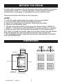
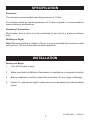
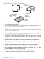
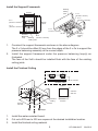
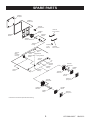
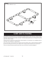
Watertile Rainshower
Installation and User Guide
MODEL NUMBERS
8030A
Important! Please quote the above model number(s) when ordering spares
IMPORTANT
INSTALLER: THIS MANUAL IS THE PROPERTY OF THE
CUSTOMER AND MUST BE RETAINED WITH THE PRODUCT
FOR MAINTENANCE AND OPERATIONAL PURPOSES.
1
1071288-AN2-F
09/03/12
BEFORE YOU BEGIN
All information is based on the latest product information available at the time
of publication. Kohler Co. reserves the right to make changes in product
characteristics, packaging, or availability at any time without notice.
Please leave these instructions for the consumer.
NOTES:
1. Flush the water supply pipes thoroughly to remove any debris.
2. An in line water filter must be used with this product.
3. Inspect the supply pipes for damage. Replace as necessary.
4. Observe local plumbing codes.
5. The recommended working pressure for the shower head is 150KPa to
500KPa. If the pressure exceeds 500KPa a pressure reducer is required.
6. Maximum water and environmental temperature for the shower head is
60C. Note: If a heater is present, make sure to keep it away from the shower
head as otherwise the environmental temperature may exceed 60C.
7. All installations should comply with the relevant requirements of AS/NZS
3500 and AS/NZS 6400.
DIMENSIONS
67 mm
60 mm
1/2" NPT
217 mm 127 mm
Center of
Water Inlet
1071288-AN2-F
251 mm
79 mm
Min Clearance
09/03/12
2
SPECIFICATION
Pressures
The minimum recommended operating pressure is 1.5 bar.
For multiple outlets an operating pressure of 3.0 bar or greater is recommended to
ensure optimum performance.
Plumbing Connections
Mixed water from a valve must be connected to the inlet of a pressure balance
loop.
Building in Depth
Note! Minimum building in depth is 79 mm. It is recommended that a minimum stud
wall cavity of 100 mm is provided to ease installation.
INSTALLATION
Before you Begin
1.
Turn off the water supply.
2.
Make sure that the Watertile Rainshower is installed by a competent installer.
3.
Before installation carefully inspect the new fixture for any signs of damage.
4.
Kohler Co. reserves the right to make revisions in the design of products without
notice.
3
1071288-AN2-F
09/03/12
Install the Supply Pipework - Single Supply
Pressure
Balancing Loop
127 mm
127 mm
Soldering Template
G1/2" Nipple
G1/2" Male Thread
Adapter with Flow
Control
Pressure
Balancing Loop
Soldering
Template
1.
2.
Install the water supply pipes.
Use the soldering template to construct a pressure balancing loop, this will
ensure correct alignment with the product.
Note! The loop pack is made from stronger pipe to give the pipework rigidity.
It is not standard copper pipe.
3.
4.
5.
Assemble the pressure balancing loop with a tee positioned over each of the
four raised locations on the soldering template.
If necessary, make each G½” tee fit snug to the soldering template by slightly
bending one tab on the template outward. Bend the same tab at each tee
position.
Repeat with the same relative tab on the remaining three nipple locations.
Note! The face of the G½” nipple must fit flush to the surface of the template.
6.
7.
8.
Solder the assembly whilst it is still attached to the soldering template.
Remove the pressure balancing loop from the soldering template.
After allowing the pressure balancing loop to cool, assemble the G 1/2” male
thread adapter with flow control to the loop.
9. Connect the pressure balancing loop to the water supply.
10. Temporarily install a nipple to each tee. Do not use any sealant.
1071288-AN2-F
09/03/12
4
Install the Support Framework
Existing
Ceiling
Joist
229 mm
2x2
(50 mm x 50 mm)
2x4
(50 mm x 100 mm)
2x4
(50 mm x 100 mm)
368 mm
Typical
2x2
(50 mm x 50 mm)
2x4
50 mm x 100 mm)
1.
2.
Existing
Ceiling
Joist
30 mm
Pressure
2 x4
Balancing
(50 mm x 100 mm)
Existing
Loop
Ceiling Joist
Construct the support framework as shown in the above diagram.
The 2 x 2 should be offset 30 mm from the edges of the 2 x 4’s to support the
pressure balancing assembly at the correct depth.
Install the support framework under the pressure balancing loop(s) as
illustrated.
The face of the 2x4’s should be installed flush with the face of the existing
ceiling joists.
Install the Finished Ceiling
Tee
57 mm Min
Finished Ceiling
Cutout
229 mm 235 mm
229 mm 235 mm
Tee
Finished
Ceiling
Cutout
229 mm 235 mm
Nipple
1.
2.
3.
Install the water-resistant board.
Cut out a 229 mm to 235 mm square at the desired installation location.
Install the finished ceiling material.
5
1071288-AN2-F
09/03/12
Install the Pipe Nipples
1.
2.
3.
4.
5.
6.
7.
8.
Remove the pipe nipples.
Note! The minimum distance between the face of the tees/elbows and the
surface of the finished ceiling should be 57 mm. The measurement for typical
installations is 70 mm.
Measure the distance from the face of the tees/elbows to the surface of the
finished ceiling. Make any adjustments as needed.
Install the nipples into the tee/elbows hand tight.
Measure the distance form the end of the nipples to the surface of the finished
ceiling. Make sure that the distance is at least 38 mm and no more than
44 mm.
If necessary, cut the G½” pipe nipples to length. Debur the ends.
Remove the nipples.
Apply thread sealant to the ends of the nipples and re-install the nipples to the
tees/elbows.
Run water through the system to flush out any dirt or debris.
Install the Waterway
Leak Shield
Concealing
Plate
Adapter
Socket Wrench
With Bit
Extension
Waterway
Screw
1.
2.
Insert the concealing plate into the opening. The double ribs of the leak shields
should be facing up.
If any of the leak shields make contact with an elbow, make sure
that you enlarge the hole in the back of the leak shield to
32 mm.
1071288-AN2-F
09/03/12
6
3.
4.
5.
6.
7.
Install the adapter onto one of the nipples using the 11 mm bit (supplied), 11
mm or 7/16” socket, the extension and the socket wrench.
Note! Use masking tape to hold the bit in place, as the bit could fall off and
cause damage.
Important! The concealing plate should sit loosely at this point. If it is tight
against the ceiling, use a longer pipe nipple.
Align the groove in the waterway with the double ribs on the leak shield.
Press the waterway into place over the adapter. Secure the waterway to the
adapter with the screw.
Make sure that the concealing plate does not turn or move.
Important! If the concealing plate is still loose after this step, then use a shorter
pipe nipple.
Repeat the procedure for the remaining waterways.
Install the Trim
Groove
Waterway
Ribs
Sprayhead
Hex Screws
Nozzle Membrane
Install the Sprayhead
1. With the ribs of the sprayhead facing upwards, attach the sprayhead to the
waterway.
2. Using a 3/16” hexagonal wrench, install the hexagonal screws to secure the
sprayhead in position. Do not overtighten.
3. Check the sprayhead for upward and downward movement and make sure
that it sits squarely within the concealing plate.
4. Place the nozzle membrane over the sprayhead.
5. Align the long edge of the membrane with the hinge ribs (horizontal).
Note! For optimum performance, make sure that the membrane is applied
evenly.
7
1071288-AN2-F
09/03/12
6.
Applying pressure evenly, press the membrane seal into the sprayhead
groove.
Install the Sprayface
Ribs
Finished Ceiling
Sprayface
Setscrews
1.
2.
3.
4.
5.
Tilt the sprayhead downward so that the ribs on the top of the sprayhead are
exposed.
Note! For product with brushed finishes, align the brush pattern of the sprayfaces
with the direction of the brushed pattern of the concealing plate.
Insert the grooves of the sprayface over the ribs of the sprayhead.
Press the sprayface down to cover the sprayhead, as illustrated.
Using a 5/64” hexagonal wrench, turn the setscrews anti-clockwise until they
are flush with the edge of the sprayface frame.
Important! The setscrews must be flush with the edge of the sprayface frame.
If the setscrews protrude outside the sprayface frame, product damage will
occur.
Repeat for the remaining sprayfaces.
1071288-AN2-F
09/03/12
8
SPARE PARTS
1054349
Template
1059024**
Escutcheon
1051498
Nipple G1/2”
1056179
3/16” Wrench
1036043
Shield
1055988
Gasket
1055233
Adapter
1051681
Screen Washer
1044060
O-Ring
1045773
Base
(Includes
Clamps)
1036038
Screw
1036040
Spacer
1071652
11 mm
Hex Bit
1032955
5/64” Wrench
1041362
Wire
1056104
Spring Washer
1045772
Elbow
1047041
Washer
1044058
O-Ring
1059514
Screw
1044059
O-Ring
1045768
Sprayhead
1036044
Clamp
1039745
Setscrew
1051487
Nozzle
1036041**
Spray Face
1045769
Sprayhead
1039745
Setscrew
1051682
Nozzle
1036044
Clamp
1041573**
Spray Face
**Finish/color code must be specified when ordering.
9
1071288-AN2-F
09/03/12
1080649
Kit - Pressure Balance Loop
1097221
Flow Control
1097222
Adapter
CARE AND CLEANING
Like anything of lasting quality, Kohler tapware and fittings require a certain amount of periodic care to
preserve their lustrous finish. Clean your new Kohler tapware and fittings with a mild soap, rinse thoroughly
with warm water and dry with a clean, soft cloth. The ideal cleaning technique is to always blot dry any
water from metal surfaces.
Allowing water to evaporate on metal will form water deposits. It is important to use a dabbing action to
dry metal, not an abrasive or rubbing action.
Never use cleaners containing abrasive cleansers, ammonia, bleach, acids, or chemicals that can damage
the finish. By taking the time to dry your tapware often, soap and water deposits can be prevented.
Failure to comply with these cleaning instructions may void Kohler’s warranty obligations.
1071288-AN2-F
09/03/12
10