1
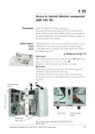
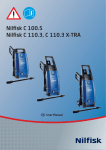
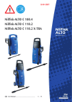
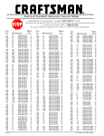
SERVICE MANUAL
PARTS LIST
SERVICIO
UPRIGHT VACUUM
CLEANER
MODELS:
U-40
KOBLENZ ELECTRICA S. A. DE C. V.
E-mail: [email protected]
JUANARY-2010
LP-U40-201001
1
INDEX
I.- FINAL TEST FOR PRODUCT SAFETY
3
II.- REPLACEMENT PROCEDURES
3
III.- TROUBLE SHOOTING CHART
5
IV.- UPRIGHT VACUUM CLEANER EXTERNAL PARTS
6
V.- PARTS LIST UPRIGHT VACUUM CLEANER
7
VI.- UPRIGHT VACUUM CLEANER INTERNAL PARTS
8
VII.- PARTS LIST UPRIGTH VACUUM CLEANER
9
VIII.- WIRING DIAGRAM
11
2
I.-FINAL TEST FOR PRODUCT SAFETY
After repairs the product should be tested on its electrical function and electric strength as follows.
1.-ELECTRIC TEST
1. Set hi-pot test meter at 1500 Volts
2. Place the handles tube to “ON” position
3. Touch one probe of tester to one blade of power cord plug and touch other probe to handle tube,
there should be no breakdown.
2.-OPERATING TEST
Run the machine with the height adjustment knob on high and check:
1. There should be no unusual noise or vibration.
2. The carbon brushes spark should be small and uniform.
3. The current should not exceed 9.0 Amps. and 7.0 Amps
II. REPLACEMENT PROCEDURES
1.-TO REMOVE BAG (8), FIG. 1
1.1.-Release spring, from handle, slide off coupling unit.
2.-TO REMOVE HANDLE TUBE (2, 9) FIG.1 y FIG.2
2.1.-Disengage line cord from hook (5) pulling cord outward from retainer bottom
2.2.-Remove screws and nuts (15 and 7) on handle socket (24) and pull tube out.
3.-TO REPLACE BELT (25), FIG.2
3.1.-To avoid damage on the cover place the upright upward wheels in a soft surface.
3.2.-Remove retaining bar (22) by pressing down on right side (Longest), remove brush rollers cover (23)
and assembly turbine cover (43).
3.3.-Stretch and twist belt over motor pulley to pull it out. (if not broken)
3.4.-Remove complete brush roller (21) with bearing supports (21B and 21E) pulling it out near the bearings.
3.5.- Place new belt on roller, replace roller on chassis making sure the mark "top" on bearings support
faces towards the brush roller cover and reassemble.
4.-TO REPLACE BRUSH ROLL ( 21 ) OR BEARING SUPPORTS FIG. 2.
4.1.-Follow steps 3.1 to 3.4.
4.2.-Remove bearing support (21-B), pulling away from them brush roller (old or new).
4.3.-Place bearing supports on new brush roll, place belt over roll and replace to on chassis following steps
3.5.
5.-TO REPLACE REAR WHEELS (5), FIG.2
5.1.-Remove cover (step 7)
5.2.-Pull security (6) from axle (41) and axle assembly take out.
5.3.-The wheels new replace on the axle.
5.4.-Replace Cover
6.-TO REPLACE FRONT WHEELS (14-I), FIG. 3, 4
6.1.-Remove cover (step 7)
6.2.-Remove screws (7) from axle supports (13) and axle assembly take out.
6.3.-Remove axle with wheels
6.4.-The wheels new replace on the axle.
6.5.-Axle assembly replace on chassis.
6.6.-Replace Cover
3
7.-TO REMOVE THE COVER (2), FIG. 1 AND FIG.2
7.1.-Remove the bag (8) (Fig. 1)
7.2.-Depress handle release pedal (39) and put on horizontal position the handle tube
7.3.-Remove the screw (14) and adjustment knob (1) (Fig.2)
7.4.-To avoid damage on the cover place the upright upward wheels in a soft surface, remove the insurance
8.-TO REPLACE MOTOR (51), FIG 2.
8.1.-Remove belts follow steps 3.1 to 3.3.
8.2.-Remove cover (step 7).
8.3.-Remove four screws (4) holding the motor and disconnect it.
8.4.-Replace the motor (51)
.
9.-TO REPLACE HEIGHT ADJUSTMENT CAM (I5), FIG.2
9.1.-Depress handle release pedal (39) and put on horizontal position the handle tube..
9.2.-Remove the screw (14) and the adjustment knob (1)
9.3.-Remove the spring and screw (44), to remove the retain cam plate.
10.-TO REPLACE HANDLE RELEASE PEDAL (39) FIG. 2
10.1.-Remove cover (step 7)
10.2.-Remove spring (40) from chassis
10.3.-Pull pedal towards spring side and remove
11.-TO REPLACE YOKE ASSEMBLY (24), FIG.2
11.1.-Remove cover (step 7)
11.2.-Remove handle release pedal (step 10)
11.3.-Remove the bolt yoke (31), along with the security locks (20)
12.-TO REPLACE THE CABLE ASSEMBLY (25), FIG. 2
12.1.-Remove cover (step 7)
12.2.-Remove Heyco strain relief (26) from chassis with Heyco
12.3.-Reassemble with the Hey co pliers making sure to locate the strain relief as it was before.
13.-TO REPLACE THE ON - OFF SWITCH (48), FIG. 2
13.1.-Remove cover (step 7)
13.2.-Disconnect the electrical terminal from the switch.
13.3.-Press the side tabs on the switch and pull it out.
13.4.-Press the new switch on the opening until the tabs snaps and reconnects the terminal.
14.-TO REPLACE THE SWITCH ACTUATOR (50), FIG.2
14.1.-Remove cover (step 7)
14.2.-Of the actuator assembly r emove the yoke (24).
14.3.-Replace the new actuator and assembly.
15.-MOTOR SERVICING,
The only possible motor repairs are: Replace carbon brushes, replace armature, replace field.
Never try to repair the field or armature, if defective, replace with a new one.
WHEN ORDERING, DO NOT FORGET TO SPECIFY:
PART NUMBER
DESCRIPTION
MODEL NUMBER
4
NOTE: Drawing numbers are for identification purposes only.
III.-TROUBLE SHOOTING CHART.
PROBLEM
A) Motor does not
work
B) Motor works but
cleaner does not
aspire
C) Motor works erratically
D) Brush roll vibrates.
E) Head light does
not run on
POSSIBLE CAUSE
1.- Not firmly plugged in.
2.- Bad ON-OFF switch.
3.- Line cord open
4.- Motor open
5.- Fan blockage by material
1.- Belt broken.
2.- Blockage air system.
3.- Fan broken.
4.- Worn brush roller.
5.- Motor slow.
6.- Bag full.
1.- Worn carbon brushes.
2.- Detective armature.
3.- Bad electrical connection.
4.- Detective On-Off switch.
1.- Ball bearing worn out..
2.- Ball bearing holder damaged
1.- Bad connections.
2.- Light bulb burned out.
5
SOLUTION
1.- Check attachment plug.
2.- Replace switch.
3.- Replace cord.
4.- Check motor and wiring.
5.- Remove obstruction
1.- Replace belt.
2.- Remove obstruction.
3.- Replace fan.
4.- Replace brush roller.
5.- Check carbon brushes.
6.- Empty bag (or change paper bag).
1.- Replace brushes.
2.- Check spark, replace
3.- Check wiring.
4.- Replace switch.
1.- Replace
2.- Replace ball bearing holder.
1.- Check wiring.
2.- Replace bulb.
IV.-UPRIGHT VACUUM CLEANER EXTERNAL PARTS
FIG. 1
6
VII.-PARTS LIST UPRIGHT VACUUM CLEANER
ITEM
1
2
3
4
5
6
7
8
9
10
11
12
13
14
15
15-A
15-B
16
17
18
19
20
21
21-A
21-B
21-C
21-D
21-E
22
23
24
25
26
27
28
29
30
30-A
30-B
31
32
33
34
35
36
37
38
39
40
No PART
QTY
DESCRIPTION
13-3147-9
1 KNOB CAM
13-2949-01-7
1 PLASTIC COVER UPRIGHT U-40
12-0936-0
1 BAFFLE
01-15006
4 SCREW B 10-16X3/4
13-3144-6
2 REAR WHEEL
04-0671-0
2 BLIND SECURITY TYPE HAT
01-1499-1
6 SCREW HEX No 10-16X5/8
01-0664-1
2 SCREW 10X5/8
04-0589-4
3 FLAT WASHER 5/16x1/2
24-0308-7
1 FRONT AXLE SPRING
13-3143-8
2 FRONT WHEEL
05-4489-0
3 RETEN PLATE SHAFT
25-1349-02-3
1 FRONT AXLE GALVANIZED
01-1651-7
1 SCREW TYPE BT No 6
46-3206-3
1 CAM ASSEMBLY
05-4722-4
1 CAM UPRIGHT
25-1345-5
1 BOLT FOR CAM
01-0093-3
2 SCREW No 6 X 5/8 TYPE BC/PHILLIPS
05-4721-6
1 RETEN CAM PLATE
13-2883-01-8
1 PLASTIC CHASSI U-40
12-0952-7
1 UPRIGHT FOR PLASTIC MOLDING
04-0469-9
1 SECURITY PADLOCK PO-25
46-2375-7
1 BRUSH ROLL ASSEMBLY
12-0522-8
1 PACKING FOR CARRIER BEARING
13-1801-3
1 CARRIER BEARING LEFT
37-0130-7
2 FELT FOR CARRIER BEARING
45-0299-3
1 ROLLER ASSEMBLY SOWS
13-1252-9
1 CARRIER BEARING 11/16
25-0997-4
1 RETEN ROD ROLLER COVER
46-3207-1
1 ROLLER ASSEMBLY COVER TILT
46-3433-3
1 SWITCH-ACTUATOR YOKE ASSEMBLY
28-1644-01-3
1 CABLE ASSEMBLY LINE U-40
12-0953-5
1 GROMET HEYCO 1232
02-0041-0
3 NUT HEX. No 10-24
04-0271-9
5 STAR WASHER No 10X204
05-4734-02-5
1 CHROME YOKE
46-3260-0
1 SUPPORT YOKE BUSHING ASSEMBLY
13-3148-7
2 YOKE BUSHING
05-4725-7
1 SUPPORT YOKE
25-1346-3
1 PIN FOR YOKE
12-0495-01-5
1 PACKING SEAL MOTOR BASE
01-0285-5
2 SCREW DE 8x3/4
13-2126-4
1 KNOB FOR EXCHANGE COUPLINGS
26-0001-3
1 FORK BULLETS LOCA
24-0014-1
1 KNOB SPRING FOR SWEEPER
04-0026-7
1 FLAT WASHER (02-0101)
13-2127-2
1 COUPLINGS RETEN BAG
05-4724-02-6
1 PEDAL HANDLE GALVANIZED
24-0316-0
1 PEDAL SPRING HANDLE UPRIGHT
9
ITEM
No PART
QTY
DESCRIPTION
41
25-1322-4
1 REAR WHEEL AXLE
42
05-4993-1
1 ANGLE FOR SOIL
43
46-3208-9
2 TURBINE COVER WITH SEAL ASSEMBLY
43-A
13-3145-3
1 TURBINE COVER
43-B
12-0834-7
1 TURBINE SEAL COVER GASKET
44
01-0270-7
2 SCREW 6X3
45
01-1683-0
1 SCREW TYPE T 8-32
46
05-0997-6
1 MOTOR SPACER
47
10-0137-9
1 STAPLE INSULATED CONNECTOR
48
11-0159-1
1 ROCKER SWICTH
49
12-0814-01-7
1 BELT 210 X 13 7 / 16 83 A
50
13-3273-3
1 ACTUATOR SWITCH
51
46-3383-0
1 MOTOR UPRIGTH 5A
52
28-1664-3
1 CABLE ASSEMBLY GROUND
52-A
09-1319-4
2 CABLE GREEN EARTH
52-B
30-0197-1
3 CONNECTION TERMINAL A
10
VIII.-WIRING DIAGRAM
11
FACTORY AUTHORIZED SERVICE
Thorne Electric Company
610 Lanark Suite 205
San Antonio TX, 78218
Tel. (210) 590-1226
Fax (210)590-1258
1-800-548-5741
S
E
FACTORY
KOBLENZ ELECTRICA S.A. DE C. V.
Av. Ciencia N.28
Cuautitlán Izcalli
Estado de México C. P. 54730
Web site : http://www.koblenz.com.mx
KOBLENZ ELECTRICA S.A. DE C. V.
E-: [email protected]
12
JUANARY-2010
LP-U40-201001