1
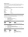
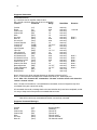
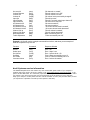
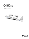
GRS44 8 Channel Eco-System™ Controller-Amplifier Installation Instructions v1.1 2 Important Safety Instructions: 1) Read these instructions. 2) Keep these instructions. 3) Read all warnings. 4) Follow all instructions. 5) Do not use this apparatus near water. 6) Clean only with dry cloth. 7) Do not block any ventilation openings. Install in accordance with the manufacturer’s instructions. 8) Do not install near any heat sources such as radiators, heat registers, stoves, or other apparatus (including amplifiers) that produce heat. 9) Do not defeat the safety purpose of the polarized or grounding-type plug. A polarized plug has two blades with one wider than the other. A grounding type plug has two blades and a third grounding prong. The wide blade or the third prongs are provided for your safety. If the provided plug does not fit into your outlet, consult an electrician for replacement of the obsolete outlet. 10) Protect the power cord from being walked on or pinched particularly at plugs, convenience receptacles, and the point where they exit from the apparatus. 11) Only use attachments/accessories specified by the manufacturer. 12) Use only with the cart, stand, tripod, bracket, or table specified by the manufacturer, or sold with the apparatus. When a cart is used, use caution when moving the cart/apparatus combination to avoid injury from tip-over. 13) Unplug this apparatus during lightning storms or when unused for long periods of time. 14) Refer all servicing to qualified service personnel. Servicing is required when the apparatus has been damaged in any way, such as power-supply cord or plug is damaged, liquid has been spilled or objects have fallen into the apparatus, the apparatus has been exposed to rain or moisture, does not operate normally, or has been dropped. 15).Under no circumstances should the output terminals of the amplifier be short-circuited. 16).Be sure that the loudspeakers connected can handle the output power of the amplifier at the loudspeakers rated impedance. The warranty on the amplifier does not cover damage to loudspeakers that have inadequate power handling capabilities. 17) Where an all-pole MAINS SWITCH is used as the disconnect device, the location on the apparatus and the function of the switch shall be described, and the switch shall remain readily operable. 18) A push button is used to turn the power off and on. 19) When the front panel push button switch is in the in position the apparatus is powered on. CAUTION: These servicing instructions are for use by qualified service personnel only. To reduce the risk of electric shock, do not perform any servicing other than that contained in the operating instructions unless you are qualified to do so. . Note: Where the mains plug or an appliance cover is used as the disconnect devise, the disconnect devise shall remain readily operable. WARNING: This product may contain chemicals, including lead, known to the State of California to cause birth defects or other reproductive harm. Wash hands after handling. 3 FCC Warning Note: This equipment has been tested and found to comply with the limits for a Class B digital device, pursuant to part 15 of the FCC Rules. These limits are designed to provide reasonable protection against harmful interference in a residential installation. This equipment generates, uses and can radiate radio frequency energy and, if not installed and used in accordance with the instructions, may cause harmful interference to radio communications. However, there is no guarantee that interference will not occur in a particular installation. If this equipment does cause harmful interference to radio or television reception, which can be determined by turning the equipment off and on, the user is encouraged to try to correct the interference by one or more of the following measures: Reorient or relocate the receiving antenna. Increase the separation between the equipment and receiver. Connect the equipment into an outlet on a circuit different from that to which the receiver is connected. Consult the dealer or an experienced radio/TV technician for help. Canada This Class B digital apparatus complies with Canadian ICES-003. Cet appareil numérique de la classe B est conforme à la norme NMB-003 du Canada. Caution: To reduce the risk of electrical shock, do not remove the cover (or back). No user serviceable parts inside. Refer to qualified service personnel. Warning: To reduce the risk of fire or electric shock, do not expose this appliance to rain or moisture. The lightning flash with arrowhead, within an equilateral triangle, is intended to alert the user to the presence of uninsulated “dangerous voltage” within the products that may be of sufficient magnitude to constitute a risk of electrical shock to persons. The exclamation point within an equilateral triangle is intended to alert the user to the presence of important operation maintenance (servicing) instructions in the literature accompanying the appliance. 4 Introduction: Thank you for your purchase of a Knoll GRS44 8 channel controller amplifier and congratulations on your choice. The GRS44 features four deluxe digital volume controlled stereo amplifiers with individual four source selection. This is Knoll's fourth generation of multi-channel, highquality power amplifiers. The GRS44 is designed to meet the amplifier needs of custom installed multi-zone systems where high quality sound is a specific requirement. Each of the four zones or rooms can select any of the four inputs, with individual volume control, bass and treble. Only the power button is located on the front panel. The GRS44 is controlled by RS232 commands. Four input source selection. Each of the four stereo amplifiers is provided with four input source selection. Selection, volume level, bass and treble is made using RS232 commands. Rooms can have different source selections, volumes, etc. Four internal 80 position stereo volume controls. GRS44 consists of a total of 8 power amplifiers in one 3-1/2" high enclosure (two rack spaces). Each power amplifier channel can deliver 30 watts RMS with peaks of 60 watts. Because of its unique design the GRS44 delivers exceptional value. GRS44 amplifier channel is individually and fully protected against low impedance, overheating, overloading, over voltage and under voltage. The protection circuitry automatically restores the amplifier channel as soon as its parameter returns to the safe operating area. and treble adjustment. Each channel features adjustments so installers can preset the room for speaker differences and listener preferences. 1 has line level outputs so more powerful power amplifiers can be connected to this output. The line level output is controlled as to volume, bass, treble and source selection. 5 Unpacking: The carton and packing materials used in shipping your new amplifier were specially designed to protect it from the shock and vibration of shipping. We suggest that you save the carton and packing materials to use if you move, or if the unit ever needs to be shipped back to us for any reason. Should you discover that your amplifier has been damaged during shipping, please contact your dealer or Knoll immediately and request the name of the carrier so a written claim can be made. The right to a claim against a public carrier can be forfeited if the carrier is not notified immediately in writing and if the shipping carton and packing materials are not available for inspection by the carrier. Save all packing materials until the claim is settled. GRS44 placement During normal home operation the amplifier will become warm. However, there are instances during high-level playback into low impedance speakers when the amplifier will become much warmer than normal. To ensure the amplifier’s trouble-free operation, it is necessary to provide adequate ventilation. Your amplifier should be kept away from external sources of heat such as radiators and hot-air ducts. The amplifier should never be placed with other heat-producing components in a cabinet or enclosure lacking free airflow. Do not stack other components on top of your amplifier. Connecting your amplifier When making connections between any source components and the amplifier, or when making connections to any speaker, be certain that both the input devices and the amplifier are turned off. Unplug all equipment before making any connections so that there will be no unwanted signal transients that can damage equipment or speakers. Input connections Connecting the GRS44 to your source equipment is straightforward. Using the highquality RCA audio interconnect cables, match the output channel designations on the rear of your source equipment to the input jacks on the rear panel of your amplifier that have the same channel name. When making connections with RCA type plugs on interconnect cables, make certain to gently, but firmly, insert the plug into the jack. Loose connections can cause intermittent sound and may damage your speakers. Some quality RCA plugs may be very tight, and it is important to secure a proper connection between the interconnection cable and the input jack. We suggest starting with the input gains on the rear of the GRS44 set to mid position. After it is installed and being tested these gains are use to set the different source input levels so they are roughly the same. Some sources such as DVD players have a very high output and may cause the GRS44 to send clipped signals to the speakers even at low volume levels, so we suggest lowering the input gains of that input in this case to stop the clipping 6 Speaker connections The GRS44 has four stereo 30 watts per channel amplified outputs. Channel 1 also has line level outputs to connect to larger powered amplifiers. To ensure that the high quality signals produced by your amplifier are carried to your speakers without loss of clarity or resolution, Knoll advises that you use high-quality speaker wire. Many brands of wire are available — the choice may be influenced by the distance between your speakers and the amplifier, the type of speakers you use, personal preferences, along with other factors. Regardless of the brand or type of speaker wire chosen, we suggest that you use a wire constructed of fine, multi-strand copper with a gauge of 16 or less (the lower the number, the thicker the cable). Wire with a gauge of 16 may be used for short runs of less than 12 feet. We do not recommend that you use any wires with an AWG equivalent of 18 or higher due to the power loss and degradation in performance. To connect the amplifiers to your speakers, a removable plug with screws is provided for each stereo channel output. Strip approximately 1/4 inch of insulation from the end of each wire and carefully twist the strands of each conductor together. Be sure not to cut the individual strands or twist them off. All strands must be used for optimal performance. Insert the wire into the plug and screw the screws very tight. Inspect that no wire “hairs” that can short circuit are not in the plug. Correct polarity connections are important to maintain proper speaker phasing. When speaker phasing is correct, all speakers move in and out at the same time preserving the imaging of the program material. Out-of-phase connections mean that some turn off, check your speakers to verify that they are operating properly. If all other potential sources of trouble check out properly, contact Knoll for further assistance. Run the cables to speaker locations. Do not coil any excess cable, as this may become an inductor that creates frequency response variations in your system. Lastly, connect the wires to the speakers, again being aware of proper polarity. Remember to connect the negative, or black wire, to the matching terminal on the speaker. The positive, or red wire should be connected to the matching terminal on the speaker. Note: While most speaker manufacturers follow industry convention of using red terminals for positive connections and black terminals for negative, some manufacturers may vary from this configuration. To ensure proper phase connections, and optimal performance, consult the identification plate on our speaker terminals, or the speaker’s manual to verify polarity. Contact the speaker’s manufacturer if you do not know the polarity of your speakers. 7 RS232 Connection The RS232 connection is used to control the GRS44 by an external controller or computer and can work with our without keypads. The GRS44 connects to the RS232 controller with a 9-pin db9 connector. The programming reference follows. 1.0 Terminal Settings To control the GRS44 amplifier via other control systems, connect a RS-232 cable to the serial control connector on the rear of the GRS44 and set your computer’s or control unit port settings to match the following configuration: SETTING VALUE Bits per second Data bits Parity Stop bits Flow control Emulation 19,200 8 None 1 None Auto detect 1.1 Command Summary All commands are enclosed in parentheses. The request can be in some cases a read request (followed by a “?”), or a write request (followed by 0-2 ASCII digits). A read command will return the current setting, and write command will change the setting. Read request format: (nAA?) where: ( starts the command n denotes amplifier channel (if required) AA denotes the command (may be 1 or 2 letters) ? denotes the read request ) ends the command Read Request Example 1.1: Function Command Response Volume returns the volume on channel 1 (0-87) (1vl?) Write request format (nAA$$) where: ( starts the command n denotes the amplifier channel (if required) AA denotes the command (may be 1, 2 or 3 letters !!) $$ denotes the value to be written if required (leading zero’s ARE necessary) ) ends the command Write Request Examples 1.2: Function Command Turn Channel On Select Input Set Volume (1on) (1sl4) (1vl50) Response turns on amplifier channel 1 on turn amplifier channel 1 to input 4 turn amplifier channel 1 to volume 50 (of 87) 8 Supported Commands Command Summary # = numerical zone or amplifier channel value $$ = second numerical value (may be one or two digits) Function Command Range Read/Write Version Reset Channel On Channel Off Mute Un-mute Mute All Un-mute All Volume Request Volume Set Volume All Input Request Input Set Input Select All All Channels On All Channels Off All Channels Vol up All Channels Vol dn Channel Vol up Channel Vol down Bass adjustment Treble adjustment Display treble Display bass read only write only write only write only write only write only write only write only read only write only write only read only write only write only write only write only write only write only write only write only write only write only read only read only (vr?) (rx) (#on) (#of) (#mu) (#um) (amu) (aum) (#vl?) (#vl$$) (avl$$) (#sl?) (#sl$) (asl$) (aon) (aof) (avlu) (avld) (#vlu) (#vld) (#b$) (#t$) (#b?) (#t?) none none 1-4 1-4 1-4 1-4 none none 1-4 1-4 / 0-87 0-87 1-4 1-4 / 1-4 1-4 none none none none 1-4 1-4 1-4 / 0-F 1-4 / 0-F 1-4 1-4 Remarks 1 second Note 3 Note 3 Note 3 Note 1 Note 1 Note 1 Note 1 Note 2 Note 2 Note1: Volume up or down requests increase or decrease volume level by 5 Note 2: Treble and bass commands use hexadecimal values 0-F, default (flat) is 8. Note3: After “ALL Channels Off” command an “Un-mute” must be sent to each channel to restore a channel volume. Also, it is best to leave about a ½ second between commands, as some integrators may miss commands if they are entered too quickly. All commands also send a message back to the terminal after they have been completed, so that it is easy to keep track of the previous commands that were sent. Note: Some commands are read or write only and some are both – for example: Mute All is a write only command and Version is a read only command. Supported Command Messages Function Command Message Version Reset Channel On Channel Off Mute Un-mute Mute All Version Number “Resetting...” “Zone # on” “Zone # off“ “Zone # muted” “Zone # unmuted” "All channels muted" (vr?) (rx) (#on) (#of) (#mu) (#um) (amu) 9 Un-mute All Volume Request Volume Set Volume All Input Set Input Request Input Select All All Channels Off All Channels On All Channels Vol up All Channels Vol dn Channel Vol up Channel Vol down Bass adjustment Treble adjustment (aum) (#vl?) (#vl$$) (avl$$) (#sl$) (#sl?) (asl$) (aof) (aon) (avlu) (avld) (#vlu) (#vld) (#b$) (#t$) "All channels un-muted" "Zone # volume level = $$" "Zone # volume level set" "All volume levels successfully changed" "Zone # input set" "Zone # is currently using input channel $” "All zones set to source $" "All zones turned off" “All zones turned on” “All zones volume levels increased” “All zones volume levels decreased” “Zone # volume increased” “Zone # volume decreased” “Bass successfully set to $” “Treble successfully set to $” Example 1.3: We will use the example commands from before, and show you an example of what the responses may look like Function Command Response Window On/Off Select Input Set Volume Set Bass Set Treble Increase Volume (1on) (1sl3) (1vl50) (1baf) (2ta) (2vlu) Zone 1 on Zone 1 input 3 set Zone 1 volume level = 50 Zone 1 Bass successfully set to 15 Zone 2 Treble successfully set to 10 Zone 2 volume increased Knoll Systems service information The GRS44 amplifier does not contain any user serviceable parts inside. If you suspect a problem that may require servicing, contact us at www.knollsystems.com/contact.html, or by phone at 800 566-5579. It is extremely important that only an authorized service dealer make any repairs. This will ensure proper service and preserve the protection of your warranty. Keep your receipt in a safe place so that it will be available to verify the purchase date, should you experience a problem covered by Knoll System’s warranty. 10 Troubleshooting Your Knoll amplifier is designed from trouble-free operation. If you follow the instructions in this manual, you should enjoy many years of high-quality listening enjoyment. However, as with any sophisticated device, there may be occasional problems upon initial installation, or during the life of the amp. The items on the list below are a brief guide to the minor problems that you may be able to correct yourself. If these solutions do not help, or if the problem persists, contact us for assistance at 1800 566 5579 in Canada or the USA or 604 940 1689. We are in the Pacific time zone. Problem Solutions Amplifier won’t turn on Master power switch turned off (No power light LED). Turn on Master Power Switch. Amplifier turns on, but no audio from one or more channels Input plugs not connected to proper jack or are loose. Check input connections. No audio from one or more Channels Speakers are not connected properly. Check speaker connections at amp and speaker. Audio levels differ from sources Improper settings or output levels from source device. Check the settings on your preamp, processor or controller. Also verify gain settings on the source inputs on the GRS44 rear panel. Audio plays and then cuts off Amplifier may be shorted. Check speaker connections for short-circuit at amp and speaker. Care, maintenance, and cleaning When the GRS44 amp becomes dirty, wipe it with a clean, dry, soft cloth. If necessary, first wipe the surface with a slightly dampened soft cloth with mild soapy water, then with a fresh cloth dampened with clean water. Wipe dry immediately with a dry cloth. NEVER use benzene, thinner, alcohol, or any other volatile cleaning agent. Do not use abrasive cleaners, as they will damage the finish of the metal parts. Avoid spraying insecticide, waxes, polishing agents, or any aerosol product near the GRS44. 11 Limited Warranty Knoll Systems, Inc. (“Knoll”) warrants that each GRS44 (“the Product”) sold hereunder will conform to and function in accordance with the written specifications of Knoll. Said limited warranty shall apply only to the first person or entity that purchases the Product for personal or business use and not for the purpose of distribution or resale. Said warranty shall continue for a period of three years from the date of such purchase. Knoll does not warrant that the Product will meet the specific requirements of the first person or entity that purchases the Product for personal or business use. Knoll’s liability for the breach of the foregoing limited warranty is limited to the repair or replacement of the Product or refund of the purchase price of the Product, at Knoll’s sole option. Replacement Product may be refurbished in “like-new” condition, at Knoll’s sole discretion. To exercise the Purchaser’s rights under the foregoing warranty, the Product must be returned at the Purchaser’s sole cost and expense, to Knoll or to any authorized Knoll service center provided, and the Product must be accompanied by a written letter explaining the problem and which includes (i) proof of date of purchase; (ii) the dealer’s name; and (iii) the model and serial number of the Product. When sending your unit in for repair, please ship your unit in its original packing material or a Knoll approved ATA Shipping Case, or have a professional packaging company pack the unit. Please insure your shipment for its full value. A return authorization number, issued by the Knoll customer service department, must also be clearly displayed on the outside of the shipping carton containing the Product. Note: Remanufactured Products are exempt from the foregoing Limited Warranty. Please refer to the Remanufactured Product Warranty for applicable warranty information. WARRANTY LIMITATION AND EXCLUSION Knoll shall have no further obligation under the foregoing limited warranty if the Product has been damaged due to abuse, misuse, neglect, accident, unusual physical or electrical stress, unauthorized modifications, tampering, alterations, or service other than by Knoll or its authorized agents, causes other than from ordinary use or failure to properly use the Product in the application for which said Product is intended. DISCLAIMER OF UNSTATED WARRANTIES THE WARRANTY PRINTED ABOVE IS THE ONLY WARRANTY APPLICABLE TO THIS PURCHASE. ALL OTHER WARRANTIES, EXPRESS OR IMPLIED, INCLUDING, BUT NOT LIMITED TO, THE IMPLIED WARRANTIES OF MERCHANTABILITY AND FITNESS FOR A PARTICULAR PURPOSE ARE DISCLAIMED. THERE ARE NO WARRANTIES THAT EXTEND BEYOND THE FACE HEREOF AND THE FOREGOING WARRANTY SHALL NOT BE EXTENDED, ALTERED OR VARIED EXCEPT BY WRITTEN INSTRUMENT SIGNED BY KNOLL. SOME STATES DO NOT ALLOW LIMITATIONS ON HOW LONG AN IMPLIED WARRANTY MAY LAST, SO SUCH LIMITATIONS MAY NOT APPLY TO YOU. LIMITATION OF LIABILITY IT IS UNDERSTOOD AND AGREED THAT KNOLL’S LIABILITY WHETHER IN CONTRACT, IN TORT, UNDER ANY WARRANTY, IN NEGLIGENCE OR OTHERWISE SHALL NOT EXCEED THE RETURN OF THE AMOUNT OF THE PURCHASE PRICE PAID BY PURCHASER AND UNDER NO CIRCUMSTANCES SHALL KNOLL BE LIABLE FOR SPECIAL, INDIRECT, INCIDENTAL OR CONSEQUENTIAL DAMAGES OR LOST PROFITS, LOST REVENUES OR LOST SAVINGS. THE PRICE STATED FOR THE PRODUCT IS A CONSIDERATION IN LIMITING KNOLL’S LIABILITY. NO ACTION, REGARDLESS OF FORM, ARISING OUT OF THE AGREEMENT TO PURCHASE THE PRODUCT MAY BE BROUGHT BY PURCHASER MORE THAN ONE YEAR AFTER THE CAUSE OF ACTION HAS ACCRUED. SOME STATES DO NOT ALLOW THE EXCLUSION OR LIMITATION OF INCIDENTAL OR CONSEQUENTIAL DAMAGES SO THE ABOVE LIMITATION OR EXCLUSION MAY NOT APPLY TO YOU. THIS LIMITED WARRANTY GIVES YOU SPECIFIC LEGAL RIGHTS, AND YOU MAY ALSO HAVE OTHER RIGHT WHICH VARIES FROM STATE-TOSTATE. Copyright 2013 Knoll Systems. All Rights Reserved. Knoll Systems 14-7163 Vantage Way, Delta BC V4G 1N1 Canada 145 Tyee Drive, Point Roberts, WA 98281 USA Made in Canada