1
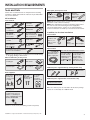
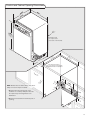
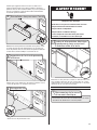
INSTALLATION INSTRUCTIONS
UNDERCOUNTER DISHWASHER
INSTRUCTIONS D'INSTALLATION
LAVE-VAISSELLE SOUS PLAN DE TRAVAIL
Table of Contents . . . . . . . . . . . . . . . . . . . . . . . . . . . . . . . . . . . 2
Table des matières . . . . . . . . . . . . . . . . . . . . . . . . . . . . . . . . . . 27
W10275503B
Table of Contents
Dishwasher Safety . . . . . . . . . . . . . . . . . . . . . . . . . . . . . . . . . 2
Installation Requirements . . . . . . . . . . . . . . . . . . . . . . . . . . . 3
Installation Instructions
(cont.)
Install the Door Handle . . . . . . . . . . . . . . . . . . . . . . . . . . . 14
Tools and Parts. . . . . . . . . . . . . . . . . . . . . . . . . . . . . . . . . . . 3
Custom Panel Dimensions . . . . . . . . . . . . . . . . . . . . . . . . 14
Location Requirements . . . . . . . . . . . . . . . . . . . . . . . . . . . . 4
Install Custom Panel - Option 1 . . . . . . . . . . . . . . . . . . . . 15
Drain Requirements. . . . . . . . . . . . . . . . . . . . . . . . . . . . . . . 6
Install Custom Panel - Option 2 . . . . . . . . . . . . . . . . . . . . 17
Water Supply Requirements . . . . . . . . . . . . . . . . . . . . . . . . 6
Choose Attachment Option. . . . . . . . . . . . . . . . . . . . . . . . 17
Electrical Requirements. . . . . . . . . . . . . . . . . . . . . . . . . . . . 6
Move Dishwasher Into Cabinet Opening. . . . . . . . . . . . . 18
Installation Instructions . . . . . . . . . . . . . . . . . . . . . . . . . . . . . 7
Connect to Water Supply . . . . . . . . . . . . . . . . . . . . . . . . . 20
Prepare Cabinet Opening—Existing Utilities. . . . . . . . . . . 7
Connect to Drain . . . . . . . . . . . . . . . . . . . . . . . . . . . . . . . . 21
Prepare Cabinet Opening—New Utilities. . . . . . . . . . . . . . 7
Make Direct Wire Electrical Connection. . . . . . . . . . . . . . 21
Prepare and Route Water Line . . . . . . . . . . . . . . . . . . . . . . 8
Secure Dishwasher in Cabinet Opening . . . . . . . . . . . . . 23
Install Drain Hose . . . . . . . . . . . . . . . . . . . . . . . . . . . . . . . 10
Bottom Sound Pad Installation. . . . . . . . . . . . . . . . . . . . . 24
Install Moisture Barrier . . . . . . . . . . . . . . . . . . . . . . . . . . . 11
Complete Installation. . . . . . . . . . . . . . . . . . . . . . . . . . . . . 24
Prepare Dishwasher . . . . . . . . . . . . . . . . . . . . . . . . . . . . . 11
Check Operation. . . . . . . . . . . . . . . . . . . . . . . . . . . . . . . . . 26
Make Power Supply Cord Connection . . . . . . . . . . . . . . . 12
If Dishwasher Does Not Operate . . . . . . . . . . . . . . . . . . . 26
Determine Cabinet Opening . . . . . . . . . . . . . . . . . . . . . . . 13
Additional Tips . . . . . . . . . . . . . . . . . . . . . . . . . . . . . . . . . . 26
DISHWASHER SAFETY
Your safety and the safety of others are very important.
We have provided many important safety messages in this manual and on your appliance. Always read and obey all safety
messages.
This is the safety alert symbol.
This symbol alerts you to potential hazards that can kill or hurt you and others.
All safety messages will follow the safety alert symbol and either the word “DANGER” or “WARNING.”
These words mean:
DANGER
WARNING
You can be killed or seriously injured if you don't immediately
follow instructions.
You can be killed or seriously injured if you don't follow
instructions.
All safety messages will tell you what the potential hazard is, tell you how to reduce the chance of injury, and tell you what can
happen if the instructions are not followed.
WARNING
Tip Over Hazard
Do not use dishwasher until completely installed.
Do not push down on open door.
Doing so can result in serious injury or cuts.
2
You Need to:
• Slowly open dishwasher door while someone grasps the
rear of the dishwasher. Remove shipping materials, drain
hose and lower rack. Close dishwasher door until latched.
• Observe all governing codes and ordinances.
• Install this dishwasher as specified in these instructions.
• Installation should be performed by a qualified service
technician. The dishwasher must be installed to meet all
electrical and plumbing national and local codes and
ordinances.
INSTALLATION REQUIREMENTS
Tools and Parts
Other parts you may also need:
Gather the recommended tools and parts before starting
installation. Read and follow the instructions provided with
any tools listed here.
All Installations
Tools needed:
Flat-blade
screwdriver
Phillips
screwdriver
Utility knife
"
"
nut drivers or
hex sockets
UL Listed or CSA
Approved twist-on
wire connectors*
Measuring tape
or ruler
Small level
10" adjustable wrench
that opens to
"
"
wrench
Wood block
Tools needed:
Small
tubing cutter Wire stripper
Parts needed:
*Must be the proper size to connect your household wiring
to 16-gauge wiring in dishwasher
Other useful items you may need:
Shallow pan
In addition, for first-time installations
Cordless drill
with ¹⁄₂", ³⁄₄"
and 1¹⁄₂" hole
saw bits
If installing custom front panels,
Torx®† T15 screwdriver
Bath towel
Masking or Moisture
barrier tape
duct tape
(Part Number
4396277).
NOTE: Moisture barrier tape is recommended when installing a
dishwasher under a wood countertop.
NOTE: Parts available for purchase in plumbing supply stores.
Check local codes. Check existing electrical supply. See
“Electrical Requirements” section. It is recommended that
electrical connections be made by a licensed electrical installer.
Pliers
Flashlight
(3.81–5.0 cm)
Screw-type
clamps (3 maximum)
Copp
O.D. suggested) or
flexible braided
water supply line
See “Electrical Requirements” section
For Direct Wire:
use UL Listed/
CSA Approved
strain relief
For Power Supply
Cord: use UL
Listed power
supply cord kit
marked for use
with dishwasher
hole
Additional parts supplied with top-venting models only:
" Torx® T15 screws
"
Parts supplied:
Drain hose
clamps (2)
(1 large and
1 small)
Drain hose
Phillips-head
screws (2)
2 – undercounter
mounting
brackets (top)
Additional parts supplied with certain models only:
Bottom sound pad
(located in lower rack)
Make
sure
all these parts are included in the literature package.
Silver
Green
Make sure all these parts are included in the literature package.
Parts needed:
If parts are not included, call 1-800-422-1230.
³⁄₈" Compr x ³⁄₄" Hose Fitting.
For part or kit, see local
retailer or call Whirlpool
Parts: 1-800-442-9991. Part
Number W10273460
4 #10 x ¹⁄₂" wood screws (if installing custom front panels)
†® TORX is a registered trademark of Acument Intellectual Properties, LLC.
3
Location Requirements
Grounded electrical supply required.
Do not run drain lines, water lines or electrical wiring where
they can interfere with or contact dishwasher motor or legs.
The location where the dishwasher will be installed must
provide clearance between motor and flooring. Motor
should not touch the floor.
Do not install dishwasher over carpeted flooring.
Shelter dishwasher and water lines leading to dishwasher
against freezing. Damage from freezing is not covered by
the warranty.
A side panel kit is available from your dealer for installing
your dishwasher at the end of your cabinetry.
A moisture barrier accessory (Part Number 4396277) is
available from your dealer for installing underneath the
countertops. Call 1-800-422-1230 to order.
4
Check location where dishwasher will be installed. The
location must provide:
• easy access to water, electricity and drain.
• convenient access for loading and unloading dishes.
Corner locations require a 2" (5.1 cm) minimum
clearance between the side of the dishwasher door
and the wall or cabinet.
• square opening for proper operation and appearance.
• cabinet front perpendicular to floor.
• level floor. (If floor at front of opening is not level with
floor at rear of opening, shims may be needed to level
dishwasher.)
Helpful Tip: Be sure to accurately measure dimensions
and ensure dishwasher is level if the floor in the
dishwasher opening is uneven (example: Flooring
extends only partway into opening).
NOTE: To avoid shifting during dishwasher operation,
shims must be securely attached to the floor.
If dishwasher will be left unused for a period of time or in a
location where it may be subject to freezing, have it
winterized by authorized service personnel.
Make sure pipes, wires and drain hose are within the
shaded area shown in the “Product and Cabinet
Opening Dimensions” section.
Product and Cabinet Opening Dimensions
)
.1
(64
cm
(60
.6
cm
)
m)
c
2.2
(6
*
m)
9c
(86
wi cm
th )
remwh mi.n
ov eels
ed
(1.
*Insulation may
be compressed.
(not used on all models)
"
"
21 m)
.3
(53
c
24cm)
(6124"
cm
)
(61
**
Check that all surfaces
have no protrusions that would
prohibit dishwasher installation.
(17
.2
"
34 m)
c
.4
(86min*
2c
.
(10
NOTE: Shaded areas of cabinet walls show where
utility connections may be installed.
3" m)
6c
*Measured from the lowest point on the
underside of countertop. May be reduced to
33⁷⁄₈" (86 cm) by removing wheels from
dishwasher.
cm
)
4" m)
(7.
(4.
(26
.7
4c
(6.
m)
4c
m)
cm
)
(15
.9
cm
)
**Minimum, measured from narrowest point of
opening.
Cle
Arear
a
2" m)
1c
(4
.
4
cm
)
(5.
5
Drain Requirements
Electrical Requirements
• A new drain hose is supplied with your dishwasher.
If drain hose is not long enough, use a new drain hose
with a maximum length of 12' (3.7 m) (Part Number
3385556) that meets all current AHAM/IAPMO test
standards, is resistant to heat and detergent, and fits the
1" (2.5 cm) drain connector of the dishwasher.
Be sure that the electrical connection and wire size are
adequate and in conformance with the National Electrical
Code, ANSI/NFPA 70 - latest edition and all local codes and
ordinances.
• Make sure to connect drain hose to waste tee or disposer
inlet above drain trap in house plumbing and 20"
(50.8 cm) minimum above the floor. It is recommended
that the drain hose either be looped up and securely
fastened to the underside of the counter, or be connected
to an air gap.
Use of air gap
Air gap
• Make sure to use an air gap if the drain hose is connected
to house plumbing lower than 20" (50.8 cm) above
subfloor or floor.
• Use ¹⁄₂" minimum I.D. drain line fittings.
• If required, the air gap, should be installed in accordance
with the air gap installation instructions. When you are
connecting the air gap a rubber hose (not provided) will
be needed to connect to the waste tee or disposer inlet.
Water Supply Requirements
• A hot water line with 20-120 psi (138-862 kPa) water
pressure can be verified by a licensed plumber.
• 120°F (49°C) water at dishwasher.
• ³⁄₈" O.D. copper tubing with compression fitting or
flexible braided water supply line (Part Number
4396897RP)
NOTE: ¹⁄₂" minimum plastic tubing is not recommended.
• A 90° elbow with ³⁄₄" Hose connection with rubber
washer
• Do not solder within 6" (15.2 cm) of the water inlet valve.
6
A copy of the above code standards can be obtained from:
National Fire Protection Association
One Batterymarch Park
Quincy, MA 02269
You must have:
• 120-volt, 60 Hz, AC-only, 15- or 20-amp, fused electrical
supply.
• copper wire only.
We recommend:
• a time-delay fuse or circuit breaker.
• a separate circuit.
If connecting dishwasher
with a power supply cord:
• Use UL Listed power supply cord kit (Part Number
4317824) marked for use with dishwasher.
• Power supply cord must plug into
a grounded 3 prong outlet, located in
the cabinet next to the dishwasher
opening. Outlet must meet all local
codes and ordinances.
If connecting dishwasher with direct wiring:
• Use flexible, armored
or nonmetallic
sheathed, copper wire
with grounding wire
that meets the wiring requirements for your home and
local codes and ordinances.
• Use a UL Listed/CSA Approved strain relief.
INSTALLATION INSTRUCTIONS
Prepare Cabinet Opening—Existing
Utilities
1
Check water and electrical
placement
Water line
Electrical Shock Hazard
Disconnect electrical power at the fuse box or circuit
breaker box before installing dishwasher.
Failure to do so can result in death or electrical shock.
(15 6
.2 ”
cm
)
Cable
1
Disconnect power
Disconnect electrical power at the fuse box or circuit
breaker box before installing dishwasher.
2
3
If the water line and the cable extend to the locations
shown, proceed to the “Install Drain Hose” section. If they
do not reach far enough, follow the instructions in the
“Prepare Cabinet Opening—New Utilities” section.
Prepare Cabinet Opening—New
Utilities
Do you already have utility
hookups?
Yes —Follow instructions in the “Prepare Cabinet
Prepare and route the electrical supply
What type of electrical
connection will you use?
Opening—Existing Utilities” section.
Power Supply Cord:
Follow Option A instructions
No —Follow instructions in the “Prepare Cabinet
Opening—New Utilities” section.
Existing utility hookups
Direct Wire:
Follow Option B instructions
No existing utility hookups
Water line
Option A, Power Supply Cord:
NOTE: A grounded 3 prong outlet is required inside a
cabinet next to the dishwasher cabinet opening.
1
Power Supply Cord—Drill hole
Cable
Optional loc
location
ation
Pref rred loc
Preferred
location
ation
(3.8 cm)
Drill a 1¹⁄₂" (3.8 cm) hole in cabinet side or rear.
See product and cabinet opening dimensions.
7
2
Power Supply Cord–Prepare hole
3
Direct Wire–Route cable
(15 6
.2 ”
cm
)
Metal
cabinet
Wood
cabinet
Wood cabinet: Sand the hole until smooth.
Metal cabinet: Cover hole with grommet included with
power supply cord kit.
Option B, Direct Wire:
Helpful Tip: Wiring the dishwasher will be easier if you
route the cable into the cabinet opening from the right-hand
side.
1
Direct Wire — Drill hole
Route cable from power supply through cabinet hole (cable
must extend to the right front side of cabinet opening).
Tape cable to the floor in area shown. This will prohibit
cable from moving when dishwasher is moved into
cabinet opening.
Prepare and Route Water Line
Helpful Tip: Routing the water line through the left side
of cabinet opening will make water connection easier.
1
Drill hole
Optional location
Preferred
Preferredlocations
locations
Preferred
Preferred lolocation
cation
Optional
Optionallocations
loc
ations
(1.9 cm)
¹⁄₂"
(1.3 cm)
Drill a ³⁄₄" (1.9 cm) hole in right-hand cabinet side or rear.
See product and cabinet opening dimensions.
2
Direct Wire–Prepare hole
Drill a ¹⁄₂" (1.3 cm) hole in the cabinet side or rear.
2
Measure water supply line
Hot water line
Wood
cabinet
Metal
cabinet
Wood cabinet: Sand the hole until smooth.
Metal cabinet: Cover hole with grommet (Part Number
302797 - not provided).
8
Measure overall length of copper tubing or flexible
braided water supply line. Attach to the hot water line
using a connection configuration that is in compliance
with local codes and ordinances. The water line to the
dishwasher should have a manual shutoff valve.
3
Route water supply line
5
Slide nut and ferrule
onto tubing
Nut
Ferrule
Slowly route water supply line through hole in cabinet.
(If using copper tubing, it will bend and kink easily, so be
gentle.) It should be far enough into the cabinet opening
to connect it to the dishwasher inlet on the front left
side of the dishwasher.
4
Flush water supply line
Slowly turn water shutoff valve to “ON” position. Flush
water into a shallow pan until clear to get rid of particles
that could clog the inlet valve. Turn shutoff valve to
“OFF” position.
Copper tubing only: Slide nut, then ferrule, about 1"
(2.5 cm) onto copper tubing.
NOTE: To avoid vibration during operation, route the
water supply line so that it does not touch the
dishwasher base, frame or motor.
6
Add 90° elbow fitting to the
water supply line
Connect the ³⁄₈" compression fitting to the water supply
line prior to installing the unit into the cabinet opening.
Attach such that the ³⁄₄" connection is facing upward as
shown below.
Copper tubing only: Put the tubing into the 90° elbow
fitting as far as it will go (the copper tubing bends and
kinks easily). Slide the nut and ferrule forward and start
the nut onto the elbow threads.
Flexible braided connection: Secure nut to elbow using
⁵⁄₈" open ended wrench or adjustable wrench.
NOTE: Do not use Teflon®† tape with compression
fittings.
†® Teflon is a registered trademark of E.I. Du Pont de Nemours and
Company.
9
Option A, Waste disposer – no air gap
Install Drain Hose
IMPORTANT: Always use a new drain hose. Check local
codes to determine whether an air gap is required.
Waste disposer – no air gap
Large silver
drain hose clamp
Disposer inlet
1
Drill hole
Drain hose
Drain trap
1¹⁄₂"
(3.8 cm)
If needed, drill a 1¹⁄₂" (3.8 cm) diameter hole in cabinet wall
or side of the opening closest to the sink.
2
1
1. Using a hammer and screwdriver,
knock plug into disposer.
2
2. Use needle-nose pliers to remove
plug.
3
3. Attach drain hose to disposer inlet
with large silver drain hose clamp
(provided). Use pliers to squeeze
clamp open and move into position.
Route drain hose
Drain hose
Option B, No waste disposer – no air gap
No waste disposer – no air gap
Route drain hose as shown through hole in cabinet to the
front center of opening where drain connection will be
made. Tape drain hose to the floor in area shown. This will
prohibit it from moving when dishwasher is moved into
cabinet opening.
3
Screw-type
Large silver
drainclamp
hose clamp
Waste tee
Drain hose
Connect drain hose
Drain trap
Connect drain hose to waste tee or waste disposer
using one of the following options:
• Option A, Waste disposer – no air gap
• Option B, No waste disposer – no air gap
• Option C, Waste disposer – with air gap
• Option D, No waste disposer – with air gap
IMPORTANT: The drain hose connection of the disposer or
a waste tee must be made before the drain trap and at
least 20" (50.8 cm) above the floor where the dishwasher
will be installed.
Helpful Tip: To reduce vibration of the hose, keep the hose
away from the floor.
10
1
2
Black end
1. Connect black end of of drain hose to
waste tee and cut if needed.
(Do not cut ribbed section.)
2. Attach black end of drain hose to waste
tee with a large silver drain hose clamp
(provided). Use pliers to squeeze clamp
open and move into position. If the drain
hose was cut, use a 1¹⁄₂" to 2" (3.8 to
5 cm) screw-type clamp (not provided).
Option C, Waste disposer – with air gap
Install Moisture Barrier
(under a wood countertop)
Waste disposer – with air gap
Air gap
Screw-type clamps
Disposer inlet
Large silver drain
hose clamp
clamp
hose
(provided)
Install moisture barrier
(under a wood countertop)
Rubber hose
connector
Drain hose
Moisture
barrier
Drain trap
1. Using a hammer and screwdriver,
knock plug into disposer.
1
2. Use needle-nose pliers to remove
plug.
2
3
3. Connect black end of drain hose to air
gap and cut if needed. (Do not cut
ribbed section.)
Black end
4
4. Attach drain hose to air gap with large
silver drain hose clamp (provided).
Use pliers to squeeze clamp open and
move into position. If the drain hose
was cut, use a 1¹⁄₂" to 2" (3.8 to
5 cm) screw-type clamp (not
provided).
1. Make sure the area under the cabinet is clean and dry
for installation of the moisture barrier.
2. Remove the backing of the moisture barrier and apply
to underside of the countertop along the front edge of
the counter.
Prepare Dishwasher
5. Use a rubber hose (not provided) with
screw-type clamps (not provided) to
connect from air gap to disposer inlet.
5
Tip Over Hazard
Option D, No waste disposer – with air gap
No waste disposer – with air gap
Waste tee
Rubber hose
connector
Drain hose
Drain trap
1
2
3
Do not push down on open door.
Doing so can result in serious injury or cuts.
Air gap
Large silver drain
hose clamp
(provided)
Screw-type clamps
Black end
Do not use dishwasher until completely installed.
1. Connect black end of drain hose to air
gap and cut if needed. (Do not cut
ribbed section.)
Excessive Weight Hazard
Use two or more people to move and install
dishwasher.
Failure to do so can result in back or other injury.
1
Put dishwasher on its back
2. Attach drain hose to air gap with large
silver drain hose clamp (provided).
Use pliers to squeeze clamp open and
move into position. If the drain hose
was cut, use a 1¹⁄₂" to 2" (3.8 to 5 cm)
screw-type clamp (not provided).
3. Use a rubber hose (not provided) with
screw-type clamps (not provided) to
connect from waste tee to air gap.
11
Helpful Tip: Place cardboard under dishwasher until installed
in cabinet opening to avoid damaging floor covering. Do not
use door panel as a worktable without first covering with a
towel to avoid scratching the door panel.
What type of electrical
connection will you use?
Using two or more people, grasp sides of dishwasher door
frame and place dishwasher on its back.
2
Power Supply Cord:
Follow Option A instructions
Remove panels
Direct Wire:
Follow Option B instructions
NOTE: If using Option B, proceed to “Determine Cabinet
Opening,” to continue with the installation of your
dishwasher.
Make Power Supply Cord Connection
Option A, Power Supply Cord:
Using a ¹⁄₄" hex head socket, nut driver or Phillips
screwdriver, remove two screws attaching access panel
and lower panel to dishwasher. Do not remove tech
sheet from access panel.
3
Power Cord—Route cord
into terminal box
Remove terminal box cover
Using a ¹⁄₄" hex head socket, nut driver or Phillips
screwdriver, remove terminal box cover. Retain for
later use.
4
Install a UL Listed/CSA Approved strain relief. Make sure
screwheads are facing to the left when tightening conduit
nut. Strain relief is provided with the power supply cord kit.
12
1
Route cord so that it does not touch dishwasher motor to
lower part of dishwasher tub. Pull cord through strain
relief in terminal bow. Take notice when installing or
removing the dishwasher in order to reduce the chance of
damaging the power supply cord.
Select UL Listed/CSA Approved twist-on wire connectors
(included with power supply cord kit) rated to connect your
power supply cord to 16-gauge dishwasher wiring.
WARNING
4
Power Cord−Secure cord
on strain relief
Electrical Shock Hazard
Electrically ground dishwasher.
Connect ground wire to green ground connector
in terminal box.
Do not use an extension cord.
Failure to follow these instructions can result in
death, fire, or electrical shock.
2
Power Supply Cord—
Connect ground wire
Tighten strain relief screws to secure cord.
5
Ground
wire
Power Cord—Reinstall
terminal box cover
Ground
wire
Washer
Ground
connector
Remove the green grounding screw and place
through the ring terminal of the green ground wire.
Reattach and tighten the green screw.
3
Power Cord—Connect
remaining wires
Place wires inside terminal box. Insert tabs
on left side of cover. Make sure wires are tucked inside
box. Close cover ensuring wires are not pinched. Use ¹⁄₄"
nut driver and previously removed screw to secure
cover.
NOTE: Do not plug into outlet until instructed to do so.
Determine Cabinet Opening
NOTE: Twist on wire connector. Gently tug on wires to be
sure both are secured.
Connect wires black to black and white to white, using UL
Listed/CSA Approved twist-on wire connectors (included
with power supply cord kit).
1
Measure cabinet opening
Wiring configuration
Power supply wire:
white
black
ground wire
Terminal box wire:
white
black
ground connector
If needed, see website for animated representation of this
step. Visit www.kitchenaid.com under FAQ tab.
13
Measure height of cabinet opening from underside of
countertop to floor where dishwasher will be installed
(you will need to measure the lowest point on the
underside of the countertop and the highest point on the
floor). Refer to “Dishwasher Height Adjustment Chart”
for wheel position and the number of turns needed.
Install the Door Handle
(on some models)
Install door handle
Dishwasher Height Adjustment Chart
Cabinet
opening height
34" (86.4 cm)
(87.0 cm)
Wheel
position
Number of turns
on front leg
Removed
All the way up
1
10
2
5
3
0
Mounting stud
Handle
Setscrew
(in bottom
of handle)
Allen wrench
NOTE: If the minimum cabinet opening height is less than
34"(86.4 cm), the rear wheels can be removed for
additional clearance. This will allow the dishwasher to fit
into a 33⁷⁄₈" (86 cm) high cabinet opening, but the
dishwasher will be more difficult to move. (Measurements
are approximate. Wheels and legs are preset at the
factory for 34¹⁄₂" [87.6 cm].)
Adjust wheels and legs
2
IMPORTANT: Do not scratch the front panel during this
procedure.
Remove the door handle and hardware bag containing the
setscrews and Allen wrench from the cardboard box.
Setscrews are already installed in the handle. Place handle
on mounting studs with the setscrews facing down. Push
the door handle tightly against the door. Insert the short
end of the Allen wrench into the setscrews. Tighten the
setscrews ¹⁄₄ turn past snug.
Retain Allen wrench with Installation Instructions.
Custom Panel Dimensions
IMPORTANT: You need to know which control panel is on
your dishwasher before you order your custom door
panel.
1
2
3
Custom panel dimensions—Dishwashers
with control panel on the top
wheel
Turn both leveler legs to the same height. Put wheels in
the required position determined from “Dishwasher
Height Adjustment Chart.”
3
(59.7 cm)
Built-up Floors—Add
shims as needed
³⁄₄" (19.1 mm)
(7
cm
)
(1
0. 4"
1
cm
)
(52"
cm
)
Built-up floors: If the kitchen floor is higher than the
cabinet opening's floor - for example, the kitchen floor tile
does not extend into the cabinet opening - add shims as
needed in the area shown to bring the dishwasher up to
34" (86.4 cm) below the countertop.
NOTE: Shims must be securely attached to floor to avoid
movement when the dishwasher is in use.
14
* This dimension is for 4" (10.2 cm) toe kick. If the
installation needs a higher toe kick, adjust the height
of the wood panel accordingly. Not recommended for
toe kicks greater than 6" (15.2 cm).
Follow directions under Option 1 of “Install custom
panel” section.
Custom panel dimensions - Dishwashers
with control panel on the front
1
Custom panel installation Dishwashers with control
panel on the top
(65.8 cm)
23¹⁄₂"
(59.7 cm)
*30³⁄₁₆" (76.7 cm)
(19.1 mm)
³⁄₄" (19.1 mm)
(3.2 mm)
* This dimension is for 4" (10.2 cm) toe kick. If the
installation needs a higher toe kick, adjust the height
of the wood panel accordingly. Not recommended for
toe kicks greater than 6" (15.2 cm).
Follow directions in Option 2 of “Install custom panel”
section.
Install Custom Panel – Option 1
(Models KUDS40FVPA, KUDS50FVPA, KUDE60FVPA,
and KUDE70FVPA)
* This dimension is for 4" (10.2 cm) toe kick. If the
installation needs a higher toe kick, adjust the height
of the wood panel accordingly. Not recommended for
toe kicks greater than 6" (15.2 cm).
With a TORX® screwdriver, remove three screws from both
sides, as shown; hold the outer panel up while removing
the screws. Save screws for reinstallation.
2
Custom panel dimensions—
Dishwashers with control panel
on the top
NOTE: The handle for the custom panel is not included.
IMPORTANT: If the handle is attached from the back of
the custom panel, the screw holes should be countersunk
for the screws heads to be flush with the panel. If the
handle is attached to the front of the custom panel, the
screw lengths cannot exceed the panel thickness. For
more information on KitchenAid custom handle
selection, refer to the KitchenAid Catalog, visit
www.kitchenaid.com, or call 1-800-422-1230.
NOTE: A customer-supplied full-front panel must weigh
no more than 16 lbs (7.3 kg) and must be made to
specific dimensions. It is recommended that a
cabinetmaker cut the custom panel because of the
precise dimensions needed.
NOTE: All mounting hardware supplied is for a ³⁄₄"
(19.1 mm) thick wood panel. If a thinner wood panel, or
materials other than wood are used, it is the consumer’s
responsibility to obtain the proper length screws and
adjust the pilot holes accordingly.
3 screws
per side
outer panel
Gently set outer panel aside. Lay the customer-supplied
custom panel face down on a covered, non-scratching
surface.
IMPORTANT: Use a moisture-resistant sealer on both
sides and all edges of the panel to avoid damage from
humidity.
15
3
6
Mark line
Attach body panel
"
(25.2 cm)
Back
Top edge
Measure 9²⁹⁄₃₂" (25.2 cm) from top edge and mark a line on
the back of customer-supplied custom panel. Position the
outer panel on the back of the customer-supplied custom
panel as shown, so that the top holes in the outer panel are
on the line, and both panels are centered side to side.
4
Reinstall
3 screws
each side
Customer-supplied
panel
Attach the panel assembly to the door by reinstalling the
three screws on each side; do not tighten completely. This
reinstallation of the three screws will hold the panel
assembly in place on the door frame.
7
Mark pilot holes
Align top
edges
Install custom panel
Mark pilot
holes
Align top
edges
Drill through
these holes
Customer-supplied
panel
Mark all four hole locations; remove outer panel. Drill ³⁄₃₂"
pilot holes ¹⁄₂" (13 mm) deep in customer-supplied custom
panel. Place the outer panel on the back of the customersupplied custom panel; align holes.
5
Attach handle
Align the top edge of the customer-supplied custom
panel with the top of the console.
Drill two ³⁄₃₂" pilot holes ¹⁄₂" (13 mm) deep, into the
customer-supplied custom panel, through the holes in the
top corners on the inner panel, as shown.
8
Install custom panel
6"
(15.2 mm)
Align top
edges
Drill through
these holes
Hex Head
Screw
Attach outer panel to back of customer-supplied custom
panel with the four #10-16 x ³⁄₈" hex head screws supplied
in the literature package. Attach the handle. The handle
should be centered on the front of the customer-supplied
custom panel in the area shown.
IMPORTANT: Screw heads must be flush with back of
customer-supplied custom panel.
16
Customer-supplied
panel
1³⁄₈” Screw
Install the two #8-18 x 1³⁄₈" screws from
the literature package in the top corners of the inner
panel. Tighten the six side screws reinstalled in Step 6.
Install Custom Panel – Option 2
(Models KUDC03IV and KUDS30IV)
All models require an accessory option to attach custom
panels. Kit Number 8171555 (black), 8171556 (white) or
8171557 (biscuit) are available. To order, call customer
service at 1-800-444-1230.
NOTE: A custom full-front panel must weigh no more
than 14 lbs (6.3 kg) and must be made to specific
dimensions. It is recommended that a cabinetmaker cut
the custom panel because of the precise dimensions
needed.
IMPORTANT: Use a moisture-resistant sealer on both
sides and all edges of the panel to avoid damage from
humidity.
NOTE: These dimensions are for frameless custom panel
models with a 4" (10.2 cm) console only.
1
Custom panel installation Dishwashers with control
panel on the front
23³⁄₈"
(65.8 cm)
³⁄₄"
(19.1 mm)
3
Mark pilot
holes
Mark all four hole locations; remove outer panel and drill
³⁄₃₂" pilot holes ¹⁄₂" (13 mm) deep, in customer-supplied
custom panel. Place the outer panel on the back of the
customer-supplied custom panel and align holes. Attach
outer panel to back of customer-supplied custom panel
with four #10 x ¹⁄₂" wood screws (not supplied). If the
customer-supplied custom panel is less than ³⁄₄" (1.9 cm)
thick where the screws are attached, shorter screws may be
required.
4
*25²⁹⁄₃₂" (65.8 cm)
Mark pilot holes
Attach body panel
¹⁄₈" (3.2 mm)
Reinstall
3 screws
each side
¹⁄₈"
(3.2 mm)
* This dimension is for 4" (10.2 cm) toe kick. If the
installation needs a higher toe kick, adjust the height
of the wood panel accordingly. Not recommended for
toe kicks greater than 6" (15.2 cm).
With a TORX® screwdriver, remove three screws from
both sides, as shown; hold the outer panel up while
removing the screws. Save screws for reinstallation.
2
Custom panel dimensions—
Dishwashers with control panel
on the front
Align top
edges
Customer-supplied
panel
Attach the panel assembly to the door by reinstalling the
three screw