1
KINGSTON TECHNOLOGY
EtheRx 4-PORT AND 8-PORT WORKGROUP
100BASE-TX FAST ETHERNET HUBS
USER’S GUIDE
MODELS: KNE4TX/WG
KNE8TX/WG
i
Kingston Technology’s
EtheRx Workgroup
4-Port and 8-Port
100BASE-TX
Fast Ethernet Hubs
User’s Guide
Part No. 4460057-001.A00
Kingston Technology Company
17600 Newhope
Fountain Valley, CA 92708
(714) 435-2600
KNExTX/WG User’s Guide - Rev. A00
Kingston Technology Company
ii
TABLE OF CONTENTS
Introduction...................................................................................... 1
Model Types...................................................................... 1
Special Features ............................................................... 2
Package Contents............................................................. 2
Design Features .............................................................................. 3
Repeater Functions........................................................... 3
Receive Jabber Protection ................................................ 3
Collision-Handling ............................................................. 3
Error-Handling................................................................... 3
Automatic Port Partitioning/Reconnection ......................... 3
Hardware Installation....................................................................... 4
Front Panel........................................................................ 4
Power LED.......................................................... 4
Utilization LEDs................................................... 5
Collision LED ...................................................... 5
4 or 8 UTP Port LEDs ......................................... 5
Cascade Switch .................................................. 6
Rear Panel ........................................................................ 8
4 or 8 UTP Ports ................................................. 8
DC Power Connector .......................................... 8
Appendices...................................................................................... 9
Appendix A
Pin Assignments ....................................... 10
UTP Pin Assignments ....................................... 10
Kingston Technology Company
KNExTX/WG User’s Guide - Rev. A00
iii
Appendix B
Cabling Guidelines ....................................11
UTP Cable Wiring .............................................11
Cable Wiring Standards ....................................11
Rating Codes ....................................................13
Appendix C
Specifications............................................14
Appendix D
Commonly Asked Questions.....................16
Appendix E
Mounting Templates..................................17
Appendix F
Warranties and Notices .............................19
Limited Warranty Statement..............................19
Duration of Warranty .........................................19
Free Technical Support.....................................20
Disclaimers .......................................................20
F.C.C. Certification............................................21
CE Notice..........................................................21
KNExTX/WG User’s Guide - Rev. A00
Kingston Technology Company
Introduction
1
Introduction
Intended Audience: This manual assumes that the user has a general working
knowledge of networking principles and architecture and is familiar with
network systems in general.
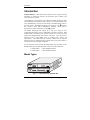
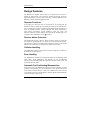
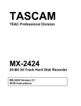
Congratulations on the purchase of your Kingston EtheRx WorkGroup (WG)
series 100BASE-TX Fast Ethernet hubs. There are two models available in this
series: KNE4TX/WG, which is the 4-Port model, and KNE8TX/WG, which is
the 8-Port model. The EtheRx Workgroup series hubs are Class II repeaters
that conform to IEEE 802.3u 100BASE-TX standards. Please refer to
Appendix D for further information on Class II repeaters.
The EtheRx Workgroup hubs support up to four (4) or eight (8) UTP
(Unshielded Twisted-Pair) ports for 100BASE-TX network connections. Both
models include a cascade switch on the last UTP port (Port 4 or Port 8) which
supports both straight-through and crossover cable types. The UTP ports use
dual-color LEDs to show three states of operation: link, activity and
partition/error. The EtheRx hubs also include a collision LED for collision
detection and five (5) utilization LEDs to display the level of network traffic in
percentages of the total available bandwidth.
For the remainder of this manual, the KNE4TX/WG (4-port model) and the
KNE8TX/WG (8-port model) hubs will be referred to as the EtheRx hubs.
• KNE4TX/WG
• KNE8TX/WG
4-Port 100BASE-TX Hub
8-Port 100BASE-TX Hub
Model Types
I00BASE-TX Class
1
12
25
LINK / ACTIVITY / PARTITION
50
1
COLL
60
I00BASE-TX Class
1
12
25
2
3
4
CASCADE
EtheRx Workgroup
Repeater
UTIL %
PWR
KNE8TX/WG
EtheRx Workgroup
Repeater
UTIL %
PWR
KNE4TX/WG
LINK / ACTIVITY / PARTITION
50
60
COLL
1
2
3
4
5
6
7
8
CASCADE
Fig. 1-1 – KNE4TX/WG & KNE8TX/WG
KNExTX/WG User’s Guide - Rev. A00
Kingston Technology Company
2
Introduction
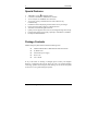
Special Features
•
•
•
•
•
•
•
•
•
•
100BASE-TX Class II compliant repeater
Conforms to IEEE802.3u 100BASE-TX standard
4 or 8 UTP ports for 100BASE-TX connections
4 or 8 Link, Activity, and Partition/Error status LEDs for easy
troubleshooting
Utilization LEDs for displaying network traffic rates in percentages
Power LED and Collision LED for collision detection
Automatic Port Partitioning/Reconnection
Uplink port that supports both crossover and straight-through cable wiring
External auto-sensing power supply operating at 100-240VAC (50/60Hz)
Desktop and Wall-mountable
Package Contents
EtheRx Workgroup hubs should contain the following items:
EtheRx KNE4TX/WG or KNE8TX/WG Fast Ethernet hub
(4) Rubber Feet
External DC power supply
Power cord
User’s Guide
If any of the items are missing or damaged, please contact your Kingston
dealer for a replacement. Be sure the items you receive are genuine Kingston
Technology products. If the Kingston name and logo are not on the front panel
of the unit, it’s not a genuine Kingston product.
Kingston Technology Company
KNExTX/WG User’s Guide - Rev. A00
Design Features
3
Design Features
The EtheRx hub complies with the full set of repeater basic functions as
defined by IEEE 802.3u. These functions include all Repeater Functions,
Signal Regeneration, Receive Jabber Protection, Collision-Handling, ErrorHandling, and Auto Partitioning/Reconnection.
Repeater Functions
If any single port senses the start of a valid packet on its receiving line, the
EtheRx hub will re-transmit the received data to all other ports on the network.
The re-transmission of packets complies with the IEEE 802.3u specification in
terms of preamble structure, voltage amplitude, and timing characteristics.
These timing regenerations prevent cumulative signal loss, jitters, and
distortion caused by network cabling, thus allowing the EtheRx hubs to be
cascaded to other 100BASE-TX Class II repeaters.
Receive Jabber Protection
The EtheRx hub provides a Receive Jabber Protection scheme to ensure that
the network is not disabled due to reception of excessively long data packets.
This protection scheme will automatically interrupt the receiver if the EtheRx
hub has been continuously receiving for more than 65,536-bit times.
Collision-Handling
The EtheRx hub will detect and respond to collision conditions as outlined in
the IEEE 802.3u specifications.
Error-Handling
The 100BASE-TX standard uses an improved method of error-handling called
block coding. With 100BASE-TX Fast Ethernet, the new error-handling
feature prevents substandard links from generating streams of false carrier and
interfering with other links.
Automatic Port Partitioning/Reconnection
If any of the ports on the EtheRx hub experience excessive collisions, or faulty
conditions, that particular port can be partitioned. Once partitioned, the hub
will continue to monitor that port. If the error conditions have been corrected
or a good data packet is received without a collision, the hub will automatically
reconnect that port to the network.
KNExTX/WG User’s Guide - Rev. A00
Kingston Technology Company
4
Front Panel
Hardware Installation
Before you begin installing network cables, please take a few moments to
familiarize yourself with the EtheRx hubs. The front and rear panels of the
Fast Ethernet Workgroup hubs are illustrated below.
Front Panel
Utilization LEDs
I00BASE-TX Class
UTP Port LEDs
EtheRx Workgroup
Repeater
UTIL %
PWR
KNE4TX/WG
1
12
25
LINK / ACTIVITY / PARTITION
50
Power LED
1
COLL
60
2
3
4
CASCADE
Collision LED
Cascade Switch
Fig. 1-2 KNE4TX/WG Front Panel
Utilization LEDs
I00BASE-TX Class
1
Power LED
12
25
EtheRx Workgroup
Repeater
UTIL %
PWR
KNE8TX/WG
UTP Port LEDs
LINK / ACTIVITY / PARTITION
50
60
COLL
1
Collision LED
2
3
4
5
6
7
8
CASCADE
Cascade Switch
Fig. 1-3 KNE8TX/WG Front Panel
Power LED
The green LED indicates the power status. The LED will light up when the unit
is properly connected to the accompanying DC power supply. For further
details, please refer to Figure 1-8 on page 8.
Kingston Technology Company
KNExTX/WG User’s Guide - Rev. A00
Front Panel
5
Utilization LEDs
The five Utilization LEDs display the rate of network traffic in percentages of
the total available bandwidth. The amount of data traffic is measured in frames
per second (FPS), then calculated into percentage values: 1%, 12%, 25%, 50%,
and > 60%. The appropriate LED will light up based on network activity.
Collision LED
If a collision is detected on the network, the Collision LED will flash amber. A
collision occurs when the hub receives data from two or more nodes
simultaneously.
4 or 8 UTP Port LEDs
The LINK/ACTIVITY/PARTITION LEDs use two colors to display three
states of operation for the 4 or 8 UTP ports. If a good link is established on any
given port, the LED will light up steady green, indicating a valid network
connection between the network node and the hub. If the LED does not
display solid green indicating a good link, check the following:
1.
Make sure the power is turned on for both the PC and EtheRx
hub.
2.
Verify the network adapter has loaded its drivers from the PC.
Some network adapters require the drivers to be loaded to
establish a proper link.
3.
Make sure the correct cable type is selected.
4.
Make sure the cable is wired properly and connected on both
ends.
5.
If steps 1 thru 4 are correct, the cable may be defective or not
wired correctly.
Please refer to Appendix A for pin
assignments and Appendix B for cabling guidelines.
A flashing green light indicates when data is being received. A flashing amber
light indicates one of the following occurences:
1.
A port has been partitioned due to an excessive number of
collisions or
2.
A port has encountered errors due to invalid packets or jabber
conditions.
KNExTX/WG User’s Guide - Rev. A00
Kingston Technology Company
6
Front Panel
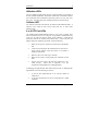
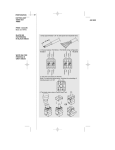
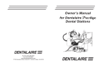
Cascade Switch
The Cascade Switch provides cable wiring flexibility on the last UTP Port (i.e.,
Port 4 or Port 8) for connecting to a workstation or cascading to another hub.
By default, the last UTP port is set to “Crossover” (left side) as a standard,
internally-crossed port, or MDI-X port. Depending on the wiring of your UTP
cable (normally “Straight-Through”), the port is used to connect a workstation.
For cascading to another Class II repeater using a straight-through cable,
move the Cable Switch to “Straight-Through” (right side). If a crossover UTP
cable is used to cascade to another Class II repeater, leave the Cable Switch in
the “Crossover” position. See Figure 1-4 for a diagram showing the cascade
switch settings. To verify the pin wiring of your UTP cable, refer to
“Appendix B Cabling Guidelines” on page 11.
Using a Straight-Through Cable
Rx Workgroup
CASCADE
Leave the cascade switch
in the default crossover
(MDI-X) position when
connecting the last UTP
port (port 4 or port 8) on
the EtheRx Hub to a
network card or router (or
other MDI-configured
device.)
Rx Workgroup
CASCADE
Move the cascade switch
to the straight-through
position when connecting
the last UTP port (port 4
or port 8) on the EtheRx
Hub to another Class II
repeater (or other MDI-X
configured device.)
Using a Crossover Cable
Rx Workgroup
CASCADE
Leave the cascade switch
in the default crossover
(MDI-X) position when
connecting the last UTP
port (port 4 or port 8) on
the EtheRx Hub to another
Class II repeater (or other
MDI-X configured device.)
Rx Workgroup
CASCADE
Move the cascade switch
to the straight-through
position when
connecting the last UTP
port (port 4 or port 8) on
the EtheRx Hub to a
network card or router
(or other MDI-configured
device.)
Fig. 1-4 Cascade Switch functions
Notes on MDI and MDI-X Ports
MDI (Media Dependent Interface) is the IEEE 802.3 standard for the interface
to the UTP cable. For two 100BASE-TX devices to communicate with each
other, the transmitter of one device must be connected to the receiver of the
other device. This can be achieved by using a crossover cable, or by using one
MDI-X port that implements the cross-over internally.
Kingston Technology Company
KNExTX/WG User’s Guide - Rev. A00
Front Panel
7
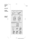
Port 1 through Port 3 (or 7) respectively, like all normal hub ports, are
configured MDI-X, whereas the last UTP ports, Port 4 or Port 8, support both
port configurations, MDI and MDI-X. All NICs (Network Interface Cards) and
Router ports are usually by default configured MDI. A simple illustration
shows the relationship of cable types to port types:
Switch
Position
Port
Config
For Connection to
another Hub Port (MDI-X)
For Connection to a
Network Adapter (MDI)
MDI-X
Use Crossover cable
Use Straight-through cable
MDI
Use Straight-through cable
Use Crossover cable
Table 1-1 Cascade Switch functions
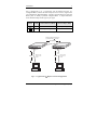
Maximum cable length between two
(2) cascaded Class II repeaters
5m (16.4ft)
~
~
I00BASE-TX Class
1
12
25
EtheRx Workgroup
Repeater
UTIL %
PWR
KNE8TX/WG
I00BASE-TX Class
60
COLL
Class
100m
1
II
~
~
2
3
4
5
6
7
8
CASCADE
KNE8TX/WG
repeater
12
25
LINK / ACTIVITY / PARTITION
50
60
COLL
Class
Maximum cable
length from hub
to node.
100m
Node
Fig. 1-5 - Typical Class
1
EtheRx Workgroup
Repeater
UTIL %
PWR
LINK / ACTIVITY / PARTITION
50
1
II
2
3
4
5
6
7
8
CASCADE
repeater
~
~
Maximum cable
length from hub
to node.
Node
II
Repeater Cascade Configuration
KNExTX/WG User’s Guide - Rev. A00
Kingston Technology Company
8
Rear Panel
Rear Panel
5V
4
3
2
2A
1
Fig. 1-6 KNE4TX/WG Rear Panel
5V
8
7
6
5
3
4
2
2A
1
Fig. 1-7 KNE8TX/WG Rear Panel
4 or 8 UTP Ports
The UTP ports are numbered 1 through 4 or 1 through 8 for 100BASE-TX
connections. Since crossover function is implemented on all UTP MDI-X
ports, a straight-through UTP cable should be used. (Note: Port 4 and Port 8
support both cable types using the cascade switch. Refer to Appendix A & B
for details on RJ-45 pin assignments and cable guidelines.
DC Power Connector
The EtheRx hub gets its power from the auto-sensing power supply. Insert the
power jack into the DC power connector located to the far right. For safety
purposes, ONLY use the included power supply for proper operation. The
wrong type of power supply may cause damage to both the EtheRx hub and the
power supply. (NOTE: The power supply output voltage is 5VDC/2.0A.
Polarity on the power jack and DC power connector is negative (-) on the
outside and positive (+) on the inside.)
Rear Panel View
5V
2A
DC Power Jack
DC Power Connector
Fig. 1-8 DC Power Connector
Kingston Technology Company
KNExTX/WG User’s Guide - Rev. A00
Appendices
9
Appendices
KNExTX/WG User’s Guide - Rev. A00
Kingston Technology Company
10
Appendix A
Appendix A
Pin Assignments
Pin Assignments
UTP Pin Assignments
UTP Ports use RJ-45 Unshielded Twisted Pair (UTP) cabling. Cable Pin
Numbers and Pin Wiring Assignments are listed below in Figure A-1 and Table
A-2, respectively. Twisted-Pair cables can be wired with either StraightThrough or Crossover pin assignments. Both wiring schemes are mentioned in
"Appendix B Cabling Guidelines" for reference in creating a twisted-pair cable.
5V
3
2
2A
1
1 2 3 4 5 6 7 8
Fig. A-1 RJ-45 Connector Pin Numbers
Pin Number
Function
1
Transmit Data +
2
Transmit Data -
3
Receive Data +
4,5
Not Used
6
Receive Data -
7,8
Not Used
Table A-1 UTP Pin Assignments
Kingston Technology Company
KNExTX/WG User’s Guide - Rev. A00
Appendix B
Cabling Guidelines
Appendix B
11
Cabling Guidelines
UTP Cable Wiring
100BASE-TX unshielded twisted-pair cables can be wired as "StraightThrough" or, in some cases, "Crossover" depending on the application. For
workstations connected to a hub, use "Straight-Through' wiring illustrated in
Table B-1. In some instances, you may want to use "Crossover" wiring
illustrated below in Table B-2.
"Straight-Through"
Cable Wiring
Crossover”
Cable Wiring
Pin Number
Pin Number
Pin Number
Pin Number
1 (TRX +)
1 (TRX +)
1 (TRX +)
3 (RCV +)
2 (TRX -)
2 (TRX -)
2 (TRX -)
6 (RCV -)
3 (RCV +)
3 (RCV +)
3 (RCV +)
1 (TRX +)
6 (RCV -)
6 (RCV -)
6 (RCV -)
2 (TRX -)
4, 5, 7, 8
Not Used
4, 5, 7, 8
Not Used
Table B-1. Straight-Through Wiring
Table B-2. Crossover Wiring
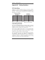
Cable Wiring Standards
There are two governmental agencies: the Electronic Industry Association
(EIA) and the Telecommunications Industry Association (TIA), which set the
standard for all cable wiring requirements for commercial buildings. For
100BASE-TX networks, Category (CAT) 5 should be used.
With the advent of 100Mbit network products, it is best to use higher quality
CAT 5 cables like Belden or Helix as well as CAT 5-compliant patch panels
and connectors while following the EIA/TIA wiring standards. 100 Ohm
UTP/STP CAT 3, 4 & 5 type cables use 4-pair UTP wiring.
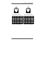
Refer to the illustrations on page 12 for standard 100BASE-TX wiring and 4pair 100Mbit wiring using either T568A (Table B-3) or T568B (Table B-4)
wiring standards. Both T568A and T568B wiring configurations are
compatible with 10BASE-T and 100BASE-TX and require no special hardware
configurations. However, it is highly recommended that only one wiring
scheme be used in premise wiring to avoid potential problems.
KNExTX/WG User’s Guide - Rev. A00
Kingston Technology Company
12
Appendix B
Cabling Guidelines
Pair 2
Pair 3
Pair 3 Pair 1 Pair 4
Pair 2 Pair 1 Pair 4
12345678
12345678
T568A
T568B
Fig. B-1 4-Pair T568A Wiring
Fig. B-2 4-Pair T568B Wiring
T568A
Pairs
Strand
T568B
Pairs
Strand
Solid
Pin 1
Pair 3
Blue
White/Green
Solid
Pin 1
Pair 2
Black
White/Orange
Pin 2
Pair 3
Orange
Green/White
Pin 2
Pair 2
Yellow
Orange/White
Pin 3
Pair 2
Black
White/Orange
Pin 3
Pair 3
Blue
White/Green
Pin 4
Pair 1
Red
Blue/White
Pin 4
Pair 1
Red
Blue/White
Pin 5
Pair 1
Green
White/Blue
Pin 5
Pair 1
Green
White/Blue
Pin 6
Pair 2
Yellow
Orange/White
Pin 6
Pair 3
Orange
Green/White
Pin 7
Pair 4
Brown
White/Brown
Pin 7
Pair 4
Brown
White/Brown
Pin 8
Pair 4
White
Brown/White
Pin 8
Pair 4
White
Brown/White
Table B-3 4-Pair T568A Wiring
Kingston Technology Company
Table B-4 4-Pair T568B Wiring
KNExTX/WG User’s Guide - Rev. A00
Appendix B
Cabling Guidelines
13
Rating Codes
UTP cables meet different UL-NEC requirements based on cable-jacket
quality. Below is an explanation of the rating codes for each cable type.
UL – The National Electrical Code (NEC), published by the National Fire
Protection Association (NFPA), details advisory safety considerations for
electrical wiring. NEC Article 800 Communications Cables are manufactured
to meet these different cable types.
1.
CMP – Cables meeting type CMP requirements are suitable for
installation in ducts and plenums without the use of conduit. These cables
are designed for fire resistance and low-smoke producing characteristics.
2.
CMR – Riser type cables are engineered to prevent the spread of fire from
floor to floor and are suitable for vertical shaft applications.
3.
CM – Cables for general building wiring. CM cables are used in areas
other than plenums and risers. These cables are resistant to the spread of
fire and pass the UL 1581Vertical Tray Flame Test.
4.
MP, MPR & MPP – Within Article 800, the Multi-purpose Cables
Category, allows conditional substitutions between different cable types &
are restricted by number, AWG size and stranding of the cable
conductors.
Terms You Should Be Familiar With
1.
BACKBONE WIRING – The physical/electrical interconnections
between telecommunications closets and equipment rooms.
2.
COMPLIANCE – A wiring device that meets all characteristics of a
standard is said to be in compliance with that standard.
3.
TWISTED PAIR (UTP) – Two insulated copper wires twisted around
each other to reduce interference from one wire to the other. The twists
are varied in length to reduce the potential for signal interference between
pairs. Several sets of twisted pair wires may be enclosed in a single cable.
KNExTX/WG User’s Guide - Rev. A00
Kingston Technology Company
14
4.
Appendix B
Cabling Guidelines
NEAR-END CROSSTALK (NEXT) – In wires packed together within a
cable, the signals generated at one end of the link can flush out the weaker
signals coming back from the recipient.
Appendix C
Specifications
EtheRx 4- and 8-Port Fast Ethernet Workgroup Hubs
Compliance:
Media Interface:
KNE4TX/WG
KNE8TX/WG
Diagnostic LEDs:
1 LED for each port
Connection Type:
Cable Type:
Maximum Cable Length:
Cascading 2 Class II
repeaters (2 max.):
Repeater to node:
Environmental:
Operating Temp.
Storage Temp.
Relative Humidity
Electrical:
Input Voltage:
Output Voltage:
Power Polarity:
Power Consumption:
KNE4TX/WG
KNE8TX/WG
Physical:
Dimension (HxWxD):
Weight:
Certification:
Kingston Technology Company
IEEE 802.3u 100BASE-TX Standard
4 UTP ports for 100Mbps connections
8 UTP ports for 100Mbps connections
1 LED for Power Indicator (steady green)
5 LEDs for Utilization status (steady green)
1 LED for Collision Detection (flashing amber)
Link (steady green)
Activity (flashing green)
Partition / Error (flashing amber)
RJ-45, Female
Category 5 UTP 26 to 22 AWG
5m (16.4ft)
100m (328ft)
0°C to 45°C (32°F to 113°F)
-20°C to 60°C (-4°F to 140°F)
10% to 90% non-condensing
100VAC-240VAC, 50/60Hz
Auto-sensing
5VDC, 2A
4.5W
8.5W
1.1” (28mm) x 6.5” (165mm) x 6.1” (155mm)
1.9 lbs (0.86 kg)
KNExTX/WG User’s Guide - Rev. A00
Appendix D
Commonly Asked Questions
EMI Standards:
EMC Standards:
Low Voltage Directive:
15
FCC Class A, CE CISPR A
EN55022, IEC801-2, IEC801-3, IEC801-4
EN60950
KNExTX/WG User’s Guide - Rev. A00
Kingston Technology Company
16
Appendix D
Appendix D
Commonly Asked Questions
Commonly Asked Questions
Class I vs. Class II 100BASE-TX Fast Ethernet Repeaters
There are currently two classes of Fast Ethernet repeaters, defined as Class I
and Class II .
Class I : in a maximum length segment topology, only one Class
I repeater may exist between any two nodes within a single
collision domain.
Class II : in a maximum length segment topology, two Class II
repeaters may exist between any two nodes within a single collision
domain.
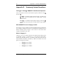
Will 100BASE-TX run on Category 3 cable?
No! Category 3 (CAT 3) cabling even in short lengths generates too much near
end crosstalk for 100BASE-TX networks. The IEEE 802.3u 100BASE-TX Fast
Ethernet standard requires Category 5 100 Ω UTP or 150 Ω STP which
complies with ISO/IEC 11801:1995.
What is Category 5?
Category 5 (CAT 5) is a further extension of the EIA/TIA-568 cabling system
to 100 MHz. Category 5 components (i.e., UTP trunk and patch cables,
modular plug, and patch panel, etc.) are defined by EIA/TIA-568, but with the
characterizations extended to 100 MHz by TSB-36 and TSB-40. The cable
grades are categorized as follows:
•
Category 3: up to 16 MHz
•
Category 4: up to 20 MHz.
•
Category 5: up to 100 MHz.
Kingston Technology Company
KNExTX/WG User’s Guide - Rev. A00
Appendix D
Commonly Asked Questions
17
Category 5 Compliance vs. Category 5 Performance?
Having CAT 5 components in your network installation does not necessarily
achieve full Category 5 performance. To achieve any category-rated
performance, make sure all cabling components are at least of the minimum
category required.
To achieve full CAT 5 performance, all components must be CAT 5 compliant
and terminated properly according to EIA/TIA-568 TSB-36 and TSB-40
guidelines.
What are the Guidelines for Proper Termination?
It is important to maintain the twists of the cable as close to the termination on
the outlet as possible, to avoid NEXT (Near End Cross Talk) and to maintain
the transmissions characteristics of the Category. Category specifications
require that pair twisting be maintained to within the following distances from
the outlet termination:
•
Category 3 maximum allowed untwisting: 3 inches
•
Category 4 maximum allowed untwisting: 1 inch
•
Category 5 maximum allowed untwisting: 1/2 inch
Can I mix CAT 3 and CAT 5 cabling in the same building?
Yes, but keep in mind, you will not have CAT 5 performance. It is a good idea
to keep the lines separated when installing any new lines. Use CAT 5 UTP
cabling only.
Can a Four-Pair CAT 5 cable support two 100BASE-TX
devices?
Although only two pairs are used in the standard four-pair CAT 5 UTP cable, it
is not recommended because it exceeds the specifications outlined by IEEE
802.3u.
Appendix E
Mounting Templates
KNExTX/WG User’s Guide - Rev. A00
Kingston Technology Company
18
Appendix D
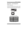
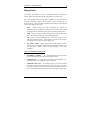
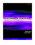
Mounting Templates
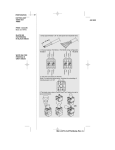
The EtheRx WorkGroup hubs can be stationed on a flat surface using the four
rubber feet provided, or mounted vertically by using the mounting holes on the
bottom side of the unit. The illustrations below detail the measurements and
mounting holes and rubber feet locations. They are drawn to scale, although
not actual size.
Front Panel
1.08"
Wall Mount Holes
4.28"
2.95"
5.95"
Rubber Feet
Rubber Feet
Rear Panel
6.44"
Front Panel
Rubber Feet
This device complies with Part 15 of the FCC rules.
Operation is subject to the following two conditions.
(1) This device may not cause harmful interference, and
(2) This device must accept any interference received;
including interference that may cause undesired
operation.
Models:
KNE4TX/WG
KNE8TX/WG
5.95"
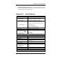
Operation & Configuration Instructions
UTP PORT STATUS LEDs (3-State)
Good link is established
Data is being received
SOLID GREEN
FLASH GREEN
1. Port is partitioned due to excessive collisions, or
2. Port has encountered errors due to invalid packets or
jabber condition
FLASH AMBER
COLLISION STATUS LED
Collision is detected
FLASH AMBER
UTILIZATION STATUS LEDs
Network traffic rate is displayed in percentage
SOLID GREEN
SWITCH
POSITION
PORT
CONFIG.
FOR CONNECTION TO
ANOTHER MDI-X HUB PORT
FOR CONNECTION TO A
NETWORK ADAPTER OR ROUTER
MDI-X
Use cross-over cable
Use straight-through cable
MDI
Use straight-through cable
Use cross-over cable
P/N: 5550147-001.A00
2.95"
PORT-4 OR PORT-8 CABLE-SELECTION SWITCH
For more detailed information, please refer to the User's Guide provided.
Rubber Feet
Rear Panel
6.44"
Fig. E-1 Mounting Template specifications
Kingston Technology Company
KNExTX/WG User’s Guide - Rev. A00
Appendix F
Warranties and Notices
Appendix F
19
Warranties and Notices
Limited Warranty Statement
KINGSTON TECHNOLOGY COMPANY ("Kingston") warrants that this product is free
from defects in material and workmanship. Subject to the conditions and limitations set
forth below, Kingston will, at its option, either repair or replace any part of this product
which proves defective by reason of improper workmanship or materials. Repair parts or
replacement products will be provided by Kingston on an exchange basis, and will be
either new or refurbished to be functionally equivalent to new.
This warranty does not cover any damage to this product which results from accident,
abuse, misuse, natural or personal disaster, or any unauthorized disassembly, repair or
modification.
Duration of Warranty
Lifetime Warranty: The following Kingston products are covered by this warranty for
life: solid state memory (e.g., memory modules and boards), networking adapters,
networking hubs without cooling fans (excluding the power supply), solid state PC Card
(PCMCIA) adapters, and microprocessor upgrade products.
Seven Year Warranty: The following Kingston products are covered by this warranty for
a period of seven years from the date of original retail purchase: storage enclosures
(including the power supply), cables, terminators, and accessories.
Five Year Warranty: The following Kingston products are covered by this warranty for
a period of five years from the date of original retail purchase: the power supply in
networking hubs without cooling fans; and all other Kingston products (other than those
products covered by a three-year, two-year, or one-year warranty, as provided below).
Three Year Warranty: The following Kingston products are covered by this warranty for
a period of three years from the date of original retail purchase: networking hubs with
cooling fans (including the power supply).
Two Year Warranty: The following Kingston products are covered by this warranty for a
period of two years from the date of original retail purchase: Solid State Floppy Disk
Cards (SSFDC), and Winchester hard disk drives in a 2.5 inch, 3.5 inch or 5.25 inch form
factor.
One Year Warranty: The following Kingston products are covered by this warranty for a
period of one year from the date of original retail purchase: Winchester hard disk drives
in a 1.8 inch form factor, optical storage products, and magnetic tape storage products.
KNExTX/WG User’s Guide - Rev. A00
Kingston Technology Company
20
Appendix F
Warranties and Notices
Warranty Claim Requirements
To obtain warranty service, return the defective product, freight prepaid and insured, to
your local authorized Kingston dealer or distributor, or to the Kingston factory service
center located at 17600 Newhope Street, Fountain Valley, California 92708, U.S.A. You
must include the product serial number (if applicable) and a detailed description of the
problem you are experiencing. You must also include proof of the date of original retail
purchase as evidence that the product is within the applicable warranty period. If you
return the product directly to the Kingston factory, you must first obtain a Return
Material Authorization ("RMA") number by calling Kingston Customer Service at
(714) 438-1810, and include the RMA number prominently displayed on the outside of
your package. Products must be properly packaged to prevent damage in transit.
Free Technical Support
Kingston provides free technical support. If you experience any difficulty during the
installation or subsequent use of a Kingston product, please contact Kingston’s Technical
Support department prior to servicing your system.
Kingston Technical Support can be reached in the U.S. at (714) 435-2639 or toll-free at
(800) 435-0640 (U.S. and Canada only). Kingston European Technical Support can be
reached from within the U.K. at 01932 738858. Kingston provides other service numbers
when calling from Germany 0130 115 639 or fax 0130 860 599, from Austria 0660 5569
or fax 06 607 434, from Switzerland 0800 557 748 or fax 0800 552 182, from France
0800 905 701 or fax 0800 900 910, or from Belgium (in English) 0800 72763.
This warranty covers only repair or replacement of defective Kingston products, as
provided above. Kingston is not liable for, and does not cover under warranty, any costs
associated with servicing and/or the installation of Kingston products.
Disclaimers
The foregoing is the complete warranty for Kingston products and supersedes all
other warranties and representations, whether oral or written. Except as expressly
set forth above, no other warranties are made with respect to Kingston products and
Kingston expressly disclaims all warranties not stated herein, including, to the
extent permitted by applicable law, any implied warranty of merchantability or
fitness for a particular purpose. In no event will Kingston be liable to the
purchaser, or to any user of the Kingston product, for any damages, expenses, lost
revenues, lost savings, lost profits, or any other incidental or consequential damages
arising from the purchase, use or inability to use the Kingston product, even if
Kingston has been advised of the possibility of such damages.
Rev. 10/97
Copyright © 1997 Kingston Technology Company. All rights reserved. Printed in the U.S.A. Kingston Technology
and the Kingston logo are trademarks of Kingston Technology Company.
Kingston Technology Company
KNExTX/WG User’s Guide - Rev. A00
Appendix F
Warranties and Notices
19
F.C.C. Certification
This device has been tested and found to comply with limits for Class A digital
device, pursuant to Part 15 of the FCC Rules. Operation is subject to the
following two conditions:
(1) This device may not cause harmful interference, and
(2) This device must accept any interference received;
including interference that may cause undesired
operation.
CE Notice
The official CE symbol indicates compliance of this Kingston Technology
product to the EMC directive of the European Community. The CE symbol
found here or elsewhere indicates that this Kingston product meets or exceeds
the following standards:
❑ EN50081-1
“Electromagnetic Compatibility-generic emissions
standard”
EN55022: “Limits and methods of measurement of radio
interference characteristics.”
❑ EN50082-1
“Electromagnetic Compatibility-generic immunity
standard”
IEC 801-2: “Electrostatic discharge requirements”
IEC 801-3: “Radiated immunity requirements”
IEC 801-4: “Electrical fast transient requirements”
❑ EN60950
“Low Voltage Directive (LVD)”
❑ Declaration of CE Conformity in accordance with the above standards
has been made and is on file at Kingston Technology.
KNExTX/WG User’s Guide - Rev. A00
Kingston Technology Company