1
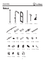
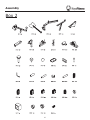
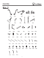
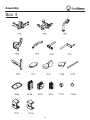
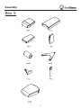
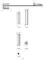
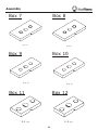
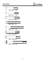
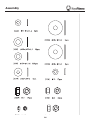
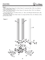
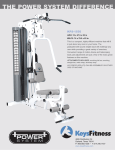
Owner’s Manual
215-00132
11/06 Rev A
KF-2060
Table of Contents
Before You Start
3
Important Safety Information
4
Assembly
5-40
Weight Ratios
41
Weight Stack Sticker Placement
42
Cable View
43
Top View
44
Exploded View
45
Parts List
46
Warranty Information
47
Before You Start
THANK YOU for making this unit a part of your exercise program.
Keys Fitness assures the very best in value, appearance, durability
and biomechanics.
This manual will guide you through the assembly process. If at any
time you are having trouble with the assembly or use of this product, then
please contact us at our Keys Fitness Helpline. We have trained service technicians on site to take care of you, our valued customer.
REGISTRATION CARD
To avoid unnecessary delays in warranty parts and to insure that a permanent
record of your purchase is on file with our company, be sure to send in the warranty registration card or register on-line at www.keysfitness.com within 10 days
of purchase.
KEYS FITNESS Series
QUESTIONS?
CALL
1-888-380-0482
M on d a y - F r i d a y
8:30- 5 : 3 0 C e n tr a l T i m e
When calling please have the following product information available:
Model Name : KF-2060
Serial #:
Manufactured Date :
PO # :
Model Name Decal Location
Important Safety Information
Prior to assembly, remove components from the box and verify that all the listed parts were
supplied.
NOTE: Hand tighten bolts and nylon nuts until machine is fully assembled.
Read all precautions and instructions in this manual before using this equipment.
WARNING!
efore using this unit or starting any exercise program, consult your
B
physician. This is especially important for persons over the age of
35 and/or persons with pre-existing health problems. Keys Fitness
Products LP assumes no responsibility for personal injury or property
damage sustained by or through the use of this product.
It is the owner’s responsibility to ensure that all users of this unit
have read the Owner’s Manual and are familiar with safety information and precautions.
SAFETY PRECAUTIONS
•T
his unit should only be used on a level surface and is intended for
indoor use only. Keys Fitness recommends an equipment mat be
placed under the unit to protect the floor or carpet and for easier
cleaning.
•W
ear comfortable, good-quality walking or running shoes and
appropriate clothing. Do not use this unit with bare feet, sandals,
socks or stockings!
•A
lways examine your unit before using to ensure all parts are in
working order.
• Do not leave children unsupervised near or on the unit.
•S
ervice to your unit should only be performed by an authorized
service representative, unless authorized and/or instructed by a
Keys Fitness technician. Failure to follow these instructions will void
the warranty.
Assembly
Box 1
Assembly
Box 2
Assembly
Box 3
Assembly
Box 4
Assembly
Box 5
Assembly
Box 6
10
Assembly
Box 8
Box 7
【52】5pcs
【52】5pcs
Box 9
Box 10
【53】9pcs
【53】9pcs
Box 11
Box 12
【54】5pcs
【54】5pcs
11
Assembly
12
Assembly
13
Assembly
14
Assembly
Step 1
Attach Right Base Frame (4) to Rear Frame (1) using two Nuts (144), four Washers
(143), and two Bolts (137).
Attach Left Base Frame (8) to Rear Frame (1) using two Nuts (144), four Washers
(143), and two Bolts (137).
Insert Guide Rods (47) into Rear Frame (1). Next, slide Weight Stack Bumpers (99)
onto Guide Rods (47).
Attach Rear Upright (3) to Rear Frame (1) using two Nuts (144), four Washers (143),
and two Bolts (136).
Figure 1
15
Assembly
Step 2
Slide the weight plates down the Guide Rods (47) in this order - five 15lb Plates (52), nine
10lb Plates (53), five 5lb Plates (54), and the Top Plate (55). Note: Number of weight plates
may vary depending on your specific configuration.
Attach Top Frame (2) to all four Guide Rods (47) and secure to Rear Upright (3) using two
Nuts (144), four Washers (143), and two Bolts (136).
Figure 2
16
Assembly
Step 3
Attach Front Upright (19) to Seat Pad Support Receptacle (6) using two Nuts (144), four
Washers (143), and two Bolts (136).
Attach Seat Pad Support Receptacle (6) to Base Frame assembly using two Nuts (144), four
Washers (143), and two Bolts (136).
Figure 3
17
Assembly
Step 4
Attach Main Upright (7) to Seat Pad Support Receptacle using two Nuts (126), four Washers
(125), and two Bolts (131).
Attach Right Top Frame (5) to Top Frame assembly using two Nuts (144), four Washers (143),
and two Bolts (137). Next, use two Washers (143), two Spring Washers (119), and two Bolts
(142) to connect Right Top Frame (5) to Main Upright.
Figure 4
18
Assembly
Step 5
Slide Press Station Base Frame (11) over Press Arm Support (10). Next, attach both pieces
to Base Frame using two Nuts (144), four Washers (143), and two Bolts (134).
Install Left Top Frame over Press Arm Support (10) and Top Frame assembly. Secure top
section using two Nuts (144), four Washers (143), and two Bolts (137). Next, Secure lower
section using two Nuts (144), four Washers (143), and two Bolts (136). Secure top of Guide
Rods (47) using two Washers (143), two Spring Washers (119), and two Bolts (142).
Figure 5
19
Assembly
Step 6
Attach Pec Dec Mount (21) onto Seat Pad Support Receptacle using two Nuts (144), four
Washers (143), and two Bolts (136). Secure in place with one Washer (129), one Spring
Washer (119), and one Bolt (137).
Figure 6
20
Assembly
Step 7
Attach Right and Left Leg Hold Leg Frames (29 & 30) using two Nuts (144), four Washers
(143), and two Bolts (135).
Figure 7
21
Assembly
Step 8
Slide the Right Pec Dec Arm (22) on to the shaft of the Pec Dec Mount. Secure the arm in
place using one Big Washer (102), one Washer (143), one Spring Washer (119), and one Bolt
(128).
Slide Pec Dec Handle Bar (24) onto the top of the Right Pec Dec Arm (22) and secure using
one Chrome Washer (101), one Washer (143), one Spring Washer (119), and one Bolt (128).
Repeat this step to complete the Left Pec Dec assembly.
Figure 8
22
Assembly
Step 9
Attach Leg Extension Lever (20) to Seat Pad Support Receptacle (6) and secure using Shaft
(86), one Washer (117), one Spring Washer (118), and one Allen Bolt (98).
Slide Foam Frame w/ Shaft (26) through the Leg Extension Lever (20) and attach Foam
Frame w/o Shaft (25) to the other side. Insert Slip Tension Pin (85) through the hole where
the two foam frames meet.
Note: You may need to use a rubber mallet to install Slip Tension Pin (85).
Figure 9
23
Assembly
Step 10
Align Press Arm (35) and Chest Press Cam (12) while inserting Press Station Shaft (38). Slide
Pillow Block Bearing (75) onto each side of Press Station Shaft (38) and secure the assembly
using two Chrome Washers (101), two Washers (143), two Spring Washers (119), and two Allen
Bolts (128).
Attach the entire assembly to Press Arm Support using four Nuts (126), eight Washers (125),
and four Bolts (130).
Figure 10
24
Assembly
Step 11
Attach Bench Rear Frame (15) onto Bench Main Frame (13) and secure using two Nuts (144),
four Washers (143), and two Bolts (133).
Attach Bench Front Stabilizer (14) on to Bench Main Frame (13) using two Nuts (144), four
Washers (143), and two Bolts (136).
Figure 11
25
Assembly
Step 12
Attach Bench Seat Pad Support (16) to Bench Main Frame using one Nut (126), two Washer
(125), and one Bolt (132).
Insert Bench Seat Pad Adjustment Bar (64) into Bench Main Frame and secure using one
Washer (125) and one Nut (126). Attach Spring (66) to Bench Main Frame and Bench Seat
Pad Adjustment Bar (64).
Note: Make sure adjustment bar is installed into adjustable slots on Bench Seat Pad
Support.
Figure 12
26
Assembly
Step 13
Attach Bench Back Pad Support (17) to Bench Main Frame using one Nut (126), two Washers
(125), and one Bolt (132).
Attach Bench Back Pad Adjustment Frame (39) to Bench Back Pad Support (17) using one
Nut (126), two Washers (125), and one Bolt (132).
Figure 13
27
Assembly
Step 14
Attach Bench Seat Pad (48), Bench Lower Back Pad (156) and Bench Back Pad (49) using six
Washers (143) and six Bolts (138).
Insert Foam Shaft (40) into Foam Adjustable Bracket (18). Next, attach Upholstered Roller
Pads (58) using the following hardware: four Plastic Washers (90), two Chrome Washers (101),
two Washers (143), two Spring Washers (119), and two Bolts (128).
Figure 14
28
Assembly
Step 15
Attach Left and Right Squat Arms (36 & 37) to the Press Arm Assembly (35) using two Safety
Pins (73).
Next, slide Upholstered Roller Pad (58) onto each Squat Arm (36 & 37) and secure using two
Plastic Washers (90), two Chrome Washers (101), two Washers (143), two Spring Washers
(119), and two Bolts (128).
Figure 15
29
Assembly
Step 16
Attach Back Pad (51) to Back Pad Adjustment Bracket (28) using two Washers (143) and two
Bolts (127).
Attach Seat Pad (50) to Seat Pad Support (27) using two Washers (143) and two Allen Bolts
(127).
Slide both assemblies into receptacles as shown in Figure 16.
Figure 16
30
Assembly
Step 17
Slide two Upholstered Roller Pads (58) onto Foam Frames and secure using two Big Plugs
(89).
Slide the Long Foam Tube (34) through the hole in Seat Pad Support. Next, slide two Plastic
Washers (90), two Upholstered Roller Pads (58), and two Big Plugs (89) onto each end of Long
Foam Tube (34).
Next, slide two Upholstered Roller Pads (58) onto each side of Leg Hold Frames and secure
using two Big Plugs (89).
Figure 17
31
Assembly
Step 18
Note: Stretch all cables out completely and make sure all twisting is removed before
installing.
Install Lat Cable (110) as detailed in Figure 18. Follow dotted lines to identify exact location
of pulleys. See Page 43 “Cable View” for more detail.
Start by threading cable end into Top Plate (55).
You will need the following for installation:
Pulley (57) - Qty. 7
Bolt (134) - Qty. 2
Cable (110) - Qty. 1
Bolt (135) - Qty. 1
Nut (144) - Qty. 7
Bolt (136) - Qty. 1
Long Pulley Spacer (123) - Qty. 4
Bolt (137) - Qty. 1
Longer Pulley Spacer (121) - Qty. 4
Bolt (141) - Qty. 2
Washer (143) - Qty. 14
Figure 18
32
Assembly
Step 19
Note: This step is only used if you do not have the Leg Press 3 attachment. If you do have
Leg Press 3 attachment, please follow instructions located in that manual. Use the Cable
Adapter (124) in place of the pulley.
Note: Stretch all cables out completely and make sure all twisting is removed before
installing.
Install Leg Press Cable Substitute (113) as detailed in Figure 19. Follow dotted lines to
identify exact location of pulleys.
You will need the following for installation:
Cable Adapter (124) - Qty. 1
Pulley Bracket with Shaft (33) Qty. 1
Cable (113) - Qty. 1
Bolt (139) - Qty. 1
Washers (143) - Qty. 2
Nylon Locknut (143) - Qty. 1
Nut (144) - Qty. 1
Figure 19
33
Assembly
Step 20
Note: Stretch all cables out completely and make sure all twisting is removed before
installing.
Install Low Row Cable (111) as detailed in Figure 20. Follow dotted lines to identify exact
location of pulleys. See Page 43 “Cable View” for more detail.
Start by installing cable under the pulley at Leg Extension location.
You will need the following for installation:
Pulley (57) - Qty. 6
Bolt (134) - Qty. 1
Cable (111) - Qty. 1
Bolt (136) - Qty. 1
Nut (144) - Qty. 6
Bolt (137) - Qty 1
Long Pulley Spacer (123) - Qty. 4
Bolt (138) - Qty. 1
Longer Pulley Spacer (121) - Qty. 2
Bolt (141) - Qty. 2
Short Pulley Spacer (122) - Qty. 2
Washer (143) - Qty. 12
Cable Retainer Bracket (46) - Qty. 1
Figure 20
34
Assembly
Step 21
Note: Stretch all cables out completely and make sure all twisting is removed before installing.
Install Pec Dec Cable (112) as detailed in Figure 21. Follow dotted lines to identify exact
location of pulleys.
See Page 43 “Cable View” for more detail.
You will need the following for installation:
Cable (112) - Qty. 1
Pulley (57) - Qty. 3
Bolt (141) - Qty. 3
Washer (143) - Qty. 6
Nut (144) - Qty. 3
Philips Screw (103) - Qty. 2
Figure 21
35
Assembly
Step 22
Note: Stretch all cables out completely and make sure all twisting is removed before
installing.
Install Long Chest Cable (114) as detailed in Figure 22. Follow dotted lines to identify exact
location of pulleys. See Page 43 “Cable View” for more detail.
Start by installing cable into the “Press Station” weight stack.
You will need the following for installation:
Pulley (57) - Qty. 2
Cable (114) - Qty. 1
Nut (144) - Qty. 3
Washer (134) - Qty. 4
Bolt (141) - Qty. 3
Figure 22
36
Assembly
Step 23
Note: Stretch all cables out completely and make sure all twisting is removed before
installing.
Install Short Chest Cable (115) as detailed in Figure 23. Follow dotted lines to identify exact
location of pulleys. See Page 43 “Cable View” for more detail.
Start by threading the cable into the floating pulley bracket.
You will need the following for installation:
Pulley (57) - Qty. 1
Cable (115) - Qty. 1
Nut (144) - Qty. 2
Washer (134) - Qty. 2
Bolt (141) - Qty. 2
Figure 23
Floating
Pulley
37
Assembly
Step 24
Connect Long Lat Bar (43) to the Lat Cable (110) using two Gear Hooks (87) and Short Chain
(88).
Connect Ab Strap (60) or Lat Strap (61) to Low Row Cable (111) using one Gear Hook (87).
Connect Short Lat Bar (44) or Ankle Strap (62) to Low Row Cable (111) using two Gear
Hooks (87) and Long Chain (116).
Figure 24
38
Assembly
Step 25
Install Weight Shrouds (41) to the left and right side of the weight stacks using four Washers
(117) and four Bolts (98).
Install Weight Shroud (42) to the center of both weight stacks and secure using four Washers
(117) and four Bolts (98).
Figure 25
Note: Tighten all hardware securely.
39
Assembly
Congratulations!
You have completed the assembly of your new KF-2050.
40
Weight Ratios
41
Weight Stack Sticker Placement
Your new POWER SYSTEM unit can be purchased with either a 200 LB or 250
LB weight stack. Depending on which weight stack you have purchased will determine which weight stack sticker numbers will be used.
The weight stack images below show which weight stack sticker numbers are to be
used on your weight stack. Please note that these stickers should not be put on
until the entire unit has been assembled and all bolts and nuts have been tightened.
200 LB Stack
250 LB Stack
10
10
15
20
20
30
25
40
30
50
35
60
45
70
55
80
65
90
75
100
85
115
95
130
105
145
115
160
125
175
140
190
155
205
170
220
185
235
200
250
42
Cable View
43
Top View
44
Exploded View
45
Parts List
KF-2060 Parts List Rev A
Ref #
Part #
Description
Qty
Ref #
1
223-01077
FRAME, REAR KF-2060
1
85
206-00056
SHORT HANDLE GRIPS KPS-1800
2
223-01078
FRAME, UP KF-2060
1
86
230-00022
SHAFT FOR LEG EXT. KPS-2050
1
3
223-01079
UPRIGHT, REAR KF-2060
1
87
210-00008
GEAR HOOK, KPS, 210-00008
7
4
223-01080
FRAME, RIGHT BASE KF-2060
1
88
229-00037
SHORT CHAIN
1
5
223-01081
FRAME, RIGHT TOP FOR GUIDE RODKF-2060
1
89
206-00390
PLUG, ROLLER PAD TUBE CAP, KF SERIES
6
6
223-01093
RECEPTACLE, SEAT PAD SUPPORT KF-2060
1
90
206-00134
PLASTIC WASHER KPS-2050/1850
8
7
223-01084
UPRIGHT, MAIN KF-2060
1
91
206-00489
PLUG 50 KF-2060
2
8
223-01085
FRAME, LEFT BASE KF-2060
1
92
206-00490
PLUG, 40X80 KF-2060
2
9
223-01095
FRAME, LEFT TOP FRAME GUIDE ROD KF-2060
1
93
206-00394
PLUG, 50.8X76.2 KF SERIES
10
223-01092
SUPPORT, PRESS ARM KF-2060
1
94
206-00391
SQUARE PLUG, 50.8 KF SERIES
11
223-01089
FRAME, PRESS STATION BASE KF-2060
1
95
206-00491
PLUG, 44.5 KF-2060
4
12
219-00611
CAM, CHEST PRESS KF-2060
1
96
206-00492
PLUG, 25X50 KF-2060
8
13
223-01086
FRAME, BENCH MAIN KF-2060
1
97
202-00143
SCREW, M8*6
3
14
223-01087
FRAME, BENCH FRONT KF-2060
1
98
202-00727
SCREW, BUTTON HD SOCKET CAP M8X15
9
15
223-01088
FRAME, BENCH REAR KF-2060
1
99
206-00026
WEIGHT BUMPER KPS
4
16
219-00615
SUPPORT, BENCH SEAP PAD KF-2060
1
100
206-00153
RUBBER MAT KPS-2050
1
17
219-00614
SUPPORT, BACK PAD (BENCH) KF-2060
1
101
202-00678
WASHER, CHROME 38X11X2
9
18
219-00617
BRACKET, ADJUSTABLE FOAM KF-2060
1
102
202-00145
BIG WASHER, 56.5*10.5*5
2
19
223-00956
UPRIGHT, FRONT KF-1860
1
103
202-00122
PHILLIP SCREW, M4*20
2
20
223-00244
LEG EXTENSION LEVER
1
104
202-00016
BRONZE ID 25.4
21
219-00610
MOUNT, PEC DEC KF-2060
1
105
202-00023
BRONZE BUSHING, ID 12.2
22
223-00955
PEC DEC ARM, LEFT KF-1860
1
106
206-00131
PLASTIC BUTTON
23
223-00954
PEC DEC ARM, RIGHT KF-1860
1
107
202-00675
CAP, ALUMINUM 32
24
219-00272
PEC DEC HANDLE BAR KPS-1850/1550
2
108
206-00138
ROUND PLUG 25
2
25
219-00265
FOAM FRAME W/SHAFT KPS-1850/1550
1
109
206-00136
RUBBER STOPPER
2
26
219-00266
FOAM FRAME W/O SHAFT KPS-1850/1550
1
110
229-00053
LAT CABLE KPS-2050 P110
1
27
219-00612
SUPPORT, SEAT PAD (PEC DEC) KF-2060
1
111
229-00054
LOW ROW/ABDOMINAL CABLE KPS-2050 P111
1
28
219-00613
BRACKET, BACK PAD ADJ (PEC DEC) KF-2060
1
112
229-00050
PEC DEC CABLE KPS-2050/1850
1
29
223-01090
FRAME, RIGHT LEG HOLD LEG KF-2060
1
113
229-00049
LEG PRESS CABLE SUBSTITUTE KPS-2050/1850
1
30
223-01091
FRAME, LEFT LEG HOLD LEG KF-2060
1
114
229-00056
SHORT CHEST CABLE KPS-2050
1
31
219-00274
PULLEY BRACKET BLOCK KPS-1850
1
115
229-00056
SHORT CHEST CABLE KPS-2050
1
32
219-00275
PULLEY BRACKET KPS-1850
1
116
229-00038
LONG CHAIN 12
1
33
219-00273
PULLEY BRACKET W/SHAFT KPS-1850
2
117
202-00137
WASHER, 9*22*2
7
34
230-00008
LONG FOAM TUBE, 219-00070
1
118
202-00134
SPRING WASHER 8
1
35
223-01083
PRESS ARM, KF-2060
1
119
202-00100
SPRING WASHER, M10
36
223-00011
RIGHT SQUAT ARM KPS-2000 #35
1
120
202-00141
BRONZE BUSHING, ID16
2
37
223-00010
LEFT SQUAT ARM KPS-2000 #34
1
121
202-00140
LONG PULLEY SPACER
6
38
230-00021
PRESS STATION SHAFT KPS-2050/2000
1
122
202-00025
SHORT PULLEY SPACER - KPS
2
39
219-00034
BENCH BACK PAD ADJ. FRAME KPS-2000
1
123
202-00071
LONG PULLEY SPACER - KPS GYMS
8
40
219-00288
FOAM BRACKET KPS-2050
1
124
210-00093
CABLE ADAPTOR
1
41
223-00959
WEIGHT SHROUD, BOTTOM KF-1860
2
125
202-00127
WASHER, 13*24*1.5
25
42
223-01094
SHROUD, WEIGHT B KF-2060
1
126
202-00092
NYLON NUT, M12
13
43
223-00092
LAT BAR KPS-GYM, 223-00574
1
127
202-00664
SCREW, BUTTON HEAD SOCKET CAP M10X50
2
44
223-00099
SHORT BAR
1
128
202-00662
SCREW, BUTTON HEAD SOCKET CAP M10X25
12
45
210-00097
ADJUSTABLE STOPPER, KPS
1
129
202-00130
WASHER, BIG 11*38*2
8
46
219-00281
CABLE RETAINER KPS-1850/2050
2
130
202-00685
SCREW, BUTTON HD SOCKET CAP M12X90
4
47
223-00247
GUIDE ROD KPS-1850
4
131
202-00657
SCREW, BUTTON HEAD SOCKET CAP M12X80
4
48
228-00248
PAD, SEAT (BENCH) KF-2060
1
132
202-00639
SCREW, M12X125 BUTTON HEAD SOCKET CAP
4
49
228-00247
PAD, UPPER BACK KF-2060
1
133
202-00726
SCREW, BUTTON HD SOCKET CAP M10X105
2
50
228-00219
SEAT PAD, KF-1860
1
134
202-00700
SCREW, BUTTON HD SOCKET CAP M10X85
6
51
228-00218
BACK PAD, KF-1860
1
135
202-00634
SCREW, M10X80 BUTTON HEAD SOCKET CAP
7
55
223-00031
TOP PLATE KPS-GYM
2
136
202-00647
BUTTON HEAD SOCKET CAP SCREW M10X75
12
56
210-00004
WEIGHT PIN
2
137
202-00637
SCREW, M10X70 BUTTON HEAD SOCKET CAP
11
57
223-00228
BIG PULLEY 4.5"
19
138
202-00665
SCREW, BUTTON HEAD SOCKET CAP M10X65
7
58
206-00395
FOAM PADDING, 100X22X180 KF SERIES
10
139
202-00716
SCREW, BUTTON HD SOCKET CAP M10X60
1
59
210-00029
POP PIN LOCKING
3
140
202-00674
SCREW, 10-32X3.2
6
60
210-00099
AB STRAP KPS-2050/1850/1550
1
141
202-00658
SCREW, BUTTON HEAD SOCKET CAP M10X45
61
210-00061
HAND STRAP INRAY GYM
2
142
202-00635
SCREW, M10X30 BUTTON HEAD SOCKET CAP
62
210-00059
ANKLE STRAP INRAY GYM
1
143
202-00128
WASHER, 11*20*2
63
206-00103
LAT BAR GRIP - KPS
4
144
202-00091
NYLON NUT, M10
64
219-00616
BAR, BENCH SEAT PAD ADJ KF-2060
1
145
223-00957
WEIGHT SHROUD,TOP KF-1860
2
65
206-00467
BALL HEAD, KF-OB
1
146
202-00132
HEX KEY 6
1
66
202-00156
SPRING, 1.5*13*43, KPS-2050
1
147
202-00133
HEX KEY 4
1
67
202-00149
SPRING, 1*13*38, KPS-2050
1
148
210-00094
LUBE
1
68
202-00157
PIN SHAFT, KPS-2050
1
150
219-00276
SELECTOR ROD INRAY-GYMS
2
69
206-00146
PIN KNOB KPS-2050
SCREW BOLT, M12*35
2
70
206-00148
NYLON SPACER KPS-2050
1
152
202-00129
REGULAR HEX NUT 10
1
71
206-00052
SMALL GRIPS
1
153
206-00392
FOOT CAP, RIGHT 50.8 KF SERIES
4
72
206-00053
LONG GRIPS KPS-2000
3
154
202-00636
SCREW, M8X25 BUTTON HEAD SOCKET CAP
8
73
210-00001
SAFETY PIN KPS
2
155
202-00224
WASHER, 9X16X1.6
8
74
210-00262
POP PIN, PRESS ARM KF-2060
1
156
228-00246
PAD, LOWER BACK KF-2060
1
75
202-00030
PILLOW BLOCK BEARING (BLACK)
2
157
223-00958
WEIGHT SHROUD, MIDDLE KF-1860
2
76
206-00143
PEC DEC STOP BUMPER KPS-2050
2
158
202-00677
SMALL SPACER, KF-1860
16
77
202-00024
BEARING ID 25
4
159
202-00676
SCREW, BUTTON HD SOC CAP M6X18
16
78
206-00150
CASTER BLACK KPS-2050
2
160
202-00227
WASHER, 6.6X12X1.6
32
79
206-00393
FOOT CAP, LEFT 50.8 KF SERIES
4
161
202-00703
HEX KEY 5
1
80
206-00061
BASE PAD KPS
8
162
202-00696
HEX KEY 8
1
81
206-00099
END CAP BUMPER - KPS
1
163
202-00728
HEX KEY 3/32"
1
82
202-00147
U PIN
1
#
202-00730
BOLT PACK, KF-2060 (1)
1
83
202-00155
SPRING, 1*8*35
1
#
202-00731
BOLT PACK, KF-2060 (2)
1
84
202-00142
NUT, M6
KPS-1850
1
151
17
46
Part #
202-00212
Description
Qty
1
7
10
8
6
14
3
17
12
4
128
52
Warranty Information
KEYS FITNESS PRODUCTS, L.P.
LIFETIME WARRANTY
This Warranty applies in the United States and Canada to products manufactured or distributed by Keys Fitness Products, LP (“Keys”) under the KEYS brand name. The warranty is nontransferable and valid only to the original purchaser.
Keys warrants that the Product you have purchased for non-commercial, personal, family, or
household use from Keys or from an authorized Keys reseller is free from defects in materials or workmanship under normal use during the warranty period. Your sales receipt, showing
the date of purchase of the Product, is your proof of purchase. This warranty only extends
to you, the original purchaser. It is not transferable to anyone who subsequently purchases
or acquires the Product from you. This Warranty becomes VALID ONLY if the product is purchased through a Keys Fitness authorized dealer unless otherwise authorized by Keys Fitness in writing and must be
assembled / installed according to the instructions included with the Product.
In a light institutional setting, Keys will extend a one year limited warranty to the original purchaser.
During the warranty period Keys will repair or replace (at Keys' option) the product if it becomes defective, malfunctions, or otherwise fails to conform with this Warranty under normal use. In repairing the Product, Keys may replace
defective parts with new or, at the option of Keys, serviceable used parts that are equivalent to new parts in performance. All exchanged parts and Products replaced under this warranty will become the property of Keys. Keys
reserves the right to change manufacturers of any part to cover any existing warranty.
This warranty DOES NOT COVER shipping charges, export taxes, custom duties and taxes, or any other charges
associated with transportation of the parts or Product. To obtain warranty service, you must contact a Keys authorized retailer, service technician or Keys Fitness at our phone number located in this manual. Any parts determined
to be defective must be returned to Keys to obtain warranty service. You must prepay any shipping charges, export
taxes, custom duties and taxes, or any other charges associated with transportation of the parts or Product. In addition, you are responsible for insuring any parts or Product shipped or returned. You assume the risk of loss during
shipment. You must present Keys with proof-of-purchase documents (including the date of purchase). Any evidence
of alteration, erasure or forgery of proof-of-purchase documents will be cause to void this Warranty.
This Warranty does not extend to any product not purchased from Keys or from an authorized Keys reseller. This
Limited Warranty does not extend to any Product that has been damaged or rendered defective; (a) as a result of
accident, misuse, or abuse; (b) by the use of parts not manufactured or sold by Keys; (c) by modification of the
Product : (d) operation on incorrect power supplies; or (e) as a result of service by anyone other than Keys, or an
authorized Keys warranty service provider. Product on which the serial number has been defaced or removed is not
eligible for warranty service. Should any Product submitted for warranty service be found ineligible, an estimate
of repair cost will be furnished and the repair will be made if requested by you upon Keys' receipt of payment or
acceptable arrangements for payment.
EXCEPT AS EXPRESSLY SET FORTH IN THIS WARRANTY, KEYS MAKES NO OTHER WARRANTIES, EXPRESSED
OR IMPLIED, INCLUDING ANY IMPLIED WARRANTIES OF MERCHANTABILITY AND FITNESS FOR A PARTICULAR
PURPOSE. KEYS EXPRESSLY DISCLAIMS ALL WARRANTIES NOT STATED IN THIS LIMITED WARRANTY. ANY IMPLIED
WARRANTIES THAT MAY BE IMPOSED BY LAW ARE LIMITED TO THE TERMS OF THIS LIMITED WARRANTY. NEITHER
KEYS NOR ANY OF ITS AFFILIATES SHALL BE RESPONSIBLE FOR INCIDENTAL OR CONSEQUENTIAL DAMAGES.
SOME STATES DO NOT ALLOW LIMITATIONS ON HOW LONG AN IMPLIED WARRANTY LASTS OR THE EXCLUSION
OR LIMITATION OF INCIDENTAL OR CONSEQUENTIAL DAMAGES, SO THE ABOVE LIMITATIONS OR EXCLUSION MAY
NOT APPLY TO YOU. This Limited Warranty gives you specific legal rights and you may also have other rights that
may vary from state to state. This is the only express warranty applicable to Keys-branded products. Keys neither
assumes nor authorizes anyone to assume for it any other express warranty.
PLEASE SEND IN THE INCLUDED WARRANTY CARD OR REGISTER ON-LINE AT www.keysfitness.com WITHIN TEN
(10) DAYS OF PURCHASE TO REGISTER YOUR UNIT WITH KEYS FITNESS PRODUCTS, LP. MAIL WARRANTY CARD
TO: KEYS FITNESS PRODUCTS, PO BOX 551239, DALLAS, TX 75355
47
Keys Fitness Products, L.P.
4009 Distribution Drive, Suite 250
Garland, Texas 75041
Customer Service: 1-888-380-0482