1
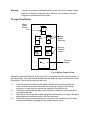
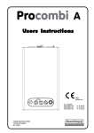
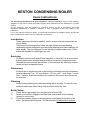
KESTON CONDENSING BOILER
Users Instructions
The Gas Safety (Installation And Use) Regulations: 1996 (as amended) impose certain statutory
obligations on gas users. Further information regarding these regulations can be obtained from your Gas
Supplier.
All gas appliances must be installed by competent persons by law in accordance with these
regulations. Membership of CORGI is indication of such a competent person with regard to gas
installation.
It is in your interests, and that of safety, to ensure that the appliance is installed correctly and that the
law is complied with. Failure to do so could lead to prosecution.
Introduction
These instructions should be carefully read to ensure safe and economical use
of your boiler.
The Keston Condensing Boiler series are high efficiency central heating
condensing boilers designed to provide central heating and indirect sanitary hot
water supply. They are designed for use with fully pumped systems only. These
boilers are supplied for natural gas use only.
Servicing
To ensure continual safe and efficient operation of the boiler it is recommended
that the appliance be checked and serviced as necessary at regular intervals.
Generally once per year will be sufficient. It is the law that any servicing must be
carried out by a competent person.
Clearances
If fixtures are to positioned close to the boiler the following minimum clearances
must be observed: Top : 127 mm, Bottom : 127 mm, Left : 1 mm, Right : 1 mm &
Front : 540 mm. Extended clearance is required to the front to allow for access
for servicing.
Cleaning
Normal casing cleaning only requires dusting with a dry cloth. To remove more
stubborn marks wipe with a damp cloth and finish with a dry cloth.
Boiler Setup
1)
2)
3)
Check that the gas supply from the gas meter is turned ON
Switch on the electric supply to the boiler and controls and set the heating
controls to call for heat.
Check the pressure gauge, to the right on the control panel on the front of the
boiler. This should show around 1 to 2 bar pressure for pressurised systems.
Warning:
If there is no pressure indicated and the system is not of the open vented
type do not attempt to light the boiler. Send for your Installer or Service
Engineer to re-pressurise the system.
To Light The Boiler
Main
On/Off
Switch
0
I
Module
On/Off
Switches
GREEN
LAMP
GREEN
LAMP
RED
LAMP
RED
LAMP
Module
Indicator
Lamps
2
1
3
Pressure
Gauge
0
Fig 1: Boiler Control Panel
Switch the main On/Off switch, to the top of the control panel on the front of the boiler, to
the ON position. Turn both module On/Off switches, below the main On/Off switch, to the
ON position. The following sequence will occur:
1)
2)
3)
4)
In the On position the Main On/Off switch will be lit with an amber light If the
switch does not illuminate check that the electricity supply to the heating
system is on and that the controls are calling for the boiler to fire.
The boiler will automatically select one of the two modules to fire and the fan in
one module will start.
After about 15 seconds the module will ignite and the green (run) lamp, the upper
lamp adjacent to the flame symbol, will also illuminate.
If the boiler detects a second module is required it will initiate firing of the other
module automatically following the same sequence as above.
The boiler is now running correctly and will proceed to switch itself on and off as the
heating reaches its operating temperature.
If the module green (run) lamp, the upper lamp adjacent to the flame symbol, goes out
and the red light illuminates for more than ten seconds, due to a failure to ignite or an
interruption to the gas supply, turn the boiler off, wait for 10 seconds and turn the boiler
on again as described above in To Light The Boiler. If the boiler still fails to ignite
after three successive attempts contact your Installer or Service Engineer.
NB: The Keston 260 and Keston 340 displays on the LED display the actual flow
temperature of the boiler. To adjust the required flow temperature hold in the push
button on the sequence controller and rotate the knob until the required temperature is
displayed. When the push button is released the display will revert to showing the actual
flow temperature.
Precautions
Care must be taken at all times to ensure that no blockage or obstruction is
present in the condensate drainage line. In addition the air intake and flue
exhaust terminals of the appliance must be free of obstruction at all times.
Gas Leak or Fault
If you suspect a gas leak turn off the appliance immediately, turn off the gas tap
to the appliance and contact your local gas region without delay.
If you suspect a fault with the appliance it must not be used until the fault has
been corrected by a competent person.
In the unlikely event of a breakdown consult your Installer or Service Engineer
END OF DOCUMENT