1
WD51/2/1997
The Keston 170 Condensing Boiler
170,000 Btu/h (50 kW) Model
Fan Powered High Efficiency
Condensing Gas Boiler
Installation And Servicing Instructions
Keston 170 - GC No 41 930 04
CE No : 87AR50
These instructions must be left either
with the user or next to the site gas
meter.
34 West Common Road
Hayes, Bromley, Kent BR2 7BX
Tel. 0181 462 0262 Fax. 0181 462 4459
WD51/2/1997
The Keston 170 Condensing Boiler
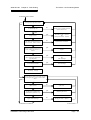
CONTENTS
Section
1
Description
1.1
1.2
1.3
1.4
1.5
GENERAL INSTRUCTION
Description
Boiler Schematic
Related Documents
Performance Data
General Data
2.1
2.2
2.3
2.4
2.5
2.6
2.7
2.8
2.9
2.10
2.11
2.12
2.13
2.14
BOILER LOCATION
Dimensions & Minimum Clearances
Service Connections
Position
Electrical
Boiler Size Selection
Gas Supply
Water Systems
Flue System
Air Supply
Compartment Installation
Condensate Drainage
Radiant Floor Heating
Low Water Volume Boiler vs. Cast Iron Boiler
Determine Radiation Needed Room-By-Room
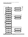
3.1
3.2
3.3
3.4
3.5
3.6
3.7
3.8
3.9
INSTALLATION OF THE BOILER
Wall Mounting Bracket
Mounting The Boiler
Assembly Practice
Installing Flue And Air Pipes
Condensate Drainage
Water System
Gas Supply
Electrical Supply
Exchanging A Boiler
4.1
4.2
4.3
4.4
4.5
4.6
4.7
COMMISSIONING OF THE BOILER
Initial Flushing
Gas Supply
Electrical Installation
LP Gas Conversion
Initial Firing
Hot Flushing
Checking The Gas Pressure
2
3
4
Page : i
WD51/2/1997
4.8
4.9
5
Timing The Gas Meter
Handing Over To The User
5.1
5.2
5.3
5.4
5.5
5.6
5.7
FAULT FINDING
Electrical Control Sequence
Fault Finding Flow Chart
Continuity Checking
Functional Flow Wiring Diagram
Electrical Wiring Diagram
Illustrated Wiring Diagram
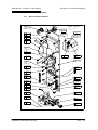
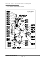
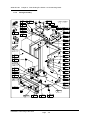
Exploded Assembly Diagrams
6.1
6.2
SERVICING
Pre Service Checks
Recommended Routine Service
7.1
7.2
7.3
7.4
7.5
7.6
7.7
7.8
7.9
7.10
7.11
7.12
7.13
7.14
7.15
REPLACEMENT OF PARTS
General
Precautions
Access
Electrical
Gas Orifice
Spark Ignition/Flame Detection Electrode
Burner Head & Burner
Heat Exchanger
Air Screen
Condensate Trap
Pressure Gauge
Sight Glass
HT Ignition Lead
Air Vent
Air Orifice
6
7
8
The Keston 170 Condensing Boiler
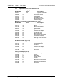
SPARE PARTS LISTINGS
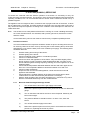
BENCHMARK INITIATIVE
As part of the industry wide “Benchmark” Initiative all Keston 170 boilers now include a Benchmark
Installation, Commissioning and Service Record Log Book. Please read this carefully and complete all
sections relevant to the appliance installation. The details of the Log Book will be required in the event
of and warranty work being required. There is also a section to be completed after each regular
service visit. The completed Log Book should be left with the customer.
CORGI CONTACT INFORMATION
The boiler should be installed and serviced only by CORGI registered operatives. All CORGI
registered Installers carry a CORGI ID cad, and have a registration number. Both should be
recorded in the Benchmark Log Book. You can call CORGI direct on 01256 372300.
Page : ii
WD51/2/1997 Chapter 1 : General Instruction
The Keston 170 Condensing Boiler
1. GENERAL INSTRUCTION
1.1
DESCRIPTION
The Keston Condensing Boiler is unique in its concept and design. While the application
for which the boiler was designed is the same as those which other boilers are used, the
Keston boiler has the added advantage of very high efficiency, and small diameter plastic
flue which can be extended to 15 metres horizontally or vertically.
The Keston uses a high power combustion blower to deliver a pre-mix of gas and air to a
downward firing burner in a high efficiency, single pass heat exchanger. Normally the
combustion temperature of the air gas mixture is around 1800oC but the Keston achieves
combustion at an amazing 1000oC thereby reducing the NOx emissions.
The flue system is room sealed and fan powered. The ignition is direct spark and fully
automatic. The boiler housing is not waterproof. The boiler should be installed in a
position where it will always be dry. A small air intake point is incorporated within the
appliance cabinet to ensure that the interior of the cabinet is maintained under a slight
negative pressure. This is a safety feature to ensure no products may leak out of the
cabinet into the installation space.
The boiler is suitable for connection to open vented or, preferably, sealed systems. The
system must be pumped central heating or pumped central heating with combined indirect
sanitary hot water. Gravity circuits must not be used.
Forming part of the boiler is the heat exchanger which is made from a highly corrosion
resistant stainless steel, formed into tightly wound coil. The hot combustion gases from
the central down firing burner pass through this coil imparting heat into the system water.
Head characteristics of the boiler coil must be taken into consideration when calculating
the pump size. The Keston boiler is not a high water content boiler and does not contain
the metal mass, or water volume, of a cast iron or steel boiler. This boiler is of low mass
and low water content and therefore responds faster when there is a call for heat. This
feature requires a higher water pumping rate through the boiler otherwise localised boiling
will occur within the boiler. Allow a pressure drop through the boiler of 13.75 ft head and a
water flow of 13.2 gallons (60 litres) per minute.
The boiler selected must be sized relative to the total calculated heat loss of the building.
The boiler rated output should not be greater than the total required to make up the
calculated heat loss plus the heat required to provide sanitary hot water, if the system is
not hot water priority design. If there are special conditions such as excessive sanitary hot
water usage consult the manufacturer.
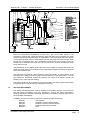
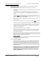
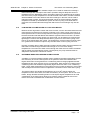
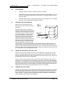
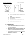
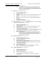
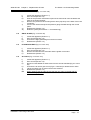
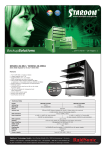
1.2
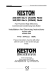
BOILER SCHEMATIC
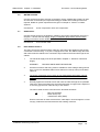
Air is drawn into the boiler through a 50mm muPVC pipe. The air flow is proved by a
differential pressure across the air control orifice. Gas is mixed with combustion air at the
inlet to the fan. The gas flow is regulated by an orifice located in the housing downstream
of the gas valve.
The gas and air are thoroughly mixed in the blower and fed into the burner located at the
top end of the heat exchanger module. The gas and air mixture is ignited by a direct spark
ignition control system and burns with a blue flame just off the surface of the burner. As
the hot products of combustion pass downwards, they are cooled by exchanging heat with
the circulating water which enters the heat exchanger coil at the bottom of the heat
exchanger.
Fig. 1.2 - Boiler Schematic
Installation & Servicing Instructions
Page : 1
WD51/2/1997 Chapter 1 : General Instruction
The Keston 170 Condensing Boiler
When the return water temperature is below 54oC, part of the water vapour in the
combustion products will condense inside the heat exchanger, thus increasing the boiler
efficiency by releasing the latent heat of condensation. This condensate falls to the bottom
of the heat exchanger where it is separated from the flue gases and exits from the boiler
through the condensate drain. Any condensate formed in the flue runs back down the
flueway and is drained at the base of the flue connection to the heat exchanger or drain
points within the flue..
The condensate is very slightly acidic (about the same acidity as vinegar) and should be
piped in a plastic pipe. It is not harmful to the waste disposal system and may be disposed
of as normal waste water.
The flue gases are piped in a 50mm muPVC pipe to the outside. The temperature of the
flue gases are usually around 10oC above the temperature of the return water. The flue
pipe should be terminated outside the building from where they cannot re-enter the
building or any other adjacent building.
The heating level may be controlled by room thermostats, hot water cylinder thermostats,
programmer time clocks and energy management systems.
1.3
RELATED DOCUMENTS
The Keston Condensing Boiler must be installed in accordance with the current issue of
the Gas Safety (Installation and Use) Regulations, current IEE Wiring Regulations,
Building Regulations, Building Standards (Scotland) Consolidation, and the Bye Laws of
the local Water Undertaking.
In addition, due account must be taken to the following Codes Of Practice:
BS 6891
:
Gas Supplies
BS 6798
:
Installation Central Heating Boilers
BS 5449
:
Installation Pumped Central Heating
BS 5546
:
Installation Domestic Hot Water
BS 5440.1
:
Flues
Installation & Servicing Instructions
Page : 2
WD51/2/1997 Chapter 1 : General Instruction
BS 5440.2
BS 5482.1
BS 7074.1
BS 7593
The Keston 170 Condensing Boiler
Air Supply
Domestic Propane & Butane Burning Installations
Expansion Vessels
Treatment of Water in Hot Water Central Heating
Systems
BS 7671
:
Requirments for Electrical Installations.IEE Wiring
Regulations 16th Edition.
For Timber Framed Buildings, British Gas Publications DM2. Also British Gas
Publications 'Guidance Notes For The Installation Of Domestic Gas Condensing
Boilers' and 'Specification For Domestic Wet Central Heating Systems'.
1.4
:
:
:
:
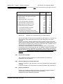
PERFORMANCE DATA
Boiler Input (gross)
kW
Btu/h
55.0
187,600
Max. Operating Flow Temp.
o
C
80.00
Max. Head (Open Systems)
m
Ft
30.50
100.0
Boiler Output To Water
(80oC Flow 60oC Return)
kW
Btu/h
49.8
170,000
Max. Press. (Sealed Sys.)
Bar
2.70
Boiler Output To Water
(60oC Flow 40oC Return)
kW
Btu/h
52.4
179,000
Min. Head (Open Systems)
m
Ft
2.5
8.0
Boiler Output To Water
(50oC Flow 30oC Return)
kW
Btu/h
54.5
186,000
Inlet Gas Pressure
mbar
in wg
20.0
8.0
Burner Setting Pressure
(Hot)
mbar
in wg
10.0
3.94
Gas Orifice Size
mm
4.5
Gas Comsumption After
10 mins Running
(CV of Gas - 38.7 MJ/m3)
(1038 Btu/Ft3)
l/s
Ft3/hr
1.42
180.73
Air Orifice Size
mm
23.0
Recommended Temperature
Differential
o
10 to 15
1.5
C
GENERAL DATA
Main Burner
Keston Premix
Flow Connection
35mm Copper
Gas Control
White Rogers 36E Series
Return Connection 35mm Copper
Combustion Fan
Keston
Type LPB 103 220/240
0.6 kW 2900 RPM
Power Supply
230V 50Hz
Pwr Consumption
610 W
Direct Spark
Ignition
RAM ElectronicsIgnition
Full Sequence Control
Ext Fuse Rating
10 Amps
Air Press. Switch
Tridelta FS6717-1428
Weight - Full
Weight - Empty
68 kg (150 lbs)
61 kg (134 lbs)
Filter
Keston Filter
Data Badge Posn
Right Hand Panel Inside
Case
Gas Supply
Connection
0.75 inch BSPT Male
(22mm to gas cock)
Water Content
7.0 litres
Installation & Servicing Instructions
Page : 3
WD51/2/1997 Chapter 2 - Boiler Connections
The Keston 170 Condensing Boiler
2. BOILER LOCATION
All dimensions in mm.
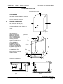
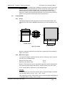
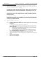
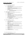
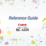
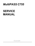
2.1
254
DIMENSIONS AND MINIMUM
CLEARANCES
The boiler must be installed in minimum
clearances shown to allow subsequent
servicing, and safe operation.
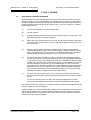
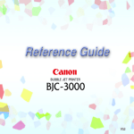
SERVICE CONNECTIONS
305
POSITION
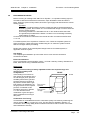
Figure 2.1.1
The Keston is not
suitable for external
installation. The boiler
may be installed in any
room or internal space,
although particular
attention is drawn to the
requirements of the
current IEE Wiring
Regulations and, in
Scotland, the electrical
provisions of the Building
Regulations applicable in
Scotland, with respect to
the installation of the
boiler in a room or
internal space containing
a bath or shower.
127
Figure 2.1.2
Dimensions
Minimum Clearances
All dimensions in mm.
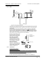
Flue
Flow
890
Air Intake
Return
Gas
Condense
50
113
7
2.3
1
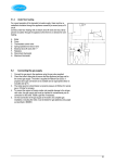
1
Gas, water, air and flue pipe,
condensation, and electrical
connections are as shown. Gas :7 0.5
inch BSP male. Flow/Return 35 mm
copper.
32
2.2
500
Where a room-sealed
appliance is installed in a
35
50
65
85
152
244
50
190
97
263
405
30
44
37
Top View
Base View
Service Connection Locations
All dimensions are in mm.
Installation & Servicing Instructions
Page : 4
WD51/2/1997 Chapter 2 - Boiler Connections
The Keston 170 Condensing Boiler
room containing a bath or shower, any electrical switch or appliance control, utilising
mains electricity, should be so situated that it cannot be touched by a person using the
bath or shower.
Compartment installation is permitted - such compartments must be constructed in
accordance with BS 6798.
The wall on which the boiler is mounted must be of suitable load bearing capacity and
must be non-combustible.
Important : It is not recommended to install the boiler on a studded wall or similar - it is
possible that the vibration from the fan would be amplified and transmitted to other parts
of the property.
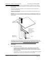
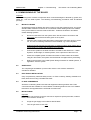
Chimneys not used for
venting any other
appliance may be used.
Secure air & flue pipes at
chimney outlet.
[NB: Refer to
Section 2.8.3]
Figure 2.3
Condensate drain
The Keston can be located virtually anywhere desired provided that all regulations are
complied with. Because of the boiler's compact size and venting flexibility, the installation
is not limited to a boiler room setting. Before locating the boiler near a living space
consider whether the sounds generated by the boiler will be objectionable.
2.4
ELECTRICAL
2.4.1
Electrical Connections
The boiler must be connected to a 230V ~ 50Hz supply, fused at 10A. All
external controls and wiring must be suitable for mains voltage. Wiring
external to the boiler must be in accordance with current I.E.E wiring regulations
and local regulations.
The method of connection to the mains electricity supply must facilitate complete
electrical isolation of the boiler, preferably by the use of a fused,
Installation & Servicing Instructions
Page : 5
WD51/2/1997 Chapter 2 - Boiler Connections
The Keston 170 Condensing Boiler
unswitched three pin plug and a shuttered socket-outlet, both complying with the
requirements of BS 1363.
The appliance must be connected to the supply via a fused double pole switch
having at least 3mm (1/8 inch) contact separation in both poles, serving only the
boiler and the system.
The connection point to the mains supply should be readily accessible and
adjacent to the boiler, except for rooms containing a bath or a shower. Refer to
section 2.3 Position.
2.4.2
2.5
External Wiring & Controls
1.
The boiler is deisgned so that all control wiring is external to the boiler.
Hence, any programmers or room thermostats etc must act by switching
the 230V supply to the boiler.
2.
System designs which allow the boiler to fire when there is no pumped
circulation must NOT be used.
3.
A programmer may be used with zone valves to give independent control
of central heating and hot water.
BOILER SIZE SELECTION
The size of the boiler to be used is determined by the total calculated heat loss of the
building. Match the calculated heat loss with the boilers rated output. If a boiler is installed
with an output rating greatly exceeding the total capacity of the distribution system the
efficiency of the boiler will be reduced.
2.6
GAS SUPPLY
A gas meter should be connected to the service pipe by the local gas region or their
contractor. An existing meter should be checked preferably by the gas region to ensure
that the meter is adequate to deal with the rate of gas supply required. Installation pipes
should be fitted in accordance with BS 6891.
Minimum/Maximum Natural Gas Pressure:
Natural gas pressure before the gas valve must be maintained at 20 mbar (8 in WG) while
the boiler is running.Gas pressures above or below this level will lead to problems
associated with the gas valve's internal pressure regulator.
Supply pipes to the boiler must not be sized less than the boiler inlet connection (22 mm).
Due consideration must be given to the supply pressure to other gas appliances in the
premises. Reduction in dynamic gas supply pressure will result in intermittent ignition
failures. Ensure gas supply pipe work is adequately sized for the length of run from the
meter to the boiler.
A gas cock is supplied loose with the boiler. This cock should be fitted in the gas line to
the boiler as close to the boiler as possible so that it is easily identified as the cock to
isolate the boiler.
2.7
WATER SYSTEMS
All piping must be installed in accordance with all applicable local and Water Supply
Bylaws for forced hot water heating systems.
Consideration must be given to pipe capabilities and pressure drop through the piping.
Installation & Servicing Instructions
Page : 6
WD51/2/1997 Chapter 2 - Boiler Connections
The Keston 170 Condensing Boiler
Water treatment must be carried out to BS 7593 : Treatment of Water in Hot Water
Central Heating Systems.
Pump isolating valves must be positioned as close to the pump as possible.
a
The Keston 170 is suitable for use on open vented water systems with combined
feed and vent.
b
It is preferable for use on sealed water systems, provided the appropriate
components required (see Section 2.7.2 Sealed Systems) are included in the
system.
c
Any system must be thoroughly flushed clean of grease, dirt and debris, prior to
connection with the boiler. A trap should be installed in the flow line to collect any
solder, or other debris, from the installation.
d
All water systems must be constructed to comply with requirements of the Local
Water Authority.
e
Only fully pumped systems can be used - gravity systems are strictly not suitable.
f
Always use a system complying with the requirements of BS 5449 and BS 6798.
g
The system must be so arranged that there shall always be a minimum flow of
13.2 gpm (60 litres/min) when the boiler is firing. This can be via a specially
installed by-pass arrangement.
h
Copper tubing to BS 2871 Part 1 is recommended.
i
Jointing should be either with capillary, threaded or compression fittings. Pipes
should have a gradient to ensure air is passed easily to vent points and water
flows readily to drain points.
j
Draining taps must be located in accessible positions which permit the draining of
the boiler and hot water storage vessel. Draining taps should be at least 22 mm in
nominal size and be in accordance with BS 2879.
k
AIR VENT POINTS
These must be fitted at all high points where air will naturally collect and must be
sited to allow complete draining of the system.
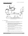
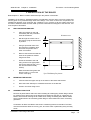
2.7.1
Open Vented Systems
A typical system is shown in Figure 2.7.1 which includes a combined feed and
vent. Note there must be no valve between the boiler flow and the open vent.
Note that the minimum static head required is 9 ft at the boiler flow pipe. If the
cold feed/vent is not brought to the flow pipe as shown, then the pressure loss
across the heat exchanger may have to be taken into account when estimating
the static pressure.
Although suitable for open vented systems with combined feed and vent
arrangements, the Keston is a low water content boiler. As such, any air
entrainement within the system water will produce boiler “kettling”. It is
therefore recommended, if in any doubt, to consider the use of sealed
systems where possible.
Installation & Servicing Instructions
Page : 7
WD51/2/1997 Chapter 2 - Boiler Connections
Expansion
Pipe
The Keston 170 Condensing Boiler
Expansion
Tank
Minimum
9ft Height
Boiler
28mm
Minimum
Keston
Cylinder
Valve
Pump
L/S
Valve
By-pass
Bal.
Valve
Strainer
Valve
Rad. 2
Rad. 1
Figure2.7.1 : Open Vented System Diagram
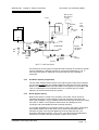
2.7.2
Sealed Systems
Sealed systems must be designed in accordance with BS 5449 and BS 7074 Pt1.
A typical sealed system is shown in Figure 2.7.2. It must include :
(i)
A safety valve fitted on the flow, adjacent to the boiler. It must be non
adjustable and preset to 3 bar. A drain pipe must be attached, at least as
big as the valve connection, and routed to drain in any area not
hazardous nor where it may be subject to freezing.
(ii)
An expansion vessel complying with BS 4814 and sized in accordance
with the requirements of BS 5449 and BS 7074 Pt 1. The vessel must be
positioned on the inlet to the pump.
(iii)
A filling point, in accordance with local water authority requirements.
(iv)
A method of system make-up (automatic or manual), in accordance with
local water authority requirements.
(v)
There must be no permanent connection of mains water to the boiler
system.
(vi)
The installation must be designed to work with flow temperatures of up to
110 oC.
Installation & Servicing Instructions
Page : 8
WD51/2/1997 Chapter 2 - Boiler Connections
The Keston 170 Condensing Boiler
Make -up vessel.
Max. capacity of
3 lt. (5pt)
Air Vent
Hose
Union
bib tap
Non-Return
Valve
Auto Air
Vent
Boiler
L/S
Keston
Strainer
Pressure
Guage
Drain
Cock
RETURN
By-pass
Bal.
Valve
HEATING CIRCUIT
FLOW
Safety
Valve
Expansion
Vessel
Hosepipe
(disconnected
after filling)
Pump
Double Check
Valve
Test Cock
BS 1010:2
Stop Tap
Hose
Connector
Figure 2.7.2 : Sealed System Diagram
All components of the system including the heat exchanger of the indirect cylinder
must be suitable for a working pressure of 3 bar and a temperature of 110 oC.
Care should be taken in making all connections that the risk of leakage is
minimised.
2.7.3
Hot Water System (if applicable)
The hot water storage vessel must be of the indirect type (certain direct cylinders
can be used provided they are suitably adapted by fitting an immersion calorifier).
DIRECT CYLINDERS MUST NOT BE USED. Further guidance is provided in BS
1394. It is advisable to fit a lockshield valve on the cylinder return to enable
balancing of the flow rate through the cylinder.
2.7.4
Boiler By-pass Piping
Boiler water flows are critical to the operation of the boiler. If flow cannot be
maintained through the system piping to meet the minimums required by the
boiler (see paragraph 2.7 (g)). Insufficient water flows through the boiler will cause
the boiler to "kettle" or even produce steam which can damage the heat
exchanger and will invalidate the heat exchanger warranty.
It is normally advisable to incorporate a boiler by-pass in the system, especially if
thermostatic radiator valves are used. The by-pass should be fitted with an
automatic by-pass valve to permit balancing of the by-pass flow rate. The
flow/return differential should be 10oC to 15oC. The valve should be adjusted to
maintain this condition with all thermostatic radiator valves closed.
Installation & Servicing Instructions
Page : 9
WD51/2/1997 Chapter 2 - Boiler Connections
2.7.5
The Keston 170 Condensing Boiler
Air Elimination
In the initial charge of water to the boiler system and in all subsequent additions
of water to the system some air will be dissolved in the water. As the water is
heated the air is driven out of the solution and will collect in high spots in the
system. These air bubbles can interfere with pumping and heat transfer and
must be eliminated.
Installation of air bleed valves at the high spot(s) in the system will allow for air
elimination when filling the system and will allow re-venting in a day or so after all
air has been driven out of solution.
Strainers
Debris in the heating
system can cause noise if
it enters the heat
exchanger. Fitting of a
Y-strainer ahead of the
circulating pump will trap
any debris left in the
system and will protect
the pump from damage.
The boiler guarantee
does not cover heat
exchanger failure due to
debris abrasion within the
system.
2.7.7
Figure 2.7.6 Strainers
Y-Strainer will
collect any loose
debris in the piping.
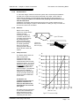
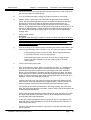
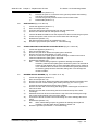
Pump Selection
The Keston boilers have low
water content heat
exchangers with a high
resistance to flow, when
compared with cast iron heat
exchanger boilers. As a result
selection of the correct pump
is essential in order to avoid
localised boiling within the
heat exchanger. The selected
pump must be capable of
maintaining the required flow
rate for the boiler against the
pressure losses contributed
by the boiler.
The Keston 170
condensing boiler offers a
hydraulic resistance of
4.2m (13.75ft) water at the
required flow rate of 60 l/m
(13.2 gpm).
If a single pump is to be used
for the entire installation the
boiler resistance must be
added to the pressure loss
caused by the rest of the
4.5
4.0
3.5
Static Pressure - m WC
2.7.6
3.0
2.5
2.0
1.5
1.0
0.5
10
20
30
40
50
60
70
Water Flow - L/min
Figure 2.7.7 : Pressure Loss Graph
Installation & Servicing Instructions
Page : 10
WD51/2/1997 Chapter 2 - Boiler Connections
The Keston 170 Condensing Boiler
system and a pump selected that is capable of meeting the flow rate required at
the total pressure loss generated by the boiler and the rest of the system. The
selected pump must comply with BS 1394. It is important to note that the
minimum flow rate must be maintained whenever the boiler is firing. Systems
using zone valves must be specifically designed to only fire the boiler when the
pump is running and the minimum flow rate can be achieved.
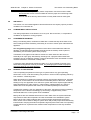
2.8
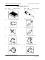
FLUE SYSTEM
2.8.1
Design
Individual air supply and flue outlet pipes are used. The material used for flue
outlet &/or air inlet must be muPVC to BS 5255 an of an internal diameter of 51
mm.
O56
40
87
80
211
O83
Flue Outlet Terminal
O56
Air Intake Terminal
Figure 2.8.1 : Terminals
Both flue outlet terminal and air inlet terminal are supplied and are illustrated in
Figure 2.8.1 above.
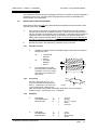
2.8.2
Maximum Lengths
The maximum lengths of both air inlet pipe and flue outlet pipe, when no bends
are used, are as detailed below.
Maximum Air Inlet Length
Maximum Flue Outlet Length
:
:
15.0 m
15.0 m
However, each bend used has an equivalent length that must be deducted from
the maximum straight length stated above. Knuckle bends must not be used.
A 92.5o sweep elbow is equivalent to 1.0m straight length.
Example:
Air inlet uses two one 92.5o sweep elbows. Hence, maximum length permissible
(ie a+b in figure 2.8.2) = 15.0m - 1.0m - 1.0m = 13.0m
Flue outlet uses one 92.5o sweep elbow. Hence, maximum length permissible (ie
c+d in figure 2.8.2) = 15.0m - 1.0 m = 14.0m
Installation & Servicing Instructions
Page : 11
WD51/2/1997 Chapter 2 - Boiler Connections
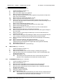
2.8.3
The Keston 170 Condensing Boiler
Slope
FLUE
c
AIR
d
b
a
Keston
Figure 2.8.2 : Flue & Air Maximum Length Example
'Horizontal' flue outlet pipework MUST slope at least 5 degrees (80 mm per metre
run) downwards towards the boiler. Pipework can be vertical. Only swept elbows
can be used.
Air inlet pipework can be truly horizontal or vertical, or sloping in a downward
direction towards the boiler but in this case rain, etc, must be prevented from
entering the pipe. There must be no troughs in any of the pipework, whether
it be air inlet or flue outlet. If a 80 mm per meter slope is not possible, contact
Keston Boilers Technical Department for further guidance.
Figure 2.8.3 :
To Terminal
Due the low temperature of the
flue gases further condensate
will form within the flue system.
Drain points, with suitable
traps, must therefore be
incorporated within the flue
system at the base of vertical
flue sections in excess of 2m.
These additional condensate
drains must be run to
discharge as detailed in
section 2.11. Such drain points
can be formed using standard
muPVC fittings. Refer to the
example in Figure 2.8.3.
Flue Condensate Drain
Point Example
To Boiler
50mm Tee Fitting
6 in min.
2.8.4
Terminations
Air inlet terminals must be
facing upwards and positioned
to ensure only fresh air is drawn into the boiler. The air terminal must be located
outside of the building. Drawing of combustion air directly from a ventilated boiler
room will invalidate the heat exchanger warranty. The air intake terminal must
face upwards to prevent entry of rain into the air intake pipework.
The flue outlet terminal is designed to face outwards but can, if desired, be
Installation & Servicing Instructions
Page : 12
WD51/2/1997 Chapter 2 - Boiler Connections
The Keston 170 Condensing Boiler
adapted to face in any direction BUT must not be directed in the region of the air
inlet.
Dimensions (mm)
Flue
Terminal
Air
Inlet
A Below openable window, air brick, etc.
300
50
B Below gutters, soil pipes, drain pipes.
75
75
C Below eaves.
300
50
D Below balconies or car port roof.
200
50
E From vertical drain or soil pipes.
75
50
F From internal or external corner.
600
50
G Above ground or balcony or roof.
300
100
H From surface facing a terminal
600
100
1,200
1,200
J From opening in a car port.
1,200
100
K Vertically from terminal on same wall.
1,500
1,500
300
300
I
From terminal facing a terminal.
L Horizontally from terminal on same wall.
Table 2.8.4
Minimum Flue Terminations & Air Inlet Dimensions
The two terminals are subject to the requirements of BS 5440 Pt 1 for clearances
from features of the building although some can be decreased to the values
indicated.
If either the air inlet or the flue outlet terminate at a height of less than 2m (6ft)
above ground level the termination must be protected by a suitable guard. The K4
terminal guard, manufactured by Tower Flue Components Ltd, is suitable for this
purpose and can be obtained from Keston Boilers.
The Keston condensing boiler, as with any condensing boiler, will generate a
condensate “plume” from the flue terminal in all weather conditions. Consideration
must therefore be given to the effect of this “plume” when selecting a location for
the flue terminal. It is advisable, for horizontal flue terminals, to place a 45O elbow
at the end of the flue to direct the condensate plume up and away from the
property,
2.8.5
Clearances From Wall
Flue outlet and air inlet terminations must be at least 60 mm and 95 mm
respectively from the wall face.
2.8.6
Distance Between Flue Outlet & Air Inlet
There is no maximum - the terminations can be on opposite sides of the dwelling
if desired.
A minimum clearance of at least 500 mm must be left between the terminations.
2.8.7
General Installations
All parts of the system must be constructed in accordance with BS 5440 Part 1,
except where specifically mentioned in these instructions.
All pipework must be adequately supported.
Installation & Servicing Instructions
Page : 13
WD51/2/1997 Chapter 2 - Boiler Connections
The Keston 170 Condensing Boiler
All joints other than push-on or plastic compression connectors must be made
and sealed with solvent cement suitable for muPVC pipes and conforming to BS
6209: 1982.
External wall faces and any internal faces of cavity walls must be made good.
2.9
AIR SUPPLY
The Keston is a room sealed appliance and therefore does not require purpose provided
ventilation for combustion air.
2.10
COMPARTMENT INSTALLATION
The casing temperature of the Keston 170 is very low. Due to this fact, no compartment
ventillation is required for cooling purposes.
2.11
CONDENSATE DRAINAGE
Being a condensing boiler, the Keston is fitted with a condensate trap at the base of the
heat exchanger and flue assembly, with facility to connect to a drain point underneath the
appliance.
Use only plastic piping and do not reduce below 15mm internal diameter within the
dwelling. Condensate should preferably be drained into the sanitary waste system or,
alternatively, the rainwater system of the property.
Termination of the pipe must be either at a branch or stack internal to the house, or
externally at an open gully. Alternatively, discharge into a purpose made condensate
soakaway can be considered. Existing or purpose built drains must use suitable corrosion
resistant material as condensate is mildly acidic.
A minimum slope downwards towards the drain of 1 in 20 is essential. Freezing of the
termination and pipework must be prevented. Any drainage pipes outside the property
must be at least 32 mm inside diameter.
2.12
RADIANT FLOOR HEATING
The low operating temperatures of this type of system lead to very good operating
efficiencies. In fact, under floor heating can produce in excess of 95% operating efficiency
from a Keston condensing boiler.
Water temperatures in radiant floor heating systems must be kept relatively low, generally
under 48oC, so that surfaces do not become uncomfortably warm to the touch. If radiant
heating is only one application for a multi-zone system which also requires higher delivery
water temperatures for other zones (i.e. water heating, skirting heaters etc.) then the
radiant floor zone temperature will need to be controlled separately from the boiler.
If radiant floor heating is the only application of the boiler, the boilers maximum operating
temperature can be lowered accordingly by introducing a supplementary control
thermostat within the control system of the installation.
Mixing valves are also available which will mix return water from the system with boiler
output water to dilute the temperature of water transmitted to the distribution system.
Mixing valves may create problems with low flow and high temperatures through the
boiler, unless care is taken to design a system which will provide proper flows and will fully
load the boiler. Keeping the boiler's temperature high will prevent the boiler from operating
at peak efficiencies. Systems which maintain boiler temperatures in this way should be
avoided.
Installation & Servicing Instructions
Page : 14
WD51/2/1997 Chapter 2 - Boiler Connections
The Keston 170 Condensing Boiler
If only a portion of the boiler's available output is to be used for radiant floor heating a
thermal storage tank will improve the boiler's operation and give adequate control of
temperature for the distribution system. By heating water to be distributed to the radiant
floor zone to the proper temperature in an indirect-fired water heater, full load conditions
will be available to the boiler because the heat exchanger in the tank can be sized to
match the boiler's output. The tank's thermostat can be set at the optimum operating
temperature needed by the distribution system and short-cycling of the boiler will be
prevented. An insulated thermal storage tank without the heat exchanger may also be
used.
2.13
LOW WATER VOLUME BOILER VS. CAST IRON BOILER
Because of their high water content and mass of metal, cast iron and steel boilers are less
responsive but somewhat more forgiving of design errors. Short-cycling of the burner on
the temperature limit control is less pronounced, though no less detrimental to operation,
because the boiler itself will absorb and radiate a significant amount of heat. Low water
volume boilers respond more quickly to a call for heat, can be made more compact and
lightweight, but must have adequate heat delivery systems to avoid short-cycling of the
burner on the temperature limit control. The heat delivery system's output must be equal
to or greater than the boiler's output to fully load the boiler or short-cycling will occur.
Likewise, pumping rates of water through low water volume boilers must be maintained so
that water is moved through the boiler fast enough so as not to reach boiling
temperatures. The slower the water moves through the boiler the more heat it will absorb
and the higher the temperatures will rise. Consequently, the pump selected must be
adequate to maintain the critical flow of water.
2.14
DETERMINE RADIATION NEEDED ROOM-BY-ROOM
A radiator or convector's ability to deliver heat is related to the water temperature and the
rate of delivery to the unit. Most systems in the past have been rated at about 80oC.
Higher efficiencies can be gained from a condensing boiler if ratings published at lower
temperatures are used. However, this is not imperative. With normal 80oC ratings used a
condensing boiler will still deliver significantly higher efficencies than a non-condensing
boiler. Lower water temperatures in the system tend to increase the efficiency of the boiler
and will help assure that the boiler is subjected to a sufficient load to avoid short-cycling.
The Keston boilers are capable of temperatures of up to 80oC but the higher the
temperature of the return water, the lower the efficiency of the system. This is true of all
boilers, though all non-condensing boiler must be kept at higher temperatures to avoid
condensation in the boiler which destroys such boilers quickly. Materials used in the
Keston are made to withstand the condensates corrosive nature.
Installation & Servicing Instructions
Page : 15
The Keston 170 Condensing Boiler
WD51/2/1997 Chapter 3 : Installation
3. INSTALLATION OF THE BOILER
Read Chapter 2 - Boiler Location and decide upon the position of the boiler.
Installation of the boiler is straightforward but consideration must be given to access to allow flue
and air pipes to be pushed through walls and ceilings. The order in which the components are
installed will depend upon particular site conditions, but in general it will be easiest and most
accurate to install the boiler and then build up the flue outlet and air inlet pipes to the terminal - this
is the sequence described.
3.1
WALL MOUNTING BRACKET
a
b
3.3
Drill through the centre hole of
the bracket, plug the hole and fix
in position.
c
Using a spirit level make sure
the bracket is completely level
and mark the position of the
other screw holes.
d
Remove the bracket and drill the
holes in the positions marked.
Plug these holes.
e
Screw the bracket to the wall
using screws of an appropriate
size for the wall type (No. 12 x 2
inch wood screws normally
suffice).
f
3.2
Place the bracket on the wall
horizontally with the pre-drilled
holes at the bottom.
Mark the bottom fixing hole and
drill for a No 8 x 1 inch wood
screw. Insert plug.
All dimensions in mm.
93
280
250
Figure 3.1 Wall Mounting Fixing Locations
MOUNTING THE BOILER
a
Lift and locate the upper rear lip on the boiler to the boiler wall bracket.
b
Move the boiler sideways to centralise the boiler on the bracket.
c
Screw in the lower fixing screw.
ASSEMBLY PRACTICE
Remove all plastic debris and burrs when installing air intake piping. Plastic filings caused
by cutting muPVC pipe must not be allowed to be drawn into the filter or combustion air
blower. Prevent dust entering the air intake when cutting on building sites. Blower failure
which is determined to be caused by plastic filings or other debris will not be covered by
guarantee.
Combustion air filters are fitted to the Keston condensing boilers as standard. This filter
must be examined at least once every year, and more often in particularly dusty and dirty
areas.
Installation & Servicing Instructions
Page : 16
WD51/2/1997 Chapter 3 : Installation
The Keston 170 Condensing Boiler
The combustion air filter will prevent plugging of the burner caused by dirt being trapped in
the burners outer mesh. The filter element supplied with the boiler is obtainable from
Keston Boilers or its distributors.
3.4
INSTALLING FLUE AND AIR PIPES
Remember the flue pipe must slope downwards back towards the boiler and this is best
achieved using 92.5o bends.
a
From the two connections on the boiler, mark the positions of the two holes for
the flue and air pipes on the wall(s) or ceiling. To allow access to drill the holes it
may be necessary to temporarily remove the boiler. If the boiler stays put then it is
imperative that the front panel and top access plate are replaced and the two
plastic pipes capped off whilst drilling. Under no circumstances must debris from
the wall or cut pipes be allowed to enter the appliance or the plastic pipework.
b
Drill the two holes in the wall/ceiling, preferably using a core drill.
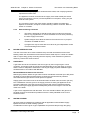
3.4.1
Diameter of holes.
i)
Allowance must be made for socketed lengths if these are to be passed
through the holes :
du
ds
ii)
3.4.2
= unsocketted
diameter
= 56 mm
= socketed
diameter
= 65 mm
T
du
D
For 'horizontal' runs of flue
pipe the holes must either be
oversized or cut at a 5o slope
(the latter may be difficult on
long holes).
L
Oversizing
For every 1m length of run, L, the
minimum diameter of the horizontal
ds
Flue Pipe
hole, D, must be du + 10 mm or ds +
10 mm respectively, assuming the
pipe touches the wall at points T otherwise D will have to be increased by
clearance from T. See Section 3.4.3 - Examples.
3.4.3
Examples
a.
Wall Depth
Unsocketted pipe
Diameter hole
L
du
D
=
=
=
=
=
750 mm
56 mm
56+{(750/1000)x10}
56+7.5
63.5 mm
b.
Wall depth
Socketed Pipe
Diameter Hole
L
ds
D
=
=
=
=
2.3 m
65 mm
65+{2.3x10}
65+23
Installation & Servicing Instructions
Page : 17
The Keston 170 Condensing Boiler
WD51/2/1997 Chapter 3 : Installation
=
c.
88 mm
Measure, cut and check the air and flue pipes to pass to the exit from the
wall(s) or ceiling.
Always thoroughly deburr all pipes and, most important, remove shavings from
within the pipe.
3.5
d.
Assemble, using adhesive, the pipework from the boiler connections to
the exit from the first wall/ceiling (remount the boiler if removed). When
pushing pipe through walls, ensure grit and dust is not allowed to enter
the pipe.
Ensure pipes are fully engaged into sockets.
Connect the condensate drainage system and fill the condensate trap by
pouring water down the boiler flue spigot ( See Section 3.5 Condensate
Drainage).
Make the final connection of flue and
Fully Engaged
air pipe to the boiler using push on, or
plastic compression couplings. Ensure
that the connectors are set vertically
otherwise leakage of condensate may
occur which will corrode the casing. Do
not use adhesive on the 'push on' end
Adhesive
of the connecting couplings.
e.
Using the same methods drill any
further holes (always covering existing
pipework), cut and assemble the
pipework.
f.
From outside, complete the two terminations - See Section 2.8 Flue
System and make good all holes.
g.
Support any pipes whose route could be displaced either of its own
accord or by accident. Any horizontal run over 1m or vertical runs of any
length must always be supported. Brackets should be placed at intervals
of approximately 1m.
h.
Check all connections for security and re-seal any joints using sovent
cement where soundness may be in doubt.
Note: It is equally important to seal the air inlet with solvent cement as
the flue outlet pipe joints.
F
A
CONDENSATE DRAINAGE
Connect the condensate drainage system to the boiler. It is advisable to use a detachable
fitting at connection to the boiler to enable easy removal for servicing.
Fill the condensate trap by pouring water into the boiler flue spigot until water is seen to
flow freely from the condensate drainage system. Make the final connection of flue pipe to
the boiler using the push on coupling supplied.
Details are provided in Chapter 2 - Section 2.11 Condensate Drainage
Connection :
22 mm plastic pipe.
Installation & Servicing Instructions
Page : 18
WD51/2/1997 Chapter 3 : Installation
3.6
The Keston 170 Condensing Boiler
WATER SYSTEM
Connect the flow and return pipework to the boiler. Ensure a detachable coupling is used
at connection to the boiler (ie compression fitting) to enable heat exchanger removal if
required. Details of system requirements are given in Chapter 2 - Section 2.7 Water
Systems.
Connections:
3.7
35 mm compression X 35 mm compression.
GAS SUPPLY
Connect the gas supply to the appliance. Details of gas supply requirements are given in
Chapter 2 - Section 2.6 Gas Supply. Supply of adequate gas pressure (with the boiler
running) is critical to ensure reliable operation of the boiler.
Connections:
3.8
0.75 inch BSP male.
ELECTRICAL SUPPLY
The entry point for the electrical supply cable is in the base of the appliance (see Section
2.2 Service Connections fig. 2.1.2) via a cordgrip bush. Feed the cable through this bush
and route inside the cabinet to the connection strip located to the front bottom right of the
cabinet.
1.
The electrical supply must be as specified in Chapter 2 - Section 2.4 Electrical
Supply.
WARNING :
THIS APPLIANCE MUST BE EARTHED.
2.
All external controls and wiring must be suitable for mains voltage. Wiring should
be in 3 core PVC insulated cable not less than 24/0.2 mm (0.75mm) to BS 6500
Table 16.
3.
The supply connection may be via a 10 amp fused double pole switch, serving
only the boiler and system controls. (Refer to Chapter 2 - Section 2.4 Electrical
Supply).
4.
Securely tighten the terminal screws and route the cable through the re-openable
cable clips. Ensure all cables are secured and that the cord grip bush is tightened
to securely grip the main cable at entry to the cabinet.
The mains cable must be connected to the terminals as follows:N
L
-
Blue wire (Neutral)
Brown wire (Live)
Yellow/Green Wire (Earth)
Ensure connection is made such that if the cable slips in its anchorage the current
carrying conductors become taut before the earthing conductor.
Installation & Servicing Instructions
Page : 19
WD51/2/1997 Chapter 3 : Installation
3.9
The Keston 170 Condensing Boiler
EXCHANGING A BOILER
Before removing an existing boiler add Fernox Supafloc , or equivalent cleaning agent, in
accordance with the manufacturers instructions. Open all radiator valves and fire the
boiler. When the system is fully heated, shut off the gas supply and drain down the central
heating system.
Important
The Keston condensing boiler contains components which could be damaged or
blocked by grease, dirt or solder etc. It is essential that sludge or scale is removed
from an existing system.
As a safety precaution it is advisable to fit an 'in line' strainer before the boiler.
The guarantee provided with the Keston 170 does not cover damage caused by
system debris or sludge.
Connect the new boiler as instructed in this manual and fit in accordance with Sections
3.1 to 3.8
For sealed systems, fill to a pressure of about 2.7 bar. Check the complete system for
water soundness. If leaks need to be rectified using flux or solder the system must be
flushed cold again before proceeding.
Reduce the pressure to the Initial System Design Pressure for sealed systems, if
applicable. Vent the system.
Gas Supply
The complete gas installation up to the boiler service cock must be checked for
soundness. BS 6891.
Electrical Installation
Carry out preliminary electrical safety checks, i.e. Earth continuity, Polarity, Resistance to
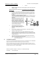
Earth, Short Circuit using a suitable test meter.
Initial Firing
The gas pressure setting is factory adjusted to within the required range and
should not normally need
GAS VALVE
re-adjustment.
If the reading is incorrect then
check
such factors as soundness of the
air and flue pipe joints, pressure
sensible joints and the gas inlet
pressure (20 mbar required). If
all joints are sound and the gas
inlet pressure is satisfactory set
Burner pressure
the gas pressure to the required
Adjustment
pressure. Full details of this
procedure are given in Section
Burner pressure
4.7. This will ensure that
test nipple.
combustion is good enough to
allow combustion fine tuning to
take place.
Combustion Fine Tuning
It is advisable on all installations that the combustion quality is checked by measuring the
carbon dioxide (CO2), or oxygen (O2), level. This procedure is detailed in Section 4.9
Combustion Fine Tuning. Badly tuned combustion will lead to reduce the life of the boiler
and invalidate the warranty.
Installation & Servicing Instructions
Page : 20
WD51/0/1997
Chapter 4 : Commissioning
The Keston 170 Condensing Boiler
4. COMMISSIONING OF THE BOILER
Important:
This condensing boiler contains components which could be damaged or blocked by grease, dirt,
solder etc., from the water system. The following commissioning procedures must be followed
precisely.
4.1
INITIAL FLUSHING
All waterways within the Keston are either copper or high alloy stainless steel. As a result
standard water treatment chemicals for conventional central heating boilers are suitable.
In any event reference must be made to BS 7593 : Treatment Of Water In Hot Water
Central Heating Systems.
a.
Disconnect the boiler from the system at the flow and return connections and
temporarily link the flow and return pipes on the system.
b.
Flush the entire system until clean water is discharged, free from dirt, flux, solder
etc. The use of a flushing chemical is recommended, e.g. Fernox Supafloc.
Sludge and scale must be removed from an existing system. Boiler failure due to
system debris or sludge shall invalidate the guarantee.
4.2
c.
Connect the system to the boiler and fill in accordance with Section 2.7 - Water
Systems. At this stage, for sealed systems, fill to a pressure of about 2.7 bar.
d.
Check the complete system for water soundness. If leaks need to be rectified
using flux and solder, the system must be flushed cold again before proceeding.
e.
Reduce the pressure to the Initial System Design Pressure for sealed systems, if
applicable. Vent the system
GAS SUPPLY
The complete gas installation up to the boiler service cock must be checked for
soundness. BS 6891.
4.3
ELECTRICAL INSTALLATION
Carry out preliminary electrical safety checks, i.e. Earth continuity, Polarity, Resistance to
Earth, Short Circuit using a suitable test meter.
4.4
LP GAS CONVERSION
All Keston condensing boilers are built and shipped as natural gas fired units. Field
conversion kits are available to convert Keston condensing boilers to use LPG. Suitable
instructions are supplied with the LPG field conversion kits.
4.5
INITIAL FIRING
Important
Checking the gas pressure to the pre-mix burner requires a special procedure, outlined
below, which must be carried out.
a.
Purge the gas supply in accordance with BS 6891.
b.
Turn the gas service cock OFF.
Installation & Servicing Instructions
Page : 21
WD51/0/1997
Chapter 4 : Commissioning
The Keston 170 Condensing Boiler
c.
Loosen the screw in the burner pressure test point (Figure 5.7.3 item 105) on the
gas valve and attach a suitable gauge.
d.
Turn on the electrical supply, setting any external controls to call for heat.
e.
ON/OFF switch - select 'ON'. The amber light will illuminate on the ON/OFF
switch, the red 'lockout' light will illuminate, the blower and pump will start and,
after about 15 seconds, a spark will attempt to light gas at the burner for
approximately 10 seconds. With the gas service cock off, the boiler will go to
lockout - red light still illuminated, but the blower and pump will continue to run. At
intervals of approximately 1 minute the boiler will make two further attempts to
fire. After the final attempt the blower will run for a further 20 seconds before
shutting down.
f.
Vent the water system.
Important:
The Keston heat exchanger consists of a single coil which can trap an air pocket.
Great care must be taken to ensure that water flow has been established through
the heat exchanger and thus ensuring no air pockets remain in the heat
exchanger and pipe work. Firing the boiler while an air pocket exists in the heat
exchanger could damage it.
g.
Note the reading on the pressure gauge caused by the suction of the blower. This
should be approximately minus 30 mbar. If it is not, check the system as follows:
If the negative pressure exceeds 30 mbar, then it suggests that there
is a possible restriction in the air inlet pipework.
If the negative pressure is less than 30 mbar, then it suggests that
there is a possible restriction in the flue outlet pipework. Note the
exact reading.
h.
Turn the gas service cock to ON.
i.
Turn off the electricity supply, wait 10 seconds and turn back on. The boiler will
again go through its ignition sequence but this time the main burner will light,
provided all air has been purged from the gas supply to the boiler. When the
burner is lit and the boiler is operating normally the green (run) lamp, the upper
lamp adjacent to the flame symbol, will also be illuminated indicating successful
ignition (If it does not and the green lamp is extinguished after 10 seconds, air is
indicated - turn off and repeat the procedure).
If ignition does not occur, the green (run) lamp, the upper lamp adjacent to the
flame symbol, will be extinguished and, at approximately 1 minute intervals, the
electronic ignition system will make two further attempts to light the burner.
If the ignition is successful and the boiler is operating normally, the green (run)
lamp, the upper lamp adjacent to the flame symbol, and the red (lockout) lamp will
be illuminated simultaneously.
If after three automatic attempts the boiler still fails to ignite, the green (run) lamp,
the upper lamp adjacent to the flame symbol, will be extinguished and the red
(lockout) lamp will remain illuminated.
If, after five manual attempts (to allow for purging of any air in the gas line), the
boiler still fails to ignite (indicated by the red (lockout) lamp) refer to Section 5.2 Fault Finding Flow Chart.
j.
Check for gas soundness between the gas service cock and connection to the
burner manifold.
Installation & Servicing Instructions
Page : 22
WD51/0/1997
4.6
4.7
Chapter 4 : Commissioning
The Keston 170 Condensing Boiler
HOT FLUSHING
a.
Allow the system to heat up, checking for water soundness.
b.
Follow instructions provided with the cleaning agent, ie Fernox Supafloc. Turn off
the boiler and flush the water system while still hot. Thoroughly flush the system
with clear water.
c.
Refill the system using a quality water treatment such as Fernox CP3. For sealed
systems, fill to the required Initial Design Pressure.
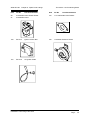
CHECKING THE GAS PRESSURE
With the boiler running measure the
burner pressure at the burner pressure
test nipple.
Fig 4.7
GAS VALVE
The gas setting is factory adjusted to
within the required range and should not
normally need re-adjustment unless the
Burner pressure
unit has also been converted to LPG as
Adjustment
part of the installation. If the reading is
incorrect then check such factors as
Burner pressure
soundness of the air and flue pipe joints
test nipple.
and the gas inlet pressure (20 mbar
required). If all joints are sound and the
gas inlet pressure is satisfactory remove
the brass dust cap covering the burner
pressure adjustment screw on the gas
valve (See fig. 4.7). Set the gas pressure to the required value as stated in table 4.7 by
turning the exposed burner pressure adjustment screw (clockwise will increase burner
pressure, anti-clockwise will decrease burner pressure).. This will ensure that combustion
is good enough to allow combustion fine tuning to take place. Replace the brass dust cap
to cover the burner pressure adjustment screw.
4.8
TIMING THE GAS METER - NATURAL GAS
After the boiler has been started, and with no other appliances using gas, time the gas
meter to be certain that the unit is running at the proper gas input. Determine the cubic
feet of gas passing through the meter and determine the input in Btu per hour. Input must
be within plus or minus 3% of the rated input.
Time, in seconds, the time taken to pass 2 cubic feet of gas through the meter (ie one
revolution of a 2 cu ft dial) or 0.1 cubic metres if the meter is of the new metric digital type.
The Keston 170, when correctly set, should take 39.8 seconds for 2 cubic feet of natural
gas and 70.3 seconds for 0.1 cubic metres of natural gas (assuming 1038 btu/h per cubic
foot). Adjust the gas valve screw clockwise to increase the input (speed up the meter) or
anticlockwise to decrease the input (slow down the meter) accordingly.
4.9
COMBUSTION FINE TUNING
Although the gas pressure is preset at the factory differing flue arrangements may require
fine tuning of the gas pressures to produce the best combustion and ensure long burner
life. It is advisable to check proper combustion by measuring gas input and the level of
carbon dioxide, or oxygen, in the flue outlet from the boiler. Overfiring or underfiring the
burner will reduce the longevity of the appliance.
Installation & Servicing Instructions
Page : 23
WD51/0/1997
Chapter 4 : Commissioning
The Keston 170 Condensing Boiler
Carbon dioxide is a colourless, odourless gas produced by all combustion processes.
When the Keston condensing boiler is operating properly carbon dioxide (CO2) levels will
be between 8.2 and 8.9% CO2 for natural gas.
To measure CO2 levels in the Keston boiler remove the 1/8" plug from the flue outlet pipe
inside the boiler (Figure 5.7.2 item 69). Insert the probe of a combustion analysis meter
and sample the gases as instructed in the test equipment's instructions.
If the CO2 levels need raising increase the gas output by turning the brass screw, under
the metal cap in the front of the gas valve, clockwise. Reduce CO2 levels by turning this
screw anti-clockwise.
If CO2 levels do not respond to adjustments the burner is probably running with too much
gas pressure. If, for instance, a clockwise adjustment to the brass screw in the gas valve
produces a decrease in CO2 the burner is too fuel-rich and not enough oxygen is present
for proper and complete combustion.
4.10
HANDING OVER TO THE USER
It is important to fully explain the following :
a.
Procedure to light and turn off the boiler, including isolation of the electrical supply
if necessary.
b.
The function of the lockout feature must be explained :
If the red light only is illuminated for more than four minutes, this means that the
boiler has failed to light. Turn off the electrical supply and wait 20 seconds. Turn
ON again and wait.
i)
If lockout recurs immediately then the gas supply should be checked as
ON, otherwise consult a Service Engineer.
ii)
If it is not possible to relight, the boiler must be isolated and a Service
Engineer called in to rectify the fault.
c.
Advise that a reduction in the water pressure reading on the gauge, for sealed
systems, indicates a leak which should be rectified before further use.
d.
Advise that the appliance should be serviced by a competent person at least once
a year.
e.
Advise on frost precautions.
f.
Hand over User Instructions.
Installation & Servicing Instructions
Page : 24
WD51/2/1997 Chapter 5 : Fault Finding
The Keston 170 Condensing Boiler
5. FAULT FINDING
5.1
ELECTRICAL CONTROL SEQUENCE
When the external controls are calling for heat, power will be fed to the boiler connection
strip at terminals L (Live) and N (Neutral). If the ON/OFF switch is also in the ON position
the boiler ON lamp (amber) will be illuminated. Provided all temperature thermostats and
pressure switches are closed, power will be fed to pins 1 & 2 on the control box, initiating
the following sequence.
(1)
The boiler lockout lamp (red) will be illuminated
(2)
The fan will start.
(3)
When the fan reaches running speed, the Air Pressure switch, normally open, will
close which will start the ignition sequence.
(4)
After a pre-purge period of about 15 seconds, the gas valve will open to allow gas
to mix with the air at the suction side of the fan and the ignition spark will occur at
the main burner.
(5)
When the burner ignites, the flame is detected by the control box through the
combined flame sensor/ignitor and the ignition spark is stopped. Both the lockout
lamp (red) and the boiler run lamp (green), the upper lamp adjacent to the flame
symbol, will be illuminated. The boiler is now in its normal run condition.
(6)
The burner will continue to operate until the gas valve interrupts the gas supply.
The gas valve will be closed by the control box if power is interrupted to the boiler
by any external control or the boiler thermostat. If an interruption to the gas supply
causes loss of the flame, the control box will pause for approximately 10 seconds
and then attempt to re-ignite the unit. If this attempt fails, i.e. due to continued
lack of gas supply, the boiler will make two further attempts to ignite at intervals of
approximately 1 minute and will then go to a lockout state (red lamp illuminated
only). Once the gas supply has been resumed the boiler can be reset by turning
the boiler off and then on again on the boiler control panel.
(7)
The boiler can also be shut down by any of the flow limit, flow overheat and the
flue overheat thermostats, gas low pressure switch and by the low water pressure
switch.
In such an event the green (run) lamp, the upper lamp adjacent to the flame
symbol, will be extinguished and only the red (lockout) lamp will be illuminated.
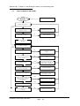
Any failure of the boiler to sequence in the above manner should be investigated using the
following trouble shooting flow diagram.
Before attempting any electrical fault finding, always carry out preliminary electrical system
checks. On completion of any service/fault finding task which has required the breaking
and remaking of electrical connections, the checks, earth continuity, polarity, short circuit,
resistance to earth must be repeated.
Installation & Servicing Instructions
Page : 25
WD51/2/1997 Chapter 5 : Fault FindingThe Keston 170 Condensing Boiler
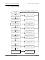
5.2
FAULT FINDING FLOW CHART
START
Apply Power To Boiler.
Is amber switch light on?
yes
no
Is there 230V between
terminals SL & N?
no
Check External Controls.
yes
no
Is the boiler switched on?
Switch On Boiler.
yes
Faulty Switch Neon
-Replace.
Is the f an running?
yes
no
no
Is the boiler thermostat closed?
Boiler return is too hot. Allow
to cool. OR faulty thermostat Replce.
yes
Is there 230V between control
box pins 10 & 2 and between
pins 10 and 1?
no
Check continuity (see section
5.3)
yes
Is the air pressure switch stuck
in the NO position?
yes
Faulty pipe connections to Air
Press. Switch. OR Faulty Air
Press. Switch - Replace.
no
Is there 230V between control
box pins 6 & neutral?
no
Control box faulty.
yes
no
Is the motor relay operating?
Relay not secure in socket or
relay faulty - replace
yes
Is there continuity between live
supply from relay to blower &
Neutral through motor
resistance?
no
yes
Motor/Fan fault y - Replace.
yes
Wait for motor to cool.
Is motor overload tripped?
no
Is there wiring continuity
& in-line connector
to motor?
no
Identify & correct break.
Continued on sheet 2
Installation & Servicing Instructions
Page : 26
WD51/2/1997 Chapter 5 : Fault Finding
The Keston 170 Condensing Boiler
Continued from sheet 1
Does ignition sequence start?
yes
no
no
Is lockout light on?
Switc h off & if problem persists
replace control box.
yes
Has the Air Press. Switc h
changed over?
yes
Blocked air filter - replace
OR
Faulty control box - replace
no
Are tubes and connections to
the Air Press. Switch sound?
no
Correct tube connection
yes
Is the air press. across the Air
Press. Switch more than 4 in
water?
yes
Faulty pressure switch replace
no
Is the air filter dirty or the air
inlet, exhaust or condensate
pipe blocked?
yes
Replace air filter
OR
clear blockage
no
yes
Is the Burner blocked
Clear blockage
no
Fan faulty - change
Is the gas flow rate to the boiler correct
for the gas type in use (ie LPG or Nat.
Gas )?
yes
no
Is gas supply pressure at gas
valve correct?
no
Check gas supply or turn on
gas cock.
yes
Is gas burner pres sure per
specification (Section 4.7)?
yes
Replace gas orifice.
no
no
Is gas valve opening?
Faulty gas valve - replace.
yes
Continued on sheet 3
Installation & Servicing Instructions
From sheet 3
Page : 27
WD51/2/1997 Chapter 5 : Fault FindingThe Keston 170 Condensing Boiler
Continue d fro m Sheet 2
Contin ued o n sh eet 2
ye s
Is there 230V at val ve
Faulty Gas V alve - Replace.
no
Is there 230V at Gas Low
Press. Sw itch
ye s
Faulty Gas Low P ressure
Switc h - Repl ac e
no
Faulty C ontrol B ox - Replace.
Is there a spark present?
yes
no
Is the H T v ol tage present at
top of igni tion electr ode?
no
Faulty C onrtrol B ox - R eplace.
ye s
no
Is the s park gap 4 m m?
Replace/Adjust S park Plug.
ye s
Electrode Fault y - R eplace.
Does the burner ignite?
yes
no
Recheck gas output pressure.
Check HT lead is securely
fixed. Clean or replac e burner.
Does flam e stop after 5 - 10
seconds ?
ye s
no
Is boiler earthed correc tly?
Earth Boiler.
ye s
Are live and neutral supply
lines crossed at terminals L &
N?
yes
Correct W iring.
no
Faulty C ontrol B ox - Replace.
Installation & Servicing Instructions
Page : 28
WD51/2/1997 Chapter 5 : Fault Finding
5.3
The Keston 170 Condensing Boiler
CONTINUITY CHECKING
T o c h e c k c o n t in u it y c o n ne c t o n e pro b e t o a n e u tr a l
an d us e th e o th e r pro b e to c he c k f o r 23 0 V .
ST A R T
no
Is th er e 2 3 0 V a t te r m in a l L ?
C h e c k e x te r na l c o n tro ls .
ye s
Is th er e 2 3 0 V a t th e O N / O F F
s w itc h ( b o t h te rm in a ls )?
no
F a u lty s w itc h - R e p la c e .
ye s
I s th er e 2 3 0 V a t th e b o ile r
the r m o s ta t ( b oth t e r m in a ls ) ?
no
B o ile r is u p to t e m p e ra tu r e .
A llo w to c o ol O R p u m p n o t
ru n n in g O R fa u lt y th er m o s ta t R e p la c e
ye s
Is t h er e 2 3 0 V a t th e f lo w
ov er h e a t th e r m o s ta t ( b o th
ter m in a ls ) ?
no
T h e r m os t a t t ri pp e d - r e s e t O R
fau l t y th e rm o s ta t - R e p la c e .
ye s
Is th er e 2 3 0 V a t th e th e r m al
f us e l in k ( b o th ter m in a ls ) ?
no
H ig h c a b in e t te m pe r a tu r e c h ec k a ll jo in t s for p r o d u c ts
le a k a g e - R e p l ac e th e r m a l f u s e
ye s
Is th er e 2 3 0 V a t th e f lo w hi g h
lim it t h e r m o s t a t ( b o th
ter m in a ls ) ?
no
H ig h w a te r t e m p e r a tu r e O R
fau l t y th e rm o s ta t - R e p la c e .
ye s
I s th er e 2 3 0 V a t th e w a te r
pr e s s . s w itc h ( b o th te rm in a ls ) ?
no
C h e c k w a te r le v e l h e a d e r
tan k / s y s t e m pr e s s u r e O R fa u lty
s w it c h - R e p la c e
ye s
Is th er e 2 3 0 V a t t h e flu e
pr o te c tio n th e r m o s ta t (b o th
ter m in a ls ) ?
no
T h e r m os t a t t ri pp e d - r e s e t O R
fau l t y th e rm o s ta t - R e p la c e .
ye s
Is t h er e 2 3 0 V a t th e g a s lo w
pr e s s . s w itc h ( b o th ter m in a ls ) ?
Installation & Servicing Instructions
no
C h e c k g a s s u p p ly t o b o ile r O R
f au l ty s w itc h - R e p la c e .
Page : 29
WD51/2/1997 Chapter 5 : Fault FindingThe Keston 170 Condensing Boiler
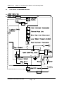
5.4
FUNCTIONAL FLOW WIRING DIAGRAM
PL
SL
EMC Filter
2
1
5
4
10
8
6
Pump L
Pump N
N
EMC Filter
Installation & Servicing Instructions
Page : 30
WD51/2/1997 Chapter 5 : Fault Finding
5.5
The Keston 170 Condensing Boiler
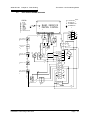
ELECTRICAL WIRING DIAGRAM
APS-AIR PRESSURE SWITCH
LEGEND
L -INCOMING LIVE
B -BLUE
BK -BLACK
OR -ORANGE
R -RED
PK -PINK
W -WHITE
G -GREEN
BR -BROWN
V -VIOLET
Y/G-GREEN-YELLOW
N -INCOMING NEUTRAL
RAM-2EMC22
IGNITION CONTROL
HV
-INCOMING EARTH
PUMP
14
N
13
no
nc
93OR
m
2 1
3
7 6
4
8
RELAY
12B
91OR
WATER PRESSURE
SWITCH
L
93R
APS
p
15
14B
6BR
GAS LOW
PRESSURE
SWITCH
54G
FLUE OVERHEAT
THERMOSTAT
95G
15BR
1BR
10BK
55BR
92OR
G/Y
13 12 11 10 9 8 7 6 5 4 3 2 1
53W
GAS
VALVE
RED
LAMP
90R
GREEN
LAMP
56R
FLOW HIGH LIMIT
THERMOSTAT
59PK
52BK
THERMAL FUSE
12V
12
11W
11
10BK
10
9G
9
8W
8
7W
7
6B
6
6B
5BR
5
5BR
4B
FLOW OVERHEAT
THERMOSTAT
12V
3BR
BLOWER
W
4
N
3
SL
51PK
2
1BR
1
PL
5R
BOILER
THERMOSTAT
ON/OFF
SWITCH
EMC
FILTER
BR
Installation & Servicing Instructions
Page : 31
WD51/2/1997 Chapter 5 : Fault FindingThe Keston 170 Condensing Boiler
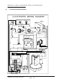
ILLUSTRATED WIRING DIAGRAM
ILLUSTRATED WIRING DIAGRAM
7W
51PK
Thermal Fuse
RAM
Control
56R
52BK
53W
Flow High
Limit Stat
G/Y
9
10
92OR
93OR
Low Water Pressure Switch Gas Low
Pressure Switch
95G
G/Y
G/Y
91OR
54G
Air Pressure Switch
Flue Overheat Stat
11W
8W
8W
12B
BR
PL
(room
stat )
91OR
G/Y
6BR
5BR
4B
9G
3BR ON/OFF
SWITCH
FILTER
Lockout
Lamp
Run
Lamp
90R
W
B
12V
8W
7W
6B
10
9
8
7
6
5
4
3
2
1
Relay
BR
5R
12
11
B
10BK
59PK
15
14
13
N
SL
6BR
PUMP
L
N
8
10BK
55BR
Gas Valve
Ignition Electrode
1
2
3
4
5
6
7
Blower
Installation & Servicing Instructions
Page : 32
93R
Flow Overheat Stat
Boiler Stat
5R
5.6
WD51/2/1997 Chapter 5 : Fault Finding
5.7
The Keston 170 Condensing Boiler
Exploded Assembly Diagrams
5.7.1
Boiler Controls Asembly
154 SCREW
04.1.00.78.0
BOILER CONTROLS
158
TR2 THERMOSTAT
17.4.11.00.0
OPTIONAL
106 IGNITION CONTROL
1
PACTROL 04.4.01.00.0
RAM 04.4.01.00.1
156
K170 - 17.4.00.00.0
FUSE ISOLATOR
145 04.4.20.00.0
SECTION 1
SOCKET
112 FUSE
04.4.19.00.0
SCREW
04.1.00.84.0
122 IGNITION CABLE
PACTROL 04.4.11.00.0
RAM 04.4.11.00.1
SOCKET
124 RELAY
17.4.04.00.0
RELAY
123 17.4.03.00.0
FUSE
107 THERMAL
04.4.18.00.0
RELAY CLAMP
105 17.4.00.02.0
SCREW
108 04.4.00.06.0
8
SCREW
SECTION 1
125 17.4.00.01.0
PRESSURE
109 AIRSWITCH
TERMINAL BLOCK
148 13.4.00.10.0
BLUE/WH. 04.4.04.00.1
13
162
SCREW
04.1.00.40.0
117
HARNESS
PACTROL 17.4.10.00.0
RAM 13.4.10.00.2
MAINS
FILTER
144 SUPRESSOR
04.4.02.00.0
13 SECTION
BLOCK
111 TERMINAL
04.4.05.00.0
TERMINAL BLOCK
LABEL
13.4.00.03.1
110 BASE
13
1
162 SCREW
04.4.00.10.0
SEALING GASKET
121 04.4.00.04.0
3
BULB
119 NEON
04.4.12.00.0
SECTION 1
SWITCH
113 ON/OFF
04.4.06.00.0
LAMP
115 RED
04.4.08.00.0
Installation & Servicing Instructions
GAUGE
116 04.4.09.00.0
O
I
bar
LAMP
114 GREEN
04.4.07.00.0
Page : 33
WD51/2/1997 Chapter 5 : Fault FindingThe Keston 170 Condensing Boiler
5.7.2
Waterway, Condensate & Flue Assembly
51 SCREW
04.1.00.80.1
WATER WAY, CONDENSATE
& FLUE ASSEMBLY
K170 - 17.2.00.00.0
50 IGNITER
04.2.13.00.1
GASKET
49 IGNITER
04.2.00.28.2
55 GASKET
17.2.00.05.2
56 SCREW
04.1.00.79.1
TEST FITT.
53 PRESS.
04.2.28.00.0
52
SCREW
04.2.00.29.1
47 MANIFOLD
17.2.00.27.2
82 SECTION 3
EXHAUST PIPE
65 17.2.06.00.0
COMBUSTION
PLUG
69 TEST
04.2.00.49.1
GLASS
48 SIGHT
04.2.12.00.1
46 GASKET
17.2.00.01.2
FLUE OVERHEAT
67 THERMOSTAT
04.2.19.00.0
45 BURNER
17.2.04.00.0
44
35 WATER FLOW
PIPE
70 17.2.00.22.0
81 SCREW
04.1.00.41.3
SHEATH
160 IMIT
17.2.00.57.0
WATER OUT
HIGH VOLTAGE
LABEL
04.2.00.58.0
MANIFOLD
54 17.2.00.24.1
HEAT EXCHANGER
FLOW HIGH LIMIT
43 INSULATION
17.2.03.00.1
72 THERMOSTAT
04.2.22.00.0
HEAT EXCHANGER
14
42 17.2.01.00.2
WATER RETURN
MANIFOLD
61 17.2.00.23.0
WATER FLOW OUT
71 THERMOSTAT
04.2.21.00.0
75 GASKET
04.2.00.54.0
60
154 SCREW
04.1.00.78.0
DRAIN VALVE
04.2.16.00.0
TRAP
58 CONDENSATE
04.2.14.00.1
WATER RETURN
63 THERMOSTAT
04.2.17.00.0
HOSE
68 CONDENSATE
04.2.00.59.0
CLAMP
64 HOSE
04.2.00.57.0
59
WATER PRESSURE
SWITCH
73 04.2.23.00.0
14 SCREW
04.1.00.41.0
35 WATER RETURN
PIPE
17.2.00.06.0
CONDENSATE
HOSE
57 TRAP
04.2.00.58.0
RING
74 SEEGER
04.2.00.53.0
Installation & Servicing Instructions
Page : 34
WD51/2/1997 Chapter 5 : Fault Finding
5.7.3
The Keston 170 Condensing Boiler
Air - Gas Assembly
TEST FITT.
53 PRESS.
04.2.28.00.0
94
SCREW
04.3.00.28.0
AIR-GAS ASSEMBLY
K170 - 17.3.00.00.0
100
GAS TEE
04.3.00.34.1
LOW GAS
SWITCH
101PRESSURE
04.3.09.00.0
90
GAS VALVE
91 REGULATOR
04.3.07.00.0
SOLENOID
149 MAIN
04.3.07.01.0
92
AIR HOSE CLAMP
17.3.00.07.0
85
AIR INLET
FLEX. CONNECTOR
17.3.00.02.0
BLOCK
150 CONNECTOR
04.3.07.02.0
GAS INLET
TUBE
93 FLEXIBLE
17.3.07.00.5
ADJ. SCREW
103 AIR
17.3.10.00.0
ORIFFICE SCREW
84 AIR04.3.00.40.0
AIR ORIFICE
SOLENOID
157 SECONDARY
04.3.07.03.0
131 17.3.00.01.0-NG
17.3.00.01.1-LPG
90 GASKET
17.3.00.06.0
53
88
INLET GASKET
95 GAS
17.3.00.08.0
GASKET
17.3.00.04.1
AIR/GAS
96 NUT
17.3.00.09.0
GAS ORIFICE
PRESS. TUBE
98 HIGH
04.3.00.32.0
MANIFOLD PLUG
89 17.3.00.05.1
AIR/GAS
87 17.3.00.03.0-NG
17.3.00.03.1-LPG
FLEXIBLE TUBE
82 17.3.05.00.1
104
PRESS. TUBE
97 LOW
04.3.00.31.0
155 SCREW
04.1.00.81.0
52 SCREW
04.2.00.29.0
GASKET
102 SEALING
04.1.00.38.0
AIR/GAS
83MANIFOLD
17.3.06.00.0
VALVE SCREW
86 GAS
04.3.00.16.0
104 GASKET
17.2.00.05.0
79 CAPACITOR
17.3.02.00.0
78 BLOWER
17.3.01.00.0
BLOWER
ISOLATOR
80 RUBBER
04.3.04.00.0
1
SECTION 1
17 SCREW
04.1.00.76.0
Installation & Servicing Instructions
Page : 35
WD51/2/1997 Chapter 5 : Fault FindingThe Keston 170 Condensing Boiler
5.7.4
Casing Assembly
13 SCREW
04.1.00.40.0
14 SCREW
04.1.00.41.0
6
BURNER ACCESS COVER
17.1.00.01.0
CASING ASSEMBLY
K170 - 17.1.00.00.0
VALVE
38 GAS
17.1.13.00.0
21
35mm GROMMET
17.1.00.05.0
26
FLOW LABEL
04.1.00.53.1
20
56mm GROMMET
17.1.00.04.0
FLUE LABEL
25 EXHAUST
04.1.00.52.0
2
TOP COVER
17.1.04.00.0
LABEL
28 WARNING
04.1.00.55.0
39
INLET LABEL
24 AIR
04.1.00.51.0
PR. ADAPT.
36 NEG.
04.1.00.62.0
EXHAUST TERMINAL
17.1.16.00.0
17 SCREW
04.1.00.76.0
CLAMP
40 HINDER
17.1.00.03.2
FILTER
19 AIR
17.1.12.00.0
9
BRACKET
04.1.00.35.0
5
AIR FILTER COVER
17.1.07.00.0
CLAMP
41 SHUTTING
17.1.09.00.0
37 SILENCER
17.1.11.00.1
HOLDERS
34 CABLE
04.1.00.61.0
4
FRONT DOOR
17.1.06.00.0
PLATE
23 NAME
17.1.00.06.1
ILLUSTRATED
DIAGRAM
29 WIRING
13.1.00.07.1
16 WASHER
04.1.00.43.0
HEAT EXCHANGER
FIXING ROD
17.1.00.02.1
LOCKWASHER
18 EARTHING
04.1.00.45.0
7
LABEL
27 RETURN
04.1.00.54.1
11
15
15
NUT
04.1.00.42.0
8
CONTROLS PLATE
17.1.00.18.3
16
SPRING CLAMP
17.1.00.30.0
153 SCREW
04.1.00.77.0
POINT LABEL
31 TEST
04.1.00.58.0
LABEL
33 FLAME
04.1.00.60.0
14
1
OUTER SHELL
17.1.03.00.0
INLET LABEL
32 GAS
04.1.00.59.0
3
DEVICE BOX
17.1.00.19.0
GROMMET
22 22mm
04.1.00.49.0
KES
TON
PLUG
66 PLASTIC
04.1.00.75.0
62
10 SWITCH
17.1.00.29.1
LABEL
30 KESTON
17.1.00.72.0
ELECTRIC MAIN
NUT
62 FIXING
17.1.00.32.0
RETAINER
35 WIRE
04.1.16.00.0
Installation & Servicing Instructions
Page : 36
WD51/2/1997 Chapter 5 : Fault Finding
5.7.5
The Keston 170 Condensing Boiler
Exploded Diagrams Parts Reference List
Boiler Controls Assembly (Fig. 5.7.1)
GC Number
Code
E01 074
106
170 084
109
114 076
111
114 077
113
114 078
114
114 079
115
114 080
116
Description
Ignition Control Box
Air Pressure Switch
Electrical Terminal Block
On/Off Switch
Green (Run) Lamp
Red (Lockout) Lamp
Pressure Gauge
Waterway, Condensate & Flue Assembly (Fig. 5.7.2)
GC Number
Code
Description
114 115
42
Heat Exchanger
114 117
45
Burner
114 118
46
Burner Head Gasket
114 028
48
Sight Glass
375 527
49
Ignitor Gasket
114 120
50
Spark Ignition Electrode
114 029
53
Pressure Test Nipple
114 032
58
Condensate Trap
375 530
63
Boiler Thermostat
375 532
67
Flue Overheat Thermostat
114 043
69
Combustion Test Plug
375 533
71
Flow Overheat Thermostat
375 534
72
Flow High Limit Thermostat
114 045
73
Water Pressure Switch
Air - Gas Assembly (Fig. 5.7.3)
GC Number
Code
114 131
78
114 146
131
375 536
91
114 029
53
114 073
101
114 136
87
Description
Combustion Blower
Air Orifice
Gas Valve
Pressure Test Nipple
Low Gas Pressure Switch
Gas Injector
Casing Assembly (Fig. 5.7.4)
GC Number
Code
114 095
1
114 108
23
114 099
5
114 105
19
114 096
2
114 100
6
114 109
29
114 098
4
Description
Cabinet
Data Badge
Air Filter Cover
Air Filter
Cabinet Top Cover
Burner Access Cover Plate
Illustrated Wiring Diagram
Front Door
Installation & Servicing Instructions
Page : 37
WD51/2/1997 Chapter 6 : Servicing
The Keston 170 Condensing Boiler
6. ROUTINE (ANNUAL) SERVICING
To ensure the continued safe and efficient operation of the boiler it is necessary to carry out
routine servicing at regular intervals. The frequency of the servicing will depend upon the particular
operating conditions, but it is recommended that an annual service should be carried out by a
qualified engineer.
The appliance has an integral air filter, mounted at the top right hand side of the boiler, to which
the air intake pipe is connected. This filter should be examined every time the boiler is serviced. It
may need more frequent inspection according to the condition of the atmosphere in which the air
intake terminates.
Note:
The air filter can be easily blocked if the boiler is running on or near a building site having
an excess of airborne dust. It is essential, with a premix gas burner, that the air is clean
and free of dust.
It is the law that any service work must be carried out by competent qualified persons.
6.1
Pre-Service Checks
It is recommended that an inspection should be carried out prior to shutting down the unit
for servicing. Remove the front cover by removing the screws retaining the top of the door
and lifting the cover from the base (Front cover located by two pegs). The following items
should be observed:
a.
b.
c.
d.
e.
f.
g.
h.
i.
j.
6.1.1
Smooth starting and running of the blower.
Smooth lighting of the burner.
Check for leakage of gas, gas/air or combustion products.
Check for condensate leaks.
Check the colour and appearance of the flame. A sky blue flame slightly off the
burner gauze is normal. The burner itself should appear dark. Any glow on the
burner indicates gauze blockage requiring cleaning, an incorrect gas flow or an air
intake blockage.
Check that the temperature differential between the flow and return pipes is less
than 15oC. The temperature difference should be between 10oC and 15oC.
Check for water soundness.
Inspect the flue vent and air intake pipework. Joints must be sound and all
pipework well bracketed.
Check that there is a steady fall back to the boiler from the flue pipe to allow
condensate to run back into the boiler (See Section 2.8.3 Slope).
With the boiler operating at a low return temperature (i.e. less than 50oC) check
that the condensate flows freely from the condensate line.
Burner & Heat Exchanger Blockage Checks
i)
Turn off the boiler & shut off the gas supply to the boiler.
ii)
Remove the pressure point screws from points A & B. Attach a differential
gauge.
iii)
Turn on the boiler and wait for the fan to reach full speed. Obviously the
burner will not light.
iv)
The pressure difference should be below 14 mbar. If not, clean the
burner.
v)
Turn off the electrical supply to the boiler.
vi)
Remove the pressure point screw from point C and transfer the tube from
point A to C, replacing the screw on point A.
Installation & Servicing Instructions
Page : 38
WD51/2/1997 Chapter 6 : Servicing
The Keston 170 Condensing Boilers
Flue
Pressure Test
Point A
Pressure Test
Point B
Heat
Exchanger
Shell
Flue Overheat
Thermostat
Combustion
Test Point
&
Pressure Test
Point C
Burner Heat (From Above)
Fig 6.1.1 Pressure Test Point Locations
6.2
vii)
Turn on the electrical supply to the boiler (gas still off), wait for the fan to
reach full speed.
viii)
The pressure difference should be below 17 mbar. If not, clean heat
exchanger.
ix)
Disconnect the gauge from point B. Refit the screw.
x)
Read pressure of point C.
xi)
The maximum pressure should be 3.5 mbar. If the pressure is greater
than this, check the flue for blockage.
xii)
Turn off the electrical supply to the boiler.
xiii)
Remove the pressure gauge tube and refit the screw.
xiv)
Open the gas service cock.
Recommended Routine Service
a.
Inspect the air filter located at the top right hand side of the boiler. Release the
toggle catch on the filter tray and remove the filter.
If the filter looks dirty remove the dirt with a vacuum cleaner or by other means. If
in any doubt renew the filter element.
b.
Remove the burner head (Section 7.7) and inspect the burner appearance. Black
markings or other discolourations on the gauze indicate too much gas or a lack of
air possibly due to a blocked air filter. Any breakages or damage to the burner
mesh indicate the burner must be replaced.
c.
If necessary, either due to discolouration or a high pressure differential between
points A & B in the pre-service checks, clean the burner with a mild household
detergent and rinse under a hot running tap.
Installation & Servicing Instructions
Page : 39
WD51/2/1997 Chapter 6 : Servicing
The Keston 170 Condensing Boiler
d.
If necessary, either from visual inspection or a high pressure differential between
points B & C in the pre-service checks, clean the heat exchanger using a suitable
stiff plastic bristle brush, vacuum out any large particles and flush the heat
exchanger with fresh water until the water flowing from the condensate drain is
clear. When brushing the heat exchanger take care not to damage the
condensing plug in the lower half of the heat exchanger.
e.
Remove the condensate trap (Section 7.10) and clean by flushing through with
clean running water.
f.
Check the electrode mounted on the burner head. If the point is damaged or
burnt replace it.
Check that the spark gap measures 4 mm.
g.
Replace the burner head, renewing the gasket if necessary, and reconnect the
gas/air supply and the ignition lead. Ensure the flanged gas/air supply joint is air
tight.
h.
Turn on the electrical supply to the boiler and allow the boiler to reach operating
temperature levels.
i.
Visually inspect the burner through the glass spy hole at the burner head (a small
mirror will prove useful).
j.
Recheck the burner pressure by following the procedure detailed in Section 4.7
k.
Remove the combustion test point plug from the flue pipe. This is situated around
150mm (6ins) from the bottom of the flue elbow at its connection to the heat
exchanger.
l.
Using an approved combustion tester sample the flue products via the
combustion test point. CO2 levels of between 8.2% and 8.9%, for natural gas,
should be observed. If such levels are not observed tune the combustion as
described in Chapter 4 - Commissioning. Also check the gas flow as detailed in
Sections 4.8 and 4.9
m.
Replace the combustion test point plug.
n.
Check all joints for soundness up to the gas burner.
Installation & Servicing Instructions
Page : 40
WD51/2/1997 Chapter 7 : Replacement Of Parts
The Keston 170 Condensing Boilers
7. REPLACEMENT OF PARTS
INDEX
7.0
GENERAL
7.1
PRECAUTIONS
7.2
ACCESS
7.3
PROCEDURES - GENERAL
7.4
ELECTRICAL
7.4.1
ON/OFF SWITCH
7.4.2
BOILER THERMOSTAT
7.4.3
NEONS
7.4.4
FLOW OVERHEAT, FLOW HIGH LIMIT & FLUE PROTECTION
THERMOMSTATS
7.4.5
WATER PRESSURE SWITCH
7.4.6
IGNITION CONTROL BOX
7.4.7
AIR PRESSURE SWITCH
7.4.8
COMBUSTION BLOWER
7.4.9
GAS CONTROL VALVE
7.4.10 GAS LOW PRESSURE SWITCH
7.5
GAS ORIFICE
7.6
SPARK IGNITION/FLAME DETECTION ELECTRODE
7.7
BURNER HEAD & BURNER
7.8
HEAT EXCHANGER
7.9
AIR FILTER
7.10
CONDENSATE TRAP
7.11
PRESSURE GAUGE
7.12
SIGHT GLASS
7.13
HT IGNITION LEAD
7.14
AIR ORIFICE
Installation & Servicing Instructions
Page : 41
WD51/2/1997 Chapter 7 : Replacement Of Parts
7.0
The Keston 170 Condensing Boilers
GENERAL
The following must always be carried out by a competent/qualified person.
7.1
7.2
7.3
7.4
PRECAUTIONS
i)
Always switch off the mains electricity supply and disconnect the plug at the
isolating switch and socket. (If a switch only is used then remove the fuse.)
ii)
Gain access to the appliance (Section 7.2) and turn off the gas supply at the
appliance service cock.
ACCESS
i)
Remove the front door by removing the three screws to the front of the top panel.
The front panel may then be removed by tilting forward and lifting vertically to
disengage the two locating studs in the base of the front panel.
ii)
Access to the burner head can be gained by removing the access plate in the top
panel of the appliance.
iii)
Access to the rear of the control panel and base of the unit can be gained by
removing the control panel at the bottom of the boiler. Remove the two screws to
the control panel then gently pull the control panel free of the boiler casing. This is
secured by three press studs on either side and a central press stud at the bottom
of the control panel.
REPLACEMENT PROCEDURES
i)
Always replace in the reverse order unless otherwise stated.
ii)
Electrical connections must be remade in accordance with the Wiring Diagram
(Section 5.5).
iii)
Test the soundness of any gas carrying or water carrying joint broken during the
service procedures.
ELECTRICAL COMPONENTS
7.4.1
On/Off Switch (Fig. 5.7.1 item 113)
i)
i)
iii)
iv)
v)
v)
7.4.2
Isolate the appliance (Section 7.1)
Gain access (Section 7.2)
Remove the push on connectors from the switch taking note of the
correct positions.
Press in the catches and push the switch forwards through the control
panel.
Reassemble (Section 7.3)
Check for correct operation of the switch.
Boiler Thermostat (Fig. 5.7.2 item 63)
i)
ii)
iii)
iv)
Isolate the appliance (Section 7.1)
Gain access (Section 7.2)
Remove the push on connectors from the thermostat taking note of the
correct positions.
Unscrew the two retaining screws and remove the thermostat.
Installation & Servicing Instructions
Page : 42
WD51/2/1997 Chapter 7 : Replacement Of Parts
v)
7.4.3
iv)
v)
vi)
vii)
iv)
v)
vi)
Isolate the appliance (Section 7.1)
Gain access (Section 7.2)
Remove the push on connectors from the thermostat taking note of the
correct positions.
Unscrew the two retaining screws and remove the thermostat.
Flue protection thermostat only
The thermostat seal is maintained via a small 'O' ring between thermostat
and flue pipe. If this is damaged on removal it must be replaced.
Reassemble (Section 7.3)
NB:
When fitting the new thermostat it is an advantage to smear a
thin film of heat sink compound between the thermostat and
plate. This, combined with fitting the new thermostat tightly to the
plate, ensures a good contact.
Water Pressure Switch (Fig. 5.7.2 item 73)
i)
ii)
iii)
iv)
v)
vi)
vii)
viii)
7.4.6
Isolate the appliance (Section 7.1)
Gain access (Section 7.2)
Remove the push on connectors from the neon taking note of the correct
positions.
Press in the catches and push the neon forward through the control
panel.
Pull the centre core of the neon from its housing to expose the bayonet
fitting bulb.
Reassemble (Section 7.3)
Check for correct operation of the neons.
Flow Overheat (Fig. 5.7.2 item 71) , Flow High Limit (Fig. 5.7.2 item 72) & Flue
Protection Thermostats (Fig. 5.7.2 item 67)
i)
ii)
iii)
7.4.5
Reassemble (Section 7.3)
NB:
When fitting the new thermostat it is an advantage to smear a
thin film of heat sink compound between the thermostat and
plate. This, combined with fitting the new thermostat tightly to the
plate, ensures a good contact.
Neons (Fig. 5.7.1 items 114 & 115)
i)
ii)
iii)
7.4.4
The Keston 170 Condensing Boilers
Isolate the appliance (Section 7.1)
Shut off the water supply to the appliance.
Gain access (Section 7.2)
Drain the system to below the level of the appliance using the drain off
tap at the base of the heat exchanger.
Remove the push on connectors from the water pressure switch taking
note of the correct positions.
Unscrew the pressure switch.
Reassemble (Section 7.3).
NB:
Use a little jointing compound or PTFE tape on the thread.
Refill the system (See Section 4 - Commissioning).
Ignition Control Box (Fig. 5.7.1 item 106)
i)
ii)
iii)
iv)
Isolate the appliance (Section 7.1)
Gain access (Section 7.2)
Remove the HT ignition lead.
Pull off the multi-pin connector away from the box.
v)
Unscrew the two screws securing the control box to the casing and
remove the box.
Installation & Servicing Instructions
Page : 43
WD51/2/1997 Chapter 7 : Replacement Of Parts
vi)
7.4.7
The Keston 170 Condensing Boilers
Reassemble (Section 7.3)
Air Pressure Switch (Fig. 5.7.1 item 109)
i)
ii)
iii)
iv)
v)
vi)
Isolate the appliance (Section 7.1)
Gain access (Section 7.2)
Remove the push on connectors from the air pressure switch taking note
of the correct positions.
Disconnect the union to one plastic tube connection and pull off the
second plastic tube from the air pressure switch.
Unscrew the two screws mounting the air pressure switch body to the
boiler casing.
Reassemble (Section 7.3)
NB:
Ensure the yellow/green earth connection tag is securely fixed
behind the lower mounting screw.
7.4.8
Combustion Blower (Fig. 5.7.3 item 78)
NB:
This unit is heavy and must therefore be handled carefully when
replacing.
i)
Isolate the appliance (Section 7.1)
ii)
Gain access (Section 7.2)
iii)
Disconnect the wires connecting the blower to the relay (relay terminals
number 6 and 3)
vi)
Remove the allen screws fixing the air intake pipe flange and the gas/air
mixture pipe flange to the blower.
v)
Unscrew the three bolts fixing anti-vibration mounts to the combustion
blower through the base of the cabinet.
vi)
Reassemble (Section 7.3)
NB:
When reassembling inspect any gaskets for damage and replace
if necessary.
vii)
Reset the gas rate (See Section 4 - Commissioning)
7.4.9
Gas Control Valve (Fig. 5.7.3 item 91)
i)
ii)
iii)
iv)
v)
vi)
vii)
viii)
ix)
x)
xi)
xii)
xiii)
Isolate the appliance (Section 7.1)
Gain access (Section 7.2)
Remove the cover concealing the electrical connections on the front of
the gas valve.
Remove the push on connectors exposed taking note of the correct
positions.
Remove the push on connectors to the gas low pressure switch taking
note of the correct positions.
Remove the earth connection to the side of the gas valve.
Remove the plastic air tube to the base of the gas valve.
Remove the four allen screws securing the gas inlet flanged connections
to the gas control valve.
Undo the four bolts fixing the base of the gas control valve to the gas
outlet block.
Remove the gas valve.
Unscrew the gas low pressure switch at its connection to the gas control
valve body.
Reassemble (Section 7.3)
Reset the gas rate (See Section 4 - Commissioning)
7.4.10 Gas Low Pressure Switch (Fig. 5.7.3 item 101)
i)
Isolate the appliance (Section 7.1)
Installation & Servicing Instructions
Page : 44
WD51/2/1997 Chapter 7 : Replacement Of Parts
ii)
iii)
iv)
v)
7.5
viii)
Isolate the appliance (Section 7.1)
Gain access (Section 7.2)
Unscrew and remove the brass plug from the gas outlet block.
Remove the rubber seal from the injector housing.
Insert a flat blade screwdriver into the exposed hole and unscrew the gas injector.
Check the injector is the correct size for the boiler size and fuel type.
Reassemble (Section 7.3)
NB: Ensure that the injector is screwed fully home
Reset the gas pressure (See Section 4 - Commissioning)
SPARK IGNITION/FLAME DETECTION ELECTRODE (Fig. 5.7.2 item 50)
i)
ii)
iii)
iv)
v)
vi)
7.7
Gain access (Section 7.2)
Remove the push on connectors to the gas low pressure switch taking
note of the correct positions.
Unscrew the gas low pressure switch from the brass holder.
Reassemble (Section 7.3)
GAS ORIFICE (Fig 5.7.3 item 87)
i)
ii)
iii)
iv)
v)
vi)
vii)
7.6
The Keston 170 Condensing Boilers
Isolate the appliance (Section 7.1)
Gain access (Section 7.2)
Remove the pull off HT lead to the spark ignition electrode.
Remove the burner head (Section 7.7 steps iv to vi).
Undo the screws to the spark ignition electrode flange located on the burner
head and withdraw the spark ignition electrode.
Reassemble (Section 7.3)
NB:
When reassembling inspect the gasket for damage and replace if
necessary. With the new spark ignition electrode in place it is essential to
ensure the gap between the tip of the electrode and the burner surface is
4 mm. Distance above or below 4 mm will affect the ignition performance.
If necessary gently bend the electrode, taking care not to damage the
ceramic insulator.
BURNER HEAD & BURNER (Fig. 5.7.2 items 47 & 45)
i)
ii)
iii)
iv)
iv)
v)
vi)
vii)
vi)
vii)
Isolate the appliance (Section 7.1)
Gain access (Section 7.2)
Remove the pull off HT lead to the spark ignition/flame detection electrode head.
Remove the four screws retaining the access panel (Fig. 5.7.4 item 1) and
remove the access panel from the top of the cabinet.
Remove the two allen screws fixing the flange gas/air mixture pipe connection to
the burner head.
Remove the five allen screws fixing the burner head to the top of the heat
exchanger.
Withdraw the burner & burner head from the top of the heat exchanger through
the access panel opening in the top of the cabinet.
Unscrew the burner from the burner head taking care not to damage the burner
mesh.
Reassemble (Section 7.3)
NB:
When reassembling inspect any gaskets for damage and replace if
necessary. Set the spark gas as detailed in Section 7.6
Reset the gas rate (see Section 4 - Commissioning)
Installation & Servicing Instructions
Page : 45
WD51/2/1997 Chapter 7 : Replacement Of Parts
7.8
The Keston 170 Condensing Boilers
HEAT EXCHANGER (Fig. 5.7.2 item 42)
i)
ii)
iii)
iv)
v)
vi)
vii)
viii)
ix)
x)
xi)
xii)
xiii)
xiv)
xv)
xvi)
xvii)
xviii)
xix)
xx)
xxi)
7.9
Isolate the appliance (Section 7.1)
Gain access (Section 7.2)
Shut of the water supply to the appliance.
Remove the burner head (Section 7.7)
Drain the system to below the level of the appliance using the drain off tap at the
base of the heat exchanger.
Remove the front control panel (Section 7.2 (iii))
Remove the boiler thermostat (Section 7.4.2)
Remove the push on connectors to the water pressure switch, flow overheat
thermostat, flow high limit thermostat and flue protection thermostat taking note of
the correct positions.
Remove the condensate trap (Section 7.10)
Remove the pressure gauge phial located next to the drain off tap.
Remove the air filter (Section 7.9)
Remove the two springs connecting the bottom tray of the air filter with the
cabinet top cover.
Disconnect the flow and return connections to the boiler.
Remove the push on flue and air connections to the flue and air pipes exiting the
top of the boiler.
Remove the four screws fixing the cabinet top cover to the cabinet body and
remove the top cover.
Remove the nut fixing the strap retaining the base of the heat exchanger and pull
out the strap by unhooking it from its fixing behind the heat exchanger.
Remove the allen screw securing the top of the heat exchanger to its mounting
bracket.
Remove the heat exchanger, with pipework attached.
Remove the flow, return and flue pipework from the heat exchanger
(Replacement heat exchangers are supplied with return pipework attached).
Reassemble (Section 7.3)
Recommission (Section 4 - Commissioning)
AIR FILTER (Fig. 5.7.4 item 19)
i)
ii)
iii)
iv)
v)
7.10
Isolate the appliance (Section 7.1)
Gain access (Section 7.2)
Drop the lower section of the air filter housing by releasing the toggle clip.
Open the lower section as far as possible and pull out the combined paper filter
element with rubber seal.
Reassemble (Section 7.3)
NB:
When fitting the new air filter take care to ensure that the new filter is
placed to cover completely the air intake into the boiler cabinet.
CONDENSATE TRAP (Fig. 5.7.2 item 58)
i)
ii)
iii)
iv)
v)
vi)
vii)
viii)
Isolate the appliance (Section 7.1)
Gain access (Section 7.2)
Disconnect the condensate line from the base of the heat exchanger.
Disconnect the condensate line from the base of the flue assembly.
Disconnect the condense lines from the projection of the condensate trap from
the base of the cabinet.
Withdraw the condensate trap.
Mop up any spilled condensate.
Reassemble (Section 7.3)
NB:
When re-fitting the condensate trap pour water onto the condensate hose
from the base of the heat exchanger until nearly full. Then reconnect the
condensate hose to the base of the heat exchanger.
Installation & Servicing Instructions
Page : 46
WD51/2/1997 Chapter 7 : Replacement Of Parts
7.11
PRESSURE GAUGE (Fig. 5.7.1 item 116)
i)
ii)
iii)
iv)
v)
vi)
vii)
7.12
Isolate the appliance (Section 7.1)
Gain access (Section 7.2)
Unscrew the sight glass fitting from the burner head.
Reassemble (Section 7.3)
HT IGNITION LEAD (Fig 5.7.1 item 122)
i)
ii)
iii)
iv)
7.14
Isolate the appliance (Section 7.1)
Gain access (Section 7.2)
Shut off the pressure measurement point at the return drain valve located at the
base of the heat exchanger.
Remove the phial from its mounting at the return pipe entry to the base of the heat
exchanger.
Press in the catches and push the pressure gauge forward through the control
panel.
Reassemble (Section 7.3)
Refill the system (See Section 4 - Commissioning)
SIGHT GLASS (Fig. 5.7.2 item 48)
i)
ii)
iii)
iv)
7.13
The Keston 170 Condensing Boilers
Isolate the appliance (Section 7.1)
Gain access (Section 7.2)
Remove the lead from the electrode and the ignition control box.
Reassemble (Section 7.3)
Air Orifice (Fig. 5.7.3 item 131)
i)
ii)
iii)
iv)
v)
vi)
NB:
Isolate the appliance (Section 7.1)
Gain access (Section 7.2)
Disconnect the flexible air intake hose from the air inlet manifold (Fig 5.7.3 item
83)
Unscrew the air orifice grub screw (Fig 5.7.3 item 84) to release the air orifice.
Lift the air orifice from its seat in the air inlet manifold.
Reassemble (Section 7.3)
When replacing the air orifice ensure that the new orifice is seated with the
chamfer facing upwards.
Installation & Servicing Instructions
Page : 47
WD51/2/1997 Chapter 8 : Spare Parts Listings
The Keston 170 Condensing Boiler
8. SHORT SPARE PARTS LIST
Item
GC No
Part Denomination
Item
GC No
45
114 117Burner
Part Denomination
19
114 105Air Filter
46
114 118Burner Manifold Gasket
49
375 527Ignitor Gasket
50
114 120Ignitor/Sensor Probe
55
114 122Flexible Hose Gasket
63
375 530Boiler Thermostat
67
375 532Flue Thermostat
71
375 533Flow Overheat Thermostat
72
375 534Flow High Limit Stat
Installation & Servicing Instructions
Page : 48
WD51/2/1997 Chapter 8 : Spare Parts Listings
Item
GC No
90
91
Part Denomination
The Keston 170 Condensing Boiler
Item
GC No
Part Denomination
375 535Gas Valve Outlet Gasket
375 536Gas Valve
104
114 122Flexible Hose Gasket
106
E01 074
Ignition Control Box
109
170 084Air Pressure Switch
122
E01 075
HT Ignition Cable
Installation & Servicing Instructions
Page : 49
WD51/2/1997 Chapter 8 : Spare Parts Listings
The Keston 170 Condensing Boiler
SHORT SPARE PARTS LIST FOR THE KESTON
CONDENSING BOILER RANGE
Item
GC No
19
45
46
49
50
55/104
63
67
71
72
90
91
106
109
122
114 105
114 117
114 118
375 527
114 120
114 122
375 530
375 532
375 533
375 534
114 139
375 536
E01 074
173 084
E01 075
Part Denomination
Air Filter
Burner
Burner Manifold Gasket
Ignitor Gasket
Ignitor/Sensor Probe
Flexible Hose Gasket
Boiler Thermostat
Flue Thermostat
Flow Overheat Thermostat
Flow High Limit Thermostat
Gas Valve Gasket
Gas Multifunctional Control Valve
Ignition Control Box
Air Pressure Switch
HT Ignition Cable
Installation & Servicing Instructions
Page : 50
WD 93/0/1997
KESTON CONDENSING BOILERS
IMPORTANT
KESTON 170
INSTALLATION KEY POINTS
†
†
†
†
†
†
†
†
†
†
†
†
†
†
†
†
Read Installation Manual Carefully
Ensure that there is at least 9 feet head of water pressure at the
top of the boiler.
DO NOT remove the dust caps from the air and exhaust pipes
until ready to connect.
Ensure that ALL dust particles, filings , plastic chips etc. are
removed from the inlet pipe.
If the installation is a replacement the system must be flushed
clean. System should be drained hot, then refilled, then drained
again until the water is clean.
Ensure that there is a proper electrical supply ie 230V fused at
10A.
Take great care with pipe connections to ensure that no
damage is done to the internal pipework.
Ensure that the 22mm condensate pipe is not exposed to
freezing conditions.
Make sure that the exhaust pipe terminates away from windows
or vents and is out of reach.
Make sure that the air inlet and exhaust pipe outlets are at least
500mm apart.
Check tightness of all connections in the boiler before firing.
Ensure that the terminals supplied are fitted to both the exhaust
and air inlet pipes.
The system must be free from air before firing.
The pump must always run when the boiler is firing.
Gravity circuits are not allowed.
If TRV's are installed on radiators ensure that a bypass is
installed to maintain required flow.