1
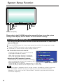
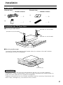
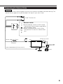
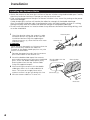
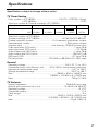
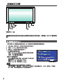
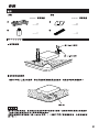
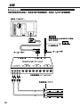
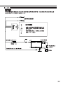
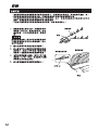
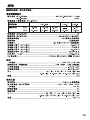
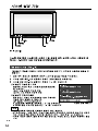
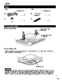
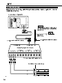
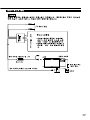
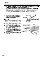
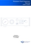
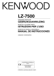
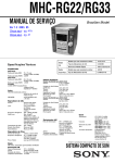
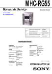
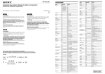
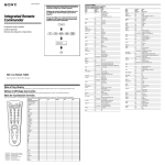
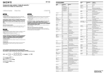
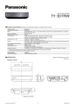
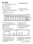
KTC-V800N
KTC-V800P
TV TUNER UNIT
INSTRUCTION MANUAL
© PRINTED IN JAPAN B64-1712-10 (M/H) (DT)
System Setup Function
V.SEL
MODE
SCRN
PWR
+
–
Phone Jack (Ø3.5)
Please refer to the LZ-800W instruction manual for how to use the system
setting screen display and for details on other function settings.
FM Transmitter Function [FM-TX]
You can use the FM transmitter function to hear the sound of the TV, video from
your car FM radio.
1 Press the SCRN button for at least one second to switch to the setup menu screen.
2 Touch [ SYSTEM ] to switch to the system setting screen-1.
3 Touch [ 3 ] to switch to the system setting screen-2.
FM Transmitter Function On and Off
B E E P
O N
OF F
Touch the [ ON ] or [ OFF ] to switch the FM
transmitter function on and off.
F M - T X
O N
OF F
[ON] : FM transmitter function is turned on
[OFF]: FM transmitter function is turned off
F M - T X
Adjusting the FM Transmitter Frequency
8 7 . 5 MHz
When the FM transmitter function is turned on,
RTN
you can switch the transmission frequency (87.5 S Y S T E M
MHz to 89.9 MHz) as follows:
System setting screen-2
Touch the [ 3 ] to increase the frequency by 0.1 MHz step.
Touch the [ 2 ] to decrease the frequency by 0.1 MHz step.
NOTE
• Be sure to select a frequency that is not the same as a broadcast station in your area.
• The “Auto Seek” function on your car radio may not stop at the FM transmitter
frequency. In this case, use the “Manual Seek” function to set the radio to the FM
transmitter frequency.
2
Installation
Accessories
External view
......... Number of items
NA
30
TEN
AN -A3
CX
ITY
ERS TER
OS
DIV
BO
ON
T
F OS
OF
BO
R
CA TH
WI
A
........2
B
........1
External view
......... Number of items
C
........6
D
........2
Installation the TV Tuner Unit
■ Securing to audio board
(Provided with the LZ-800W)
(Provided with the LZ-800W)
(Provided with the LZ-800W)
■ Securing to pile carpet
Arracher les bandes de protection des bandes velcro, les attacher au bas de l’unité de
dissimulation, et fixer à la moquette.
(Accessory D)
2CAUTION
Please do not install the unit near the dashboard, the rear tray, or other important
components. Doing so could lead to injury or accident should the unit come off due to a
shock and strike a person or an important component.
Tapping screws(Provided with the LZ-800W) should be used for mounting. (Attachment with
velcro strips, although easy, can come off with a shock.)
3
Installation
Connecting the TV Tuner Unit
See the LZ-800W instruction manual for details regarding the power harness
and Video Input/Video Output terminals.
Monitor Unit (LZ-800W)
2CAUTION
Extend the antenna cord and locate
in an area where reception is not
marred by excessive noise.
FM-TX
FM transmitter antenna cord
(Provided with the LZ-800W)
(Provided with the LZ-800W)
TV Tuner Unit (KTC-V800N/P)
TV Antenna Unit (Accessory A)
OFF ON
BOOST
CAR DIVERSITY ANTENNA
WITH BOOSTER CX-A330
OFF ON
BOOST
CAR DIVERSITY ANTENNA
WITH BOOSTER CX-A330
4
Connecting the Antenna Units
2 CAUTION
Incar antennas have a lower reception sensitivity than antennas intended for outside mounting. The
picture may not appear or may be disturbed if the signal in your area is weak.
To the TV tuner unit
OFF ON
BOOST
CAR DIVERSITY ANTENNA
WITH BOOSTER CX-A330
OFF
Booster switch
ON
• Set this booster switch to "OFF" if there
is ghosting of the on-screen image due to
electromagnetic fields.
• Please set the booster switch to the
"ON" position in case of a weaken field
area.
Ignition cable (Red) ª12V
ACC
Ignition key switch
Fuse(1A)
Car fuse box
(Main fuse)
Ground cable (Black) · (To car chassis)
–
+
Battery
5
Installation
Installing the Antenna Units
• Attach the antenna to the inner glass surface of the rear window using double-sided tape. Carefully
check the installation location as the tape can only be stuck on once.
• If the surface temperature of the glass of the rear window is low, warm it by turning on the power
of the rear defogger.
A cold window glass surface will weaken the adhesive strength of the double-sided tape.
Also, if installation inside the cabin is performed on a day with high humidity or when it is raining,
the high humidity level will weaken the adhesive strength of the double-sided tape.
• Do not install the antenna in a location where it may obstruct the field of view during driving, such
as on the windshield.
Antenna parts
1 Check the location where the antenna is to be
attached.Clean off any grease or dirt from the
installation location using the supplied glass
cleaner (Accessory B), clean the area with water
and allow to dry.
Antenna unit
2 CAUTION
Clean the glass thoroughly as failure to clean the
glass can not only weaken the adhesive
strength of the double-sided tape, but may also
cause it to come loose.
2 Remove the protective strips from the antenna
parts and the back of the antenna unit.
3 Attach the double-sided tape of the antenna
parts and the antenna unit to the rear windshield
glass. Attach the double-sided tape by firmly
pressing down from the top. Secure cables
using the supplied clampers.
Bundle cables with the
clamper bar
Rear window
4 After attaching the antenna with the doublesided tape, allow it to sit undisturbed for 24
hours. Take care not to apply force to the
antenna or allow it to get wet during this time.
(Accessory C)
5 Wire the antenna cable to TV tuner unit.
Rear seat
6
Specifications
Specifications subject to change without notice.
TV Tuner Section
Color system <KTC-V800P> ....................................PAL(TV) - NTSC/PAL (Video)
<KTC-V800N>........................................................................NTSC
Television system & Channel converge <KTC-V800P>
Television system
Channel converge
PAL-B/G
VHF
2 - 12ch
UHF 21-69ch
1A - 11ch
0 - 12ch
21-69ch
28-69ch
PAL-I
PAL-D
21-69ch
13-57ch
1-12ch
Television system <KTC-V800N> ......................................................................M
Channel converge <KTC-V800N> ....................................2-13ch(VHF)/14-69(UHF)
Channel selection system................................PLL frequency synthesizer system
Demoduration system ............................................................Split carrier system
Antenna input ................................................4-ch diversity (75 Ω /3.5 ø mini jack)
Video input level (RCA jacks)..............................................................1 Vp-p/ 75 Ω
Audio input level (RCA jacks) ................................................................1 V/ 22 KΩ
Video output level (RCA jacks) ..........................................................1 Vp-p/ 75 Ω
Audio output level (RCA jacks) ..........................................................500 mV/ 1KΩ
RGB input (13P) ............................................................................0.7 Vp-p/ 75 Ω
FM transmitter ..........................................87.5 MHz to 89.9 MHz (0.1 MHz step)
General
Operating voltage ..............................................................14.4 V DC (11 to 16 V)
Consumed power (with Monitor unit) ........27 W (25 W: during normal operation)
Operational temperature range ....................................................–10°C to +60°C
Storage temperature range ..........................................................–30°C to +85°C
Size........................................................................188(W) x 30(H) x 144.8(D) mm
7-3/8(W) x 1-3/16(H) x 5-11/16(D) inch
Mass ..............................................................................................780 g(1.7 LBS)
TV Antenna
Output impedance ................................................................75 Ω /3.5 ø mini plug
Booster gain (when booste is on) ......................................10 dB(VHF)/ 6 dB(UHF)
Operating voltage ....................................................................................12 V DC
Consumed current ........................................................................................1.0 A
Cable length ....................................................................................................5 m
Size..........................................................................50(W) x 14.5(H) x 500(D) mm
1-15/16(W) x 9/16(H) x 19-11/16(D) inch
Mass ..........................................................................................70 g(0.1LBS) x 2
7
8
9
10
11
12
13
14
15
16
17
.
18
19