1
E
L
a
I
T
E:
J®
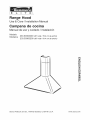
e Hood
Use & Care /Installation
Carnpana
Manual
cocina
Manual de uso y cuidado /instalaci6n
Models
Modelos
233.50303200
(30" wide / 76,2 cm de ancho)
233.50363200
(36" wide/91.4
cm de ancho)
rrl
Z
¢}
rm
Z
m
t_
,,Q
Z_
0
r-
Sears, Roebuck
and Co., Hoffman
Estates,
IL 60179 U.S.A.
www.sears.com
Read and save these instructions .............................. 2
Table of contents .........................................................
2
Warranty ......................................................................
2
Safety instructions .......................................................
3
Operation ....................................................................
4
Cleaning .....................................................................
4
Parts included with hood .............................................
5
Tools needed for hood installation .............................. 5
Parts not included with hood .......................................
5
Equivalent duct length chart ........................................
6
Install the ductwork .....................................................
7
Install mounting bracket ..............................................
7
Install the hood ...........................................................
8
Connect Wiring ...........................................................
8
Connect ductwork (ducted configuration only) ............ 9
Connect ductwork (Non-ducted configuration only)... 10
Service parts ..............................................................
11
Service parts .............................................................
12
If within 1 year from the date of installation, any part of
this range hood fails to function properly due to a defect
in material or workmanship, Sears will repair the part
or furnish and install a new part, free of charge.
FULL 30--DAYWARRANTY ON FiNiSH ON PAINTED OR
BRIGHT METAL PARTS
If within 30 days from the date of installation, the finish
on any painted or bright metal parts of this range hood
is defective in material or workmanship, Sears will
furnish and install a new part, free of charge.
WARRANTY SERVICE iS AVAILABLE BY CONTACTING
THE NEAREST SEARS SEVlCE CENTER/DEPARTMENT
iN THE UNITED STATES.
This warranty applies only while this product is in use
in the United States. This warranty gives you specific
legal rights and you may have other rights which vary
from state to state.
Sears, Roebuck and Co., Dept 817WA, Hoffman
Estates, IL 60179
,_ FOR ORDINARY
RESiDENTiAL
USE ONLY.,_
WARNING _,
WARNING _
Suitable for use in household cooking area.
TO REDUCE THE RISK OF FIRE, ELECTRICAL SHOCK,
OR INJURY TO PERSONS, OBSERVE THE FOLLOWING:
1. Use this unit only in the manner intended by the
manufacturer. If you have questions, contact the
manufacturer at the address or telephone number
listed in the warranty.
2. Before servicing or cleaning unit, switch power off at
service panel and lock service panel to prevent power
from being switched on accidentally. When the
service disconnecting means cannot be locked,
securely fasten a prominent warning device, such as
a tag, to the service panel.
3. Installation work and electrical wiring must be done
by a qualified person(s) in accordance with all
applicable codes and standards, including fire-rated
construction codes and standards.
4. Sufficient air is needed for proper combustion and
exhausting of gases through the flue (chimney) of
fuel burning equipment to prevent backdrafting.
Follow the heating equipment manufacturer's
guidelines and safety standards such as those
published by the National Fire Protection Association
(NFPA), and the American Society for Heating,
Refrigeration and Air Conditioning Engineers
(ASHRAE), and the local code authorities.
5. When cutting or drilling into wall or ceiling, do not
damage electrical wiring and other hidden utilities.
6. Ducted fans must always be vented to the outdoors.
7. Do not use this unit with any solid-state speed
control device.
8. To reduce the risk of fire, use only steel ductwork.
9. This unit must be grounded.
TO REDUCE THE RISK OF A RANGE TOP GREASE
FIRE:
A Never leave surface units unattended at high
settings. Boilovers cause smoking and greasy
spillovers that may ignite. Heat oils slowly on low or
medium settings.
B. Always turn hood ON when cooking at high heat or
when fiambeing food (i.e. Crepes Suzette, Cherries
Jubilee, Peppercorn Beef Flambe').
C. Clean ventilating fans frequently. Grease should not
be allowed to accumulate on fan or filter.
D. Use proper pan size. Always use cookware
appropriate for the size of the surface element.
TO REDUCE THE RISK OF INJURY TO PERSONS IN
THE EVENT OF A RANGE TOP GREASE FIRE, OBSERVE THE FOLLOWING:*
1. SMOTHER FLAMES with a close-fitting lid, cookie
sheet, or metal tray, then turn off the burner. BE
CAREFUL TO PREVENT BURNS. If the flames do not
go out immediately, EVACUATE AND CALL THE FIRE
DEPARTMENT.
2. NEVER PICK UP A FLAMING PAN - You may be
burned.
3. DO NOT USE WATER, including wet dishcloths or
towels - violent steam explosion wilt result.
4. Use an extinguisher ONLY if:
A You know you have a Class ABC extinguisher and
you already know how to operate it.
B. The fire is small and contained in the area where
it started.
C. The fire department is being called.
D. You can fight the fire with your back to an exit.
* Based on "Kitchen Fire Safety Tips" published by
NFPA.
CAUTION
,A
1. To reduce risk of fire and to properly exhaust air, be
sure to duct air outside. Do not vent exhaust air into
spaces within walls or ceilings or into attics, crawl
spaces, or garages.
2. Take care when using cleaning agents or detergents.
3. Avoid using food products that produce flames under
the Range Hood.
4. For general ventilating use only. Do not use to
exhaust hazardous or explosive materials and
vapors.
5. To avoid motor bearing damage and noisy and/or
unbalanced impellers, keep drywall spray,
construction dust, etc. off power unit.
6. Your hood motor has a thermal overload which will
automatically shut off the motor if it becomes
overheated. The motor will restart when it cools
down. If the motor continues to shut off and restart,
have the hood serviced.
7. For best capture of cooking impurities, the bottom of
the hood should be a minimum of 24" and a
maximum of 30" above the cooking surface.
8. Two installers are recommended because of the
large size and weight of this hood.
9. Please read specification label on product for further
information and requirements.
m
3
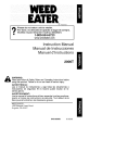
WARNING: To reduce the risk of electric
shock, disconnect from power supply before
cleaning.
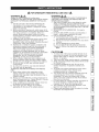
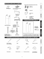
Controls:
LIGHT
SWITCH
I
PILOT
BLOWER
SWITCH
/
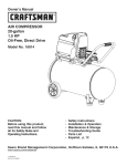
Grease filters
Clean frequently using hot water and a mild detergent or
in your dishwasher. The aluminum mesh filters should
be washed approximately every month depending on the
amount of usage. Wash more often if your cooking style
generates greater grease - like frying foods or wok
cooking.
The hood is operated using the slide controls under the
hood canopy.
The light switch turns the lamps on and off.
The blower switch :makes it possible to select the motor
operating speed. Position 0: motor off.
The pilot lamp lights up whenever the blower is on.
GREASE
Non-ducted
FILTER
charcoal filters
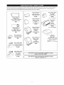
LIGHT BULBS
1. Ductfree filter kit (B03300487) is included.
WARNING: To reduce the risk of electric
shock, disconnect hood from power supply
before changing bulbs.
2. Position the two (2) non-ducted charcoal filters over the
blower.
3. Rotate to lock filters in place.
FILTERS
Stainless
steel
hood surfaces
Stainless steel hoods should be washed regularly with a
clean cloth, warm water and mild soap or dish detergent.
Clean in the direction of the polish lines. Rinse well with
clear water and wipe dry immediately. You may wish to
apply light oil used for furniture polishing to emphasize
it's bright finish.
To change bulbs:
1. Remove the screw securing the light fitting.
2. Pull down tens to remove.
3. Replace with light bulbs of the same type. CAUTION: BULB
MAY BE HOT!
This range hood requires two (2) 40-watt light bulbs (included).
4
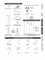
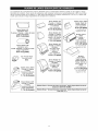
PARTS FOR NON-DUCTED
O
6=inch Round Damper
CONFiGURATiON
w
Filters (2)
Aluminum Grease Filter
(1 per hood)
Flange
MOUNTING BRACKET
Air Baffle
4 Mounting
screws
(3,4 x 15mm
Flat Head)
FLUE MOUNTING BRACKET
PARTS
4 MOUNTING SCREWS
(3,9 x 9,5ram Pan Head)
DECORATIVE FLUE
m
Sears Part
No. 58100
2 MOUNTING
SCREWS
(3,9 x 6 mm Flat
Head)
8 MOUNTING SCREWS
(4,8 x 38ram Pan Head)
Flue
Extension
Kit for
10 ft ceiling
"Parts Not included With Hood" available by calling
Sears at 1-800-4-MY-HOME ®
8 DRYWALL ANCHORS
1
J
{n
O
i
Screwdriver
(Flat & Phillips)
Pencil
Tape
Measure
Wire Stripper
i
Drill
Sabre
Saw
-or-
Keyhole
Saw
Duct Tape
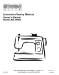
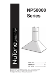
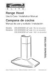
Kenmore range hoods are designed to perform efficiently when attached to long runs of duct. As a point of reference,
this hood will function at approximately 80% of its rated air flow when 150 equivalent feet of 6" round ductwork is
attached. Use this chart to calculate the equivalent duct length of your system.
Broan Model 428
3V4=in, × 10=in,
Sears Model 59691
6=in. Round
Right=angle Elbow
Equivalent length
Wall Cap
Equivalent length
8.5 ft.
Broan
34 ft.
Model 401
(6-ft. w/o damper)
Straight Duct
3V4=in. x 10=in. x 2=ft. long
Equivalent
length
Broan Model 429
3V4=in, × 10=in.
Sears Model
59391
3V4-in. x
10=in.
Right=angle Fiat
Elbow
2 ft.
Equivalent length
24 ft.
Cap
Equivalent length
45 ft.
Broan
(7-ft.
Model 406
3V4=in, × 10=in,
Straight Duct
6=in, round × 2-ft, long
Equivalent
length
2 ft.
w/o damper)
Right=angle
Short
Eave Elbow
@
Equivalent
length
Broan
Model
430
15ft.
Broan Model 419
6=in. Round Elbow
Sears
Model 59091
Equivalent length
Broan Model 431
3V4=in, × 10=in,
Right=angle
Long
Eave Elbow
8ft.
Sears Mode! 59581
3V4=in, × 10=in, to
6=in, Round Transition
Roof Cap
(accepts
7=in. round
or 3Y4=in. × 10=in. duct)
Equivalent length
30 ft. (7-_.wJodamper',
Equi_a;n_ngth
Equivalent length
5.5ft.
Broan Model 412H
3V4=in, × 10-in, to
6=in, Round
Transition
Sears Model "Ducting
Accessories"
available
Sears at 1-800-4-MY-HOME
®
by calling:
i
Broan
by calling:
i
J
Equivalent length
5.5ft.
Model "Ducting
Sears
6
Accessories"
available
at 1-800-558-1711
J
m
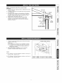
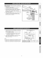
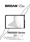
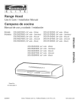
NOTE: To reduce the risk of fire, use only metal
ductwork.
1. Decide where the ductwork will run between the hood
and the outside.
2. A straight, short duct run will allow the hood to perform
most efficiently.
3. Long duct runs, elbows, and transitions will reduce
the performance of the hood. Use as few of them as
possible. Larger ducting may be required for best
performance with longer duct runs.
4. Install a roof or wall cap. Connect round metal
ductwork to cap and work back towards hood
location. Use duct tape to seal the joints between
ductwork sections.
ROOF CAP
,\
6"
ROUND
DUCT
DECORATIVE
FLUE
WALL
CAP
_
6"
HOOD
ROUND
ELBOW
24" TO 30" ABOVE
COOKING SURFACE
C3
O
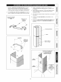
1. Construct wood wall framing that is flush with interior
surface of wall studs.
Make sure:
a) the framing is centered over installation location.
b) the height of the framing will allow the mounting
bracket to be secured to the framing within the
dimensions shown.
2. After wall surface is finished secure mounting
bracket to framing using dimensions shown.
/
FRAMING
BEHIND
DRYWALL
::3
::3
NOTE:
On 8' ceilings, the hood distance
minimum 24", maximum 27".
above
cook top is
On 9' ceilings, the hood distance
minimum 28", maximum 30".
above
cook top is
36=3/4"=
42=3/4"=
bottom
bottom
of
of
hood
hood
24" above
30" above
eooktop
eooktop
m
7
1.
Install the round damper into the duct connector of the
range hood.
2.
Hang the hood from the bracket through the
rectangular cut-out on the back of the hood. Cut-out
is larger than the bracket to allow for horizontal
adjustment.
The bottom of the hood should be 24" to 30" above
the cooking surface.
3.
Attach (2) hood height / angle adjustment screws
(3,9 × 9,5 ram) to hood bracket. Use these screws to
level the hood.
4.
Secure the hood with mounting screws (4,8 × 3,8
ram). Use drywall anchors, provided, if wall studs or
framing are not available.
ROUND DAMPER
HEIGHT
ADJUSTMENT
WALL FRAMING
ADDITIONAL
MOUNTING
_MOUNTING
BRACKET
RECTANGULAR
CUTOUT
Note: This range hood must be properly grounded. The
unit should be installed by a qualified electrician in
accordance with all applicable national and local
electrical codes.
GROUNDING INSTRUCT]ONS
This appliance must be grounded. In the event of an
electrical short circuit, grounding reduces the risk of
electric shock by providing an escape wire for the electric
current. This appliance is equipped with a cord having a
grounding wire with a grounding plug. The plug must be
plugged into an outlet that is properly installed and
grounded.
WARNING - Improper grounding can result in a risk of
electric shock.
Consult a qualified electrician if the grounding
instructions are not completely understood, or if doubt
exists as to whether the appliance is properly grounded.
Do not use an extension cord. If the power supply cord is
too short, have a qualified electrician install an outlet near
the appliance.
Set the electrical power supply within the space covered
by the decorative flues.
Position the power socket at a maximum distance of 337/16" (85 cm) from where the lead exits from the hood
(see illustration alongside). Make sure this does not
interfere with the bracket fastening area or with the
decorative flue (where the flue touches the wall).
Fit the plug into the power socket.
(85cm)
max
m
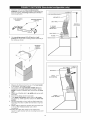
1.
2.
Adjust the width of the flue mounting bracket
assembly to equal the inside width of decorative flue.
Insert and tighten mounting screws (3,9 x 6 ram) to
hold bracket width.
Use mounting screws (4,8 x 38 ram) and wall
anchors to secure flue mounting bracket to the ceiling
as shown.
3.
Use 6" round damper / duct connector to 6" discharge
on hood.
4. Attach 6" round metal duct to connect the duct collar
on the hood to the ductwork above.
5.
Use duct tape to make all joints secure and air tight.
6. Insert the decorative
FLUE MOUNTING
BRACKET ASSEMBLY
7.
flues setting them on the hood.
Extend the upper flue to the ceiling and secure with
two mounting screws (3,9 x 9,5 ram).
MOUNTING
SCREWS (3,9x6mm)
OEOORAT,VE
J
(b
FLUE
E:iii:i::i:iii:iii:iii:i
i /
D U CT TAP
WALL
ANCHORS
MOUNTING
SCREWS
{b
FASTEN FLUE TO
_UPPER
BRACKET
_
WITH MOUNTING SCREWS
UPPER
FLUE
LOWER
FLUE
LOUVERS ON
UPPER FLUE
(Smide down,
inside
of lower
flue)
m
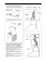
1.
Adjust the width of the flue mounting bracket
assembly to equal the inside width of decorative flue.
Insert and tighten mounting screws (3,9 x 6 ram) to
hold bracket width.
FLUE MOUNTmNG BRACKET _
AIR BAFFLE
FLUE MOUNTmNG
BRACKET
/
MOUNTING SCREWS
(3,gx6mm)
DUCT TAPE
MEASURE &
ADD 6 INCHES
5" ROUND
FLEXIBLE
METAL DUCT
DUCT TAPE
FLANGE
2. Use mounting screws (4,8 x 38 ram) and wall
anchors to secure flue mounting bracket assembly to
the ceiling as shown.
HOOD OUTLET
_
MOUNTING
SCREWS
FLUE
3. Measure the distance from the top of the hood outlet
to the ceiling - and add 6 inches.
4. Cut a piece of 5" round flexible metallic duct (not
included) to the length determined in Step 3. Attach
flange to bottom of flexible duct and secure with duct
tape.
5. Attach top of flexible duct to air baffle and secure with
duct tape.
6. Connect the flange to the hood outlet.
7. Turn upper flue section upside down so air vents
are at the top. Slide upper flue section into lower flue
section.
8. Set flue assembly on hood, with top tilted away from
walt. Align (4) holes in baffle with (4) holes in top flue
section.
9. Attach baffle to upper flue section with (4) screws (3,4
x 15 mm Flat Head)(included). Use a short
screwdriver.
10. Extend the upper flue section to the ceiling and
secure to upper bracket with (2) mounting screws (3,9
x 9,5 mm).
SECTmON
LOWER
-FLUE SECTION
10
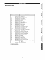
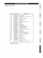
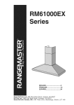
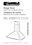
MODEL 50303 - 50363
t_
KEY NO.
9
14
16
26
28
29
45
48
49
53
58**
6O
86
113
114
118
119
120
122"*
145
146
147
151
152
165
165
167
168
195
196
228
229
238
241
4O7
477
PART NO.
B08087292
B02300233
BE3244974
B02300264
B02300280
B03200618
BW0000019
B02310177
B03295076
B03202007
B03295018
B02300248
B08088378
B03202450
B032904990
BE3343338
BE3343339
B08091335
B03295016
B032920170
B032920180
BR2300132
B032920200
B03292200
B03295029
B03295008
B03295030
B03295031
BE3343337
B02011113
B08086255
B03201014
B03295032
B03295033
BE3344985
B03295034
B06001983
B03300487
DESCRiPTiON
Grease Filter
Motor Capacitor
Electrical Box Support
Lamp Bulb (2)
Lampholder (2)
Light Diffuser (2)
Blower
Motor
Blower Wheel
Rubber Washer (3)
Flange
Feeder Cable
Round Damper
Nameplate
Runner Wires
Decorative Flue Bottom
Decorative Flue Top
Flue mounting Bracket
Ductfree Plenum
Feeder cable connection Box
Feeder Cable Connection Box Cover
Junction Clamp
Electrical Box Wires Stop
Feeder Cable Clamp
Electrical Box Switch Assy.
Electrical Box Capacitor
Electrical Box Cover
Feeder Cable Cover
Bracket
Reflector (2)
Controls Board
Warning lamp
Motor Switch Button
Light Switch Button
Blower Support Bracket
Closing
Blower Assembly (Includes Key Nos. 45, 48,
49, 53)
Ductfree filters (2)
* Not shown assembled.
** For Ductfree application.
11
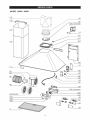
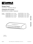
MODEL
50303 - 50363
122
120
119
118
\
113
[_
.
16
6O
.
165 (03295029)
168
167
228
28
229
238
_/_
/
12
Sidentro
de1a_odelafechadelainstalaciOn,
cualquier
partedeestacampana
decocina
dejade
funcionar
enformaapropiada
debido
a defecto
enet
Leayconserve
estasinstrucciones
..........................
13
material
o lamano
deobra,Searsreparar,_
lapieza
Tabladecontenido
....................................................
13
afectada
o proveer,_
e instalar,_
unapiezanuevalibre
Garantia
....................................................................
13
decargo.
Instrucciones
deseguridad
......................................
14
GARANTIA
COMPLETA
DE30 DJAS EN EL ACABADO
Funcionamiento
........................................................
15
EN PIEZAS M ET.,_LICASPINTADAS O ABRILLANTADAS
Limpieza
...................................................................
15
Si dentro de 30 dias de la fecha de la instalaci6n, et
Piezas
incluidas
contacampana
.............................
16
acabado de cualquier parte metalica pintada o
Herramientas
necesarias
parala InstalaciOn
dela
abrillantada perteneciente a esta campana de cocina
campana
...................................................................
16
aparece con defecto en et material o la mano de obra,
Piezas
noincluidas
conlacampana*.
......................
16
Sears proveer,_ e instalar,_ una pieza nueva libre de
Cuadro
delargoequivalente
deconducto
................
17
cargo.
InstalaciOn
dettubodeextraccion
.............................
18
EL SERVlCJO DE GARANTIA SE OB_ENE PONIENDOSE
Instalaci6n
soporte
demontaje
.................................
18
EN CONTACTO CON EL CENTRO DE SERVlCIO O
InstalaciOn
delacampana
........................................
19
DEPARTAMENTO SEARS IVL_,S
CERCANO EN LOS
Instalaci6n
etectrica
..................................................
19
ESTADOS UNIDOS.
Entubado
decanalizaciOn
(ConfiguraciOn
contubo)20
Esta garantJa es valedera unicamente si este producto
Entubado
decanalizaciOn
(ConfiguraciOn
sintubo). 21
se tiene en uso dentro de los Estados Unidos. Esta
Listadepiezas
derecambio
.....................................
22
garantia le confiere derechos legales especificos y Ud.
Listadepiezas
derecambio
.....................................
23
3uede tenet adem,_s otros derechos que varian de
estado a estado.
Sears, Roebuck and Co., Dept. 817WA, Hoffman
Estates, IL 60179
13
INDiCADO
ADVERTENCiA
SOLO PARA EL USO EN COClNAS
_,
ADVERTENCiA
INDICADO PARA EL USO EN COCINAS Domesticas.
Para evitar et riesgo de incendio, cortocircuito o da_o
para las personas, observe atentamente las siguientes
normas:
1. Use esta unidad solamente de la manera indicada
por et fabricante; si tiene dudas, p0ngase en
contacto con este a la direcci0n o tetefono indicados
en la garantia.
2. Antes de hacer una revision o de limpiar la unidad,
desconecteta de la red para evitar que se encienda
de manera accidental. En et caso de que este no
pueda ser desacti-vado, se indicara en la placa de
caracte-risticas.
3. Et montaje y la instalaciOn etectrica debe hacerlos un
tecnico especializado siguiendo las normas
estandar e incluyendo aquetlas de construcci0n anti
incendio.
4. Necesita aire suficiente para una apropiada
combustion y escape de gases a traves det tubo del
dep0sito de quema de combustible. Para evitar que
et humo aspirado vuelva a la cocina, siga las
directivas det fabricante y las normas estandar de
siguridad asi como las normas publicadas por la
AsociaciOn de prevenciOn de incendios (NFPA) y la
Socie-dad americana de especialistas en calefacciOn, refrigeraciOn y aire acondicionado y ademas
las normas de las autoridades locales.
5. Hacer un corte o un taladro en ta pared o en el techo
no debe daSar la instalaci0n etectrica u otras
instalaciones ocultas en la pared.
6. Los conductos ventiladores deben siempre
desalojar al exterior.
7. No use esta unidad con dispositivo de control de la
vetocidad a estado s01ido.
8. Para evitar et riesgo de incendio, use sotamente
conductos de metal.
9. Esta unidad tiene que ser conectada a tierra.
PARA EVlTAR EL R(ESGO DE FUEGO POR ALTO N(VEL
DE GRASA:
A. Nunca abandone los quemadores con el fuego alto.
La cocciOn causa humo y restos de grasa que
pueden arder. Caliente et aceite a fuego medio o
bajo.
B. Encienda siempre la campana cuando cocine a
fuego alto o cuando cocine alimentos facilmente
inftamables. (por ejemplo Crepes Suzette, Cerezas
Jubilee, Ternera fiambeada con granos de pimienta).
C. Limpie con frecuencia los ventitadores. No se debe
acumular grasa en el ventitador o en et filtro.
D. Usa el tamaSp de cazuela apropiado. Use siempre
utensilios de cocina de tamaSo y material
adecuados.
DOMESTICAS.
_,
_,
Para evitar el riesgo de da_os a personas en caso de
fuego por alto nivet de grasa, tenga en cuenta Io
siguiente:*
1. Sofoque la llama con una tapadera apropiada, una
bandeja metalica O un utensitio de cocina que pueda
cubrirla, despues, apague el quemador. Act_e con
precaucion para evitar quema-duras. Si la llama no
se extingue inmedia-tamente, salga y Ilame a los
bombe-ros.
2. Nunca coja una sarten en llamas, porque corre et
riesgo de quemarse.
3. No use agua ni paSos o toallas h[imidas porque
puede provocarse una violenta humareda.
4. Use un extintor solamente si:
A. Posee un extintor de clase ABC y sabe
perfectamente c0mo usarto.
B. El fuego es peque_o y esta controtado en et
mismo sitio en que empez0.
C. Ha Ilamado con anterioridad a los bomberos.
D. Puede combatir et fuego retrocediendo hacia la
salida.
* Basado en "Seguridad antifuego en la cocina"
pubticado por NFPA.
ADVERTENCiA
,_
1. Para reducir el riesgo de incendios y para evacuar
correctamente los humos, asegurarse de haber
realizado una conducci0n del aire hasta et exterior.
No exputsar los humos en espacios cerrados por
paredes o techos, aticos, espacios angostos o
garajes.
2. Prestar la maxima atenci0n al utilizar productos de
limpieza o detergentes.
3. Evitar et uso de productos alimentarios que puedan
inflamarse bajo la campana.
4. S0to para ventilaci0n total. No use gases de escape
peligrosos o materiales y vapores exptosivos.
5. Para evitar daSos en et funcionamiento del motor e
impulsores ruidosos y/o desequi-librados,
mantenga alejados de la unidad de encendido
putverizadores en seco o polvo.
6. El motor tiene un nivel de sobrecarga termica que
apaga automaticamente el motor cuando se ha
recalentado excesivamente. El motor se pone de
nuevo en fincionamento cuando la temperatura baja.
Si et motor comienza a encenderse y a apagarse,
debera hacer una revision de este.
7. Para limpiar mejor las impurezas al cocinar, la parte
inferior de la campana debe estar a una temperatura
minima de 24 grados y maxima de 30 grados pot
debajo de la temperature de la zona de cocciOn.
8. Debido a su gran tamaSo y peso, se recomienda su
montaje por parte de dos tecnicos esperializados.
9. Se recomienda leer la placa de caracte-risticas det
producto para ulterior informaci0n.
m
w
N
m
m
N
14
Mandos:
INTERRUPTOR
INTERRUPTOR
DA LUZ
DEL ASPIRADOR
\
PILOTO
ADVERTENCIA: Para reducir el riesgo de una
descarga electrica, desconecte el suministro
el_ctrico antes de Iimpiar la unidad.
Filtros de malla de aluminio
Limpie frecuentemente los filtros con agua caliente y un
detergente suave. Los fittros se pueden lavar en
lavaplatos. Se debe lavar los filtros de malla de aluminio
aproximadamente cada mes, dependiendo de su uso.
Lavelos con mayor frecuencia si su forma de cocinar
genera mas grasa - como, por ejemplo, frituras o 'wok'.
/
La campana funciona con los controles deslizantes
debajo det techo det revestimiento.
Et interruptor da luz enciende y apaga las lamparas.
de
Et interruptor del aspirador: regula la vetocidad de trabajo
det motor. Posici0n 0: motor apagado.
Et piloto se enciende cuando et aspirador esta funcionando.
FILTROS ANTIGRASA
Filtros al carb6n (configuraci6n sin tubo)
1. Et juego de filtros al carbon (B03300487) es adjunto.
LAMPARAS
2. Coloque los dos (2) filtros al carbon encima det ventilador.
ADVERTENCIA: Para reducir el riesgo de una
descarga el_ctrica, desconecte el suministro
el_ctrico antes de limpiar la unidad.
3. Gire los filtros para ajustarios en su sitio.
!
FILTROS AL CARBON
Superficies de acero ino×idable de la campana
Se debe lavar las campanas de acero inoxidable
periodicamente con un patio limpio, agua tibia y un jabon o
detergente para platos suave. Limpielas en ladireccion de las
lineas de pulido. Enjuaguelas bien con agua timpia y sequela
de inmediato con un patio. Podra aplicarles un aceite leve
utilizado para lustrar muebles para realzar su acabado
lustroso.
Para cambiar las lamparas:
1. Quite et tornillo que sujeta las lamparas.
2. Quiten et plafOn y tiren hacia abajo.
3. Sustituir con lamparas del mismo tipo. ATENCION: LAS
LA,MPARAS PUEDEN ESTAR CALIENTES.
Este tipo de campana necesita (2) lamparas Tipo 40 WATT
(adjuntos).
15
PIEZAS POR CONFIGURACION
O
SiN TUBO
_J
Casquillo
de 6' pulgadas
n_
carbon (2)
Filtroa al
_}(_/
Filtro de grasa de aluminio
(1 por campana)
Adaptador
i
i
Defector de
aire
v}
SOPORTE DE
MONTAJE
w_
4 Tornillos de
montaje
(3,4 × 15ram
cabeza piatta)
SOPORTE PARA EL
MONTAJE DEL TUBO
TUBO DECORATIVO
4 TORNJLLOS
MONTAJE
(3,9 x 9,5ram
redonda)
DE
cabeza
m
Kit del tubo
decorativo
10' Pulgadas
Sears
Cod. N. 58100
2 TORNILLOS DE
MONTAJE
(3,9 x 6 mm cabeza
piatta)
8 TORNJLLOS
DE
MONTAJE
(4,8 x 38ram
cabeza redonda)
8ESCARPIAS
a Sears
i disponibles
Las"Piezas liamando
no incluidas
conalla1=800-4=MY=HOME®
campana" estan
(3
Destornillador
(chato y Phillips)
Cinta
m_trica
Lapiz
Pelador
de cable
i
N
Perforadora
Sierra de punta
=o=
Serrucho de punta
Cinta adhesiva
para conductos
i
16
Lascampanas
decocinaKenmore
fueron
dise_adas
parasudesempe_o
eficiente
cuando
selassujetaa largos
recorridos
deconducto.
Come
puntodereferencia,
estacampana
funcionara
a aproximadamente
et80%desufiujo
deairenominal
cuando
selesujeta61m(200pies)equivalentes
deconducto
redondo
de17.8cm(7").Utiliceesta
cuadro
paracalcutar
etlargoequivalente
deconducto
desusistema.
Broan
Modelo
428
3Y4-puig. x 10=puig,
Acodado con dngulo
a la derecha
Largo equivalente
2.6 m (8.5 pies)
Broan IVlodelo 401
Conducto
recto
Broan
3V4=pulg. × 10=pulg, × 2=pies de largo
Largo equivalente
7.3 m (24 pies)
Broan Modelo 430
3V4=pulg, × 10=pulg.
Acodado
Broan Modelo 406
Conducto
recto
6=pulg. alrededor × 2 pies de largo
Largo equivalente
COl3
alero
.6 m (15 pies)
Equivalent length
Broan
Sears 59581
3V4=pulg, × 10=pulg,
a 6=pulg.
Transici6n
redondo
!Vlodelo Sears
59391
3V4-pulg, ×
10=pulg.
Tap6n de pared
Largo equivalente
14 m (45 pies)
(2.1 m [7-pies] sin
ulador de tire)
corto
6=in. Round Elbow
Modelo
(1.8 m [6-pies] sin
regulador de tire)
y _ngulo a la
derecha
Largo equivalente
0.61 m (2 pies)
8 ft.
10 m (34 pies)
IVlode!o 429
3Y4=puig. × 10-pulg.
Acodado piano son
_ngulo a la derecha
Largo equivalente
0.61 m (2 pies)
Modelo Sears 59691
6=pulg, Tap6n de
pared redondo
Largo equivalente
V
Mode!o 431
3V4=pulg, × 10=pulg.
Acodado
con alero largo
y bngulo a la
derecha
Largo equivalente
4.6 m (15 pies)
Modelo
Sears 59091
Tap6n de tesho
(acepta ducto de
7=pulg. redondo o
de 3V4=pulg. x 10=
pulg.)
Largo equivalente
9.1 m (30 pies)
(2.1 m [7-pies] sin
regulador de tire)
Largo equivalente
1.7 m (5.5 pies)
Broan
IVlodelo 412H
3V4=pulg. × 10=pulg.
a 6=pulg.
Transici6n
redondo
Largo equivalents
1.7 m (5.5 pies)
Modelo Sears "Aecesorios para conductos" estan disponibles
Sears al 1-800-4=MY-HOME ®
Ilamando:
Modelo Broan "Accesorios
Ilamando:
17
para conductos"
1-800-558-1711
estan disponibles
NOTA:
para evitar
el riesgo de incendio, use solamente
material de metal.
1. Decida donde va a colocar et tubo de extracci6n entre
la campana y la parte exterior.
2. Un recorrido de tubo corto y recto permitira a la
campana funcionar de manera mas eficaz.
3. Los recorridos largos de tubo, codos y manguitos
impiden et buen funcionamiento de la campana. Use
et menor nOmero de eltos posible. Para usos
protongados es necesario un tubo de evacuaciOn det
aire de mayor diametro.
4. Instale una cubierta 6 una tapa. Una et tubo de metal
a la cubierta y retroceda hasta la posiciOn de la
campana. Use une cinta para precintar las juntas
entre las partes det entubado.
TAPA DE
TECHO _\
TUBO
TUBO
DECORATmVO_--_
TAPA
PARED
MANGUITO
CAMPANA
M
24" (61cm) A 30"
(76crn) POR ENCIMA
DE LA ZONA DE
COCClON
1. Construya una estructura de madera en la pared que
quedara nivelada con la parte interior de los tacos en
la pared. Asegt_rese de que:
a) La estructura se encuentra centrada por encima
de la instalaciOn det tubo.
b) La altura de la estructura permite fijar et soporte
de montaje en esta estructura siguiendo las
dimensiones indicadas.
2. Una vez que la superficie de la pared este acabada,
sujete et soporte de montaje siguiendo las
dimensiones indicadas.
ESTRUCTURA
DE MADERA EN LA
p,.
PARED
NOTA:
En techos
superior
En techos
superior
de 8',
de la
de 9',
de la
la distancia entre la campana y la parte
cocina debe ser minimo 24", max 27".
la distancia entre la campana y la parte
cocina debe ser minimo 28", max 30".
/a
36-3/4"(96,7crn)
= si la distancia
de coccion
es de 24"(61cm).
42-3/4"(111,9cm)
= si la distancia
de cocci6n
es de 30" (76cm).
entre
entre
la campana
ma campana
y la zona
y ma zona
_w
N
18
1.
Instale el casquillo redondo en et conector de
conducto de la campana.
2.
Cuelgue la campana en el soporte pot et agujero
rectangular en la parte trasera de la campana. Et
agujero es mayor que et soporte para permitir un
ajuste horizontal.
La parte inferior de la campana debe estar de 24" a 30"
por encima de la superficie para cocinar.
3.
Fije (2) la altura de la campana/los
tornillos de ajuste
del angulo (3,9 × 9,5 ram) al soporte de la campana.
Utilice los tornillos para nivetar la campana.
4.
Asegure la campana con los tornillos de montaje (4,8
x 3,8 ram). Si no dispone de tachones de pared ni de
marcos, utilice los soportes de muro de mamposteria
sin mortero suministrados.
CASQUmLLO
TORNILLOS
DE
REGULATOR
DE
LA CAMPANA
ESTRUCTURA
MADERAEN
PARED
DE
LA
TORNILLOS
DE
MONTAJE
SOPORTE DE
MONTAJE
AGUJERO
RECTANGULARE
Nota: Este tipo de campana tiene que set conectada a
tierra cuidadosamente.
La unidad debe instalarla un
t_cnico electricista siguiendo las normas nacionales y
locales.
INSTRUCCIONES DE CONEXION A TIERRA
Este aparato se debe conectar a tierra. En caso de
cortocircuito, la conexiOn a tierra reduce et riego de
etectrocuciOn ya que posee un hilo de descarga a tierra
para la corriente. Este aparato esta equipado con un
cable que posee un hilo de toma de tierra con una clavija
de tierra. La clavija se debe conectar a un enchufe
instalado correctamente y conectado a tierra.
ADVERTENCIA- una cone×i6n a tierra incorrecta puede
provocar riesgos de electrocuci6n.
Consulte a un electricista calificado si no se entienden o
si existe alguna duda sobre la correcta conexiOn a tierra.
No utilice un cable de protongaci6n. Si el cable
proporcionado es demasiado corto, pOngase en
contacto con un electricista calificado para que instale un
enchufe cerca det aparato.
Conecte la alimentaciOn etectrica en et espacio cubierto
por et tubo decorativo.
Cotoque et enchufe a una distancia maxima de 33-7/16"
(85 cm) desde el cable de la campana (vease figura
adjunta). AsegLirese de que no interfiera con et area de la
abrazadera de sujeci6n o con et tubo decorativo (donde
et tubo decorativo toca con la pared).
Conecte la clavija al enchufe.
19
m
1.
Regule et soporte de montaje del tubo de manera
que su ancho coincida con et det tubo decorativo
superior. Colocar y fijar los tornillos de montaje (3,9 x
6 mm) para que et soporte se adapte a dicho ancho.
2.
Use tornillos (4,8 x 38 ram) y escarpias para fijar al
techo et soporte de montaje det tubo como se indica.
3. Pegar amortiguador redondo de 6" (15,24 cm) /
conector de tubo para descarga de 6" (15,24 cm) en
la cubierta.
4. Use un tubo de metal de 6" (15cm) de diametro para
unir et casquitlo que se encuentra encima de la
campana al tubo.
5.
Use cinta para ajustar todas las junturas y que quede
hermetico.
m
CONJUNTO SOPORTE
DE MONTAJE DEL
TUBO
6.
TORNILLOS
DE
MONTAJE
7.
Introduzca et tubo decorativo
campana.
conectandoto en la
Extienda la parte superior del tubo decorativo hacia
et techo y sujeteta con 2 tomillos de montaje (3,9 x
9,5 mm).
m
_
TUBO DECORATIVO
¢o
C,NTA
m,W
ESCARPIAS
TUBO DE METAL
m
DE MONTAJE
(4,8x38mm)
TORN,LLOS
SUJETAR CON TORNILLOS
EL CANAL SUPERIOR A
LA ABRAZADERA
DE
TUBO
SUPERIOR
m
TUBO
INFERIOR
2o
CELOSiAS
DEL
CANAL
SUPERIOR
(deslizarse
hacia
abajo, en la
parte inferior
del
canal)
w
N
e_
Regule
etsoporte
demontaje
deltubodemanera
quesuanchocoincida
coneldettubodecorativo
superior.
Colocar
yfijarlostornillos
demontaje
(3,9x
6mm)paraqueetsoporte
seadapte
adichoancho.
CONJUNTO
SOPORTE DE
MONTAJE DEL TUBO
SOPORTE
DELTUBO
I
TORNILLOS
DE
MONTAJE (3,gx6mm)
CINTE
MEASURE
&
ADD 6 INCHES
Regulador
de
tJro redondo
de
6" pulgadas
CINTA
ADAPTADOR
2.
Use tornJllos y escarpJaa (4,8 × 38 ram) para fijar al
techo et soporte de rnontaje det tubo como se indica.
_--
ESCARPIAS
X_ 1
CASQUILLO
TORNILLOS
DE MONTAJE
REJILLAS
TUBO
SUPERmOR
3.
Midir la distancia desde la parle superior de la salJda
de la cubierta hasta el techo - y aBada 15,24 cm.
4. Cortar un trozo de tubo metalico flexible y redondo
de 5" (12,70 cm) (no incluido) hasta la Iongitud
detallada en et paso 3. Conecte un adaptador a la
parte inferior det tubo flexible y asegurarlo con cinta.
5. Pegar la parte superior det tubo flexible al deflector
de aire y aseguararlo con cinta para tubos.
6. Conectar el adaptador a la salida de la cubierta.
7. Volcar et tubo superior de manera que las rejillas
queden en la parte superior.
8. Colocar el tubo decorativo en ta campana con la
parte alta separada de la pared. Alinear los (4)
orificios det deflector con los (4) orificios del tubo
superior.
9. Pegar la parte superior det tubo al deflector de aire y
(4) tornillos (3,4x15mm cabeza piatta) (incluso). Usar
un destornillador corto.
10. Extienda la parte superior det tubo decorativo hacia et
techo y sujeteta con 2 tornillos de montaje (3,9 x
9,5mm).
TUBO
INFERIOR
21
MODELO
50303 - 50363
n_
m
m
COD. N.
PIEZA N.
DESCRiPCl6N
wB,_
9
14
16
26
28
29
45
48
49
53
58**
6O
86
113
114
118
119
120
122"*
145
146
147
151
152
165
165
167
168
195
196
228
229
238
241
4O7
477
B08087292
B02300233
BE3244974
B02300264
B02300280
B03200618
BW0000019
B02310177
B03295076
B03202007
B03295018
B02300248
B08088378
B03202450
B032904990
BE3343338
BE3343339
B08091335
B03295016
B032920170
B032920180
BR2300132
B032920200
B03292200
B03295029
B03295008
B03295030
B03295031
BE3343337
B02011113
B08086255
B03201014
B03295032
B03295033
BE3344985
B03295034
B06001983
B03300487
Filtro antigrasa
Condensador
Soporte de la caja de instalaciOn etectrica
Lampara (2)
Soporte de la lampara (2)
Tapa de la lampara (2)
Convoyador
Motor
Manilla de motor
Almohadilla antivibraziones (3)
Adaptador
Cabos
Casquillo
Ptaquette logo
Sujeta cabos
Tubo decorativo inferior
Tubo decorativo superior
Soporte de montaje det tubo
Desviador det aire
Caja cabos alimentaciOn
Tapa de la caja cabos alimentaci0n
Terminal
Sujeta cabos
Sujeta cabos
Caja de instalaci0n electrica
Caja de instalaciOn etectrica
Tapa de la caja de instalaciOn etectrica
Tapa cabos alimentaciOn
Soporte
Reflector (2)
Base de los mandos
Pitoto
Mando motor
Mando iluminaci0n
Soporte convoyador
Sierre
Conjunto motor (Incluye los N. 45, 48,
49, 53)
Conjunto Filtros al carbon (2)
Se encuentran por separado.
** Para aplicaciOn Ductfree.
22
m
m
m
m
p,,
r_J
m
MODELO
50303-50363
122
120
119
118
\
113
[_
.
16
6O
.
229
238
_/_
165 (03295029)
168
167
228
28
/
23
Your Home
iiiiiiiiiiiiiiiiiii
ii_¸_
iiiiiiiiiiiiiiiiiii
For repair-in
your home-of
all major brand appliances,
iiiiiiiiiiiiiiiiiii
iiiiiiiiiiiiiiiiiii
lawn and garden equipment, or heating and cooling systems,
iiiiiiiiiiiiiiiiiii
no matter who made it, no matter who sold it!
iiiiiiiiiiiiiiiiiii
iiiiiiiiiiiiiiiiiii
iiiiiiiiiiiiiiiiiii
For the replacement parts, accessories and
iiiiiiiiiiiiiiiiiii
owner's manuals that you need to do-it-yourself.
iiiiiiiiiiiiiiiiiii
iiiiiiiiiiiiiiiiiii
For Sears professional installation of home appliances
iiiiiiiiiiiiiiiiiii
iiiiiiiiiiiiiiiiiii
and items like garage door openers and water heaters.
iiiiiiiiiiiiiiiiiii
iiiiiiiiiiiiiiiiiii
1-800-4-1VlY-HOME ® (1-800-469-4663)
iiiiiiiiiiiiiiiiiii
iiiiiiiiiiiiiiiiiii
Call anytime, day or night (U.S.A. and Canada)
iiiiiiiiiiiiiiiiiii
iiiiiiiiiiiiiiiiiii
www.sears.com
www.sears.ca
iiiiiiiiiiiiiiiiiii
iiiiiiiiiiiiiiiiiii
iiiiiiiiiiiiiiiiiii
Our Home
iiiiiiiiiiiiiiiiiii
iiiiiiiiiiiiiiiiiii
For repair of carry-in items like vacuums, lawn equipment,
iiiiiiiiiiiiiiiiiii
iiiiiiiiiiiiiiiiiii and electronics, call or go on-line for the location of your nearest
iiiiiiiiiiiiiiiiiii
iiiiiiiiiiiiiiiiii_i
iiiiiiiiiiiiiiiiiiii
iiiiiiiiiiiiiiiiiiii
iiiiiiiiiiiiiiiiiiii
iiiiiiiiiiiiiiiiiiii
iiiiiiiiiiiiiiiiiiii
iiiiiiiiiiiiiiiiiiii
iiiiiiiiiiiiiiiiiiii
iiiiiiiiiiiiiiiiiiii
iiiiiiiiiiiiiiiiiiii
iiiiiiiiiiiiiiiiiiii
iiiiiiiiiiiiiiiiiiii
iiiiiiiiiiiiiiiiiiii
iiiiiiiiiiiiiiiiiiii
iiiiiiiiiiiiiiiiiiii
iiiiiiiiiiiiiiiiiiii
iiiiiiiiiiiiiiiiiiii
iiiiiiiiiiiiiiiiiiii
iiiiiiiiiiiiiiiiiiii
8 AR8
® Registered
Trademark / TM Trademark / SMService Mark of Sears, Roebuck and Co.
SM
® Marca Registrada / [M Marca de FAbrica /
Marca de Servicio de Sears, Roebuck and Co.
MC Marque de commerce /
Marque deposee de Sears, Roebuck and Co.
© Sears, Roebuck and Co.
Code 04306897/5