1
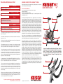
Preventative Maintenance Chart Every Class Member thoroughly inspect each cycle (1) Member wipe off sweat (2) Weekly For The 1st Month Check and re-torque crank arms and pedals (3) Weekly Thoroughly inspect each cycle (4) Clean with warm water and soft towel (5) Check computer for low battery indication (6) Monthly Check and re-torque crank arms and pedals (3) Wax those areas most in contact with sweat (7) Lubricate T-Handle threads used on adjustments (8) 1. Each member should thoroughly inspect each cycle to make sure it is in safe and proper working order. 2. Each member should wipe off their own sweat after each class with a soft towel (their towel) or cloth. 3. Check and retorque the screw holding the crank arm to the axle and the pedals. The torque for both is 35 ft-lbs (47Nm) 4. Thoroughly inspect each cycle to make sure it is in safe and proper working order. Pay particular attention to loose screws, nuts & bolts, crank arms, pedals, pedal cages, handlebar, saddle, T-Handle adjustments, worn pedal straps, etc. 5. Clean with warm water and a soft cloth the parts of the cycle that are dirty or come in contact with sweat. Do not use household or industrial cleaners, because many of them are designed to clean, glass, tile, porcelain, and greasy or oily surfaces and can destroy the protective finish of the paint. If you need to use soap, use a mild dish washing soap followed by an automotive treatment such as Meguiar’s Quick Detailer Mist and Wipe. 6. Check batteries. IF YOU HAVE MULTIPLE BIKES, WE SUGGEST ALL COMPUTER BATTERIES BE CHANGED AT THE SAME TIME (2 AA batteries per bike). See “Computer Battery Replacement” section for instruction. 7. It is not necessary to wax the entire bike monthly, but it is very important to wax those areas that come in contact with sweat and that are the most vulnerable to rust. Use an easily applied automotive treatment such as Meguiar’s Quick Detailer Mist and Wipe. Please note that failure to apply a coat of wax to high sweat areas at least once a month will decrease paint and frame life due to corrosion and will void the warranty. KEISER M3 INDOOR CYCLE WARRANTY TERMS The Keiser M3 Indoor Cycle is warranted to the original purchaser, to be free from defects in materials and workmanship. Not Covered Under Warranty - Loss caused by accident, abuse, improper use or neglect. - Improper maintenance. - Improper assembly by the purchaser. - Failure to follow instructions as stated in any of the manuals provided with the Keiser M3 Indoor Cycle. The warranty terms begin with the date of original delivery to be evidenced by appropriate shipping documents. Any alteration of the equipment so listed without express written consent of Keiser shall constitute a waiver by the buyer of this warranty. This warranty does not cover other brand name products distributed, but not manufactured by Keiser, which are subject to their respective manufacturers warranties. During the warranty period, warranted defects will be repaired at Keiser, Fresno California, or the defective part will be replaced, at the option of the manufacturer, without charge for either parts or labor to repair the defective part. This warranty does not cover the removal of the defective part and installation of the repaired part. All claims under the warranty must be in writing and authorization obtained from the manufacturer, Keiser, to return the defective parts for exchange. Defective parts must be returned to Keiser. The customer is responsible for all transportation costs on returned items to and from the point of manufacture. 1 8 2 The foregoing warranties are in lieu of and exclude all other warranties not expressly set forth herein, whether expressed or implied by operation of law or otherwise, including but not limited to any implied warranties of merchantability or fitness. Keiser shall in no event be liable for incidental or consequential losses, damages or expenses in connection with exercise products. Keiser’s liability hereunder is expressly limited to the replacement of parts not complying with this warranty or, at Keiser’s election, to the repayment of an amount equal to the purchase price of the parts in question. Keiser is not responsible for labor charges incurred in the replacement of defective parts. Keiser may, at its discretion, require the return of all defective parts. The customer is responsible for all transportation costs on warranted items to and from the point of manufacture. Replacement products are warranted for the balance of the original warranty period. 9 3 11 Users, agents, or anyone directing the use of said equipment shall determine the suitability of the product for its intended use, and said parties are specifically put on notice that they shall assume all risk and liability in connection herewith. 4 13 1 Saddle 2 Forward/Backward Seat Adjustment T-Handle 3 Up/Down Seat Adjustment T-Handle 4 Sturdy Base 5 Multi-Function Computer System 6 Resistance Shifter 7 Dual Placement Handlebars 8 Sweat Guard 9 Up/Down Handlebar Adjustment T-Handle 10 Belt Cover 11 Water Bottle Holder 12 Shimano™ Combo Pedals 13 Easy Transport Wheels 5 7 6 555503_A_INSTRUCT - QUICK START & PREVENT (800) 888-7009 keiser.com 12 10 All Keiser equipment sold by Keiser distributors, dealers, or salespeople must be registered for warranty purposes. The warranty registration form must be filed within 7 days of the sale or installation. Keiser equipment exported out of the US or Canada will be void of warranty unless purchased directly through a Keiser international distributor or dealer in the country of installation, or direct from Keiser’s international division. 8. Remove, clean, and lubricate the threads on the T-Handle adjustments. Since both the threaded stud and the threaded nut are stainless steel it is very important to keep the threads lubricated with a heavy grease, preferably white or clear in color, such as Hydrotex MT-55 or Dow Corning 111. If you have any questions please contact our Service Department (800) 888-7009 keiser.com/service.html QUICK START GUIDE The Keiser M3 is a revolutionary new way to cycle, with a focus on power output. The understanding of the M3 resistance system can best be described in the explanation of eddy current resistance and the formula for power (Power = Force x Velocity). The M3 computer is a powerful teaching and programming tool. The computer can assist both the instructor and participant by providing immediate feedback as well as tracking on-going improvement. By experiencing objective cadence, power output, gears and heart rate, the cyclist benefits from a better overall and more effective workout. The computer can also be used as a motivating tool to engage participants in their workouts. The more participants understand the components of a proper workout, the further they can fine tune their performance. The goal is to work more effectively and efficiently, and achieve better results. Understanding Eddy Current Resistance An eddy current is an electrical current in a conducting material that results from induction by a moving or varying magnetic field. On the M3, this is generated by the wheel passing through two opposing magnets. The flywheel (a conductor) passes through the magnetic field generated by the two powerful magnets. By varying how much of the magnetic field comes into contact with the flywheel, the amount of resistance will increase or decrease for the cyclist. This resistance system also allows the cyclist a smoother, quieter, and more predictable ride. 3 4 5 Le s sR To reset your averages during the ride, stop pedalling for three seconds and the averages will start to flash, while they are flashing move the gear lever from bottom to top two times quickly. This will reset your ride information back to zero. 2. Activate the display by rotating the crank pedal. As soon as it is active stop the crank movement. 3. Move the shifter from full retract (lowest resistance) to full advanced (highest resistance) at least five times. These five retractions must be done within five seconds. 4. Computer will indicate it is calibrated by showing “55:55”. If you do not see the “55:55” start over from step # 1. es e anc ist Re Rotating Magnet Housing Mor e Resetting Ride Averages, Elapsed Time and Distance 1. Cycle display must be blank. If the display is not blank wait about 50 seconds until it is blank. 1 To view averages: RPM (cadence), power, and heart rate at any point in the ride, stop pedaling for three seconds. This will flash your averages until you start pedalling again or until the computer goes to sleep after 60 seconds. Computer Calibration 2 ce tan sis Average Calculations 5. Retract shifter (lowest resistance) and computer should show gear “1”. Advance shifter (increase resistance) and computer should show gears changing “1” through “24”. 6. Continue beyond gear “24” and “88” will flash. This is the emergency brake area, where the end of the shifter is about 1” to 1 ¼” off the top of the handlebar. If you do not see the flashing “88” start over from step # 1. Cutaway Revealing Magnet Flywheel Begin Calibration M3 COMPUTER OVERVIEW Calibration Complete M3 RESISTANCE OVERVIEW Line 1 RPM (Cadence) - The RPM display counts the cyclists revolutions per If the flywheel is in less contact with the magnetic field, it is easier to ride. The more of the flywheel that comes in contact with the magnetic field (the higher the energy that is being generated with each turn) the more difficult it becomes to pedal. Another major factor that plays a role in resistance is speed. The faster the flywheel turns, the more energy is generated, and thus the more resistance is created. Power = Force X Velocity Power (amount of work being done in a given amount of time by the cyclist) = force (the amount of resistance) x velocity (the cadence the cyclist is pedaling). This is the same formula that all outdoor cycles follow. By pedalling faster the difficultly increases as the resistance increases. The same applies to the M3, at a set gear the resistance can be increased or decreased by adjusting the cyclists cadence. In this way the M3 cycle is very similar to outdoor cycling. The higher the gear, the higher the cadence the more power produced. minute on one crank arm. RPM is known in the cycling world as Cadence and roughly is the speed at which the cyclist is pedalling. At above 140 RPM the computer will not read and the word “STOP” will appear to indicate that the cyclist is pedalling faster than he or she needs to be. If the cyclist is out of the saddle and wishes to retain sufficient resistance pedalling should not fall below 60 RPM. Line 2 Power - The power output is displayed in Watts (currently generating) and Kilocalories (total value for the ride). The computer toggles back and forth between Watts (displayed for eight seconds) and Kilocalories (displayed for two seconds) throughout the ride. Computer Battery Replacement To test the computer batteries rotate the crank arm until the computer “wakes up”. If the battery is low, a “LO-BA” will display in the odometer (ODO) display at the bottom of the computer. To replace the batteries unscrew the back of the computer housing and remove old AA batteries and replace with a set of two new AA batteries. If you have multiple bikes, we suggest all computer batteries be changed at the same time. Line 3 Heart Rate - If there is no heart rate signal, a steady heart symbol and a zero will be displayed. If a participant is wearing a heart rate strap, and once the computer locks onto the signal, the heart symbol will blink and display the heart rate. Please note that the heart rate strap must be Polar™ compatible and coded. Line 4 Pedaling or Elapsed Time - The number shown reports the total time spent cycling and will reset to zero after 60 seconds of inactivity or if computer is reset using the gear lever. Line 5 Odometer/Trip Distance and Gear - For the first eight seconds when the computer is first activated, the odometer will display the total distance the cycle has been ridden. This feature is for service and maintenance purposes only. After eight seconds, the odometer will display trip distance and gears from 1 - 24. Unscrew Here Lift to Reveal Battery Area