1
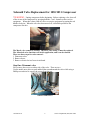
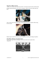
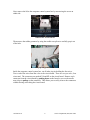
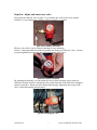
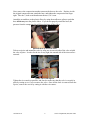
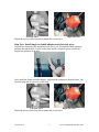
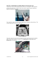
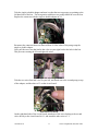
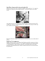
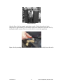
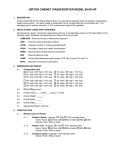
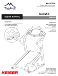
Solenoid Valve Replacement for 1030/1031 Compressor
INTRODUCTION
KEISER CORPORATION has always taken pride in designing and engineering the
highest quality equipment on the market. This means that you will receive years of low
maintenance and minimal repairs from every one of our machines. Only the highest
quality products have the KEISER name on them.
WORD DEFINITIONS
SAFETY CAUTIONS and WARNINGS:
We've put a number of safety cautions in this book. We use the word Caution! to tell you
about things that could cause bodily injury to persons on or around the equipment if you
were to ignore the following instructions and the word Warning! to ensure the proper
installation of components and that the instructions are followed for the safety of the
users and for maximum machine life or the warranty is void.
HINTS:
We use the word Note! in this book to tell you about things that we recommend you
doing or things to be aware of before performing the instructions. These notes were
placed in the manual to aid you during a certain procedure.
Warning!
Failure to follow the assembly or operation instructions as provided by this
manual or any other instructions pertaining to the assembly and/or
operation of KEISER equipment will result in voiding the warranty and
could lead to serious injury.
Tools Required:
½ inch open-ended wrench
needle nose pliers
wire cutter
standard size Phillips screwdriver
These items have been provided: 8 zip ties
2 Allenair® valves
1 single to double adapter
Solenoid Valve Replacement for 1030/1031 Compressor
*WARNING: Unplug compressor before beginning. Before replacing valve, draw all
of the air out of the compressor by pressing both the + and – buttons on the exercise
equipment. When this is done, shut off valve to exercise equipment by turning the red
handle clockwise. When the valve has been turned off, it should be parallel to the
compressor like this:
The Mac® valve cannot be cleaned. Therefore, once faulty, it must be replaced.
The Allenair® valve functions well in this application, and it can be cleaned.
There are three steps for valve removal:
1 Dismount valves
2 Remove hoses
3 Remove electrical wires from circuit board
Step One: Dismount valve
First, remove the screws on either side of the valve. There are two.
Use the needle nose pliers to grab and hold the nut underneath the valve while using a
Phillips screwdriver to remove the screws from the top.
remove both screws
10-5508 Rev A
2
Service Department (800) 888-7009
Step Two: Remove hoses
After the screws have been removed, take the ½ inch open-ended wrench, and loosen the
nut that connects the hose to the valve by turning it counter-clockwise, and remove the
hose.
Unscrew nut counter-clockwise
Next, cut the hose to the plastic elbow 3/8 inch from the end of the plastic elbow using
the wire cutter.
cut tubing
Repeat steps one and two to dismount the second valve before proceeding to step three.
Step Three: Remove electrical wires
First, clip the zip tie that is holding the four wires to the valves outside of the
compressor.
cut ties
10-5508 Rev A
3
Service Department (800) 888-7009
Next, remove the lid to the computer control system box by unscrewing the screw on
either side.
remove two screws on lid
Then remove the rubber grommet by using the needle nose pliers to carefully pop it out
of the hole.
pop out grommet
Inside the computer control system box, cut all other zip ties holding the four wires.
Trace each of the wires from the valve to the circuit board. There are two per valve, four
wires total. The connectors are marked V1 and V2 on the circuit board. Remove each
connector from the circuit board by pushing down on the board as you use the needle
nose pliers to pull up on the connector. This allows you to safely remove the connectors
without flexing or breaking the circuit board.
10-5508 Rev A
4
Service Department (800) 888-7009
1030 Circuit Board Diagrams
Rev A, B, C
10-5508 Rev A
Rev D - Current
5
Service Department (800) 888-7009
push on board, pull on wire
Pull each of the four wires back out the hole one by one. Save the rubber
grommet.
There are four steps to Allenair® valve installation:
1 Adjust and mount new valve
2 Install single to double splitter and electrical wires
3 Secure and tie wires and replace lid
4 Test compressor
5
Note: Keep two things in mind when you are ready to install the new valves.
First, the new valve requires a different mount. Second, the electrical wiring requires the
installation of a single to double adapter on the circuit board.
10-5508 Rev A
6
Service Department (800) 888-7009
Step One: Adjust and mount new valve
First, make sure that the valve is open. Try to turn the pet-cock on the valve counterclockwise. If you cannot turn it further counter-clockwise, it is open.
open valve counter-clockwise
The new valve allows you to rotate its housing for easy mounting.
Use the ½ inch open-ended wrench to loosen the nut on the top of the new valve. Loosen
it just enough that you can rotate the red metal housing of the valve.
turn nut counter-clockwise
By adjusting the housing, you can mount the valve so that each hose easily reaches it,
while the electrical wires are leaving the valve in the direction of the hole in the computer
control system box. When you have adjusted the housing, tighten the nut on top of the
valve, so that the housing does not move.
position housing on valve
10-5508 Rev A
7
Service Department (800) 888-7009
Next, remove the compression nut that connects the hose to the valve. Replace it with
the original compression nut, attach the hose, and tighten the compression nut finger
tight. Take the ½ inch wrench and rotate the nut ½ to ¾ turn.
Attach the second hose to the plastic elbow by using the needle nose pliers to push the
hose all the way onto the plastic elbow. If you do not properly attach the hose, the
pressure from the compressed air will force the hose off the elbow.
push all the way down on elbow
Take two zip ties and mount the valve by using one tie on each side of the valve to hold
the valve in place. In order for the ties to stay tight, the smooth side of the tie must face
outward.
secure valve with zip ties
Tighten the tie as much as possible, and check to make sure that the valve is securely in
place by testing to see if you can move the valve. Once all the slack is removed from the
zip ties, remove the excess by cutting it with the wire cutters.
10-5508 Rev A
8
Service Department (800) 888-7009
Left side valve
Repeat the process under Step One to mount the second valve.
Right side valve
Step Two: Install single to double adapter and electrical wires
Take all four electrical wires and insert them, one by one, through the rubber grommet,
and then through the hole. Pull all of the slack into the computer system control box.
Replace the grommet in the hole.
Next, install the single to double adapter. Approach the compressor from the front. The
electrical plug and air valve are on the front.
Left side valve
Right side valve
Repeat the process under Step One to mount the second valve.
10-5508 Rev A
9
Service Department (800) 888-7009
Step Two: Install single to double adapter and electrical wires
Take all four electrical wires and insert them, one by one, through the rubber grommet,
and then through the hole. Pull all of the slack into the computer system control box.
Replace the grommet in the hole.
Next, install the single to double adapter. Approach the compressor from the front. The
electrical plug and air valve are on the front.
Front of compressor
Grasp the connector located on the left hand side of the circuit board in slot L1 with the
pliers. Remove the connector located in L1 by pushing down on the board while
pulling up on the connector.
push down on board, pull up on connector
10-5508 Rev A
10
Service Department (800) 888-7009
Take the single to double adapter and turn it so that the two top prongs are pointing to the
left hand side of the box. The bent portion with these two prongs should be over the fuse.
Replace the connector with the single to double adapter in L1.
single to double adapter
Reconnect the connector that was removed from L1 onto either of the prongs atop the
single to double adapter.
Next, pull the two wires that lead to the valve on your right back to the hole in the box.
This prevents crossing the left and right side wires.
pull right side wires to grommet
Take the two wires from the valve on your left, and attach one to the second prong on top
of the adapter, and the other to V1 on the circuit board.
attach wires to board
On the right hand side of the circuit board, attach one of the wires leading to the second
valve directly to the circuit board in L1, and attach the other wire to V1.
10-5508 Rev A
11
Service Department (800) 888-7009
Step Three: Secure and tie wires and replace lid
Make sure that all of the slack is inside the computer control system box. Use a zip tie to
bind the wires and hoses on the outside of the box. Use the wire cutters to cut off the
excess.
zip tie all wires and hoses
Next, gather the four wires inside the box, and arrange them so that the small grey LED
on either side of the box is not blocked from view. Tie these wires using two or more zip
ties. Cut the excess from the ties.
secure wires to center of CGS box
Replace the lid on the computer control system box, and return the screw on either side of
the box.
Step Four: Test compressor
Plug the compressor back in, the displays should light up, and if the compressor is below
95 PSI both compressors should start. The compressor should pump up to approximately
117 PSI and shut off. When each motor shuts off, you should be able to feel air blow
through the tube that holds the foam, which is located on the same side as the motor that
has just shut off.
10-5508 Rev A
12
Service Department (800) 888-7009
feel for air flow
After the flow of air has stopped, wait thirty seconds. Slowly lower the air in the
compressor to approximately 95 PSI and the compressor should start. Open the valve by
turning the handle counter-clockwise to allow the air to reach the equipment.
Open valve by turning counter-clockwise until the handle is directly above the valve.
10-5508 Rev A
13
Service Department (800) 888-7009
2470 S. Cherry Ave.
Fresno, CA 93706
1(800) 888-7009
Fax: (559)256-8100
e-mail: [email protected]
www.keiser.com
10-5508 Rev A
14
Service Department (800) 888-7009