1
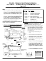
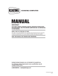
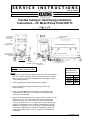
SERVICE INSTRUCTIONS
Part No. 057122
www.keatingofchicago.com
1-800-KEATING
Flexible Tubing to Hard Piping Installation
Instructions – for Motor/Pump Part# 055173
Page 1 of 2
Operation #1 Dis-Assembly
Filter Tub Assembly
See Note #1
Motor/Pump
Housing Covers
See Note #5
(2X)
Motor/Pump
Housing Assembly
Filter Tub Assembly in Unlocked Position
90° Compression
Fitting See Notes
#3 and #5
Filter Cart Frame Assembly
View “A – A”
Pull Rod
See Note #2 Compression Fitting
See Note #3
Bracket SE Coupler
See Note #4
Caution:
Make Sure Saftey Glasses are Worn
Notes:
1. Drain and clean all oil from filter tub assembly. Remove filter tub assembly
from filter cart frame assembly. This assembly will be turned over (upside
down), for replacement of parts and adjustment to mating part on motor
mount housing assembly.
2. Remove pull rod and set aside; this part will be used later.
Use these Service
Instructions for the
following Kit part #’s:
057117
SE14
057118
SE18
057119
SE20
057120
SE24
3. Loosen compression fitting at pump output. Do not remove 90°
fitting from pump.
4. Remove (4) bolts holding bracket SE coupler. This assembly will be
replaced with new parts in kit. The bracket and flex tubing with quick
connect are to be discarded.
5. Inspect 90° compression fitting on the pump as shown in View A – A. If the
fitting is not on center line of the radius on the pump mount housing
assembly as shown, use a #23 or #24 drill to remove pump housing
covers (2) as shown in view A – A, to gain easier access to the top bolts
holding the motor/pump. Loosen (4) bolts on motor/pump to center 90°
fitting as best as possible. These covers will be re-assembled with parts
in the kit. After adjustments are made to the motor/pump to center 90º
compression fitting as shown in view A – A, tighten the (4) bolts for the
motor/pump.
HardPiping057122.qxd
Flexible Tubing to Hard Piping Installation
Instructions – for Motor/Pump Part# 055173 Continued
Page 2 of 2
Operation #2 Re-Assembly
Notes:
1. Remove filter tub from motor/pump housing assembly and set
aside. On 18, 20 and 24 models only, remove pipe nipple 3/8”
NPT x 1” and discard. Replace with pipe nipple 3/8” NPT x 11/2” (item B). See view A for proper dimensions from back of
sump to front of quick connect. On 14” filter tub, see view A
for proper dimesions from back of sump to front of quick disconnect. Place the filter tub into the filter cart assembly.
Release the filter tub away from the pump housing as shown
in side view. Turn the entire assembly upside down as shown
in view B. This step is critical to insure proper alignment
between the motor housing quick connect and the filter tub
quick connect. Use table or bench, making sure the
motor/pump housing is off of the table/bench.
CAUTION: IF FILTER ASSEMBLY IS PLACED UPSIDE DOWN
ON A TABLE OR BENCH, MAKE SURE UNIT IS SECURE, SO
AS NOT TO SLIDE OFF TABLE/BENCH.
Your
Item
A
*B
C
D
E
F
G
*I
J
K
L
M
N
O
Kit Includes (items with * may not be included):
Part #
Qty
Description
-------------------------------056990
1
Pipe Nipple 3/8 NPT 1-1/2 SS-304
056907
1
Bracket Ass’y Haight Baker Pump
020101
8
Nut 5/16 Hex Head Serrated Flang
017142
4
Screw 5/16-18 x 3/4 Hex Head
015227
2
Nut 1/4” Acorn S/S
004611
4
Screw #10 x 3/8 Sheet Metal Pan HD.
037672
A/R
Sealant Locktite 262 (.017 oz.)
056765
8
Washer Flat 7/16” ID x 1.00 OD x .078 THK.
017481
4
Screw 5/16 -18 x 1-3/4 Hex HD SS
X
1
Reinforcement Bracket
015158
2
Acorn Nut 5/16-18 SS
052733
2
Washer 11/32 ID x 3/4 OD
000290
2
Washer, Lock 5/16” Spilt
THIS TIME. Play must be present for proper alignment of
pump housing connect and filter tub quick connect. Slide the
2. Slide item C into position to connect the compression fitting on
filter tub assembly forward until the quick connects are
the pump’s 90° fitting. DO NOT TIGHTEN COMPRESSION
engaged. Tighten items D and E completely. Tighten compresFITTING AT THIS TIME. Attach item C, to the pump housing
sion on item C. Remove (2) bolts and washers “K” and add
with items D and E. DO NOT TIGHTEN COMPLETELY AT
reinforcement bracket “L.” Use longer (2) bolts provided and discard old ones. For 20 and 24 models,
Bottom View
Mount Reinforcement
Pump Mount Cover
add items D and K to reinforcement bracket and
Bracket as Shown
tighten until snug on motor mount housing assemG See Note #4
L
bly (See Bottom View).
Motor Mount Housing Assembly
Filter Tub Assembly
Bolts
Must Be
Flush Not
Tight
3. Attach filter tub pull rod handle using item
F and I.
4. Attach the pump mount covers using item G.
Filter Cart Frame Assembly
Filter Tub Connected
Side View
L
See Note #2
5. Inspect for spacers between casters and filter
cart assembly. If none are present, remove
casters and place item J (2) on the casters
K&D Bolts Only
for Models 20”
threaded stem and reassemble using existing
and 24” See
fasteners and item I.
C
J&I See
Note #5
Note #2
See Note #1
Filter Tub
Pull Rod
See Note #3
K,M,N,O
F&I See
Note #3
B
6. Carefully turn filter assembly to the upright position. Release the filter tub pull rod and check for
proper disconnect. Reconnect the filter tub to
the motor mount housing using handles. If the
assemblies do not connect properly, it will be
necessary to verify notes above were followed
correctly.
See Note A
View A
Support Filter Tub As
Shown to Remove Any
Play Between Tub and
Filter Cart.
D&E
7. Fill filter tub with oil per users manual, cycle oil
to check for leaks at fittings, correct if needed.
Note A Dimensions
9-5/16” for 14” Filter
11-3/8” for 18” Filter
Filter Tub Disconnected
View B
Table or Bench
2-5/8”
Item ‘C’ Detail
12-3/8” for 20” Filter
14-3/8” for 24” Filter