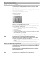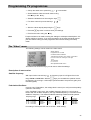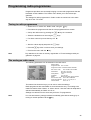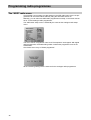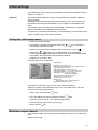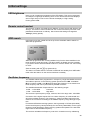
1
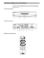
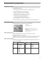
Operating manual
Kathrein Satellite Receiver
UFD 430
Order No.: 260 442
Contents
Controls, displays and connections............................................................................................ 3
View of front panel, rear panel and remote control handset....................................................................... 3
Concise description - front panel, rear panel and remote control handset.................................................. 4
Safety instructions ....................................................................................................................... 5
Important notes regarding operation and place of installation.................................................................... 5
Connecting up and putting into operation.................................................................................. 7
Connecting up the unit ............................................................................................................................. 7
Inserting batteries into remote control handset, UHF tuning ...................................................................... 8
Receiver operation ..................................................................................................................... 10
Switching the unit on ...............................................................................................................................10
Selecting a programme ...........................................................................................................................10
Adjusting volume, balance and tone ........................................................................................................10
Muting the sound.....................................................................................................................................11
Stereo- / Mono- / Channel changeover ....................................................................................................11
Sat/TV changeover .................................................................................................................................11
Setting date and time ..............................................................................................................................12
Timer setting ...........................................................................................................................................13
Daily and weekly repeated switch-on.......................................................................................................14
Video recorder playback (VCR) ...............................................................................................................14
Switching between TV and radio mode....................................................................................................15
Analogue radio programmes ...................................................................................................................15
Digital radio reception (ADR) ...................................................................................................................15
Programme category selection in ADR mode ..........................................................................................16
Additional functions in ADR mode ...........................................................................................................17
Search for ADR radio programmes..........................................................................................................17
Switching back to last programme ...........................................................................................................18
Programme sorting (inserting), swapping and copying .............................................................................18
Operation without remote control.............................................................................................................19
Displaying programme overview..............................................................................................................19
Stop-watch..............................................................................................................................................19
Programming TV programmes .................................................................................................. 20
Tuning in TV programmes .......................................................................................................................20
The “Video“ menu ...................................................................................................................................21
Decoder menu ........................................................................................................................................22
Programme name ...................................................................................................................................23
The “Audio“ menu ...................................................................................................................................23
Programming radio programmes .............................................................................................. 25
Tuning in radio programmes....................................................................................................................25
The analogue radio menu........................................................................................................................25
The "ADR" radio menu ............................................................................................................................26
Initial settings ............................................................................................................................. 27
Calling the initial setup menu...................................................................................................................27
Modulator output channel ........................................................................................................................27
OSD language ........................................................................................................................................28
LNB supply voltage .................................................................................................................................28
Programme selection ..............................................................................................................................28
On Screen Displays (OSD)......................................................................................................................28
LED brightness .......................................................................................................................................29
Remote control handset ..........................................................................................................................29
ADR search ............................................................................................................................................29
Oscillator frequency ................................................................................................................................29
DiSEqC menu .........................................................................................................................................30
22 kHz signal ..........................................................................................................................................31
Tone-burst and DiSEqC-signal ................................................................................................................31
Eeprom read-out and read-in...................................................................................................................33
Switching over remote control’s command set .........................................................................................34
Features ...................................................................................................................................... 35
Specifications ............................................................................................................................. 36
Connection example................................................................................................................... 38
2
Controls, displays and connections
Bedienelemente, Anzeigen und Anschlüsse
This section contains a brief description of all the control elements, displays and
connections. The key symbols presented here are also used when describing the
operating sequences.
View of front panel
View of rear panel
Remote control handset
3
Controls, displays and connections
Front panel controls and displays
Rear panel controls and connections
1
Mains switch (with mains isolation)
1
Mains input socket for 230 V/50 Hz.
2
LED display for TV (8-position, 7-segment display)
Displays programme slot and programme name as well as
menu settings.
2
3
Keys for selecting programmes
Step-by-step programme selection (upwards and downwards).
Switch from standby into operation as well as switchover
from TV to radio mode without using remote control.
DATA socket
a) Connection facility for the external infrared sensor URS
200.
b) Connection for the UFP 10 Copy-Programmer for read-in
and read-out of the programme data.
(function b is especially for service, for copying the
programme data).
VHF/UHF antenna input (signal is looped through).
Remote control handset keys
Function 1:
Command set changeover
Function 2:
To blank out the video signal (in setup mode) This
function is to be used if the picture no longer synchronises on adjustment and the picture scrolls.
Function 1:
Last-function. Allows you to switch back to the last
programme that was selected
Function 2:
Displays the info menu
(active only if after pressing the key
programme list is displayed.)
press in succession)
"
Function 1:
Stores the chosen settings
Function 2:
Primary key for calling up the separate settings menus
(e.g. video settings)
.
Function 1:
Mutes the sound
Function 2:
Calls up the menu for audio settings
4
press in succession)
5
Satellite IF, signal input and
output of LNB supply voltage.
6
Audio output, left and right channel (Cinch sockets).
7
8
Audio digital output (SPDIF output) (Cinch socket)
Scart socket, TV connection
9
Scart socket, VCR connection
10
Scart socket, decoder connection
'
)
Starts a timer
Last-function. Allows you to switch back to the last programme that was selected
Function 1:
On/Off (Standby),
Attention: no mains isolation results!
the
Function 1:
Volume control
Function 2:
To alter settings data in setup mode
(with
VHF/UHF antenna output
(TV signal modulator-output, Ch. 38 is preset).
Function 2:
Return from setup mode into normal operation
Function 1:
Calls up TV programme list (or radio programme list in
radio mode).
Function 2:
Calls up menu for "Programme slot sorting (insertion),
swapping and copying“
(with
3
4
#
&
Set timer, date and time
Function 1:
Selection of TV/SAT mode
Function 2:
Call up the menu for video settings
(with
press in succession)
Function 1:
Step through the programmes either up or down
Function 2:
Selection of individual menu entries in setup mode
Function 1:
Switchover to radio mode
Function 2:
Calls up the menu for radio settings
,
to
(with
press in succession
Stereo/Mono- (2 channel) changeover
Numeric keys 0 - 9 for programme selection and frequency entries
Safety instructions
Sicherheitshinweise
The following section contains important information relating to operation, place of
installation and connecting-up of the receiver.
Read these notes carefully before putting the unit into operation.
Important notes regarding operation
Extended absence / Thunderstorms
Always switch the unit off via its mains switch during periods of extended absence
or at the onset of thunderstorms. This also applies to any other equipment attached
However, take account of any possible timer programming, and switch the unit on
again in good time prior to the recording time.
Mains lead
Make certain that the mains lead (power supply lead) is undamaged. Never put the
unit into operation if the mains lead is damaged.
Cleaning
Withdraw the mains plug before cleaning the unit. Use a dry cloth for cleaning.
Children-at-play
Pay attention that children do not insert objects into the ventilation slots. There is a
risk of mortal danger due to electric shock.
Repairs
On no account remove the housing cover since there are dangerous voltages inside the unit that may be contacted. The unit must only be opened by qualified
specialists, so allow them to carry out any repairs or adjustments to your receiver.
Unauthorised opening entails loss of guarantee.
The electrical safety of the unit can be affected by improper tampering with it
The manufacturer‘s liability excludes accidents occurring to the user when the unit
is opened.
5
Safety instructions
Important notes for siting and installation
Place of installation
Every electronic device generates some heat. The rise in temperature, however,
lies within safe limits. Nevertheless, this does not rule out the possibility of slight
colour changes to sensitive furniture surfaces and veneers over time due to the
constant effect of heat..
In conjunction with treated furniture surfaces, the unit‘s rubber feet can likewise
give rise to changes in colour. Where necessary, place the unit on a suitable pad.
Ventilation
The heat that is generated in this unit is dissipated quite adequately. Never install
the receiver in a cabinet, shelf or rack with inadequate ventilation. Never close-off
the openings on the unit that are intended for heat dissipation.
Do not place objects on top of the unit. Maintain a clearance of at least 10 cm
above the unit so that the heat generated within the unit is convected away without
obstruction.
Mains voltage
Run the receiver only from a mains voltage of 230V / 50Hz.
The unit is not to be connected to the mains until after all the installation work has
been completed.
Humidity
Protect the unit against humidity, drips and splashes.
Solar radiation/heat
Do not place the receiver close to radiators nor expose it to direct sunlight.
Grounding
The parabolic antenna is to be grounded in accordance with regulations. Here, the
relevant German VDE regulations (or equivalent) are to be observed.
LNB supply voltage
If the feeder system (LNB) is supplied with an external supply voltage and the LNB
supply voltage is not used for polarity switchover (e.g. Kathrein single-cable feeder
system UAS 330), the receiver‘s LNB supply must be set to “OFF“ (refer to section:
“Initial settings, LNB supply voltage“).
There is a risk that the receiver may suffer damage if the change-over is not carried
out.
6
Connecting up and putting into operation
Anschluß und Inbetriebnahme
The following section is intended specifically for the specialist dealer. If you are not
carrying out the installation yourself, there is no need to pay any attention to this
section. Sample configurations are to be found in section: “Connection examples“.
Attention
Do not connect the unit to the mains until after the installation work has been carried out properly.
Please note the guidance given in section: “Safety- and Installation Instructions“
Connecting up the unit
Satellite signal connection
• Connect the Sat IF input (5) of the receiver to the satellite receiving system.
For the connection use a coaxial cable with an F-type connecting plug.
If the F connector is not yet fitted to the cable:
• Insulate the cable as indicated in the following illustration, and
• Carefully screw the F connector onto the cable end until it is firmly seated on
the cable.
Attention
When fitting the plug, make certain that none of the fine wires of the braided shield
makes contact with the inner conductor giving rise to a short-circuit.
Receiving system presets
Presetting carried out for the control signals was for conventional receiving systems, thus 14/18 V for polarity switching and 22 kHz switching signal for satellite
selection in the case of multifeed receiving systems.
If DiSEqC or tone-burst switching matrices are to be used in the receiving system,
the default setting must be changed in the initial setup menu at menu entry
“DiSEqC“.
For this, refer to section: “Initial settings, DiSEqC menu“.
Also comply with the technical guide for the multiswitches.
TV and video recorder connection (VCR)
• Connect-up the satellite receiver (TV Scart socket) and TV set with a Scart cable.
If your TV set has stereo capability, a Scart connection allows you to receive the
sound in stereo.
• Connect-up the video recorder and satellite receiver (VCR Scart socket) again
using a Scart cable.
7
Connecting up and putting into operation
UHF connection
If your TV set does not have a Scart socket, the connection to the TV set is made
via a coaxial cable (possibly via the video recorder).
• In this case, pull out the coaxial cable from the antenna input of the video recorder or TV set (if no video recorder is attached) and connect it to the satellite
receiver‘s terrestrial antenna input (view of rear panel, 3).
• Using an additional coaxial cable, connect-up from the satellite receiver‘s TV
socket (view of rear panel, 4) to the video recorder, and from there to the TV
set.
Audio connection
If you want to hear the sound via the hi-fi system, connect the audio Cinch sockets
(view of rear panel, 6) and the hi-fi system with a Cinch cable.
Decoder connection
You can also connect-up a decoder to the receiver for Pay-TV programmes.
No further setting is necessary for decoders that require a video signal and supply
a switching signal, such as Premiere decoder and Videocrypt decoder, for example..
Important
With decoders that do not supply a switching voltage, the video signal path needs
to be set to external at the receiver (see “The video menu“ section in chapter “Programming TV programmes“).
Also comply with the decoder‘s instructions for use!
• Using a Scart cable connect-up the decoder to the decoder Scart socket.
Mains connection
Now connect the receiver to the mains supply using the mains cable supplied for
this purpose.
Inserting batteries into remote control handset
• Remove the cover on the rear of the remote control handset.
• Insert both of the batteries supplied into the remote control handset.
Make certain that the batteries are inserted with the correct polarity! Polarity is
marked at the bottom of the battery compartment.
• Replace the cover again.
Note
8
Exhausted batteries are special waste and should not be disposed of with household refuse. Instead, hand them in to a collection centre for used batteries!
Connecting up and putting into operation
Tuning UHF channel / Checking operation
• Switch on the satellite receiver via the on/off switch on the front of the unit. The
LED display on the unit shows the last programme slot that was selected.
• Turn on your TV set.
• If the satellite receiver and TV set are connected up via a Scart cable, tune in
an audio-visual (AV) programme slot on the TV set.
• With UHF connection via coaxial cable, set up your TV to UHF channel 38 (satellite receiver‘s factory-preset channel) at a spare programme position.
Also take note of instructions in TV set‘s operating manual!
Note
If channel 38 is occupied by a terrestrial broadcast programme or the video recorder, adjust your TV set to a spare UHF channel in the range 21 to 69.
• To avoid interference, when setting the UHF output channel try to ensure that
there is at least one free channel above and below the channel.
• For tuning of UHF output channel at the satellite receiver refer to "Modulator" in
section: "Initial setting".
You can now receive the factory-preset TV and radio programmes. To find out how
to tune in additional TV and radio programmes, refer to sections: “Programming TV
programmes“ and “Programming radio programmes“.
External infrared sensor
If the receiver is to be operated from a location that cannot be reached using the
remote control handset, (with attachment of a further stereo system in another
room, for example), the URS 200 external infrared sensor can be connected up via
the data copy I/O connection (Western modular 8-pole). You can then also control
the receiver from the other room.
Important
All figures in this manual refer to the on-screen display in German. How to
select English as OSD language is described on pages 27 and 28.
9
Receiver operation
Bedienung des Receivers
In this chapter, you learn how to select both TV and analogue and digital radio programmes (ADR) using your receiver, how to adjust the volume and how to programme the timer functions.
In describing the functions, it is assumed that the receiver has already been properly connected up by the specialist.
Should you want to undertake the connections yourself, please read the section:
“Connecting up and putting into operation“ beforehand.
Switching the unit on
on the unit. The last programme
Switch the unit on via the mains switch
mode selected appears (TV, ADR or analogue radio) along with the last programme slot selected. If, before it was last turned off, the unit was switched into
standby, it returns to standby mode the next time it is switched on via the mains
switch.
In standby mode a horizontal line appears in the LED display “ –“.
• The key on the remote control switches the unit between normal operation
and standby.
• You can also turn the unit on using the numeric keys
keys
Note
...
and the channel
.
On switching on via the mains switch, the resulting operating state is always the
same as it was prior to switch-off.
Selecting a programme
• Use the numeric keys
...
to select the desired programme directly.
Example for a three-digit entry (free entry – see initial setting):
Selection of programme slot 147
• 1 is entered, programme slot 1 appears
• 4 is entered, programme slot 14 appears
• 7 is entered, programme slot 147 now appears.
or
• Use the
keys to step through the programmes in succession.
After the programme changeover, the programme slot and programme name are
superimposed on the screen for approximately three seconds.
Note
With the setting “2- or 3-digit programme selection“ there is a switch to the desired
programme after approximately 3 seconds. Digits can be entered during this time
period.
With the setting “free entry“ (in the above example) the receiver switches to the
corresponding programme slot immediately after each input.
In the initial setup menu, a continuous on-screen display of the programme slot can
be selected (see section: “Initial settings, On Screen Displays “).
Adjusting volume, balance and tone
• Use the
keys to adjust the volume to the desired level.
The volume is adjustable in 21 steps. The volume level set appears on the LED
display for approximately 3 seconds. At the same time a bar indicator appears on
the screen.
On Screen Display:
10
LED display:
Receiver operation
VOL
Note
18
The settings are not effective on the VCR Scart socket in order not to disturb any
recordings.
The on-screen display is removed again after approximately 3 seconds.
Whilst the menu for volume adjustment is overlaid, the key can be used to activate the following menu for balance adjustment, tone adjustment, stereo width and
pseudo-stereo .
LED-Display Indicator:
Using the
keys or the
00
BAL
00
TREB
00
BASS
00
WIDTH
00
PSEU
OFF
key you can select the particular menu entry and
then make changes with the
Note
VOL
keys.
In the menu entry “Stereo Width" the stereo base width can be adjusted independently.
“Pseudo-Stereo" can be used to simulate a “stereo-like“ effect with mono programmes, and should thus only be activated with mono reception.
If Pseudo-Stereo has been turned “On“, the stereo width can no longer be altered.
Muting the sound
• Press the
key.
The sound is muted, allowing you to make a phone call undisturbed, for example.
In the LED display the sound muting is displayed with dots . . . . . . . .
• Press the
Note
key again to turn the sound back on.
Mute is not operative on the VCR Scart socket.
Stereo- / Mono- / Channel changeover
TV broadcasts can be transmitted in the two-tone channel method
(e.g. original tone “English" on channel 1, “German" tone on channel 2).
• Press the
key. Each time you press the key, you switch the sound channel in
the order:
Channel 1 → Channel 2 → Stereo .
The selected channel is shown on the screen and in the LED display. The setting is
not saved. After a change in programme the original setting takes effect again.
SAT/TV changeover
Where the satellite receiver and TV set are connected via a Scart cable, many TV
sets immediately switchover signal input (on the Scart socket) to video reception
when the satellite receiver is turned on um. The switching voltage of the TV Scart
socket therefore needs to be switched off if you want to view a terrestrially broadcast TV programme.
• Press the
key.
11
Receiver operation
The switching voltage on pin 8 of the TV Scart socket is turned off, and it is turned
on again by pressing once more.
In Sat mode, “Sat mode“ is displayed on the screen, the programme slot indicator
in the LED display begins with “P...“.
In TV mode, “TV mode“ is displayed on the screen, the programme slot indicator in
the LED display begins with “T...“.
Setting date and time
• Press the
key to call up the menu for date and time setting, and turning the
continuous time display on/off.
The following screen display appears:
In this menu you can set the date and time and also turn on a continuous time display on the screen.
The bottom menu line shows keys you can use to make the settings.
Making the settings
• Select the menu line using the
keys.
The chosen menu entry flashes.
• Change the setting for continuous time display (ON/OFF) using the
keys.
• For the direct entry of numerals use the ... keys.
Always enter the date as 6 positions and the time as 4 positions,
or
• Change the values step-by-step using the
keys.
Saving settings and starting the clock
After entering the time press the
key in order to start the clock.
Return to receive mode
• Press the
key to return to receive mode.
or
• Press the
12
key to continue with the timer programming.
Receiver operation
Timer setting
The unit is assumed to be in normal mode.
• Press the
key twice to call up the menu for the timer settings.
The following screen display appears:
In this menu, you can make timer settings in order to start the receiver at the same
time as a video recorder (e.g. for recordings).
The bottom menu line shows keys you can use to make the settings.
Meaning of the columns
Date
Switch-on date.
Start
Start-time for automatic switch-on.
Stop
Switch-off time.
No.
Number of programme slot.
Making settings
After calling up the timer menu the cursor is positioned at the input line. The active
menu entry is shown by means of a flashing cursor (>).
• For step-by-step entry use the
keys.
or for direct input use the numeric keys ...
.
• When entering values using the numeric keys, enter the date and time with 4and 6 positions respectively, hence “02.01.98" and “08:05" (not “2.1." and “8:5").
Following correct data entry the cursor jumps to the next column.
•
To enter a radio programme slot press the
key first of all.
Saving settings
• Press the
key in order to save your settings.
The values entered are placed in the topmost line of the display. The other entries
are all shifted down by one line.
Making changes
If you want to alter a stored setting, place the cursor in the appropriate line by
pressing the
key. Enter the new data in the usual manner and save the new entries.
To clear a timer that has been set, enter the programme slot as “00“ and save the
entry.
Return to receive mode
• Press the
key in order to return to receive mode.
13
Receiver operation
Note
If the timer becomes active, “RECORD“ is indicated on the LED display for 3 seconds.
During the recording period the programme selection keys are disabled.
If you press a key the following
message appears on the screen:
If the programmed recording time
has ended the following message
appears:
Press the
key if you want the receiver to return to normal operation, otherwise
the unit switches off after 5 minutes.
The programme number in the timer menu is set to “00“.
Attention
Tip
If the timer is programmed for a recording, the unit may no longer be switched off
via the mains switch or else it must be switched on again in good time prior to the
scheduled time of recording. Both the time and the timer settings are maintained
even if the mains is disconnected.
When specifying switch-on and switch-off times, add some leeway to the times so
that the entire broadcast will still be recorded even if programmes are shifted
slightly.
Daily and weekly repeated switch-on
This receiver also allows an optional daily or weekly repeated switch-on.
Daily repeated switch-on
• Enter “00.00“ in the Date column, and also the switch-on and switch-off times.
Weekly repeated switch-on
• Enter the relevant date of the first switch-on day in the Date column, and for the
month enter “00“.
Example:
12.00: the timer is activated for the first time on the 12th day of the month and
weekly thereafter.
Video recorder playback (VCR)
For playback from the video recorder the satellite receiver does not need to be
switched on. Standby mode is sufficient to ensure the signal path is switched
through from the VCR Scart socket to the TV Scart socket.
On playback from the video recorder the LED display shows:
VCR
-with the receiver switched on-in standby mode- VCR.
On playback from the video recorder, you have the possibility of a brief switchover
to satellite reception, in order to check the start of a broadcast, for example, without
needing to switch off the video recorder.
Press the
key for this.
If you press the key once again, each key-press then switches the TV picture in the
following order:
- VCR-playback → Sat mode → TV mode.
14
Receiver operation
Switching between TV and radio mode
Your receiver allows you to receive TV programmes, analogue radio programmes
and digital radio (ADR) programmes.
• After switching on, the receiver is in either the TV mode or the radio mode (depending on the mode at time of switch-off).
•
Press the
key on the remote control to switch between TV- , analogue radio- and ADR radio modes.
Functional sequence:
LED-Display:
TV →
Analogue Radio →
ADR Radio →
P ...
R ...
A ...
TV etc.
With radio mode the screen is blanked out.
Programme selection
Selection of programmes in radio mode is carried out in the same way as for TV
mode.
Analogue radio programmes
Broadcasting of the analogue radio programmes takes place using the recognised
Wegener Panda 1 standard.
Information, such as that for digital ADR radio programmes, is not transmitted in
the case of analogue radio programmes.
The programme name for the analogue radio programmes is entered in the analogue radio setup menu.
Further operation is the same as in the TV mode.
Note
The “Analogue radio“ initial setup menu has a setting that allows a continuous onscreen display of the programme slot. The setting is independent of the setting in
the “TV“ initial setup menu.
Digital radio reception (ADR)
Broadcasting of ADR radio programmes takes place in digital form, i.e. the sound
quality corresponds closely to that of CDs.
With ADR radio programmes, the station name together with a category identifier is
transmitted with the sound signal. Unlike the analogue radio mode, a programme
name does not need to be entered in the case of ADR radio programmes.
With ADR radio programmes, the programme providers can also transmit still further information such as radio-text and TTA data.
This is then also displayed on the screen (after approximately 3 seconds).
TTA data =Title, artist, composer, CD number.
Example:
Note
The displays and overlays appear only if they are included
in the broadcast from the programme provider.
15
Receiver operation
Programme category selection in ADR radio mode
The digital radio programmes are divided up into different categories by the programme provider. The receiver provides the facility for calling up just those broadcasting stations in a certain chosen category.
key .
Press the
The OSD menu appears as follows:
Using the numeric keys
select the desired category.
The receiver switches over to the next programme in the corresponding category.
The OSD menu shows:
LED display:
(briefly for around 3 seconds)
. A 2 .
followed by programme name appearance.
keys, and no longer possiProgramme selection is now possible only with the
ble with the numeric keys (if, in the initial setup menu, programme selection is set
to “Free entry“).
Not all of the programme categories listed in the OSD are offered by programme
providers. If the chosen category does not exist, the following appears briefly:
LED display:
(briefly for around 3 seconds)
________
Following this, the chosen category is displayed, however programme changeover
does not take place.
Selection of a programme is not possible.
To exit from the category mode press the
and
keys in succession
The OSD menu shows:
Programme selection again takes place in
the usual manner.
16
Receiver operation
Additional functions in ADR mode
The UFD 430 receiver provides the facility for displaying the information that accompanies the broadcast, not just in the on-screen menu, but also via the LED display. Display of TTA data via the LED display is done sequentially, which means
that the data is scrolled.
Thus, in ADR radio mode, you have the option of displaying the TTA data and the
radio-text even without the TV set.
Various settings can be made in this connection.
Call up the TTA data menu:
•
Press the keys:
+
In the first menu entry, the scroll interval time of the TTA data records in the LED
display is set. This is adjustable between 1+5 steps.
In the following lines the TTA data records, which are to be displayed when scrolling in the LED display, can be activated.
•
Note:
Selection of menu lines using:
. Activation or deactivation using
.
(press twice).
•
Save with
•
Exit from the menu with
•
To start the automatic data scrolling (of the activated TTA data) in the LED display, press keys
+
in succession .
•
To display individual activated TTA data records and to terminate the automatic data scrolling, press the
key.
.
Only the data records accompanying the broadcast can be displayed.
If both TTA data and radio-text is broadcast, the TTA data for “Album“, “Author“
and “CD No“ is concealed by the radio-text in the OSD menu.
•
Using the keys
revealed.
•
By a further pressing of both keys the radio-text is displayed once again.
+
you can mask out the radio-text. The TTA data is then
Search for ADR radio programmes
If, whilst the receiver is in ADR radio mode, the unit is switched off via the
key
on the remote control (into standby), the search for digital ADR radio programmes
is started automatically.
New stations are appended to the existing ADR programme list. You can then use
the “sort (insert)“ function to sort these programmes as desired. The search run
takes approximately 30 minutes.
The receiver switches into standby on completion of the search run.
Note
The automatic search run can be turned off in the initial setup menu.
17
Receiver operation
Switching back to last programme (swap)
With key
(Last) and key
you can switch back to the previously selected programme and, by a further pressing, switch back again. If you changed programme
using the keys the
programme needs to have been set for at least
10 seconds in order for it to switch back to this programme slot. Otherwise it
switches back to the programme slot last selected with the programme keys.
Programme sorting (inserting), swapping and copying
With the function: “Programme sorting (inserting), swapping and copying“ you can
adapt the programme order in TV- and radio mode to suit your individual requirements.
Example
You want to put the programme from programme slot “P083" into programme slot
“P003" (insert).
• Press the keys
+
in succession.
The menu for function “Insert programme slot" appears.
Options:
Insert programme (sort)
Swap programme
Copy programme
The cursor flashes at the currently selected programme
• Select programme slot P083 using the
...
keys or
keys.
• Move to the right-hand side with the cursor by pressing the key:
.
• Select programme slot P003 using the
...
keys or
keys.
• Press the
key twice.
The programme from programme slot 83 is now transferred to programme slot 3
(inserted).
Following message appears on the screen:
Please wait
When transfer completed, following message appears:
Programme inserted!
Further programmes can be moved using the same method.
• To switch into the “swap“ and “copy“ modes press key
more respectively.
• Exit from the menu with key
once more and twice
.
Radio programmes can be inserted, swapped or copied using the same method in
the respective mode
18
Receiver operation
Operation without remote control
If you happen to have mislaid the remote control handset, you can switch the rekeys on the front of the unit.
ceiver on by simultaneously pressing both
Using the same method you can switch between operating modes: “TV”, “Analogue radio” and “ADR radio”.
Displaying programme overview
The unit is assumed to be in normal mode (TV-, or radio mode)
• Press the
key.
The programme overview appears on the screen.
The currently selected programme is identified by <..>.
•
The
keys can be used to single-step through the programme list while the
keys allow paging in steps of 10.
•
Pressing the
key once results in switchover to the marked programme. On
exiting the programme overview with
key, there is a switch back to the previous programme.
•
Pressing the
key twice results in switchover to the marked programme and
exit from the programme overview.
•
To exit from the menu without selecting a programme press key
.
Info menu
• Press the
key whilst the programme list is overlaid.
The Info menu appears with instructions for calling up the setup menus for the initial setup, video and audio setup.
Exit from the menu with keys
,
or
.
Stop-watch
By pressing
key you can start a stop-watch. A further pressing of the key
removes the stop-watch from the display again.
19
Programming TV programmes
Programmieren von TV-Programmen
The satellite receiver has already been factory pre-programmed for satellite receiving systems with feed systems (receiving system) having 9.75 GHz oscillator
frequency. All of the programmes set up are listed in the table that is enclosed.
If your satellite receiving system uses a feed system with a different oscillator frequency, the receiver only needs to be matched to the feed system oscillator frequency during the installation.
The procedure for this can be found in section: “Initial settings, Oscillator frequency“.
Note on programme memory locations
The receiver has a 250 channel memory that can be assigned with TV or analogue
radio programmes in any manner, and a 250 channel memory for ADR radio programmes.
The analogue section of the receiver has been factory pre-programmed according
to the programme table with
150 TV programmes and
100 analogue radio programmes.
Programme memory is organised here so that the TV programmes are located in
programme slots from 1 upwards, while the radio programmes are located in programmes slots from 250 downwards. See also the following display:
Since only one sound programme (TV accompanying sound or a radio programme)
can be stored in a programme memory, with the factory presetting:
in “TV mode“
on reception of TV programmes in programme slots 151 to 250 the original TV
sound is not sent but instead the programmed radio sound
in “Radio mode“
on reception of radio programmes from programme slots 101 to 250 the sound of
the corresponding TV programme is sent.
The assignment of the programme slots can be changed as desired.
Tuning in TV programmes
To tune in to new TV programmes, the video and audio reception parameters need
to be set up accordingly.
The latest programme assignments can be obtained from satellite programme
magazines, or called up via the videotext of programme Sat 1 from page 675.
• Select the programme slot that you want to change.
• Call up the video menu by pressing the keys
or
20
+
in succession.
Programming TV programmes
• Call up the audio menu: press keys
+
in succession.
• Switch between video and audio menus using
the
key or the
key.
• Select the desired menu line using the keys:
• For direct numeric input use the keys:
.
...
or
• Alter the values step-by-step using the
• Press the
key twice in order to save your settings.
• Exit from the menu using the
Note
keys.
key.
Frequent reference is made to saving the settings in subsequent descriptions. It is
always sufficient, however, if you save the settings in the video and audio menus
just once before exiting from the programme slot or before exiting from setup
mode.
The “Video” menu
The following settings can be made in the video menu:
Setting options:
Programme slot 1 to 250
5-character station identifier
Transmission frequency from 10700...12747 MHz
Hor Low / Vert Low / Hor High / Vert High
1 to 4
16 or 25 MHz
LO 1 to LO 4
See separate decoder menu
The bottom line shows the keys you can use to make the settings.
Description of menu entries
Satellite frequency
With input via the numeric keys
...
, frequency input is in 5-figure form in the
range 10700 to 12747 MHz. With the
keys you can attain the optimum receiving frequency by moving in 1 MHz steps (recommended if the picture is grainy due
to weak signals).
Polarisation/Oscillator
In menu entry “Polarisation“, the voltage level is used (14 or 18V) to set the polarity
(vertical or horizontal).
In the “Oscillator" menu entry, the oscillator frequency group LO 1 to LO4 is selected. With the oscillator frequency the high satellite frequency is converted to the
satellite IF frequency. This allows troublefree matching to different feed systems.
Frequency range
Polarisation
10.70 – 11.70 GHz
10.70 – 11.70 GHz
11.70 – 12.75 GHz
11.70 – 12.75 GHz
horizontal
vertical
horizontal
vertical
LNB
voltage
18 V
14 V
18 V
14 V
Setting
Hor Low
Vert Low
Hor High
Vert High
LO
group
LO 1
LO 2
LO 3
LO 4
LO
frequency
9750 MHz
9750 MHz
10600 MHz
10600 MHz
For setting of LO frequencies refer to section: “Initial setting".
21
Programming TV programmes
Orbit position
In the “Orbit Position“ menu entry, division of the satellites into orbit positions 1 to 4
is carried out.
This dividing up is necessary for the signal selection with the 22 kHz, tone-burst or
DiSEqC switching signal on reception from two (or more) satellites.
The receiver is pre-programmed in accordance with the following table.
Satellite
Astra 19.2° east
Eutelsat 13° east
Eutelsat 10° east
Eutelsat 16° east
Orbit position
1
2
3
4
Switching signal 22 kHz
Off
On
Off
On
In the pre-programming position 1 was again assigned to all other satellites.
Note
In the initial setup menu (DiSEqC menu, menu entry 22 kHz) the particular setting
is specified (frequency band High/Low or orbit position Pos A/B) for which
the 22 kHz switching signal is operative.
Default setting in initial setup menu:
22 kHz signal on for “Pos. A/B“.
Video deviation
The satellites transmit their signals with different video deviation, 16 or
25 MHz. The setting has an effect on the picture brightness.
• Adjust the video deviation to obtain optimum picture brightness.
Decoder menu
You can attach a decoder to the decoder Scart socket for a Pay-TV programme
with video signal.
The receiver recognises Pay-TV programmes for which decoders deliver a switching signal (e.g. like Premiere) independently, and switches this signal through to
the TV- and VCR Scart socket:
For decoders that do not deliver a switching signal, the following setting is to be
carried out
• Call up the video setup menu,
• Select menu entry “Decoder menu“,
• Activate the “Decoder menu“,
Setting option:
Internal / External
Internal / External
• Set the video signal path to external,
• Set the audio signal path to external only if audio signal is encoded as well.
• Save the settings with the
22
key (press twice).
Programming TV programmes
Programme name
In the “Programme name“ line (in the video menu) you can enter a 5-character station identifier of your choice.
• Using the
keys select the menu entry: “Programme name“.
• Using the
keys select the first character.
• With the
key move on to the next character.
• Select the remaining characters in the same way.
• Exit from the menu line using key
• To save the entries press the
• Press the
or
or
.
key twice.
key to be returned to receive mode.
• Move to the first line using the
key and select the next programme slot
The “audio” menu
The following settings can be carried out in the audio menu:
Setting option:
Programme slot 1 to 250
Mode: Mono wide / Mono narrow / Stereo
Frequency:
Sound carrier frequency from 5.00 to 8.98 MHz
De-emphasis: 50 µs / J 17 / dnr,75 µs
Volume Offset: 0 to -3
Audio operating mode
Setting of operating mode: “Mono wide", “Mono narrow" or “Stereo“.
LED display indication: I—I, -II- or O—O.
Operating mode “Stereo“ and “Mono narrow“ is selected on reception of the sound
sub-carrier, “Mono wide“ is selected on reception of the sound main carrier.
Audio carrier frequency
The following is a list of fixed, pre-programmed audio frequencies that can be selected using the
keys.
Mode
Sound carrier frequencies
Mode
Sound carrier frequencies
Stereo
7.02 / 7.20 MHz
7.38 / 7.56 MHz
7.74 / 7.92 MHz
8.10 / 8.28 MHz
Mono (wide)
MWD
5.80 MHz
6.50 MHz
6.60 MHz
6.65 MHz
6.80 MHz
Mono (narrow)
MNR
7.02 MHz
7.20 MHz
7.38 MHz
7.56 MHz
7.74 MHz
7.92 MHz
8.10 MHz
8.28 MHz
23
Programming TV programmes
Input of the audio carrier frequency via the numeric keys ... is in 3-digit form in
the range 5.00 to 8.80 MHz. In stereo mode, the frequency is to be entered for the
left sound channel. The frequency for the right sound channel then automatically
lies 180 kHz above the left sound frequency.
Audio de-emphasis (for sound type “Mono wide” only)
Set the de-emphasis for the best sound impression to “50 µs" or “J17".
In the “Stereo“ and “Mono narrow“ audio modes, the de-emphasis “dnr" with “75
µs" is selected automatically.
Stereo, Mono narrow:
Mono wide:
dnr, 75 µs
50 µs or J17
Volume offset
In this menu entry, you can match the initial setting of the volume to the other programmes and save separately for every programme slot.
Setting range with
keys from 0 to –3.
Saving the settings
•
Save the settings with the
key (press twice).
If you want to make new settings for further programme slots:
• Change over to the “Video menu“ with the
key
• Move to the first programme line, “Programme slot“, and select the next programme slot.
• Select further programme slots in the same manner.
• To exit the setup menu press the
Note
24
key.
You can terminate any setup procedure immediately (also without storing) by returning to normal operation via the
key.
Programming radio programmes
Programmieren von Radio-Programmen
Programme providers are continually bringing out new radio programmes that are
broadcast via the satellites. The “Radio“ menu allows you to store these programmes.
The settings for radio programmes in “Radio“ mode are carried out in the same
way as for the “TV“ mode.
Tuning in radio programmes
• Switch from “TV mode“ into “Radio mode“ using the
key
• First select the programme slot that is to be programmed from scratch.
• Call up the radio menu by pressing the
+
• Select the desired menu line using the
• For direct numeric input use the keys
keys in succession.
keys.
...
.
or
• Alter the values step-by-step with the
• Press the
key twice in order to save your settings.
• Exit from the menu with the
Note
keys.
key.
Pay attention to the note on memory organisation of TV and analogue radio programmes on page 20.
The analogue radio menu
The following parameters can be selected in the radio menu:
Setting option:
Programme slot: from 1 to 250
Programme name: 5-character station identifier
Sat. transm. freq.:
from 10700 to 12747 MHz
Polarisation:
Hor Low / Vert Low /
Hor High / Vert High
Orbit position:
1 to 4
Oscillator:
LO 1 to LO 4
Mode:
Mono wide, Mono narrow, Stereo
Sound carrier freq.: from 5.00 to 8.98 MHz
Audio de-emphasis: 50 µs / J 17 / dnr,75 µs
Volume offset:
from 0 to –3
The bottom line shows the keys you can use to make the settings.
Radio programmes are transmitted on sound subcarriers only. The setting to be
made is therefore either “Stereo“ or “Mono narrow“. Here the audio de-emphasis is
selected automatically as “DNR“ and 75 µs.
Settings are carried out in the same way as for the TV programmes.
Note
You can terminate any setup procedure immediately (also without storing) by rekey.
turning to normal operation via the
25
Programming radio programmes
The “ADR” radio menu
It is generally not necessary to make settings in the ADR radio menu since new programmes can be stored without difficulty using the automatic search run.
Naturally, you can also store ADR radio programmes manually, in the same manner
as for TV and analogue radio programmes.
The "ADR radio" setup menu is essentially the same as the analogue radio setup
menu.
The menu entries "Programme name" and "De-emphasis" are dropped. With digital
radio programmes, the broadcasting station includes the programme name in the
transmission.
One further menu entry is "Delete programme".
All the remaining settings are the same as for the analogue radio programmes.
26
Initial settings
Grundeinstellungen
In the initial setup menu, matching of the satellite receiver to the satellite receiving
system is carried out.
Important
The receiver has already been factory pre-programmed for standard satellite receiving systems.
Alterations to the initial setting are therefore necessary only if your receiving system deviates from this type of installation or if you happen to want different settings.
The settings in the initial setup menu are generally carried out by the specialist
dealer on installation of the satellite receiving system.
To prevent any unintentional alterations in the initial settings, the initial setup menu
can be invoked only from the switched-off state.
Calling the initial setup menu
• Switch the unit into standby.
• Press both the programme selection buttons (2)
multaneously and keep pressed.
on the receiver si-
• Switch the unit on using the standby button on the remote control.
• Release the
buttons when “C 38“ appears on the LED display.
C 38 is the factory preset UHF output channel. If the UHF channel has already
been altered, the appropriate channel selection appears
(between Ch. 21 and Ch. 69).
The initial setup menu is displayed.
Setting options:
Modulator: Channel 21 to 69
OSD language: 3-language German / English /French
LNB supply voltage: Off / On
LNB supply voltage in standby: Off / On
Programme selection: 1-/ 2-/ 3-figure / free entry
OSD display: Off / On (for TV and radio
separately adjustable)
Type of remote control: 26 or 24 keys.
ADR search, see separate menu
Oscillator menu: LO 1 to LO 4
DiSEqC menu:
See separate menu in section “DiSEqC"
EEPROM, see separate menu
The bottom line shows the keys you can use to make the settings.
Settings are made in the initial setup menu in the same manner as in the other
menus for the station programming:
• Select menu entries with the
keys.
• Carry out settings and call up submenus with the
keys
(and use numeric keys .. on inputting frequencies).
• Press the
key twice to save your settings.
• Return with the
key.
Modulator output channel
The modulator‘s UHF output channel can be entered in the range from channel 21
to 69.
Default: channel “38“
27
Initial settings
When making the setting, it should be ensured that there is at least one blank
channel above and below the output channel in order to avoid interference.
OSD language
Here you can select the language for the on-screen displays. The choice available
comprises: German, English and French.
Default: German
LNB supply voltage
Here you can turn off the power supply for the feed system if this is catered for by
an external power supply and signal selection likewise is not carried out through
the LNB supply voltage (e.g. Kathrein single-cable feed system UAS 330).
Note
If there are switchover matrices in the receiving system the LNB supply voltage
needs to be turned in all cases.
Default: ON
LNB supply voltage in standby
When the receiver is in standby the LNB supply voltage is normally switched off.
If terrestrial signals and satellite signals are combined in the receiving system, and
the power supply for the relevant components comes from the receiver, this power
supply must also be guaranteed when the receiver is in standby.
In this case switch the power supply in standby to “On“.
Default: “Off“.
Programme selection
You have the option of entering the programme number in one-, two-, or three-digit
form or as unrestricted input
Default: ”free“.
Note
Setting
Settable programme slots
One-digit input
Two-digit input
Three-digit input
Free input
Programme slots 1 to 9
Programme slots 1 to 99
Programme slots 1 to 250
Programme slots 1 to 250
If a recording is pre-programmed in the timer for a programme slot ≥100, the timer
must be cleared first in order that a change in the programme slot entry can be carried out.
On Screen Displays (OSD)
Here you can select whether the programme slot and programme name are to be
displayed continuously, or whether they are to be removed again approximately
three seconds after programme changeover.
This setting can be made differently in TV mode and radio mode.
Default:
TV mode
“Off“.
Analogue radio mode
“On“.
To call the initial setup menu in analogue radio mode, the receiver must be
switched into radio mode before being switched off. Then call the initial setup menu
in the usual way.
28
Initial settings
LED brightness
Here you can increase the brightness of the LED display. This may be necessary,
for example, if bright light is beaming down on the receiver and the LED displays
are no longer easy to read. In this case set the display to “High“ setting.
Factory preset: Low
Remote control handset
The receiver contains command sets for Kathrein remote controls with both 24 and
26 keys. The remote control included with the receiver has 26 keys and this is the
predefined command set on delivery. Hence leave this setting unchanged as
“26 keys“ (factory preset).
ADR search
In this menu entry the criteria can be set up for the automatic station search for
ADR radio programmes.
ADR radio programmes are currently radiated only from the Astra satellites in the
lower frequency band (low band). The above setting is already set up accordingly.
If you want to switch off the automatic search run, set the “Search run” menu entry
to “OFF”.
Save the setting with the
key (press twice).
The search run starts when the receiver is switched into standby from “ADR radio”
mode. After the search run the receiver switches to standby.
Oscillator frequency
The satellites radiate their programmes in a frequency range that satellite receivers
are unable to process. In the receiving system (known as the LNB - Low Noise
Block converter or LNC - Low Noise Converter) this frequency is converted into a
lower frequency that can be processed by satellite receivers.
The satellite transmission frequencies lie in the following ranges:
10700 ... 11700 MHz
11700 ... 12750 MHz
Low-band
High-band
The receiver‘s input frequency range, however, lies in the range: 920...2150 MHz
Conversion of the higher frequencies into a lower frequency is achieved with the
aid of the oscillator frequency (LO frequency). Various oscillator frequencies are
used for the conversion according to the satellite frequency range and type of system.
For Astra and Eutelsat receiving systems, this is generally 9.75 GHz (9750 MHz)
for the lower frequency band (low-band) and 10.6 GHz (10600 MHz). for the upper
frequency band (high-band). Older receiving systems still operate in the low-band
region with 10 GHz oscillator frequency.
The receiver calculates the frequency onto which it needs to tune by subtracting
29
Initial settings
the oscillator frequency from the satellite transmission frequency stored for each
programme.
As a result, you can easily install the UFD 430 on other receiving systems without
needing to reprogramme every single programme slot.
You only need to set up the particular oscillator frequencies that your receiving
system uses.
On delivery the oscillator frequencies set up are those listed in the picture below.
Changing the oscillator frequency
• Call the initial setup menu (see paragraph: “Calling the initial setup menu“).
• Using the
keys move to menu entry:
“Oscillator menu . . .“.
• Call up the “Oscillator selection“ submenu using the
keys.
• Move to the line in which you wish to alter the oscillator frequency (LO 1.. LO 4).
Various fixed pre-programmed LO frequencies can be selected with the
keys.
• You can enter deviant oscillator frequencies in the range from 9000 MHz to
12000 MHz directly via the numeric keys ... in 5-digit form,
(e.g. 11700).
• Save the settings with the
• Exit from the menu with the
key (press twice).
key.
DiSEqC menu
Fundamentals of the DiSEqC signal (Digital Satellite Equipment Control)
In order to select the satellite signals different control signals are required.
Up until now, the 14/18V LNB supply voltage and the 22 kHz signal (superimposed
on the LNB supply voltage) have been sufficient for signal selection for the majority
of applications.
With these four control criteria it is possible to switch between horizontally and vertically polarised signals, as well as between two satellites (multifeed reception).
With the extension of the frequency range to the 12 GHz region (high-band region
11.70 – 12.75 GHz) or for reception of more than two satellites, additional control
criteria are required for LNB selection and signal selection.
The “DiSEqC“ control signal has been developed by Eutelsat in collaboration with
Philips.
The “DiSEqC“ control signal is actually a particular form of modulation (pulse-width
modulation) of the already existing 22 kHz signal.
The UFD 430 receiver is equipped with:
• DiSEqC tone burst
(also termed Simple DiSEqC or DiSEqC)
and
30
Initial settings
• DiSEqC 1.1
The required setting is dependent on the components of your receiving system.
Settings in the DiSEqC menu
• Call the initial setup menu (see paragraph “Calling the initial setup menu“).
• Using the
keys move to menu entry “DiSEqC menu . . .“.
• Activate the submenu “DiSEqC menu . . .“ using the
keys.
The following menu appears (factory preset):
Setting option:
22 kHz signal: Off, High/Low, Pos A/B
Tone burst:
Off, Pos A/B, Opt A/B, High/Low
DiSEqC:
Off, On
DiSEqC Repeat: Off, 1 or 2
UFO mini:
Off, On, UFO twin 1, UFO twin 2
Remote frequency:
0-2150 MHz
UFO micro:
Off, On, Reset
The bottom line shows the keys you can use to make the settings.
22 kHz signal
In this menu entry, you specify whether the 22 kHz signal is to be used to switch
between a satellite‘s lower and upper frequency range (low/high) or to switch between two satellite positions (Pos. A/B).
22 kHz
High/Low
or
Freq. range
22 kHz
Low
High
22 kHz
Pos. A/B
Orbit Pos.
22 kHz
Off
1 and 3
Off
On
2 and 4
On
(factory presetting)
See also video setup menu, menu lines: Polarisation and Orbit Position
Tone-burst and DiSEqC-signal
If more than four control criteria are needed in a receiving system, a
DiSEqC control signal is required.
Which of the two setting options is required: “Tone Burst“ or “DiSEqC“
depends on the components of the receiving system.
Thus take into account the specifications of the components present in the receiving system (switch-over matrices).
31
Initial settings
Tone burst
In the “Tone burst“ menu entry the following settings of the 22 kHz signal are possible:
Switching states on setting:
Switching states on setting:
—> High/Low and
—> Pos. A/B:
22 kHz signal
Tone burst
Low
High
22 kHz
22 kHz
Off
On
Pos. 1
Pos. 2
Tone burst
Tone burst
0
1
22 kHz signal
Tone burst
Switching states on setting:
—> Pos. A/B and
—> Opt. A/B
Pos
Tone burst
22 kHz
1
2
3
4
0
0
1
1
Off
On
Off
On
22 kHz signal
Tone burst
—> Pos. A/B and
—> High/Low
Low
High
Tone burst
Tone burst
0
1
Pos. 1
Pos. 2
22 kHz
22 kHz
Off
On
DiSEqC
Up to 16 inputs can be switched with the “DiSEqC“ control signal.
If the receiver is connected up to a “DiSEqC" switch-over matrix, the menu entry
must be set to “On”.
Default: OFF
Note
For optimal usage it is essential to know the switching criteria and the input assignments of the DiSEqC switching matrices.
Thus take into account the specifications of the DiSEqC switching matrices or get
in touch with the installer of the receiving system.
DiSEqC Repeat
If the receiver is operated on a receiving system with two or more DiSEqC switching matrices connected in series (cascaded), the DiSEqC command must be repeated.
• In this case set the menu entry “DiSEqC Repeat" to “1" or “2“.
Default: Off
UFO mini
With a “subscriber-controlled preprocessing system" the receiver‘s input frequency
is adjusted to a fixed input frequency. The signals are transmitted by the “subscriber-controlled preprocessing system“ on this frequency. The reception parameters for the programme selection are transmitted by “DiSEqC“ command
to the receiving system and set up there.
Which setting needs to be selected "On", “UFO twin 1“ or “UFO twin 2“ is dependent on the design of the “subscriber-controlled preprocessing system“.
The “UFO mini Twin“ design is a special form of the “subscriber-controlled preprocessing system“
Note
The setting is therefore to be made according to information in the “subscribercontrolled preprocessing system“ installation guide.
Remote frequency
If you have set "On" or “UFO twin 1“ in menu entry UFO mini, make the setting in
this menu entry for the transmission frequency.
The particular transmission frequency that needs to be set in the range 0 to 2150
MHz, is given in the “subscriber-controlled preprocessing system“ installation
guide.
Note
32
It is therefore essential to note the installation guide instructions of the “subscribercontrolled preprocessing system“.
Initial settings
UFO micro
The setting in this menu entry is also designed for operation of the receiver on a
pre-processing system.
Here control and communication between the receiver and the Kathrein “UFO micro" system is effected via the return path of the coaxial cable.
If the UFD 430 receiver is operated on a “UFO micro“ receiving system, an “On"
setting must be made in menu entry “UFO micro".
A special address is then assigned to the receiver by the receiving system during
installation, so that the control commands sent to the receiving system for signal
selection are also recognised by it.
A remote frequency does not need to be set up in this mode of operation since this
is determined by the “UFO micro" system with the addressing.
If the receiver is used on different receiving systems the previously assigned address is to be deleted. This is done in menu entry “Reset".
As a result, the receiver is then assigned the factory-preset address once again
(virgin address). Following this, the “On" setting should be made again. The receiver is then given a new address by the new system.
Note
The pre-programming is not cleared on “Reset".
Default: Off
• Press the
key twice to save your settings.
• Exit the initial setup menu with the
Note
key (press twice).
If you exit the menus without saving, the settings will be lost.
EEPROM
This menu entry is intended for service personnel only.
It allows the programme data to be read out or read in to the receiver by means of
the UFP 10 Copy Programmer.
33
Initial settings
Switching over remote control’s command set
The remote control handset contains two command sets. This allows two receivers
to be operated independently in a room (not in conjunction with a twin receiver).
Note
Switchover is possible for remote controls that have 24 and 26 keys.
For this purpose, programme one receiver on command set 1 and the second receiver on command set 2.
• Switch on receiver 1. Switch off receiver 2 using the mains switch
unit.
⇒ Press the
on the
key and keep it pressed.
⇒ Using the numeric keys
...
enter “901“.
• To adopt the code switch receiver 1 into standby using the
key, and then
switch the receiver off using the mains switch
on the unit.
• Set receiver 2 back into operation.
⇒ Press the
key and keep it pressed.
⇒ Using the numeric keys
...
enter “902“.
• To adopt the code switch receiver 2 into standby using the
key, and then
back into operation again. Set receiver 1 back into operation as well.
⇒ Press the
key and keep it pressed.
⇒ Using the numeric keys
Note
...
enter “903“.
With the first two settings the remote control must be pointer towards the respective receiver which is switched on.
key you can now switch between the two command sets A and B (togWith the
gle function) and operate the two receivers in alternation.
On delivery command set 1 is always active.
Note
If you are using only one receiver and the active command set has been switched
over inadvertently due to maloperation rendering the receiver inoperable, the remote control can be switched back to command set 1 without difficulty. The procedure for this has already been described above.
Note
With remote control handsets that have 24 keys (remote controls of the 200-series
receivers from Kathrein) code numbers 001, 002 and 003 are to be entered in
place of codes 901, 902 and 903.
34
Features
The UFD 430 receiver is equipped with the following features:
• Reception of TV, digital (ADR) and analogue radio programmes
• 250 programme channel memory for TV- and analogue radio programmes
• 250 ADR radio channel memory
• Automatic station search with storing of ADR radio programmes in standby
mode
• Satellite input frequency range from 920 MHz to 2150 MHz
• Freely selectable oscillator frequencies, therefore suitable for all feed systems
• 4 event, 1-year programmable timer, with daily and
weekly repeated switch-on
• Mains switch with mains isolation
• Power failure protection for date and time by lithium battery
• Radio button
• Stereo / Dual tone switchover
• On-screen display (OSD) 3 languages (German, English and French)
• 8-character, 14-segment display for programme slot, programme name and
ADR info data (e.g. station identifier, title, artist, album etc.)
• 22 kHz control signal, programmable
• DiSEqC 1.1 and tone-burst control signal
• LNB supply voltage can be turned off
• Sort- (insert), swap- and copy function for programme slot
• Audio frequency range 5.0 MHz to 8.8 MHz
• Sound muting
• Volume control and also controls for balance, tone and stereo width
• Dynamic noise reduction (DNR) – Wegener Panda
•
Coaxial digital output in SPDIF- format
• Connecting socket for data copying function
(read-in and read-out of programme data with the “Copy Programmer“)
• Connector available for URS 200 external infrared sensor
• 3 Scart sockets for TV-, VCR- and decoder connection
• PLL modulator
• Audio outputs via Cinch sockets
• Infrared remote control with command set changeover (allowing independent
operation of two receivers in a room.)
• Standby power consumption ≤ 2 watts
• Last-status memory
35
Specifications
Technische Daten
UHF characteristics
Sat-IF frequency range
Input level range
IF frequency
IF bandwidth
FM threshold
920 to 2150 MHz
48 to 78 dBµV
479.5 MHz
27 MHz
7 dB max.
Frequency range
Output voltage
20 Hz to 5 MHz
Video
De-emphasis
S/N
1 Vss / 75 Ω
CCIR Rec. 405 / 625 lines
54 dB typ.
Audio (digital)
Standard
Audio carrier frequency range:
Tuning:
Bandwidth:
Frequency range:
Distortion factor (1kHz):
S/N (A-curve):
Output voltage:
Bit error rate (9 dB C/N):
ISO/IEC 11172-3 (MPEG-1/Layer II)
0.18 – 8.82 MHz
Search run, direct input
and adjustable in groups
130 kHz
20 Hz - 20 kHz
<0.03%
>91 dB
1 V into 10 kΩ
-6
10
Audio (analogue)
Subcarrier frequency range
Bandwidth
- Mono wide
- Mono narrow / Stereo
Frequency range
De-emphasis
Output voltage
Distortion factor
S/N
5.0 to 8.98 MHz
280 kHz
150 kHz
40 Hz to 15 kHz
DNR 75 µs / 50 µs / J17
1V / into 10 kΩ (TV-Scart and Cinch)
<1.0 % (at 1 kHz)
>70 dB
Modulator
Standard
Output channel
UHF output level
CCIR PAL G
PLL tuning
settable from channel 21 - 69
(presetting channel 38)
71 dBµV ± 6 dBµV
Power supply
Mains voltage
Power consumption
Power consumption in standby
LNB supply voltage
LNB supply current
Control signal
36
230 V ±10%, 50 Hz
21 W
2W
0, +14 V (vert.), +18 V (hor.)
400 mA max.
22 kHz square-wave
0.6 Vss
DiSEqC 1.1
Tone burst
Specifications
Connectors
Sat IF input
F-socket 75Ω
Modulator
- Input
- Output
IEC socket 75 Ω
IEC plug 75 Ω
TV connection
VCR connection
DECODER connection
Audio-digital (SPDIF output)
Audio
Data interface
Scart/Peritel socket, 21-way
Scart/Peritel socket, 21-way
Scart/Peritel socket, 21-way
Cinch socket
Cinch sockets
Western 8-way
Unit dimensions (B/H/D)
Weight
310 / 71 / 165 mm
Approx. 1.3 kg
Ambient temperature
+5 °C ... 40 °C
General
Temperature range
Accessories
Infrared remote control, mains cable,
2x 1.5 V batteries, Type: LR 03, size: AAA (micro)
Scart connector pin designations
Signal
Pin No.
TV
VCR
Decoder
Right audio output
Right audio input
Left audio output
Audio ground
Blue ground
Left audio input
Blue signal output
Switching voltage
Green ground
Data signal
Green signal output
Data signal
Red ground
Data ground
Red signal output
Blanking signal
Video ground
Blanking signal ground
Video output
Video input
Connector shielding
1
2
3
4
5
6
7
8
9
10
11
12
13
14
15
16
17
18
19
20
21
X
X
X
X
X
X
X
X
X
X
X
X
X
X
X
X
X
X
X
X
X
X
X
X
X
X
X
X
X
X
X
X
X
X
X
X
X
X
X
X
X
X
X
X
X
X
X
37
Connection examples / Service note
The best picture quality is obtained if you connect the satellite receiver, TV set and
video recorder by means of Scart cables.
A stereo TV set also allows you to receive the sound in stereo.
The Sat receiver can be connected to a TV set and video recorder and also a decoder for Pay-TV programmes (e.g. Premiere) via Scart cables.
A hi-fi system is connected up for reception of analogue and digital (ADR) radio
programmes.
In addition, a digital-audio-tape can be connected to the electrical SPDIF output of
the receiver for reception of ADR radio programmes.
Connection of Sat receiver to TV set and video recorder with coaxial cables.
Note
Dear customer
In the unlikely event that you should experience problems with your receiver,
please contact your local specialist dealer.
38
Subject to alterations!
935.2076/04.98/SKS/der
KATHREIN-Werke KG x Telephone +49 80 31 18 40 x Fax (0 80 31) 18 43 06
Anton-Kathrein-Straße 1-3 x P.O.B. 10 04 44 x D-83004 Rosenheim