1
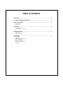
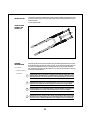
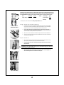
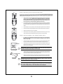
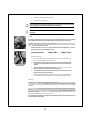
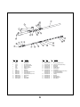
Noleen
Chubby / Chubby LT
Owner’s Manual
1998 CHUBBY / CHUBBY LT OWNER'S MANUAL - PDF
TABLE OF CONTENTS
Introduction . . . . . . . . . . . . . . . . . . . . . . . . . . . . . . . . . . . . . . . . . . . . . . . . . . . .2
Your Noleen Chubby and Chubby LT . . . . . . . . . . . . . . . . . . . . . . . . . . . . . . . . . . .2
General information . . . . . . . . . . . . . . . . . . . . . . . . . . . . . . . . . . . . . . . . . . . . . . 2
Read This Manual!
Precautions
Installation . . . . . . . . . . . . . . . . . . . . . . . . . . . . . . . . . . . . . . . . . . . . . . . . . . . . .3
Frame Preparation
Fork Preparation / Installation
Suspension Tuning . . . . . . . . . . . . . . . . . . . . . . . . . . . . . . . . . . . . . . . . . . . . . . . 6
Tuning Variables
Tuning Adjustments
Maintenance . . . . . . . . . . . . . . . . . . . . . . . . . . . . . . . . . . . . . . . . . . . . . . . . . . . .8
Tools Needed
Lubrication
Seal and O-Ring Replacement
Bearing Replacement
Maintenance Schedule
Torque and Lubrication Table
Service Kits
INTRODUCTION
Congratulations! You’ve just purchased the Noleen Chubby or Chubby LT Suspension Fork! With it’s unique dual triple clamp design,
and four inches of elastomer, spring, and air travel, the Chubby is designed to let you dive into the gnarliest terrain and come out
unrattled and unscathed.
So ride the Chubby and let it Rip!
YOUR NOLEEN
CHUBBY AND
CHUBBY LT
GENERAL
INFORMATION
Note: The Noleen Chubby and Chubby LT come in a Standard size (for bicycles with 90mm to 125mm head tubes) and a Long size (for
bicycles with 126mm to 160mm head tubes). Make sure that you have the correct size Chubby. If you have further questions about
the correct size, see the Installation section. Also, for any other sizing questions, please contact your K2 Bike / Noleen Dealer.
In this section:
•
Read this Manual!
•
Precautions
NOTE : Read this manual carefully before attempting to install or service you Chubby Fork. It is important that you follow proper
procedure to ensure maximum performance.
!
CAUTION: K2 Bike strongly recommends that your Chubby Fork be installed by a K2 Bike dealer or other
qualified technician. These instructions are for a qualified installer who possesses proper training and tools.
Improperly installed forks can be extremely dangerous, and can result in failure during use and severe injury.
!
CAUTION: The Noleen Chubby Fork is a competition off road fork, and as such does not come with reflectors
or lights for road use. Adapt proper reflectors and lights if bicycle will be used in low light conditions.
!
CAUTION: Installation of an incorrect length steerer tube could result in fork failure and severe injury. See
your authorized K2 Bike / Noleen dealer or other qualified technician to ensure proper installation.
!
CAUTION: In the event of a crash, there could be damage to your Chubby Fork that may not be visible.
Damaged forks can be extremely dangerous, and can result in failure during use and severe injuries. After a
crash, take your fork to an authorized K2 Bike/Noleen dealer or qualified technician to verify its integrity.
2
INSTALLATION
Frame Preparation
In this section:
Proper frame preparation will make installing your new Noleen Chubby fork easier and allow your fork to function properly.
•
Frame Preparation
Notes : All Noleen suspension forks require the use of a threadless headset, such as a Dia-Compe Aheadset. If you do not have a
threadless headset, you will need to install one before you install your new Noleen fork.
•
Fork Preparation /
Installation
1.
Remove the old stem and fork from your bicycle. If you are installing the Noleen fork on a new frame that has never
had a fork installed, move on to the next step.
2.
In order for the headset on your frame to function properly, the ends of the headtube should be perpendicular to the
sides of the headtube. Some headtubes need to be “faced” in order to hold the headset cups properly. If you believe
that your headtube needs to be faced, consult your local K2 Bike / Noleen dealer or other qualified bicycle dealer.
3.
Lubricate the inside of the frame's headtube as well as the headset cups and press the upper and lower headset cups
into your frame. Make sure that the headtube and headset cups are free of dirt and grime.
NOTE: Headset cups should be installed using a headset press. Do not substitute this tool for anything else. See your local Noleen
dealer for assistance installing headset cups. Damage to the frame and/or headset can occur if not installed properly.
Fork Preparation / Installation - 6 Easy Steps!
Once you have a properly prepared frame, you can now install your Noleen fork. While your Noleen Chubby has been assembled with care at the
factory, partial disassembly and reassembly is required for mounting. Follow these steps:
Step #1 - Remove the Upper Triple Clamp from the fork.
Remove Upper
Triple Clamp
1.
Loosen the three bolts on the upper triple clamp.
2.
Using the Chubby Wrench (preload adjuster removal tool), loosen and remove the preload adjusters and spring stack.
2.
Slide the upper triple clamp off of the top of the fork.
Step #2 - Check the ”Critical Measurement“ for the Chubby / Chubby LT.
!
CAUTION: The lower triple clamp on the Chubby and Chubby LT must remain a certain distance above the
front tire. The Chubby needs this amount of room allow the suspension to compress fully without the tire
striking the lower triple clamp. Improper fork installation could result in a loss of control and severe injury.
As stated in the caution above, the Chubby needs this amount of room allow the suspension to compress fully without the tire
striking the lower triple clamp. This measurement is different for the two Chubby forks. This measurement DOES NOT change for the different
sizes of each fork model. This measurement should be taken from the middle of the dropout (or the middle of the front hub axle) to the
bottom of the lower triple clamp. We call this measurement the “Critical Measurement.” See below for the Critical Measurement for
the Chubby and Chubby LT forks.
Dim A
Dim A:
Chubby (both Standard and Long sizes) =
442mm
Chubby LT (both Standard and Long sizes) =
467mm
Follow these instructions to set the ”Critical Measurement“ on your Chubby or Chubby LT:
”Critical Measurement“
Dim A
1.
Using a tape measure or ruler, measure the distance from the center of the fork dropout to the bottom of
the lower triple clamp.
2.
Check this measurement against the ”Critical Measurement“ above.
3.
Loosen the two bolts on the lower triple clamp and slide the triple clamp up or down so that both sides
are set to the ”Critical Measurement.“ Torque all of the lower triple clamp bolts to 85 in-lbs.
3
NOTE: AFter you set the ”Critical Measurement,“ you will be left with a certain amount of room between the triple clamps for your
bike's headtube and the headset. You will need to know the headtube length and the headset stack height to find this measurement.
This is VERY IMPORTANT! The maximum amount of room between the triple clamps for our Chubby and Chubby LT forks are:
Dim B:
Dim B
Standard Size
Long Size
156mm
191mm
Chubby / Chubby LT
Example:
Headtube Length
125mm
+
Headset Stack Height 27mm
Total Height
152mm*
* In the example above, this combination will fit a Chubby or Chubby LT Standard size fork.
Step #3 - Install the crown race seat and steerer tube.
Headtube / Headset
Measurement - Dim B
Proper Steerer Tube
Installation
Make sure that the crown race for your threadless headset will fit onto the crown race seat on the Chubby steerer
tube. The crown race should have an inside diameter of 30.0mm (1 1/8“ Standard). The crown race should be slightly
smaller than the crown race seat so that a press-fit is required to set the race firmly onto the fork.
2.
Make sure that the lower triple clamp is sitting flush with the lip on the bottom of the steerer tube. If it is
not, loosen the steerer clamp bolt and slide the steerer up until the bottom lip on the steerer is against the bottom
side of the lower triple clamp. Retorque the steerer clamp bolt to 85 in-lbs.
3.
Slide the crown race onto the steerer tube and install the race using a slide hammer or other race installation tool.
4.
Inspect the race and make sure that the bottom of the race sits flush with the crown race seat on the lower triple
clamp and that the race is firmly in place.
Step #4 - Install the fork.
!
Crown Race
Installation
1.
1.
Slide the steerer tube into the headtube of the bike and, while supporting the bottom of the steerer tube and lower
triple clamp with your hand, slide the upper cup or race of the headset onto the steerer.
2.
Route both derailleur and rear brake cables between the two triple clamps and in between stanchion
tube and head tube.
CAUTION: DO NOT route cables outside of fork legs. Loss of control and serious injury may result. Always
route cables between fork leg and head tube.
3.
Slide the upper triple clamp onto the steerer tube and the stanchion tubes and temporarily tighten the
steerer cinch bolt. Important! Do not cut the steerer tube at this point.
Install steerer and fork
Proper Cable Routing
4
Step #5 - Decide where you want the upper triple clamp mounted.
The position of the upper triple clamp on the Chubby forks is somewhat flexible. You can place the upper triple clamp directly on top of the
headset, or you can space it up so that it clamps up higher on the stanchions. Remember: the position of the lower triple clamp is
FIXED, and should not be moved up or down. The steps below will show you how to mount the upper triple clamp properly in any location.
1.
With the upper triple clamp temporarily installed, slide the stem (with handlebar attached) onto the steerer and
position it where you would like it. Tighten the stem cinch bolts and sit on the bike to check the handlebar
height. Do not ride the bike like this. You are only checking handlebar position now. Note: If you want a
lower stem position, the stanchion tubes will probably extend above the top of the upper triple clamp.
Make sure this is what you want before making any alterations to the steerer tube.
2.
If you would prefer to have the top of the stanchion tubes flush with the top of the upper triple clamp, you will need
to place enough headset spacers on top of the headset in order to do so. Measure the amount of exposed stanchion
tube with the upper triple clamp installed directly on top of the headset. This is the amount of headset spacers you
will need.
3.
Install the headset spacers and upper triple clamp into the desired position and tighten steerer clamp bolt to 85 in-lbs.
4.
Insert the two spring stacks and preload adjusters into the stanchion tubes and tighten with the Chubby Wrench.
5.
Tighten the remaining bolts on the upper clamp to 85in-lbs.
6.
Rotate the fork and check for any binding or grinding in the headset. If the fork rotates smoothly, continue on to the
next step. If the fork binds or the headset feels rough, loosen the upper triple clamp and repeat step 3.
Option 1
Step #6 - Install the star-fangled nut, stem, handlebar and brakes. That's it!
1.
If you will want to cut the steerer tube, make sure that you have enough room for your stem. DO NOT cut
the steerer tube too short! Also, make sure the star-fangled nut is properly placed in the steerer tube
before you do any cutting.
2.
Install the star-fangled nut into top of steerer tube 10 - 12mm from the upper surface with star fangled nut installation tool, if it is not installed already. Do not attempt to install the star-fangled nut without the proper tool.
3.
When installing your stem, the distance between the top edge of the stem clamp must extend above the top of the
steerer tube 1-3mm. If the distance is incorrect, remove the stem and add or remove spacers on top of the upper
triple clamp to achieve a 1-3mm distance.
Option 2
10-12mm
!
Proper Star-Fangled
Nut Installation
CAUTION: Assembly with the top of the stem extending more than 3mm above the top of the top of the
steerer tube can result in fork failure during use and severe injury.
4.
Insert the Aheadset cap and screw through the top of the stem and into the star-fangled nut. Use the threadless
headset cap to adjust the headset as per the manufacturer's instructions. Remember: You will need to loosen all of
the upper triple clamp bolts and the stem clamp bolts to adjust the headset.
5.
Tighten the two stem bolts to 90-120 in-lbs or refer to the stem manufacturer's torque specs for the stem. Install the
handlebar and brake / shifter controls. Position as desired and tighten all bolts to manufacturer's torque specification.
1-3mm
Proper Stem
Installation
!
CAUTION: If the two steerer pinch bolts are not securely tightened, the stem may rotate or pull off of the
steerer tube, resulting in loss of control and severe injury.
!
CAUTION: All Chubby fork bolts should be tightened to the proper torque when installation is completed.
Failure to torque all bolts properly can result in failure during use and severe injury. Refer to Maintenance:
Service Table for all torque, lubrication, and Loc-tite specifications for all Chubby bolts.
5
SUSPENSION
TUNING
In this section:
Tuning Variables
All riders are different. Therefore, bicycle suspension needs to be able to adjust to the different needs and desires of different riders. The following
factors should be considered when adjusting the suspension of a Noleen fork:
Rider Weight
•
Tuning Variables
•
Tuning
Adjustments
Lighter riders need to have softer springs in order to take full advantage of the travel of the fork. Heavier riders need to use stiffer MCU springs to
keep the fork from bottoming out. You may need to adjust the stiffness of springs in your fork for your body weight. See Suspension Variables:
Spring Rate for the correct springs to use.
Type of Riding
A suspension fork used for high-performance off-road riding should have stiffer suspension than one intended for recreational road use. The severe
impacts and high speeds of serious off-road riding demand stiffer springs, while more casual riding is more comfortable with softer springs. In
general, the fork should be set up to maximize the use of suspension travel in the conditions to be encountered.
Personal Preference
New suspension riders often prefer stiffer suspensions that feel more like a rigid bikes. However, suspension forks work best when a rider adapts
their style to use the suspension fully. A spring that feels soft at first may be exactly what you want after a week of riding.
Tuning Adjustments
Once you have an understanding of the variables affecting suspension tuning, you can now move on to actually adjusting your
suspension to fit your needs. The Tuning Adjustments of your Noleen Chubby suspension are:
Spring Rate
The Spring Rate of a spring is the amount of load required to compress that spring one inch. This definition applies mainly to coil springs and not
to MCU springs. Since the Chubby and Chubby LT use a combination of MCU springs and a coil spring, the spring chart below refers to combinations of MCU springs and not actual spring rates. We suggest different spring rates for our bikes and forks because different riders place different
loads on bicycles.
Spring selection is also affected greatly by rider preference. More aggressive riders may desire their springs to be stiffer, while a more recreationally
oriented rider may like a softer ride with softer springs. Experimentation with different spring rates may be necessary to find the correct set up.
Spring Selection Tables
Consult the tables below to select the spring set that’s best for you. Remember, these are recommendations. You
may wish to try stiffer or softer springs than recommended due to the terrain you ride, your riding style, and personal preference.
Rider Weight
Chubby (each leg)
Chubby LT (each leg)
up to 140
130-170
160-200
190-230
over 230
3 Blue, 3 Tan
1 Blue, 5 Tan
6 Tan
5 Tan, 1 Pink
4 Tan, 2 Pink
4 Blue, 4 Tan
2 Blue, 6 Tan
8 Tan
7 Tan, 1 Pink
6 Tan, 2 Pink
Replacing Springs on the Chubby and Chubby LT
The Chubby comes equipped with six elastomers and one coil spring per leg, and the Chubby LT has eight MCU springs and
one coil spring.
NOTE: Aftermarket forks are supplied with two additional pink Springs for modification of your Chubby. Your Chubby can be
stiffened by replacing a standard tan spring with a stiff pink spring. To change springs, simply follow the instructions below.
1.
Loosen upper triple clamp stanchion bolts.
2.
Unscrew preload adjusters with the Chubby Wrench and remove spring stack.
3.
To change springs, pull stack apart and replace MCU springs with harder springs towards the top of the stack.
Changing MCU Springs
6
4.
Reinstall spring stack and preload adjuster into stanchion tube
5.
Retorque all triple clamp bolts to 85 in-lbs.
!
CAUTION: All Chubby fork bolts should be tightened to the proper torque when servicing your fork. Failure
to torque all bolts properly can result in failure during use and severe injury.
!
WARNING: Make sure preload adjuster is installed fully. Failure to do so could lead to fork bottoming out and
serious injury.
Preload
Preload is the amount of load placed on a spring to increase the spring rate in the initial part of the travel. All of our Chubby forks
feature adjustable preload. Preload is used to help achieve the proper amount of suspension sag for your bike or fork.
Suspension sag is the amount a shock compresses under the weight of the rider. All suspension systems should exhibit some amount of
suspension sag. Noleen forks should all be set up properly with a certain amount of sag. The optimum sag amount for all of our front suspension
systems is 20% of the total wheel travel. For example:
Adjusting Preload
Our Chubby LT has 125mm / 5 in. of travel. To calculate the optimum sag for this fork, multiply 125mm by .2. The answer
gives you a suggested sag , which for the Chubby is 25mm / 1 in.
Chubby 20mm
Optimum suspension sag:
Chubby LT 25mm
To measure the amount of sag:
1.
Before you begin measuring, It helps to compress the fork a few times to overcome any initial friction there may be
in the shock. This will help in obtaining an accurate measurement.
2.
Measure the distance between a point on the lower leg of the fork (bottom edge of the fork boot, for
example) and a point on the upper part of the fork (The bottom of the lower triple crown) with no weight
on the bike.
3.
Then measure from the same two points with a rider on the bike. (You will need some help with this). The
difference between the two measurements is the amount of suspension sag.
4.
To increase preload on the Chubby, turn preload adjuster caps clockwise. To decrease the preload on the
Chubby, turn preload adjuster caps counterclockwise.
5.
If you have increased the preload fully and are still getting too much sag, you may need to change the spring stack in
the fork. Remember: The correct amount of preload can only be achieved with the proper suggested spring stack.
Measuring Optimum
Suspension Sag
Damping
Damping is the action of controlling the rate at which a shock compresses and extends. The rate at which a spring compresses and extends
can be controlled by a number of ways. The Chubby forks use an air damper in each leg to control the rate of rebound and compression.
Air dampers work very well if tuned properly and are also very light. In the Chubby fork, the combination MCU / coil spring stack works well with
the air damper.
The first type of damping is rebound damping. Rebound damping controls the rate at which the spring extends back to its optimum sag
length. If the spring extends too quickly, the suspension will exhibit a "bouncy" or "lively" feel. Too much rebound damping will cause the shock
to feel "dead" or "unresponsive". The other type of damping is compression damping. Compression damping assists the spring to control
the rate of shock compression. A fork that has too much compression damping will feel stiff or inactive over small bumps, and a fork with too
little compression damping will feel too soft and tend to bottom out quickly.
The compression and rebound damping in our Chubby forks are nonadjustable. The air dampers provide ample rebound and compression damping for many different riders.
7
MAINTENANCE
The Noleen Chubby and Chubby LT are designed to be maintained easily. Simple lubrication is usually all that is required to keep the fork working
smoothly. The following maintenance should be performed whenever you feel the performance of your Chubby is deteriorating.
In this section:
•
Tools Needed
•
Lubrication
•
Seal and O-Ring
Replacement
•
Bearing
Replacement
•
Maintenance
Schedule
•
Torque and
Lubrication Table
•
Service Kits
!
CAUTION: K2 Bike strongly recommends that your Noleen suspension components be disassembled and
adjusted by your authorized Noleen dealer. Your authorized Noleen dealer possesses the proper training and
tools to service your bicycle. Improperly assembled or adjusted bicycles can be extremely dangerous, and can
result in failure during use and severe injuries. These instructions are provided for owners having sufficient
knowledge and the proper tools to do the job.
WARNING: Following any maintenance on your fork, be sure all bolts are checked and torqued to proper
spececfication. Failure to do so could result in fork failure and serious injury.
Tools Needed:
•
•
•
4, 5 and 6mm Hex Wrench
K2 Goo (or other Teflon-fortified grease)
8mm Hex Wrench with long extension
•
•
•
In-lb Torque Wrench with 4, 5 and 6mm hex bits
Thread-locking compound - Loctite Blue #242
Internal snap-ring pliers
Lubrication
Sliders and Stanchions
Lubrication of the sliders and stanchion tubes is a simple procedure that should be done every month during normal riding conditions. This will
allow the two fork tubes to move smoothly, and will reduce friction between the stanchion and sliders.
Removing Sliders
1.
Clean off all dirt and grime from fork and remove front wheel.
2.
Disconnect front brake cable from brake lever. This will allow you to leave the brakes on while removing sliders.
3.
Remove 4 mm hex bolts located on bottom of fork legs. You may experience difficulty when doing this.
Note: If you have trouble removing the bottom slider bolts, increase the preload on the spring stack and try again. If this doesn't
work, remove the spring stack and the x-shaped spacer and insert an 8 mm wrench with a long extension into the spring seat to
prevent the spring seat from rotating. See Chubby diagram on page_____ for part explanations.
Regreasing Fork Legs
4.
Push rubber fork booties up off of sliders.
5.
Separate sliders from stanchion tubes with a downward tug.
6.
Clean the outside of the stanchion tubes and the inside of the sliders with clean rag.
7.
Apply thin layer of grease to stanchion tubes and also to the inside of the wiper seal on the sliders.
8.
Push slider up onto stanchions and reinstall lower slider bolts. Torque to 80 in-lbs.
Elastomer Stack and inner Stanchion Tubes
Regular cleaning and regreasing of the spring stack will ensure smooth spring movement and consistent performance.
Removing Spring Stack
1.
Loosen upper triple clamp stanchion bolts and remove preload adjusters with spring stack.
2.
Clean the inside of the stanchion tubes with a clean rag. You may need a long, thin rod to help push the rag into the
stanchion tubes.
3.
Wipe away old grease from spring stack with clean rag and apply a new layer of grease to all springs.
4.
Reinsert spring stack into stanchion tube. Retighten preload adjuster and torque upper triple clamp bolts to 85 in-lbs.
8
Air Damper
If you are experiencing inconsistent rebound damping with your Chubby fork, you should check the air damper for proper function.
Removing Air Damper
Reinstall Air Damper
1.
Remove sliders and spring stack. For instructions on this, see Lubrication: Sliders and Spring Stack.
2.
Remove internal snap ring located at the bottom of the exposed stanchion tubes with internal snap ring pliers.
3.
Now pull downward on air the damper with a firm tug to separate air damper from stanchion tubes.
NOTE: The o-rings around the air damper and the aluminium stopper may be worn and need to be replaced. See Maintenance: Seal
and O-ring Replacement for full instructions.
4.
Remove all grease and dirt from air damper unit with clean rag. It is very important to clean the air
damper and surrounding parts thoroughly to allow the proper flow of air through the damper holes.
5.
Now apply a thin layer of new grease to O-rings only. Do not put any grease over damper holes. This could clog
the damper and prevent it from operating properly.
6.
Clean the rest of the fork thoroughly and lightly grease sliders and stanchions.
7.
Reinstall air damper into bottom of stanchion. Install aluminium stopper into leg until it stops.
8.
Using internal ring pliers, replace internal ring onto bottom of air damper. Lightly grease the end of the stanchion
tube around the extended rod spacer.
9.
Install sliders (torque lower bolts to 60 in-lbs) and spring stack and torque upper triple clamp bolts to 85 in-lbs.
Seal and O-Ring Replacement
You may find it necessary to replace the top wiper seals and o-rings in the Chubby and Chubby LT after some time. The o-rings will begin to wear
and lose their effectiveness. You may notice inconsistent damping such as a quick rebound, and replacing the o-rings will help fix this. There are a
total of four o-rings in each leg: two around the air damper, one on the outside of the aluminium stopper, and one of the inside of the aluminium
stopper. They should all be replaced at the same time.
Replacing Air Damper
O-Rings
1.
Follow the steps in Lubrication: Air Damper to disassemble the fork and the air damper.
2.
Remove the aluminium stopper from the damper rod and clean thoroughly.
3.
Remove the o-rings from the damper and the outer and innner aluminium stopper o-rings using a small screwdriver
or paper clip. Be very careful not to scratch or otherwise damage the surface that holds the o-rings.
4.
Replace the old o-rings with new ones, being careful to put the new o-rings into their proper position. Lightly grease
the new o-rings.
5.
Reinstall the aluminium stopper with the flat side down and follow the steps in Lubrication: Air Damper for
reinstallation of the air damper.
6.
To replace the wiper seals on the sliders, pry off the old wipers with a small screwdriver, being careful not to damage
the tops of the magnesium sliders.
7.
Install the new wiper seals and grease the inside edge. See Lubrication: Sliders for instructions on reinstallation.
Bearing Replacement
The bearings in the Chubby and Chubby LT are press-fit metal bearings that are installed in each slider. Servicing these bearings can only be done
by your Noleen / K2 Bike Dealer or other qualified mechanic with the proper training and the proper tools.
CAUTION: Do not attempt to service the bearings that are installed in the sliders of your Chubby or Chubby
LT fork. Improperly serviced Noleen forks can be extremely dangerous, and can result in failure during use
and severe injuries.
9
Maintenance Schedule
The following table is a guideline for servicing your Noleen fork. More frequent riding and wetter, muddier conditions will increase the frequency
of required service. Please take your riding habits and conditions into account when servicing your Noleen suspension fork.
Required Inspection/Service
Every Ride
Check torque on all bolts
Check headset adjustment
Check shock function
Grease seals and bearings
Check / grease brake pivot posts
Check / adjust Suspension Sag
Inspect / service all seal and o-rings
Monthly
Yearly
4
4
4
4
4
4
4
Torque / Lubrication
Product
Chubby fork
Part Name / Location
Triple Crown
Brake Bridge
Brake pivot
Slider bottom
Size / Description
M6 x 1 x 18 SHCS
M6 x 1 x 14 FHCS
M8 Brake Pivot Post
M5 x .8 x 15 SHCS
Torque (in-lbs)
85
60
60
60
Lubrication
Loctite
Yes
Yes
No
Yes
Blue
Blue
Red
None
Service Kits
The following Replacement / Service Kit is available from your K2 Bike / Noleen Authorized Dealer. It is intended to be used by your K2 Bike / Noleen
dealer or other qualified mechanic possessing the proper training and tools.
Noleen Chubby Seal Kit
Contains wiper seals and o-rings needed for servicing fork
10
RK007
Item #
1
2
3
4
5
6
7
8
9
10
11
12
13
14
Part #
15150-x
15151-x
15244-x
15735-x
15245
15734
15246-x
15249
3952B-25000
8064A-01100
8064A-02000
8064A-02500
H5FRT-2161-000
M5FK5-2310-000
M5FKD-2310-000
M5FKP-2360-000
Qty
1
1
2
2
2
2
2
2
2
2
4
2
2
2
2
2
Description
Item #
Slider Assy, Right
Slider Assy, Left
Stanchion Tube, Chubby
Stanchion, Tube Chubby LT
End Spacer, Chubby
End Spacer, Chubby LT
Middle Spacer
RodSpacer
Retaining Ring
O-Ring (Aluminium Stopper - inner)
O-Ring (Air Damper)
O-Ring (Aluminium Stopper - outer)
Preload Adjuster
Bumper
Rubber Cylinder
Rebound Spring
15
16
17
18
19
20
21
22
23
24
25
26
27
28
11
Part #
M5FKQ-2Y40-000
M5FKU-2Y10-000
M5FR5-2141-000
M5FK5-2142-000
M5FR5-2143-000
M5FR5-2144-000
M5FR5-2163-000
M5FR5-2168-000
M5FR5-2312-000
M5FR5-2315-000
M5FR5-2317-000
M5FR5-2350-000
M5FR5-2610-000
M5FR7-2166-000
M5FRY-2167-000
M5FR5-2143-000
Qty
2
2
14
2
2
2
2
2
16
2
2
2
2
2
Description
Nut
M5 x .8 x 15 SHCS (slider bottom)
Foam Spring Connectors (10 in Chubby)
Bearing (upper)
Bearing (lower)
Spring Seat Support
Aluminum Stopper
Air Valve Damper
Foam Spring, Tan (Med) 40mm (12 in Chubby)
Foam Spring, Blue (Soft) 40mm
Foam Spring, Pink (Hard) 40mm
Coil Spring
Seal (wiper)
Top Spring Retainer
Bottom Spring Retainer
Rebound Bumper
Item #
1
2
3
4
5
6
7
8
9
10
11
12
Part #
15083-1
15083-2
15181
15247-x
15344
M5FKF-2340-000
M5FKH-2Y20-000
M5FKP-2Y10-000
M5FKZ-2720-000
15650-x
M5FRA-2310-000
MTFK1-2Y14-100
Qty
1
1
1
1
2
2
2
4
2
1
2
6
Description
Forged Triple Clamp (upper)
Forged Triple Clamp (lower)
Star Fangled Nut
Steerer Tube
Stanchion Bumper
Wire Tie
Brake Pivot Post Washer
M6 x 1 x 14 FHCS (Brake Bridge)
M8 Brake Pivot Post
Brake Bridge
4 inch boot
M6 x 1 x 18 SHCS (triple clamps)
12