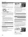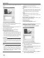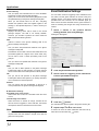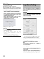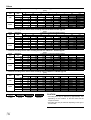
1
NETWORK VIDEO RECORDER
VR-N900U
INSTRUCTIONS
Powered by Milestone
Please read the following before getting started:
Thank you for purchasing this JVC product.
Before operating this unit, please read the instructions
carefully to ensure the best possible performance.
When this device is used as a general
household, there is a possibility of radio
disturbance to the radio and television
receiver etc.
For Customer Use:
Enter below the Serial No. which is located on the
body.
Retain this information for future reference.
Model No.
VR-N900U
Serial No.
LST0497-001A
Introduction
Hard Disk Drive
Consumable Item
The distance between the head and disk that read and write
data on the hard disk drive (hereinafter known as the HDD)
is a miniscule 0.02µm. Vibrations and physical shocks to the
HDD may therefore result in the head coming into contact
with the disk, producing dents and scratches to its surface.
This will consequently prevent data from being read, and will
result in disk crashes if use is continued. It is therefore
necessary to handle the recorder with great care.
■ The hard disk is a consumable item. Replacement is
recommended after 10000 hours of use (if use in a 25°C
environment). For information on maintenance planning
and costs, consult your nearest JVC dealer.
■ The fan motor is a consumable item. Replacement is
recommended after 30000 hours of use (if use in a 25°C
environment). For information on maintenance planning
and costs, consult your nearest JVC dealer.
■ Installation and Changing the Location of Installation
• Do not move the recorder or commence the installation
process when the power is turned on or immediately
after the power has been switched off (for approximately
one minute) under any circumstances. (The HDD will
continue to rotate due to inertia for a few moments after
the power has been switched off, and vibrations or
physical shocks will result in damage.)
• Wrap the recorder in protecting packing to prevent
physical shocks.
How to Read The Instructions
■ Handling
• Handle this equipment with care. Do not subject it to
physical shock.
• Do not unplug the power cord during recording or
playback, or when the HDD is being accessed.
■ It is recommended that an UPS (Uninterruptible
Power Supply) is used when installing additional
external hard disk drives to make sure the system
remains stable.
■ If a power failure occurs while using utilities,
operation of the equipment may be disabled even if it
is connected to the UPS.
■ About the VR-N900U document
The two documents shown below are available.
(1) STARTUP GUIDE
A STARTUP GUIDE booklet is bundled with VRN900U. Also, a STARTUP GUIDE is available as a
PDF file which is on the CD-ROM.
(2) INSTRUCTIONS (This PDF)
The INSTRUCTIONS is available as a PDF file which
is on the CD-ROM.
■ How to Read the Symbols
■ Please note that we will not provide compensation
for any failure during recording or playback due to
defects in this equipment or the hard disk drive.
CAUTION
Indicates points to note when operating the
recorder.
■ Please note that recorded images will be erased
when replacing hard disks. Note that there are cases
where recorded images may be erased when
software is upgraded.
Note
Indicates useful information, such
features and restrictions on use.
■ Use only hard disks recommended by JVC and use
only our service to replace hard disks.
Introduction
Introduction
☞
as
Indicates a reference page or reference
item.
■ Contents of this Manual
● The contents of this manual are the copyright of JVC.
They may not be reproduced in part or in whole
without the permission of JVC.
● All product names stated in this manual are
trademarks or registered trademarks of their
respective companies. Marks such as ™, ® and © are
omitted in this manual.
● Milestone and XProtect Enterprise are registered
trademarks of Milestone Systems.
● Designs, specifications and other contents of this
manual are subject to change without prior notice.
2
Contents
Playing Back Recorded Images..........................................16
Selecting a View..............................................................17
Searching for a Recorded Image ....................................17
Playing Back, Skipping and Stopping Recorded
Images ..............................................................................18
Introduction
Introduction........................................................................... 2
Adjusting the Playback Speed
(Jog/Shuttle Playback) .................................................20
Using Sequences ............................................................20
Preparation
System Connection Example .................................................... 5
Alphabet Input and Mouse Pointer.................................... 6
Entering Characters with the Software Keyboard
(Using a Mouse) ............................................................ 6
Operating the Mouse Pointer from the Front Panel
for Character Entry (without Using a Mouse)................. 6
Clock Display .................................................................... 7
About Performance Meter ................................................. 7
Changing monitor resolution ............................................. 7
Setting/Canceling Operation Lock ........................................ 7
Setting Operation Lock ..................................................... 7
Canceling Operation Lock................................................. 7
Displaying the Alerts List .................................................20
Audio ...............................................................................21
Smart Search ..................................................................21
Exporting Images and Audio ...........................................22
Printing the Recorded Images.........................................24
Recording Camera Images.................................................24
Recording Modes ............................................................24
Operations in Case of Power Failure ..............................25
Selecting the Record Control Mode ................................25
Selecting the Manual Recording Mode ...........................26
Specifying Recording Settings in Recording Control
Mode ............................................................................26
Specifying a Scheduler....................................................26
Camera Administration....................................................28
Setting the image quality .................................................29
Basic Operation
Screen Setup ......................................................................30
Switching the Power On/Off ................................................. 8
About Groups and Views.................................................30
Switching the Power On.................................................... 8
Creating Groups and Views ............................................30
Switching the Power Off.................................................... 8
Adding Cameras to a View..............................................32
Switching Operation On/Off by Pressing the Button
Adding Hot Spots (Enlarged Images) ................................ 32
on the Front Panel ............................................................ 8
Adding Carousels ............................................................33
Switching Operation On .................................................... 8
Adding Matrix Content.....................................................34
Switching Operation Off .................................................... 8
Using Static Images (GIF files, JPEG files, etc.) ............... 34
Switching Operation On/Off by the Rear
Using HTML Pages .........................................................35
Input/Output Terminals ...................................................... 9
Adjusting Camera Settings..............................................35
Switching Operation On .................................................... 9
Using Your Views on Different Computers.................................... 36
Switching Operation Off .................................................... 9
Customizing Joystick Setup ............................................37
Login..................................................................................... 9
Opening the Main Menu ..................................................... 10
Main Menu Contents ....................................................... 11
Using the VR-N900 Viewer ............................................. 11
Viewing Live Images........................................................... 12
Display the [Live Viewing] window .................................. 12
Selecting a View.............................................................. 12
Selecting a Camera ........................................................ 12
Using the PTZ Feature.................................................... 13
Using Preset Positions .................................................... 14
Other Useful Functions ................................................... 14
Applications
Camera Record Setting Window ........................................38
Display the [Camera Record Setting] window .................38
Adding Cameras .................................................................40
[Edit Device Settings] window .........................................41
[Camera Settings for Device Name] window...................42
Defining a PTZ Preset Position..................................................... 43
Pausing the Recording Server ........................................43
Display the [PTZ Preset Positions] window.....................43
3
Introduction
Defining a Preset Position............................................... 44
PTZ preset positions on events....................................... 45
Auto PTZ Patrolling ......................................................... 45
Camera Input/Output Port and Events ............................... 47
I/O Setup ........................................................................ 47
Configuring Event Buttons .............................................. 50
Specifying Generic Events .............................................. 51
Event Notification Settings .............................................. 52
Specifying an Output Port ............................................... 53
Output Settings for Cameras .......................................... 53
Motion Detection Settings .................................................. 54
You can configure the camera’s motion detection. ......... 54
Defining Exclusion Regions ............................................ 54
Other Settings .................................................................... 55
General Settings ............................................................. 55
Email Settings ................................................................. 56
Archiving ......................................................................... 57
Unit Setting ..................................................................... 58
OS Setting....................................................................... 59
Flash Memory Utility........................................................ 60
Auto Detect Setting ......................................................... 62
HDD Utility ...................................................................... 63
Language Setting ............................................................ 64
Image Server Setting.......................................................... 64
Connecting to a Computer ................................................. 67
System requirements ...................................................... 67
Computer Network Settings ............................................ 68
Installing the VR-N900 Viewer on Your Computer .......... 69
Log In to the VR-N900 Viewer ........................................ 71
Using the VR-N900 Viewer ............................................. 72
Log Out and Exit the VR-N900 Viewer............................ 72
Others
Compatible Equipment ....................................................... 73
Compatible Network Cameras ........................................ 73
Connecting a UPS .......................................................... 73
External Hard Disk Drives ............................................... 74
Recording Time Schedule............................................... 75
Default (Initial) Value List ................................................ 77
Troubleshooting.................................................................. 81
4
System Connection Example
Preparation
Analog cameras
Speaker (with built-in amplifier)
Microphone
VIDEO IN
1–4
VIDEO
IN
1–4
AUDIO OUT
AUDIO OUT
Alarm IN/OUT
AUDIO IN
ALARM IN/OUT
Mic Amp
REAR I/O Terminals
Supplied power cable
AC 120-240V 50Hz/60Hz
VGA OUT
LAN2
SERIAL
VGA monitor
Mouse
LAN1
IP cameras
Switching HUB
Switching HUB
Surveillance computer
SERIAL
UPS control
* You can connect up to 9 cameras (of
which up to 4 can be analog cameras).
* You can connect up to ten surveillance
computers.
* Reverse letters denote the terminals on
the rear panel.
Computer for configuring cameras
UPS
The following operations are possible with this system.
• Surveillance (live image recording/playback) by connecting
up to 9 cameras
• Checking recorded images on the VGA monitor
• Recording/playing sound
• Alarm recording
• Remote monitoring by computer
120V-240V
Note
• Connect LAN1 to the camera network.
• Connect LAN2 to the surveillance computer network.
• For details of the protocol and port number for the network
cameras on the LAN1 network, refer to the network
camera’s user manual.
• The protocol and port number used on the LAN2 network
are shown below.
Surveillance computer: HTTP 80
Email transmission:
SMTP 25
POP 110
5
Preparation
CAUTION
• Connect the IP camera after having turned off the system
and connected devices.
• Set the IP address of camera to 192.168.0.xxx. When
setting the IP address of camera other than
192.168.0.xxx, you must also change the IP address of
LAN1. As for the modification method of the camera’s IP
address, refer to the instruction manual of each camera.
• Do not connect LAN1 to the internet. If the internet is busy
or the relay equipment fails, you may not be able to save
important camera images. To maintain full recording
capacity, it is recommended that a dedicated network be
used. Be sure to connect the LAN1 camera network to the
same segment. (Do not use the address translation of
NAT and NAPT etc. or a router.)
• If you connect LAN2 to the internet from a surveillance
computer, you will need to configure IP Masquerading.
• Communication between LAN1 and LAN2 is not possible.
Nor is it possible to configure a camera connected to
LAN1 from the surveillance computer connected to LAN2.
In order to configure a camera connected to LAN1, it is
necessary to connect the computer for configuring
cameras to LAN1.
• LAN1 and LAN2 are incompatible with QoS. Sound may not
be played normally depending on the condition of the circuit.
• The default LAN1 IP address is 192.168.0.253 and the
default LAN2 IP address is 192.168.1.253. You can
change the address in the [OS Setting] window. ( ☞
Page 59) In the VR-N900U, analog input circuitry is
considered as a network encoder (IP video server) and
the IP address 192.168.201.12 is set by default. To
change the LAN1 or LAN2 IP address, specify an address
other than 192.168.201.0 - 192.168.201.255. Make sure
that you do not use the same segment in the LAN1 and
LAN2 addresses.
• If a single IP camera is registered to multiple VR-N900U
units, recording may not be carried out normally or
improper camera operations, such as PTZ control, may
result. It is recommended that a single IP camera is
registered and controlled for PTZ operations by a single
VR-N900U.
• Be sure not to connect a broken hub, router or
deteriorated network cable etc. The system may not
operate properly.
• It is not recommended to connect to a keyboard.
Alphabet Input and Mouse Pointer
You can enter letters of the alphabet and move the mouse
pointer using the buttons on the front panel, but it is easier
to make complicated settings and enter letters if you
connect a mouse.
• It is not recommended to connect to a keyboard.
6
Entering Characters with the Software
Keyboard (Using a Mouse)
You can use the software keyboard to enter letters of the
alphabet with the mouse.
1
Press the [KEY] button.
• The software keyboard will appear.
• Press the [KEY] button again to close the software
keyboard.
2
Move the mouse pointer over the letter on the
software keyboard that you want to enter.
3
Click the letter on the software keyboard that
you want to enter.
Note
• You can move the software keyboard by dragging any
portion of the keyboard other than the keys with the mouse.
• To drag the software keyboard from the front panel, press
the arrow buttons on the keypad while holding down the
[ZOOM IN/ENTER] button.
CAUTION
• You can move the cursor with the keypad when the
software keyboard is displayed.
• [ZOOM IN/ENTER] button is enabled with a click of a
mouse when the software keyboard is displayed.
• You cannot enter 2-byte character with the VR-N900U.
Operating the Mouse Pointer from
the Front Panel for Character Entry
(without Using a Mouse)
When a mouse is not connected, you can operate the
mouse pointer from the front panel.
1
Press the [KEY] button.
• The software keyboard will appear.
• Press the [KEY] button again to close the software
keyboard.
2
Move the mouse pointer with the keypad.
Pressing the [ZOOM IN/ENTER] button is the same as
clicking at the position of the mouse pointer.
Clock Display
Changing monitor resolution
The VR-N900U has a clock display function that displays the
current time on the screen.
Press the [ZOOM OUT/CANCEL] or the [ZOOM IN/ENTER]
button while holding down the [FUNCTION] button to
change VGA output resolution.
1
Press the [2/
] button while holding down the
[FUNCTION] button.
CAUTION
Clock display appears on the screen.
• Selecting a resolution not supported by the monitor may
prevent normal monitor synchronization.
Note
• To turn the clock display off, press the [2/ ] button again
while holding down the [FUNCTION] button.
• To move the clock display position, left click and drag the
clock display to the desired position.
About Performance Meter
The VR-N900U comes with a performance meter to indicate
VR-N900U operating load.
At high operating loads, the system may not be able to
record at the preset frame rate or operate normally.
1
Press the [1/
Setting/Canceling
Operation Lock
The VR-N900U is equipped with an operation lock feature is
to prevent the system from being placed into OPERATE
OFF accidentally and prevent unauthorized recording
operations.
Setting Operation Lock
1
[FUNCTION] button.
] button while holding down the
[FUNCTION] button.
A performance meter is displayed on the screen.
Load factor less than 5%
Indicated in gray
Press the [KEY] button while holding down the
Operation will be locked. The [LOCK] indicator lights up
when in operation lock mode.
Canceling Operation Lock
Load factor less than 60% Indicated in Green
Load factor less than 90% Indicated in Yellow
1
(When in operation lock mode) Press the [KEY]
button while holding down the [FUNCTION]
Load factor more than 90% Indicated in Red
Note
• The performance meter automatically displays when the
VR-N900U powers up.
• To turn the performance meter off, press the [1/ ] button
again while holding down the [FUNCTION] button.
• To move the display position of the performance meter,
left click and drag it to the desired position.
button.
Operation lock will be canceled. The [LOCK] indicator will
turn off.
Keypad
[LOCK] indicator
[KEY] button
[ZOOM IN/ENTER] button [FUNCTION] button
CAUTION
• Do not use the recorder when the performance meter is
indicated in red.
7
Basic Operation
Switching the Power On/Off
Switching Operation On/Off by
Pressing the Button on the Front Panel
Basic Operation
You are able to switch operation on or off.
Switching the Power On
1
Connect the power cable.
Connect using the power cable supplied to an AC 120V 240V 50Hz/60Hz outlet.
2
Turn on the power switch on the rear panel.
• A system check will run when the power is turned on.
• The [OPERATE] indicator will blink.
• After blinking, the [OPERATE] indicator will light up to
indicate that operation has been turned on.
• When the settings have been completed, recording
operation is started automatically with record control
mode.
Switching Operation On
1
(With operation off) Press the [OPERATE]
button.
• The [OPERATE] indicator will blink.
• The [OPERATE] indicator will light up, indicating that the
system is operable.
Note
• When the power switch on the rear panel is turned on, the
system starts up to initiate a system check until the
OPERATE ON mode is activated.
CAUTION
• Do not disconnect the power cord nor turn the power
switch off while the system check is running or in the
OPERATE ON mode as this may cause a malfunction.
Switching Operation Off
1
(With operation on) Press and hold the
[OPERATE] button for about 2 seconds.
Switching the Power Off
1
Press and hold the [OPERATE] button for
about 2 seconds to turn operation off.
After blinking, the [OPERATE] indicator will go off.
2
Turn off the power switch on the rear panel.
CAUTION
• The recorded images may not play back properly if they
were not archived ( ☞ Page 57) before the power failure.
• It is recommended that an uninterruptible power supply
(UPS) be used to protect the hard disk from damage in
the event of a power failure. ( ☞ Page 73)
8
• The [OPERATE] indicator will blink.
• The screen will go blank and the [OPERATE] indicator will
go off, indicating that operation has been turned off.
CAUTION
• Do not turn off the power until operation has been turned
off.
Switching Operation On/Off by
the Rear Input/Output Terminals
Login
• For details on the rear input and output terminal layout,
refer to “Rear I/O Terminals” (Page 9) in the STARTUP
GUIDE.
If [Auto Login] is set to [Off], the [Login] window will appear
after the system activates. Use the keypad to enter your
password and press the [ZOOM IN/ENTER] button.
Switching Operation On
Note
1
(With operation off status) Press the [OPE ON/
OFF] button.
• You can set [Auto Login] to [On] or [Off] from [Unit Setting]
in the Main Menu. ( ☞ Page 58)
• The [OPERATE] indicator will blink.
• The [OPERATE] indicator will light up, indicating that the
system is operable.
Switching Operation Off
1
(With operation on status) Hold down the [OPE
ON/OFF] button for approximately 2 seconds.
• The [OPERATE] indicator will blink.
• The screen will go blank and the [OPERATE] indicator will
go off, indicating that operation has been turned off.
CAUTION
• Do not turn off the power until operation has been turned
off.
[Login] window
9
Basic Operation
Opening the Main Menu
1
Press and hold the [REC/STOP] button for
more than 2 seconds.
Recording will stop.
• When in recording control mode, press and hold the [REC
CONTROL] button for more than 2 seconds to switch the
recording control mode off and stop recording.
• For details of recording mode, refer to “Recording Modes”.
( ☞ Page 24)
Wallpaper screen
When login has been successfully completed, the wallpaper
screen will appear.
• If you select [Live Viewing Auto Start] as the startup
window, the [Live Viewing] window is automatically
displayed after the login has been successfully completed.
2
Press the [REC CONTROL] button while
holding down the [FUNCTION] button.
• The Main Menu will appear. Select a menu with the [2/ ]
or [8/ ] button and press the [ZOOM IN/ENTER] button
to open the selected main menu.
• Same operation can be done with the [SKIP] button.
Note
• You can select [Live Viewing Auto Start] from the [Unit
Setting] in the Main Menu. ( ☞ Page 58)
zz_
Main Menu
Note
• Press the [ZOOM OUT/CANCEL] button to close the Main
Menu.
[Live Viewing] window
CAUTION
• When using the main menu display operation during the
VR-N900 Viewer startup, the VR-N900 Viewer may
display in rare cases. In this case, press the [LIVE/
BROWSE] button of the front panel and use the display
operation of the main menu again.
10
Main Menu Contents
Using the VR-N900 Viewer
The Main Menu contains the following menus. Select the
required item with the [2/ ] or [8/ ] button and specify the
settings. Press the [ZOOM IN/ENTER] button to save the
settings and press the [ZOOM OUT/CANCEL] button to
close the menu and return to the Main Menu.
You can view live and recorded images with the VR-N900
Viewer. You can also use the VR-N900 Viewer when
monitoring the VR-N900U from a surveillance computer.
( ☞ Page 71) Some of the VR-N900 Viewer functions differs
when remote monitoring from a PC.
• Unit Setting ( ☞ Page 58)
Lets you specify VR-N900U settings.
• OS Setting ( ☞ Page 59)
Lets you set the time, IP address and other OS settings.
• Flash Memory Utility ( ☞ Page 60)
Lets you copy the settings data to the flash memory, etc.
• HDD Utility ( ☞ Page 63)
Lets you check the status of the hard disk and format the
hard disk.
• Language Setting ( ☞ Page 64)
Lets you specify the language you want to use.
• Image Server Setting ( ☞ Page 64)
Displays the [Image Server Setting] window.
• Screen Setup ( ☞ Page 30)
Displays the [Screen Setup] window.
• Live Viewing ( ☞ Page 12)
Displays the [Live Viewing] window.
• Auto Detect Setting ( ☞ Page 62)
Lets you specify the IP lease settings and set up the
automatic camera detection feature.
• Camera Record Setting ( ☞ Page 38)
Displays the [Camera Record Setting] window.
• Exit
Exits the Main Menu.
[SELECT] button
[2/
] button
[FUNCTION] button
[8/
[ZOOM IN/ENTER] button
] button
[REC/STOP] button
Note
• The VR-N900 Viewer logs into the Image Server in the
VR-N900U for operation.
• The VR-N900 Viewer logs into the Image Server in the
VR-N900U (http://localhost or http://127.0.0.1). By default,
[Auto Login] to the VR-N900U is set to [On]. For details on
the log in, refer to “Log In to the VR-N900 Viewer”.
( ☞ Page 71)
• When the maximum number of clients are connected to
the surveillance computer, the VR-N900 Viewer cannot
log in.
CAUTION
• When you have changed in each setting of the [Camera
Record Setting], log out the VR-N900 Viewer ( ☞ Page
72) first, then log in to the VR-N900 Viewer again.
• You can log in to the VR-N900 Viewer by clicking the
[Connect] button in [Connect to Server] window with the
default position. If the setting has been changed, please
refer to step 2 of the [Log In to the VR-N900 Viewer]
instructions ( ☞ Page 71).
• When the VR-N900 Viewer has become as described
below, the following conditions may be recoverable by
restarting the VR-N900 Viewer.
- Live Images and Playback Images are all black.
- VR-N900 Viewer operation is slow.
- VR-N900 Viewer does not respond.
• When restarting VR-N900 Viewer, press the [ALARM
CLEAR] and [SELECT] buttons while holding down the
[FUNCTION] button.
[ZOOM OUT/CANCEL] button
[REC CONTROL] button
[SELECT] button
[ALARM CLEAR] button
[FUNCTION] button
• With the VR-N900 Viewer, the image and sound may not
properly synchronize when played back.
• When setting the E-mail ( ☞ Page 56), test and verify that
E-mail is sent.
• When an external hard disk is connected, it may take
several minutes for the startup.
11
Basic Operation
Viewing Live Images
Selecting a View
For details of creating views, refer to “Screen Setup”.
( ☞ Page 30)
1
Display the [Live Viewing] window
1
Press the [LIVE/BROWSE] button or select
[Live Viewing] in the Main Menu.
• The VR-N900 Viewer starts up and the [Live Viewing]
window appears.
• If the setup window is displayed, close the setup window.
• If the [Browse] window is displayed, press the [LIVE/
BROWSE] button.
• The window switches between the [Live Viewing] window
and the [Browse] window each time the [Live Browse]
button is pressed.
• You can also click the [Live] tab with the mouse.
• To close the [VR-N900 Viewer] window, click the [Close]
button.
[Live] tab
[Views] section
[View] list
[Close] button
Press the [PTZ/PRESET] button until the [PTZ/
PRESET] indicator blinks.
The [PTZ/PRESET] indicator switches between lit and
blinking each time the [PTZ/PRESET] button is pressed.
2
Press the [ZOOM IN/ENTER] or [ZOOM OUT/
CANCEL] button to select a view.
Note
If you connect a mouse, you are able to select a view in two
ways:
• By selecting the required view in the [Views] section.
• By selecting the required view from the [Views] list located
in the upper part of the window.
CAUTION
• Make sure not to set the changeover of the view with short
intervals.
• When live image is not displayed with VN-C625/VN-C655,
reset the password of the camera and VR-N900U. As for
setting method, refer to the Instruction Manual that came
with the camera and setting method of the root password of
the [Edit Device Setting] window of this book ( ☞ Page 41).
• When returning from a [Setup] window to [Live], the audio
settings becomes [None]. Please set the audio again.
Selecting a Camera
1
Press the [SELECT] button to set the keypad to
selection mode.
[Live Viewing] window
• If you enter settings in the [Camera Record Setting]
window without closing the [Live Viewing] window, live
images may not appear immediately after the camera
settings have been completed. In this case, [Unable to
connect to the server! Reconnecting to the server] or
[Unable to connect to 127.0.0.1:80 on the device name
(camera name)! Reconnecting to the server] appears on
the [Live Viewing] window (127.0.0.1:80 is an internal IP
address of the VR-N900U).
Note
• Depending on the condition of the network circuit, it may
take some time until images from the camera are
displayed.
• Depending on the connection of the additional hard disk,
several minutes may be required for the [Live Viewing]
window to display.
12
The [SELECT] indicator will light up.
2
Enter the camera number with the keypad.
• If you press the same camera number twice, images from the
camera will be enlarged.
• To return to normal view, press the same camera number
once more.
• If you press a different camera number while images are
enlarged in the view, live images from the selected
camera will be enlarged. The multiple screen display may
briefly appear when camera selection is changed in
enlarged view.
• You can also click the bar at the top of the live image of a
particular camera with the mouse to select the image.
• You can change the camera number in the [Record
Camera Setting] window. ( ☞ Page 38) If you press 0 first
and then enter the camera number, you can specify
numbers from 10 to 19. Use the mouse to specify
numbers from 20 upwards.
Note
• When you select a particular camera, the blue bar at the
top of each live image becomes a lighter blue.
Each bar features three-color square indicators with the
following functions.
➀ Event indicator (left indicator: solid yellow)
Lights up when events specified in the [Camera Record
Setting] occur. ( ☞ Page 52) Click the image bar to
reset the event indicator. The indicator appears black if
event indication has not been specified for the camera in
question, or if no specified events have occurred.
➁ Motion indicator (indicator in the middle, solid red)
Lights up when motion is detected. ( ☞ Page 54) Click
the image bar to reset the event indicator.
➂ Online indicator (right indicator, blinking green)
Blinks every time an image is received from the
camera.
• The image bar displays the name of the camera as well as
the name of the device to which the camera is connected.
• Each image bar will display the word [Live] when live
images are displayed, and the word [Stopped] if the
camera is stopped and live viewing is not possible.
• To enlarge images from a particular camera in a view
using a mouse, double-click the image bar. To return to
normal view, simply double-click the image bar again.
• The event or motion indicator can also be canceled by
pressing the [ALARM CLEAR)] button.
[Output] section
[Event] section
[Live Viewing] window
[PTZ Control] section
[Audio] section
➀
➁
➂
Using the PTZ Feature
PTZ stands for pan, tilt and zoom. If the camera is a PTZ
camera, you can use the keypad and the [ZOOM IN/
ENTER] button and [ZOOM OUT/CANCEL] button to move
the camera up, down (tilt), right and left (pan) and enlarge
the image (zoom).
Pan/Tilt
1
Press the [PTZ/PRESET] button until the [PTZ/
PRESET] indicator lights up.
The [PTZ/PRESET] indicator switches between lit and
blinking each time the [PTZ/PRESET] button is pressed.
2
Press the arrow buttons on the keypad to
move the camera in the selected direction.
• Pressing the [HOME] (default) button on the keypad
moves the camera to its home position.
Zoom In/Zoom Out
1
Press the [PTZ/PRESET] button until the [PTZ/
PRESET] indicator lights up.
The [PTZ/PRESET] indicator switches between lit and
blinking each time the [PTZ/PRESET] button is pressed.
2
Press the [ZOOM IN/ENTER] button or the
[ZOOM OUT/CANCEL] button.
CAUTION
• The PTZ features are only available if the camera is a
PTZ camera. If the camera is not a PTZ camera, pressing
the button will have no effect.
Note
• Many PTZ cameras may be controlled by pointing and
clicking inside the images from the camera. If you see a
set of crosshairs when placing your mouse pointer over
the images from a PTZ camera, point-and-click control is
supported for the camera.
• The camera cannot be operated in the [Image] window
when the mouse pointer does not change to the cross
shape pointer.
• The mouse pointer may not change to the cross-shape
pointer depending on the type of the PTZ camera.
• The PTZ camera may not operate even though mouse
pointer changed to the cross-shape pointer depending on
the PTZ camera. In this case, use the PTZ navigation
button of the [PTZ control] section to operate the PTZ
camera.
• For PTZ cameras, if your mouse is equipped with a scroll
wheel, you are able to zoom in and out using the scroll
wheel on your mouse.
13
Basic Operation
• You are able to use the PTZ Navigation buttons in the
[PTZ Control] section to move the selected PTZ camera.
The round middle button lets you quickly move the
camera to its home position. The [+] and [-] buttons lets
you zoom in and out respectively.
CAUTION
• The buttons are only available if the camera is a PTZ
camera.
[LIVE/BROWSE] button and indicator
[SELECT] button and indicator
Keypad
Digital Zoom
By selecting the [PTZ Control]’s [Digital Zoom] check box,
you are able to use digital zoom on images from any camera
displayed in the view. When digital zoom is enabled, you will
see a small overview frame in the bottom right corner of
each of the view’s camera positions.
[PTZ Control] section
[PTZ Navigation] button
[ZOOM IN/ENTER] button
[ZOOM OUT/CANCEL] button
[PTZ/PRESET] button and indicator
Other Useful Functions
●Audio
[Digital zoom] check box
[Live Viewing] window
Note
To listen to live audio, select the required audio source in the
[Audio] section’s [Audio Sources] list.
To temporarily mute the live audio, select the [Mute] check
box.
• The recorded image(s) will not be recorded in zoom even
when the digital zoom is used.
• When the digital zoom is used, the recording frame rate may
decrease because the load factor of VR-N900U becomes
high.
• To exit the digital zoom, unselect the [Digital Zoom] check box
or click the [-] button until the image returns to normal size.
[Live Viewing] window
Using Preset Positions
This feature lets you move the camera to preset positions by
entering the preset number with the keypad. ( ☞ Page 44
“Defining a Preset Position”)
1
Press the [PTZ/PRESET] button until the [PTZ/
PRESET] indicator blinks.
The [PTZ/PRESET] indicator switches between lit and
blinking each time the [PTZ/PRESET] button is pressed.
2
Move the camera to a preset position by
entering the preset number with the keypad.
• If you press 0 first and then enter the preset number, you
can specify numbers from 10 to 19.
• To specify numbers from 20 upwards, select the preset
number from the [Presets] list in the [PTZ Control] section
with the mouse.
14
CAUTION
• When the audio source is selected on multiple surveillance
computers, sound quality may deteriorate.
• When returning from a [Setup] window to [Live], the audio
settings becomes [None]. Please set the audio settings
again.
Note
• When you select a camera which had the audio source
set by the [Camera Setting] of [Camera Record Setting]
window, the specified audio is output. ( ☞ Page 28)
• Selecting a camera not set to record an audio will output
the most recently selected audio source continuously.
• When you select a camera that has not set an audio
source, the most recently played audio will output
continuously.
• When the recording and live image is simultaneously
displayed, the displayed video and audio may not properly
synchronize. (There is no effect to the recording in the
system or the additional hard disk.)
●How to Manually Trigger an Event
●Camera Shortcut Menus
To manually trigger an event, select the required event in the
[Event] section, and click the [Activate] button.
By right-clicking inside one of the images from the camera,
you get access to a shortcut menu.
Some of the shortcut menu’s content may vary from camera to
camera, depending on the configuration of the selected camera.
[Event] section
[Live Viewing] window
Note
• For details of events, refer to “Camera Input/Output Port
and Events”. ( ☞ Page 47)
• Events must be defined in advance. ( ☞ Page 47)
●Outputs
To trigger an output, select the required output in the
[Output] section, and click the [Activate] button.
Camera:
Lets you select another camera image for display in the
view position.
Sound Notifications:
Lets you temporarily mute sound notifications.
PTZ Presets:
Lets you select between the camera’s preset positions.
Matrix:
Select this option to use the Milestone XProtect Matrix
feature. For details, refer to the Milestone XProtect Matrix
manual provided by Milestone Systems.
Send Camera:
Lets you send images from the selected camera to
another single-camera position in an open view.
[Output] section
[Live Viewing] window
Note
• Output must be defined first. ( ☞ “Specify an output” on
Page 49)
15
Basic Operation
Playing
Images
Back
Recorded
[Views] section
[Close] button
CAUTION
• The recording frame rate may decline when using the
[Live Viewing] window.
• For the area(s) that do not support the Daylight Saving Time
(DST). If DST is entered, the sections where a change to
DST is made may not be properly played back or searched.
• When the recording and recorded image is simultaneously
played back, and access to the hard disk occurs
frequently, the image which is played back may pause and
the audio may break up. (There is no effect to the
recording in the system or the additional hard disk.)
• When returning from the [Setup] window to the [Browse]
window, the audio settings becomes [NONE]. Please
select the audio source again.
●Display the [Browse] window
1
Press the [LIVE/BROWSE] button or select
[Live Viewing] from the Main Menu.
The VR-N900 Viewer starts up and the [Live Viewing] window appears.
2
When the [Live Viewing] window appears, press
the [LIVE/BROWSE] button again.
The window switches between the [Live Viewing] window
and the [Browse] window each time the button is pressed.
[Browse] window
[Sequences] section
[Alerts] section
[Time navigation] section
[Audio] section
[Smart Search] section
[Export] section
• It may take a few minutes until the [Browse] window is
displayed.
• If you enter settings in the [Camera Record Setting]
window without closing the [Browse] window, recorded
images may not be displayed immediately after the
camera settings have been completed. In this case,
[Unable to connect to the server! Reconnecting to the
server] or [Unable to connect to 127.0.0.1:80 on the
device name (camera name)! Reconnecting to the server]
appears on the [Browse] window (127.0.0.1:80 is an IP
address of the VR-N900U).
• If you play back a recorded image that is not recorded at
all, [Connection: [N900] Camera1 on 127.0.0.1:80] will
display continuously in the [Browse] window.
• To close the VR-N900 Viewer, click the [Close] button.
Note
[Live Viewing] window
• You can also click the [Browse] tab with the mouse.
• Each image bar features an online indicator, which is
useful when browsing the recordings. The indicator lights
up green each time a new image is displayed.
• Recorded images are saved as a database. Recorded
image data is called the database in this device.
• When [Before Database Start] appears on the [Browse]
window, no database (recorded image) exists in prior to
the current image viewed.
• When [After Database End] appears on the [Browse]
window, no database (recorded image) exists after the
current image viewed.
• Make sure not to set the changeover of the Live and
Browse at short intervals.
CAUTION
• If several sections are opened in the left side of the [Live
Viewing] window, it may not be possible to display them all
in the window. If this happens, double-click the section
bars and close the sections.
16
Selecting a View
The specified date and time will appear in the [Master Time]
area.
1
Note
Press the [PTZ/PRESET] button until the [PTZ/
PRESET] indicator blinks.
2
Press the [ZOOM IN/ENTER] or [ZOOM OUT/
CANCEL] button to select a view.
Note
If you connect a mouse, you are able to select a view in two
ways:
• By selecting the required view in the [Views] section.
• By selecting the required view from the [Views] list located
in the upper part of the window.
• The [Master Time] area displays the recording date and
time of the selected playback images. The master time is
the time to which all the cameras are linked, and when
you specify a time, all the images you see in the [View]
will be from exactly the same point in time.
• Some cameras may only record if motion is detected. Also,
there may be no recorded images from one or more
cameras in the view matching the specified point in time.
When this is the case, the last image in the camera’s
database prior to the specified point in time will be displayed
in the view. (Recorded images are saved to the database.)
• The [Master Time] area also displays the current selected
playback speed.
Searching for a Recorded Image
[Time Navigation] bar
You can search for and play back images by specifying a
date and time.
[Master Time] area
●Using the [SEARCH] button on the front panel
1
Click the [SEARCH] button in the [Browse]
window.
The date and time input window will appear.
[Browse] window
[Go To] button
[Time Navigation] section
CAUTION
[Date and time input] window
2
Use the keypad to enter the search date and time.
Select the entry field with the [SKIP] button (7 or 6) and
input the date and time.
3
Press the [ZOOM IN/ENTER] button.
The view in the image display window on the right will jump
to the selected date and time.
●Using the mouse
• The [Master Time] area may display an exceeded record
date and time of the latest recorded image. In this case,
click the
button and move to the latest recorded
image, and then click the
button.
• When [Skip gaps during playback] is selected in the [Time
Navigation] section, playback may stop when it exceeds
the end of the recording while recording and playback
simultaneously. In this case, deselect the [Skip gaps
during playback] checkbox. If the playback stops, please
click the play button again.
Use [Time Navigation] section in the [Browse] window.
1
Double-click the [Time Navigation] bar in the
[Browse] window.
2
Enter the search date and time in the boxes on
the left of the [Go To] button at the bottom of
the window.
Specify the date in the left-hand box and the time in the
right-hand box.
3
Click the [Go To] button.
The view in the image display window on the right will jump to
the specified date and time.
17
Basic Operation
●Using the [Timeline Browser]
You can browse through recorded images using the
[Timeline Browser] on the right of the [Browse] window. The
vertically extended timeline shows the recording status and
reflects only the number of cameras displayed in the
VR-N900 Viewer. Drag on the timeline up or down with the
mouse while checking the time display pointer.
• The timeline is only a rough guide and may differ from
actual time.
• When you do not need the timeline browser, you can hide
it by clicking the [Display ON/OFF] button in the left side of
the timeline browser’s border.
CAUTION
• If you drag on the timeline suddenly up or down with the
mouse, a portion of the timeline may not update. In this
case, reboot the VR-N900 Viewer ( ☞ Page 11).
Playing Back, Skipping and Stopping
Recorded Images
Timeline
●Using the [PLAY], [SKIP] and [STOP(PB)] buttons
on the front panel
Playing Back
Time display pointer
1
Press the [PLAY] button.
• Playback will start from the date and time displayed in the
[Master Time] area of the [Time Navigation] window.
• Images will be played back according to the angle of the
shuttle dial. (x1/20, x1/5, x1, x2, x5, x10, x20)
[Display ON/OFF]
button
Skipping
1
[Timeline browser]
●Timeline Colors and Lines
The timeline of the camera selected in the view is
highlighted in a lighter color.
■ Red: Recordings with motion
(Pink when highlighted)
■ Green: Recordings without motion
(Light green when highlighted)
■ Black: Periods without recordings
(Gray when highlighted)
■ White horizontal line (Time display pointer): Indicates the
time recorded for the image being displayed
Note
• Immediately below the timeline browser itself, you are able to
specify which time span (1 hour, 2 hours, etc. up to 1 day)
should be used in the timeline, and these settings are not
saved and will be lost when the VR-N900 Viewer is restarted.
• If your mouse has a scroll wheel, you can also use the
scroll wheel for browsing the timelines.
• Double-click at any point within a timeline to quickly move
to the desired point in time.
18
Press the [SKIP] button.
The [SKIP] buttons have the following functions.
6: Moves to the first image in the previous sequence.
When pressed and held down, moves to the first
image in the database for the selected camera.
7: Moves to the first image in the next sequence.
When pressed and held down, moves to the latest
image in the database for the selected camera.
Note
• Sequences refers to sequences of images recorded when
an event or motion is detected.
• The recorded images are saved as a database.
CAUTION
• The [SKIP] button will not work when no camera is
selected.
• In simultaneous recording and playback, an [After
Database End] message may appear as playback catches
up with recording during playback near the current time.
• When motion/event is set to record ( ☞ Page 28), VRN900U will not record if the motion/event does not occur.
But when you playback near the current time, the image
which is not recorded will also playback.
Stopping
Time Slider
1
Moving the slider to the left changes the recording date to an
older date and moving the slider to the right changes it to a
more recent date. Use the top bar for fine browsing (x0.4 to
x240) within a limited period of time and use the bottom bar
for easy browsing (x20 to x36,000) for longer time spans.
Press the [STOP(PB)] button.
Playback will stop.
●Playing back, stopping and skipping using the mouse
[Master Time] area
Browse buttons
Playback Slider
The middle position is for playback at normal speed (1.00x).
Move the slider to the left to reduce the playback speed and
move it to the right to increase the playback speed.
Dragging the slider to its leftmost position pauses playback.
The playback speed is displayed at the top right of the
[Master Time] area.
[Browse] window
Play Buttons
Time Slider
: Plays back images in reverse.
Playback Slider
Play buttons
: Plays back images.
The buttons and sliders have the following functions.
Browse Buttons
Moves to the previous image of the selected
: camera (frame-by-frame playback in reverse
mode).
:
:
:
:
:
Moves to the next image of the selected camera
(frame-by-frame playback in forward mode).
Moves to the first image in the previous sequence
of the selected camera (This function does not
work properly if there are no sequences or with
some sequence lengths.).
Moves to the first image in the next sequence of
the selected camera (This function does not work
properly if there are no sequences or with some
sequence lengths.).
Moves to the image recorded on the most
previous date in the database for the selected
camera (This function may not work properly at
10x or higher playback speeds.).
Moves to the image recorded on the most
recent date in the database for the selected
camera (This function may not work properly at
10x or higher playback speeds.).
CAUTION
• The browse buttons are only enabled when a camera has
been selected.
• Time may be required for the images to be moved after
clicking the “previous sequence/next sequence” button.
Please note that if the buttons are clicked continuously
before the images are moved, the images will be moved in
the selected sequence collectively.
: Stops playback.
CAUTION
• The [Play] buttons do not work while the Playback Slider
is placed in its leftmost position (pause). Select the
desired speed by moving the Playback Slider.
• The angle of the shuttle dial does not affect playback, which
is operated in the [Time Navigation] section using a mouse.
Note
• If the [Skip gaps during playback] check box in the [Time
Navigation] window is selected, sections where there are no
recorded images from the selected camera will be skipped.
• When the recorded images are played back with some
images skipped, [SKIP] is displayed in red in the [Master
Time] area for a limited time.
• During playback, skip operations may differ between a
single screen and multiple screens. Even if the selected
camera has not made a recording, skipping will not take
place as long as another camera has made a recording.
The last recorded image appears in place of any section
that is not recorded.
[LIVE/BROWSE] button and indicator
[STOP(PB)] button
Keypad
[SEARCH] button
[PLAY] button [SKIP] button
[ZOOM IN/ENTER] button
[ZOOM OUT/CANCEL] button
[PTZ/PRESET] button and indicator
19
Basic Operation
Adjusting the Playback Speed (Jog/
Shuttle Playback)
Sequence
[Sequence] bar
You can adjust the playback speed by turning the jog dial/
shuttle dial on the front panel.
Shuttle Playback
• Rotate the shuttle dial during playback or when playback is
paused to start fast forward, fast reverse or slow playback.
Still
x1/20
x1/20
x1/5
x1/5
REV
Shuttle dial (Outside)
FF
x1
x1
x2
x2
x5
x5
x10
x10
x20
x20
Jog dial (Inside)
Jog/Shuttle dial
■ The playback speed indications when performing fast
forward or fast reverse playback by rotating the shuttle
dial are approximate. The speed may differ depending on
the conditions, such as the playback mode (multi-view,
single view) and the recording mode (motion detection,
recorded frame rate).
2
[Browse] window
Click the [Get Sequences] button.
• A list of 20 sequences prior to and following the point in
time displayed in the view will appear.
• If the [Preview] check box is selected, you are able to
quickly view each sequence by placing the mouse pointer
over the required sequence in the list.
3
Click a sequence in the list.
All images in the view move to the time of the sequence.
Note
• Clicking the expand icon (+) next to a sequence in the list
will show you the exact date and time of the first and last
image in the sequence as well as the exact date and time
of the motion detection, event, etc. triggering the recording.
Jog Playback
• Rotate the jog dial to play back frame-by-frame.
• Rotate the dial clockwise to play back a single frame in
the forward direction, and rotate the dial counterclockwise
to play back a single frame in the reverse direction.
• Release the dial to pause the playback. However, when
frames are played back successively in the forward or
reverse direction, playback may continue momentarily
after the jog dial is released.
CAUTION
CAUTION
The [Alerts] section lets you view a list of recorded images for
each alert, such as when motion is detected. ( ☞ Page 54)
• The jog dial will not work when no camera is selected.
• When the playback speed is modified or playing back at high
speed while recording, the frame rate of the recording may
decrease. Observe the performance meter while adjusting
the playback speed.
• There are times when the continuous multiple sequences
change into one sequence depending on [Pre/post
recordings on motion/event] setting. ( ☞ Page 29)
Displaying the Alerts List
1
Double-click the [Alerts] bar in the [Browse] window.
2
Click the [
] of the Alerts list and select the
required event or events in the Alerts list.
You may select either a single event or all events on a
camera/particular server.
Using Sequences
[Alerts] list
[Alerts] bar
Sequences refers to sequences of images recorded when
an event or motion is detected. You can refer to the list of
recorded images for each sequence.
1
Double-click the [Sequences] bar in the
[Browse] window.
[Browse] window
Events list
3
Click the [Get List] button.
This will display a list of detected events.
20
You are able to click the listed events to view recordings
from the required event in the view.
Note
• The Alerts list displays events occurring in the time period
(approx. 1 day before and after) set in [Time navigation].
Smart Search
Smart Search lets you specify motion in one or more
selected areas of images from a particular camera.
( ☞ Page 54)
1
Double-click the [Smart Search] bar in the
[Browse] window.
Audio
[Smart Search] bar
To listen to recorded audio, select the required audio source
in the [Audio] section’s [Audio Sources] list.
To temporarily mute the recorded audio, select the [Mute]
check box.
[Audio] section
[Browse] window
2
Select [Show Grid] check box in the [Search Area].
CAUTION
3
Select the required camera.
• The sound may become distorted when audio is played
back with multiple surveillance computers.
• When returning from the [Setup] window to the [Live]
window or [Browse] window, the audio settings becomes
[NONE]. To listen to an audio, reselect an audio from the
[Audio Sources] list.
• The audio will not be outputted at the time of still image
playback and search/frame advance playback other than
feed-forward x1.
• When a recorded image is played back while recording,
the played back audio may break up. (Recording)
A blue grid overlay will appear on the image.
[Browse] window
Note
• When you select an IP camera that has been set to record
an audio, the specified audio will output.
• Selecting a camera not set to record an audio will output
the most recently played back audio continuously.
• When the recording and recorded image is simultaneously
played back, the image which is played back may pause
and the sound may break up. (There is no effect to the
recording in the system or the additional hard disk.)
4
Click and drag inside the image to select the area
in which you want to perform the Smart Search.
• The areas you select will become visible through the blue
overlay.
• With the [Include] and [Exclude] options, you are able to
toggle between including/excluding areas when you drag.
With the [Invert] button, you are able to quickly invert your
selection.
5
In the [Search Setup] section, select the
required search sensitivity (Very Low - Very
High) in the Sensitivity list.
6
Select the required image interval in the
[Interval] list.
21
Basic Operation
7
Click the [Next] or [Previous] button to search
Select the required camera from the Source
through data with motion detected in the
list and click the [AVI/JPEG Export] button or
selected areas.
[Database Export] button.
The Smart Search will begin. When motion is detected
inside the selected area(s), it will be highlighted in the view.
CAUTION
• Smart Search is carried out forwards or backwards from
the time of the image you are viewing.
• A Smart Search performed during recording may lower
the recording frame rate. Observe the performance meter
and use the recorder in the range that does not indicate in
red.
8
4
• If you selected a source, you may select [Current View
Source], in which case the export will include images from
all cameras in the current view.
• This will open the export dialog. The export dialog will list
the specified start time, end time and camera.
• Export preparation may take some time depending on
how the external hard disk drive is connected.
5
If you selected [AVI/JPEG Export], select the
required export format.
Click the [Next] or [Previous] button to
continue the smart search.
Note
• You can use the [Save] button to temporarily save the
area you selected in step 4.
To return to the saved area settings, click the [Load]
button after you have finished selecting the required
areas.
• To cancel selection of an area, select the [Exclude] check
box, click and drag all the areas.
Exporting Images and Audio
1
Double-click the [Export] bar in the [Browse]
window.
• Select [AVI] (movie clip) or [JPEG] (still images).
• Select whether to add time stamps to the exported
images.
6
If you selected [AVI] format, select the required
frame rate.
[Export] bar
With the [Full] option, all images will be sent to the AVI file;
with the [Half] option, only every second image will be sent,
to reduce the size of the AVI file, though images will still play
back in real-time.
7
If you selected [AVI] format, select the required
[AVI Codec] in the [AVI Codec list] and enter
[Browse] window
2
Enter the export period start date and time.
Clicking the [Set] button sets the date and time of the
[Master Time] Area.
3
Enter the end date and time.
Clicking the [Set] button sets the date and time of the
[Master Time] Area.
22
the file name.
By default, the file name will have the structure [yyyymmddhhmmss.avi].
8
If you selected database format, the following
items can be specified.
11 If you selected database format, you are able to
Include Audio:
Select this check box to include audio in the export (if no
audio sources are attached, the check box will not be
available).
Compress Exported Database:
Select this check box to compress the exported database.
Encrypt Exported Database:
Select this check box to encrypt the exported database.
Specify a password for subsequent decryption.
9
Insert a USB memory device.
Insert the USB memory device you want to export the data to.
include a stand-alone version of the Viewer
(application
for
viewing
and
navigating
recordings) in the database export by selecting
the [Include Viewer Program Files] check box.
• To view the exported data on a PC, double-click the
[Browser.exe] file in the [Exported Images] folder of the
USB memory used for the [Export]. It will open the Viewer
and you can view the exported data.
12 Click the [Export] button.
Export will begin.
10 Specify the export destination.
Note
Desktop:
• Never select this with the VR-N900U.
• Select this when exporting with a surveillance computer
onto the desktop.
Path:
Select this with the VR-N900U.
Do not manually enter the path on the VR-N900U.
• For details on the Viewer, refer to the XProtect™
Enterprise 6.0 Monitor & Viewer User’s Manual provided
by Milestone Systems (http://milestonesys.com/?cid=265).
• To include audio within the export file with the AVI export
option, open the recorded image that has been exported
in the DB format on the Viewer and re-export it with the
AVI format on the Viewer again.
CAUTION
• When exporting with the database format, you are able to
include audio within the export file; with the AVI/JPEG
export option, you are not.
• The recording frame rate may decline during export.
• This recorder does not support Daylight Saving Time
(DST). If DST is set, the sections where a change to DST
is made may not be properly exported.
Select [Path] and select [C:\] to highlight, and then press the
[9] button of the keypad while holding down the
[FUNCTION] button on the front panel to automatically enter
the path of the USB memory.
23
Basic Operation
Printing the Recorded Images
Recording Camera Images
You may print the playback image that is displayed.
CAUTION
• This function is not available with the VR-N900U.
• This function is for the downloaded VR-N900 Viewer.
1
Double click the [Print] bar in the [Browse] window.
[Browse] window
2
Recording Modes
●Recording Control Mode
In this mode, recording is carried out in accordance with the
[Camera Record Setting].
The [REC CONTROL] indicator is lit.
You are able to switch the recording control mode on or off
by pressing and holding the [REC CONTROL] button.
• Set online/offline periods for each camera with the
[Scheduler] settings. ( ☞ Page 26)
• Specify the frame rate and conditions for starting
recording in [Camera Settings]. ( ☞ Page 28)
Click the [Print…] button in the [Print] section.
CAUTION
[VR-N900 Viewer Surveillance Report] window is
• The camera will not record during the offline periods
specified in the [Scheduler] settings, regardless of the
[Camera Settings].
• The [REC CONTROL] button is disabled when the Main
Menu is displayed, when settings are being specified and
during recording.
• When there is an unconnected camera, time may be
required for the [REC CONTROL] indicator lamp to light up.
displayed.
Note
• Press the [REC/STOP] button to cancel recording control
mode and enable manual recording mode.
• Press and hold down the [REC/STOP] button to cancel all
recording modes and stop recording.
• Set [Operate] to ON to automatically enter the recording
control mode.
●Manual Recording Mode
3
Click the [Page Setup] button in the [VR-N900U
Surveillance Report] window to set the printer.
4
Click the [Print] button to start printing.
When the printing ends, click the [Close] button to close the
print window.
Comments entered in [User’s Note:] are printed.
Manual recording is a recording mode that executes
recording from all cameras regardless of the settings in the
[Camera Record Setting]. It will be recorded at the frame
rate that was set in [Image Storage settings] - [Desired
framerate settings] of the [Camera Settings] window.
Manual recording lets you start and stop recording from all
cameras by pressing the [REC/STOP] button. Press the
[REC/STOP] button to start recording and press and hold it
down to end recording. Holding down the [REC/STOP]
button when recording is not on will not start recording.
The [REC CONTROL] indicator is off.
●Recording by EXT REC IN Signal Mode
Recording will start from all cameras when the [EXT REC
IN] terminal on the rear panel is set to MAKE state. It will be
recorded at the frame rate that was set in [Image Storage
settings] - [Desired framerate settings] of the [Camera
Settings] window.
24
Recording by EXT REC IN signal has priority over recording
control mode or manual recording.
When recording by EXT REC IN signal is finished, the
cameras will return to the original recording mode.
Note
• The [REC CONTROL] indicator goes off and the [REC]
indicator blinks during recording by EXT REC IN signal.
• Recording will start or stop from all cameras, regardless of
the [Scheduler] settings or [Camera Settings].
• Press the [REC/STOP] button to cancel recording by EXT
REC IN signal and enable manual recording mode. The
[REC] indicator that has been blinking lights up.
• Press and hold down the [REC/STOP] button to cancel
recording by EXT REC IN signal and stop recording.
●Emergency Recording Mode
Recording will start from all cameras when a MAKE signal is
detected by the [EMERGENCY] terminal on the rear panel.
It will be recorded at the frame rate that was set in [Image
Storage settings] - [Desired framerate settings] of the
[Camera Settings] window.
Recording will continue for the length of time specified in
[Emergency Record] in [Unit Setting]. ( ☞ Page 58)
Emergency recording has priority over recording control
mode or manual recording mode.
When emergency recording is finished, the cameras will
return to the original recording mode.
Note
• The [REC CONTROL] indicator goes off and the [REC]
indicator blinks during emergency recording.
• Recording will start and stop from all cameras, regardless
of the [Scheduler] settings or [Camera Settings].
• Press the [REC/STOP] button to cancel emergency
recording and enable manual recording. The [REC]
indicator that has been blinking lights up.
• Press and hold down the [REC/STOP] button to cancel all
recording modes and stop recording.
Operations in Case of Power Failure
If a power failure occurs during recording, the system will
perform recovery recording in the mode selected before the
power failure.
• In the [REC CONTROL] mode, recording by a motion or
event will not resume unless another motion or event is
generated after the power failure is recovered.
• The recording control mode returns to the status it had
prior to the power failure.
CAUTION
• The recorded images may not play back properly if they
were not archived ( ☞ Page 57) before the power failure.
• It is recommended that an uninterruptible power supply
(UPS) be used to protect the hard disk from damage in
the event of a power failure. ( ☞ Page 73)
• When a power failure occurs while formatting a hard disk
or archiving, even when an UPS is connected,
subsequent operations may be interrupted.
Selecting the Record Control Mode
1
Press and hold down the [REC CONTROL] button
while recording is stopped ([REC] indicator is off).
The [REC] indicator lights up and the unit will enter the [REC
CONTROL] mode. Recording will start in accordance with
the settings in the [Camera Record Setting].
• To stop recording, press and hold down the [REC/STOP]
button during recording other than [REC CONTROL]
mode (the [REC] indicator lights up or blinks). The [REC]
indicator turns off. Then, press and hold down the [REC
CONTROL] button.
Note
• To exit the [REC CONTROL] mode, press and hold down
the [REC CONTROL] button or [REC/STOP] button.
• Depending on camera status and other factors there may
be a delay between entering the recording control mode
and the start of actual recording.
CAUTION
• During the manual recording, recording by EXT REC IN
signal or emergency recording, motion detection and
event recording settings are ignored.
25
Basic Operation
Selecting the Manual Recording
Mode
1
1
Select [Camera Record Setting] from the Main Menu.
[Scheduler] button
Press the [REC/STOP] button.
The unit enters the manual recording mode and starts
recording from all cameras. The [REC] indicator lights up.
• To stop manual recording, press and hold down the [REC/
STOP] button. The [REC] indicator goes off.
• To clear all modes, press and hold down the [REC/STOP] button.
[REC] indicator
2
Click the [Scheduler] button.
The [Camera/Alert Scheduler] window will appear.
[Camera]
[REC CONTROL] button and indicator
[REC/STOP] button
Specifying Recording Settings in
Recording Control Mode
To specify the recording control mode settings, configure the
[Scheduler] settings and [Camera Settings].
Specifying a Scheduler
• This feature lets you specify when each camera should be
online and whether cameras should start and stop
transferring images when specific events occur.
• When online, the camera will record according to the
settings in the [Camera Record Setting].
• When offline, the camera will not record regardless of the
settings in the [Camera Record Setting].
• You can specify periods of time when e-mail alerts will be
triggered if motion is detected, and if using PTZ cameras,
you can specify periods of time when patrolling will be
activated. ( ☞ Page 45)
• The resolution of the setting is set by 5 minutes.
CAUTION
• Manual recording and recording controlled from the rear
panel are not affected by the online/offline schedule.
• When it is set at the time of an event or offline with the
scheduler, or when the [Start up cameras on remote live
request] of [General Settings] ( ☞ Page 55) is set, the
cameras will be online when the live images are displayed
with VR-N900 Viewer.
26
[Camera/Alert Scheduler] window
3
Select the camera to which you want to set a
schedule from [Camera] at the top left.
4
Select [Set] from [Mode] at the top left.
• The mouse pointer turns into a pencil.
• Moving the mouse pointer into the weekday band in the
calendar section activates the zoom in/zoom out mode.
Enlarge the calendar to check detailed schedules.
[Mode]
Note
• To cancel the period, select [Clear] from [Mode] at the top
left, select the check box you want to cancel ([Online],
[E-mail] or [Patrolling]), then move the mouse pointer
while left-clicking the mouse on the period in the calendar
section.
●Buttons
Copy Schedule:
Lets you copy the schedule displayed in the calendar
section.
Paste Schedule:
Lets you paste a copied schedule in the Copy Schedule
for use with the selected camera.
Copy and Paste to All:
Lets you copy the schedule displayed in the calendar
section and paste it to all Cameras at once.
Exit:
Closes the [Camera/Alert Scheduler] window.
●The calendar uses colored bars to indicate active
periods for each option (Online, E-mail, Patrolling.):
5
Select the [Online] check box, move the mouse
pointer while left clicking the mouse in the
calendar section, then set a period.
You can set the following options by selecting [E-mail],
[Patrolling] and [Speedup]:
[E-mail]:
Select this check box to set the period when the e-mail
alert has been selected triggered by an event or motion.
( ☞ Page 47)
[Patrolling]:
Select this check box to set the period when the
patrolling has been selected. Make sure to select the
one set in the patrol scheme. ( ☞ Page 45)
[Speedup]:
Select this check box to set the period when [Enabled]
has been selected from the [Speedup] in the [Camera
Settings].
[Audio]:
You cannot select this check box.
6
■ Online bar
Pink:
Indicates the period in which the VR-N900U always
obtains images from the selected camera.
Yellow:
Indicates the period in which the VR-N900U obtains
images from the selected camera when the specified
event is input to the VR-N900U.
■ E-mail bar
Active periods are indicated in blue.
■ Patrolling bar
Active periods are indicated in gray. The Patrolling bar is
only available if you have selected a PTZ camera which has
at least one patrol scheme. When several patrol schemes
have been set up and are used successively, changes
between the schemes are indicated by a thin vertical line.
Select the following as the [Online Method]
screen appears:
• Select from [Always] or [On Event].
• If you select [On Event], you will have to specify the start
and stop events.
27
Basic Operation
Camera Administration
1
Select [Camera Record Setting] in the Main Menu.
● Image storage settings
Desired framerate:
Lets you specify the recording frame rate. You cannot
select a higher value than the [Framerate] specified in the
[Speedup Settings].
CAUTION
Settings
[Camera Record Administrator] window
2
Select the required camera in the [Device
Manager] section and click the [Settings] button.
The [Camera Settings for Device Name] window will appear.
[Camera Settings for Device Name] window
The [Camera Settings] window lets you set the following
items.
● Speedup Settings
Framerate:
Lets you specify the frame rate acquired from the camera.
It is the frame rate at the time of live viewing and speedup
recording.
CAUTION
• Do not set a value that exceeds camera capacity.
• If the frame rate is not specified for the camera, a frame
rate supported by the camera is set.
• Make sure to set the frame rate so the total rate for all
cameras is displayed view on the [Live Viewing] window at
60ips (image/sec.) or less for each view.
• The recording frame rate for the system is below 120ips.
Set the total frame rate of all cameras to be below 120ips.
When [Speedup Settings] is used, set the recording frame
rate from the frame rate of [Speedup Settings].
• When images from analog cameras are recorded, set the
total frame rate for analog cameras at 20ips or less.
• Recording frame rate may fall below the setting depending
on the signal processing condition of the VR-N900U.
• Recording frame rate may fall under the following conditions:
-during exports
-when image quality is changed for images displayed
-when total frame rate for images displayed exceeds 60ips
(including images displayed on the computer screen)
• In case of high frame rate settings, the recording frame
rate will measurably increase or decrease.
Speedup:
Lets you specify whether or not to maximize the frame
rate if motion is detected or an event occurs.
Use of speedup on event requires that you define the
events for starting and ending the speedup.
When to store images in database:
Lets you specify the recording conditions in recording
control mode.
When you select [Conditionally], specify required
conditions in the following fields.
Always:
Select the check box to record images at all times.
On motion:
Select check box to store all images in which motion is
detected.
On event:
Select check box to store all images, regardless of
motion, when an event occurs and until another event
occurs, then select required start and stop events in the
[Start] and [Stop] lists.
For details on event setting, refer to “Camera Input/
Output Port and Events”. ( ☞ Page 47)
Note
● Camera Monitor Setup
Select [Disabled] to disable the camera.
● Audio source
You can select the audio source played back when a
camera is selected in view.
28
• The alarm indicator of front panel lights up when the
motion or event that was set with [When to store images
in database] occur regardless to the recording status. The
alarm indicator will turn off when the [ALARM CLEAR]
button is pressed.
[Number of] seconds pre/post recordings on motion/
event:
You are able to store recordings from periods preceding
and following detected motion and/or specified events.
Specify the number of seconds for which you want to store
images from before and after the recording. Please do not
set it at 0 (zero) second.
If Offline is selected in [Scheduler], images will not be
recorded.
Manual recording, emergency recording and recording
with EXT REC input will not be effected.
● Database Settings
Lets you specify the Database Settings. ( ☞ Page 56)
● Motion Detection Settings
Motion Detection:
Lets you specify two parameters for motion detection,
[Sensitivity] and [Threshold]. ( ☞ Page 54)
Motion Color:
Lets you specify the color to be used for highlighting
detected motion.
Setting the image quality
When adjusting camera settings, you are able to view the
effect of your settings by clicking the [Preview] button.
1
Select [Camera Record Setting] from the [Main
Menu].
2
Select the camera(s) from the [Device Manager]
and click [Camera Setting].
[Camera Setting] window will be displayed.
3
Click [Image Quality].
[Configure Device] window will be displayed.
CAUTION
• It is recommended to set the image quality to
approximately 24KB. Specifying a higher image quality
may affect the sound.
● Exclude Regions Settings ( ☞ Page 54)
Lets you specify Exclude Regions Settings, certain areas of
the camera’s images in which motion detection is disabled.
Region Color:
This button is disabled.
● Image Quality
Lets you specify image resolution and quality-related
settings.
● Event Notifications
Lets you select events for triggering event indications.
( ☞ Page 52)
● Outputs
Let you specify output settings. ( ☞ Page 53)
● PTZ Preset Positions
Lets you specify preset positions and patrolling. ( ☞ Page 45)
When a configurable camera is selected, this button is
displayed on the right side of the [Output] button.
CAUTION
• When the recording program (recording server) is
operating, the [PTZ Preset Position] button is disabled.
Pause the recording server by clicking the [Service
Manager] button in the [Camera Record Setting] window
( ☞ Page 38), and then click the [Pause] button.
• The video or audio will not be recorded while the
recording program (recording server) is paused. Also, the
live images to the surveillance computer are turned off.
• In recording control mode, images will not be recorded
during the offline period specified in the [Scheduler]
settings even when [Always] is selected in [When to store
images].
• Clicking [Cancel] does not cancel image quality and
settings made in another window.
Example of the [Configure Device] window
Note
• For detailed information, please refer to the user manual
of the cameras.
• The appearance of the [Configure Device] window
depends on camera model.
29
Basic Operation
Screen Setup
Creating Groups and Views
●Creating Groups
1
About Groups and Views
Select [Screen Setup] from the Main Menu.
If the [Live Viewing] window or [Browse] window is
displayed, you can also click the [Setup] tab with the mouse.
Multi-view setting from multiple camera(s) is called “view”.
All views are placed in folders called groups.
● Groups can be private or shared.
■ Private:
Views in this folder can only be accessed by the user
who created them.
■ Shared:
Views in this folder can be accessed by all remote users
with access to the system.
☞ “For detailed information, please refer to the user
manual of the cameras.”
Main Menu
Main Menu
2
Select the type of group you want to create in
Views.
[Screen Setup]
window
[System Overview] section
[Delete] button
[Rename] button
[Create New View] button
[Views] section
[Create New Group] button
CAUTION
• The default user setting is [Administrator].
• The Default View created by the Auto Detect Setting may
change camera placement in the view. To maintain a
specific placement, name the view and save it.
• A [Save ViewGroup Error] message may appear when an
attempt to modify a view in a shared folder is made. Should
this happen, click the [OK] button to close the window and
log out ( ☞ Page 72) from the VR-N900 Viewer once, and
then login again.
[Screen Setup] window
3
Click the [Create New Group] button in the
[Views] section.
A new group will be created.
• You cannot use 2-byte character in the name for the new
groups or new views.
[Create New Group] button
30
4
Enter a group name of your choice.
A new view is created under the group you selected.
●Creating a [View] in a [Group]
1
Select the group in which you want to create
the view.
Main Menu
CAUTION
• Do not display more than 10 windows at once.
3
2
Enter a view name of your choice.
Click the [Create New View] button.
Next, add cameras to the view. ( ☞ Page 32)
●Renaming [Groups] or [Views]
1
Select the group or view that you want to
rename in the Views section.
[Create New View] button
31
Basic Operation
2
Click the [Rename] button.
[Screen Setup] window
[Server]
3
and drag the camera name on top of the view
[Rename] button
3
Overwrite the existing group or view name
with a new name of your choice.
Select the camera you want to add from the list
screen in the view on the right.
• An image from the selected camera will appear, together
with the camera name.
• Repeat the procedure for each camera that you want to add.
• Images from a total of 9 cameras can be simultaneously
displayed.
Adding Hot Spots (Enlarged Images)
The selected camera within the view will display in the hot
spot designated position. Setting the hot spot in a larger
position, for example, in 1 of [1+7] view displays an enlarged
image when hot spot is selected.
1
Display the [Screen Setup] window.
2
Click and drag the [System Overview] section’s
[Hotspot] icon to the required position in the
view.
●Deleting Group(s) or View(s)
1
Select the group(s) or view(s) that you want to
delete in the Views section.
2
Click the
[Delete] button.
You will be asked to confirm whether you want to delete the
selected group and all of its contents or whether you want to
delete the selected views.
Adding Cameras to a View
1
Select a View.
The layout of the selected view will appear.
2
In the [System Overview] section, click the
plus sign next to the required [Server].
A list of available cameras will appear.
32
[Hotspot]
3
[Screen Setup] window
Drop the [Hotspot] icon over the required
position.
4
Select the hotspot position and specify its
properties in the [Properties] section.
Image Quality:
Always select [Full] for the adjustment of the image quality
and resolution of the images that are displayed.
Frame Rate:
Select between [Unlimited] (default), [Medium] (25% of
original frame rate) or [Low] (one frame per second).
Maintain Image Aspect Ratio:
If this check box is selected, the cameras’ original image
aspect ratio will be maintained.
CAUTION
• The recording frame rate may decrease when the image
quality is set to [High] or [SuperHigh (for megapixel)].
Adding Carousels
A carousel is used for displaying images from several
cameras, one after the other, in a single view position. Also,
you can set the changeover intervals of the required
camera.
1
Display the [Screen Setup] window.
Note
• What makes the hotspot function useful is that with a hot
spot you can use a low frame rate for other cameras and
a high frame rate for the hot spot.
• The orange border indicates that the position is used for a
hotspot.
• When the hot spot is set with multiple views and these
views are set to changeover, after setting these views to
changeover, the camera image displayed with view before
the changeover setting continues to display in the hot spot
window.
[Carousel]
2
Click
and
drag
the
[System
Overview]
section’s [Carousel] icon to the required
position in the view.
33
Basic Operation
3
Drop the [Carousel] icon over the required
position.
Note
• The green border indicates that the position is used for a
carrousel.
• The sequence in which cameras will appear in the
carrousel is automatically determined by their names. The
cameras will appear in alphabetical order, then loop
continuously.
Adding Matrix Content
Settings for using Milestone XProtect Matrix made by Milestone
Systems. For detailed information, please refer to the Smart
Client 3.0 User's Manual (http://milestonesys.com/?cid=265).
4
Select the carousel position and specify its
properties in the [Properties] section.
Begin by selecting which cameras to include in the carousel.
You are also able to select all cameras on a server at once
by selecting the check box next to the server icon.
Using Static Images (GIF files, JPEG
files, etc.)
1
Click [Image] in the [System Overview] section.
[Image]
2
[Screen Setup] window
Drag and drop the [Image] icon to the required
position.
Image Quality:
Always select [Full] for the adjustment of the image quality
and resolution of the images that are displayed.
Frame Rate:
Select between [Unlimited] (default), [Medium] (25% of
original frame rate) or [Low] (one frame per second).
Maintain Image Aspect Ratio:
If this check box is selected, the cameras’ original image
aspect ratio will be maintained.
[Open] window
CAUTION
3
• The recording frame rate may decrease when the image
quality is set to [High] or [SuperHigh (for megapixel)].
• Since the [Image Quality] setting will effect on the
recording capacity, please use this function with the [Full]
image quality property.
CAUTION
34
Select the required image file.
• When connected to a surveillance computer, the fixed
images that were set with a different computer will not be
displayed.
• Static images cannot be added to the VR-N900U.
Using HTML Pages
Adjusting Camera Settings
1
1
Click [Html Page] in the [System Overview]
section.
[Screen Setup] window.
2
[Html Page]
2
Select the camera you want to adjust in the
Select [Properties] with the mouse.
[Screen Setup] window
Drag and drop the [Html] icon to the required
[Screen Setup] window
position.
The [Open URL] window will appear.
3
Adjust the following camera settings when
necessary.
[Open URL] window
3
Type the URL and click the [OK] button.
4
Select the HTML page in the view and specify
its properties in the [Properties] section.
Url:
Click the [New] button to specify a new URL.
Scaling:
Select the required scaling of the HTML page.
Enable HTML scripting:
Select this check box to specify HTML files that contain
navigation or trigger functions.
CAUTION
• Pages containing such content as ActiveX and Flash will
not be supported.
• Please do not install the ActiveX.
• Note that some links may involve security issues.
Camera Name:
Displays the name of the selected camera. The field is
read-only.
Image Quality:
Always select [Full] for the adjustment of the image quality
and resolution of the images that are displayed.
Frame Rate:
Sets the recording frame rate for the selected camera.
The default setting is [Unlimited].
Maintain Image Aspect Ratio:
If this check box is selected, images will not be stretched
to fit the size of the camera position. Rather, images will
be displayed with the aspect ratio with which they have
been recorded.
Update on Motion:
If this check box is selected, the camera’s images will only
be updated on the [Live Viewing] window when motion is
detected.
Sound on Motion Detection:
When images from the camera are viewed on the [Live
Viewing] window, it is possible to get a simple sound
notification when motion is detected.
Always off:
Do not use sound notifications on detected motion.
Always on:
Play a sound notification each time motion is detected
on the camera.
Sound on Event:
When images from the camera are viewed on the [Live
Viewing] window, it is possible to get a simple sound alert
when events related to the selected camera occur. Being
able to use this feature requires that notifications on
events have been configured. ( ☞ Page 52)
35
Basic Operation
Always off:
Does not sound alerts when events related to the
camera occur.
Always on:
Play a sound alert each time an event related to the
camera occurs.
CAUTION
• Set the VR-N900U so that the total frame rate that
appears on all surveillance computers is 30 ips or less.
• The recording frame rate may decrease when the image
quality is set to [High] or [SuperHigh (for megapixel)].
• The alert sound at the time of motion detection and on
event will not output from VR-N900U. This function is for
the downloaded VR-N900 Viewer.
4
To adjust the settings on other cameras,
repeat steps 2 and 3.
Note
• To adjust the settings of all cameras at once, click the
[Apply To All] button. The adjusted camera settings will be
applied to all cameras in the view.
36
Using Your Views on Different Computers
Your user settings, including your private views, are stored
on the VR-N900U. This means that you can use your private
views on any surveillance computer ( ☞ Page 69) that has
a [VR-N900 Viewer] and VR-N900U installed and by logging
in with your own user name and password.
1
Click the [Setup] tab in the [VR-N900 Viewer].
CAUTION
• Particular user rights may be required in order to access
the [Setup] tab. When this is the case, consult your
system administrator.
2
Select the folder you want to use in the [Views]
section.
• You can create and edit views.
• Folders to which you cannot edit will be indicated by
padlock icons.
Customizing Joystick Setup
1
Click the [K] button on the right side of the
window’s tool bar.
[K] button
2
From the menu that appears, select [Joystick
Setup].
3
Select the required joystick in the [Selected
Joystick] list.
[Selected Joystick] list
[Axis Setup] section
Invert:
By default, a PTZ camera will move to the right when you
move the joystick to the right along the X-axis, move up
when you move the joystick towards you along the Y-axis,
etc. By selecting [Invert], you are able to change this to
the opposite.
Absolute:
By selecting [Absolute], The angle of the joystick
corresponds to the direction of the camera.
Action:
Lets you select the required action for an axis.
Camera Pan:
Moves the camera horizontally
Camera Tilt:
Moves the camera vertically
Camera Zoom:
Zooms in and zooms out
No Action:
No action is taken
Preview:
You can check how each camera moves on each axis with
the joystick.
5
In the [Button Setup] section, specify an action
for each required joystick button.
Select the required action in the [Action] column.
[Button Setup]
section
4
● Disabling the Joystick
To disable the use of joysticks, select the [Disable all
joysticks] check box.
In the [Axis Setup] section, specify settings for
the available axes.
Z-axis
X-axis
Y-axis
Joystick
37
Applications
Camera Number:
Lets you specify the camera number.
Camera Record Setting
Window
Applications
Display the [Camera Record
Setting] window
1
Select the [Camera Record Setting] in the Main
Menu.
CAUTION
The [Camera Record Setting] window will appear.
• It is highly recommended that you use an alternative
camera number for each camera. When the camera
numbers have overlapped, the camera may not operate
properly.
Editing Settings for Audio Sources
To edit the settings for an audio source listed in the [Device
Manager] section, click the plus sign next to the device to
which the audio source is attached, select the required
audio source, then click the [Settings] button.
[Camera Record Setting] window
● Device Manager Section
The [Device Manager] section lists all added devices and
attached cameras.
The [Device Manager] section thus provides you with an
overview of your surveillance system.
Renaming
Numbers
Cameras
and
Assigning
Camera
Right-click the name of the required camera, then select
[Edit] from the menu that appears.
The following items can be specified.
Device name:
Displays the name of the audio source. If required, you
are able to overwrite the existing audio source name with
a new one.
Enabled:
Lets you enable/disable use of the audio source. The
enabled audio source will be recorded.
The following items can be specified.
Camera Name:
Displays the name of the camera. If required, you are able
to overwrite the existing camera name with a new one.
Disabling/Enabling Cameras and Audio Sources
Right-click the required camera or audio source in the
[Device Manager] section, then select [Disable] or [Enable].
38
● Buttons
Service Manager:
The [Service Manager] button opens the small [Service
Manager] window, which lets you pause/resume the
recording program “Recording Server”. Pausing the
service is necessary in order to access some features, for
example configuration of PTZ cameras.
● Analog Cameras
In the VR-N900U, analog input circuitry is considered a
network encoder (IP video server) and the IP address
192.168.201.12 has been set. The registered address [N900
(192.168.201.12)] will appear in the [Device Manager]
section on the [Camera Record Setting] window.
The analog cameras that are connected to [VIDEO IN 1-4]
terminals on the rear panel correspond to N900 cameras 1
to 4.
You can change the default name (N900) by clicking the
[Edit Device] button, but you cannot change the IP address
(192.168.201.12).
Note
CAUTION
• While the service is paused, video or audio will not be
recorded. Also, the live images to the surveillance
computer are turned off.
• The audio signal which is inputted into [AUDIO IN] audio
input terminal 1 and 2 of the rear panel will record and
archive as the audio of the analog camera which is
connected to [VIDEO IN] camera image signal input
terminal 1 and 2. (Same applies for the network encoder
which has the multiple image and audio input terminals of
VN-E4, etc.)
Scheduler:
Opens the [Camera/Alert Scheduler] window. ( ☞ Page
26)
General Settings:
Opens the [General Settings] window. ( ☞ Page 55)
Archive Setup:
Opens the [Archive setup] window. ( ☞ Page 57)
Matrix:
This setup is required when the Milestone XProtect Matrix
is used. For details, refer to the Milestone XProtect Matrix
manual.
Add Device:
Starts the [Device Setup Wizard]. ( ☞ Page 40)
Edit Device:
Opens the [Edit device settings] window. ( ☞ Page 41)
Remove Device:
Lets you remove a device selected in the [Device
Manager] section.
Settings:
Lets you specify settings for a selected camera or audio
source.
I/O Setup:
Opens the [I/O Setup] window. ( ☞ Page 47)
Event Buttons:
Opens the [Event Buttons] window. ( ☞ Page 50)
Generic Events:
Opens the [Generic Events] window. ( ☞ Page 51)
I/O Control:
Opens the [I/O Control] window. ( ☞ Page 53)
Exit:
Closes the [Camera Record Setting] window.
39
Applications
Adding Cameras
Camera are connected to devices, so first it is necessary to
add the required devices such as network camera or
network encoder (IP video server) to the system. Devices
have their own IP addresses or host names and the system
identifies the devices based on their IP addresses or host
names.
● Even though each device has its own IP address or host
name, when connecting several analog cameras to a
network encoder (IP video server), several cameras can
be attached to a single device and thus share the same
IP address or host name. In this case, several cameras
are attached to a single device, but they can be
configured and used individually with this equipment.
● In addition to network camera and network encoder (IP
video server), it is possible to add a number of dedicated
I/O (input/output) devices. When such I/O devices are
added, they can be used in events-based system setup in
the same way as a camera.
● When a device is added to the system, it is listed in the
[Camera Record Setting] window. To add a device, follow
the procedure below. First, configure the IP address and
password of the device itself as described in the camera
manuals.
● If user access is restricted, another camera cannot be
added. For details on access restriction, please refer to
the user manual of the cameras.
● If the camera is registered in user access restriction ON
state, the camera will be registered with access
restriction and cannot display the live images unless
modified.
1
2
CAUTION
• By default, HTTP port 80 and FTP port 21 will be used for
the device. If the device you are adding uses other port
numbers, click the [Port Setup] button and specify the
required port numbers. The need for specifying different
ports may apply if the device is located behind a NAT
enabled router or a firewall. When this is the case,
configure the router or firewall so it maps the ports and IP
address used by the device.
4
If a password is used for the device, enter the
password.
Normally, a “root” or “admin” account is used. Leave the
[Autodetect Device] option selected and click [Next].
5
When the device has been detected, assign a
unique name to the device.
The name will be used in the list in the [Device Manager].
CAUTION
• You cannot use 2-byte character in the name.
Select the [Camera Record Setting] in the Main
Menu.
6
Click the [Add Device] button.
To view a list of cameras attached to the device, click the
plus sign next to the device name.
This will start the Device Setup Wizard.
3
[Device Setup] Wizard
Click [Finish].
Enter the IP address or the DNS host name by
Note
which the system will identify the device.
• Cameras are listed for each device with default names,
such as [Camera 1], [Camera 2], [Camera 3], [Camera 4],
etc. To change the name of a camera, select the required
device, then click the camera name.
• The camera number increases in order as cameras are
added.
• You can also automatically register cameras. ( ☞ Page
62 “Auto Detect Setting”)
If you enter the DNS host name, select the [Use DNS host
names] check box. When ready, click [Next].
40
● Adding an Analog Camera
To
add
an
analog
camera
manually,
specify
“192.168.201.12” as the IP address in the [Device Setup
Wizard].
As no password has been specified, leave the password
entry field blank and continue to the next step.
Note
• By default, analog cameras are already added.
[Edit Device Settings] window
The [Edit device settings] window lets you edit the settings
of an already installed device.
To access the [Edit device settings] window, select the
required device in the [Device Manager] section of the
[Camera Record Setting] window, and click the [Edit Device]
button.
Device Serial Number:
Serial number of device; usually identical to the 12character MAC address of the device.
● [Network Settings for Video Device] Section
IP-address:
IP address or DNS host name of the device.
Use DNS host name:
By selecting this check box, you are able to use a DNS
host name for identifying the device instead of using the
device’s IP address.
Default Http Port:
When selected, HTTP traffic to the device will go through
the default port, port 80.
If you want to use another port for HTTP traffic to the
device, clear the check box, and specify required port
number in the field to the left of the check box.
Default Ftp Port:
When selected, FTP traffic to the device will go through
the default port, port 21.
If you want to use another port for FTP traffic to the
device, clear the check box, and specify required port
number in the field to the left of the check box.
Root Password:
Enter the password in order to log in to the device using
the root account (occasionally known as an admin or
administrator account).
Note
When using the VN-C625/655, if a wrong password is
entered and an error indication is not displayed, the live
viewing may not be viewed and may not access to the
camera properly.
[Edit device settings] window
The following items can be specified.
● [Identify Video Device] Section
Device Type:
Select required device type from list.
Detect Device:
Click this button to auto-detect device type and serial
number.
Device Name:
Name used to identify the device. Device names must be
alternative; you cannot use the same name for several
devices.
Camera Settings:
Opens the [Camera Settings for Device Name] window.
( ☞ Page 42)
41
Applications
[Camera Settings for Device Name]
window
The [Camera Settings for Device Name] window lets you
specify certain information about cameras. The number of
settings available in the [Camera Settings for Device Name]
window may be limited if cameras are not PTZ cameras or
device connected to a network encoder (IP video server).
To access the [Camera Settings for Device Name] window,
click the [Camera Settings] button in the [Edit device
settings] window.
[Camera Settings for Device Name] window
The following items can be specified.
● [P/T/Z Camera Selection] Section
Some of the connected cameras are Pan/Tilt/Zoom
cameras:
Select check box if any of the cameras attached to the
network encoder (IP video server) device is a PTZ
camera.
If the check box is not available, PTZ is not supported for
the device.
P/T/Z type controlled through COM1:
If a PTZ camera is controlled through the COM1 port on
the network encoder (IP video server), select the control
method which conforms to the required PTZ camera from
the list.
If no PTZ cameras are controlled through the COM1 port,
select [None].
● [Camera List]
The camera list contains a line for each camera number on
the device.
First line from the top corresponds to camera number 1,
second line from the top corresponds to camera number 2,
etc.
To change camera settings, select the required camera
number from the list, specify required information in the
following fields, and click the [Apply] button:
Camera Name:
Name used to identify the selected camera. Camera
names must be unique for each device.
Camera Number:
Let you specify the camera number.
42
CAUTION
• It is highly recommended that you use a unique camera
number for each camera.
• “Camera Name” is not the name which is set to the
camera itself, the name is set to identify the cameras on
VR-N900U.
Camera Type:
Lets you select whether the camera on the selected
camera number is [Fixed] or [Moveable]:
Fixed:
Camera mounted in a fixed position
Moveable:
PTZ camera
Device Port:
Available only if [Moveable] is selected in the [Camera
Type] field.
Lets you select which control port on the network encoder
(IP video server) should be used for controlling PTZ
functionality on the camera.
Port Address:
Available only if [Moveable] is selected in the [Camera
Type] field.
Lets you specify port address of the camera. The port
address would normally be 0 or 1.
If using daisy chained PTZ cameras, the port address will
identify each of them, and you should verify your settings
with those recommended in the camera manuals.
● [CAMERA CONTROL] terminal on the rear panel
The VR-N900U is considered a network encoder (IP video
server) in the system and a device name [N900] has been
set. The [CAMERA CONTROL] terminal on the rear panel is
displayed as [COM1] on the [Camera settings for N900]
screen.
Defining a PTZ Preset Position
Display the [PTZ Preset Positions]
window
The [PTZ Preset Positions] window lets you define preset
positions for the PTZ cameras.
Pausing the Recording Server
When defining PTZ camera settings, it is necessary to
pause the recording server.
1
1
Select the [Camera Record Setting] in the Main
Menu.
2
Select the required camera in the [Device
Select the [Camera Record Setting] in the Main
Manager] section and click the [Settings]
Menu.
button.
[Settings]
Main Menu
[Camera Record Setting] window
[Camera Record Setting] window
2
Click the [Service Manager] button.
The [Service Manager] window is displayed.
[Camera Settings for Device Name] window
CAUTION
[Service Manager] window
3
• Depending upon the camera, several misalignments may
occur in the preset position.
Click the [Pause] button.
CAUTION
• No video or audio is recorded during a pause and the live
images to the surveillance computer are also turned off.
43
Applications
3
Click the [PTZ Preset Positions] button.
The [PTZ Preset Positions for Device Name] window will
appear.
Set Position:
Associates the preset position selected in the list with the
position specified in the [PTZ View] section.
Edit Name:
Lets you edit a preset position name selected in the list.
Test:
Lets you test a defined preset position. Select the required
preset position in the list, then click the [Test] button. The
effect is displayed instantly in the [PTZ View] section.
Delete:
Lets you delete a preset position selected in the list.
[C], [D]:
Lets you move a preset position selected in the list up and
down respectively.
● [Preset Position on Events] section
You can make the PTZ camera go to particular preset
positions when particular events occur.
[PTZ Preset Positions for Device Name] window
The following configuration options are available in the [PTZ
Preset Positions for Device Name] window.
● [PTZ View] section
Lets you move the PTZ camera to the required position. You
can check the position in the preview.
● [Patrolling] section
Lets you configure PTZ patrolling.
For details of PTZ patrolling, refer to Page 45.
Defining a Preset Position
1
Display the [PTZ Preset Positions] window.
● [Preset Positions] section
Lets you set, delete and test a PTZ camera position.
Use preset positions from device:
Available only for cameras supporting this feature.
Select the check box to use preset positions defined on
the camera or network encoder (IP video server). To
import PTZ preset positions from a device, first delete the
PTZ preset positions of the recorder. Note that by doing
this you lose all PTZ preset positions in the recorder.
CAUTION
• To import PTZ preset positions from a device, first delete
the PTZ preset positions of the recorder. Note that by
doing this you will lose all PTZ preset positions in the
recorder.
[PTZ Preset Positions for Device Name] window
2
the [PTZ View] section.
Note
• In order for preset positions from the camera or network
encoder (IP video server) to work with VR-N900U, the
names of the preset positions must contain only the
characters A-Z, a-z and 0-9, and must not contain spaces.
Preset positions with names consisting of blank
characters cannot be imported.
Move the camera to the required position in
3
Select an undefined item from the list in the
[Preset Positions] section.
• The position at the top of the list corresponds to No.1
preset position.
• You can define up to 50 preset positions.
4
Click the [Set Position] button to define a
name for the preset position.
44
and a particular event, select the required event in the
window’s rightmost list, and click the [
] button.
5
To define another preset position, repeat steps
2 to 4.
PTZ preset positions on events
This feature lets you make the PTZ camera automatically go
to a particular preset position when a particular event occurs.
1
Display the [PTZ Preset Positions] window.
Auto PTZ Patrolling
PTZ patrolling is the automatic movement of a PTZ camera
between several preset positions.
1
Display the [PTZ Preset Positions] window.
[PTZ Preset Positions for Device Name] window
2
Click the [Setup] button in the [Preset Position
on Events] section.
[PTZ Preset Positions for Device Name] window
2
Click the [Setup] button in the [Patrolling] section.
The [Setup PTZ Patrolling] window will appear.
3
4
5
Select the required preset position in the
[Available Preset Positions] list.
Select the required event in the [Available
Events] list.
Click the [
] button.
This will copy the selected event to the window’s rightmost
list, in which events associated with the selected preset
position are listed.
To end the association between a particular preset position
[Setup PTZ Patrolling] window
New:
Lets you add a [New patrol scheme] listing to the [Patrol
scheme] list.
45
Applications
Copy:
Let you create a new patrol scheme based on an existing
one. Select the required patrol scheme to copy in the
[Patrol Scheme] list beforehand.
Rename:
Let you change the name of an existing patrol scheme.
Select the required patrol scheme to rename in the [Patrol
Scheme] list beforehand.
Remove:
Let you remove an existing patrol scheme. Select the
required patrol scheme to remove in the [Patrol Scheme]
list beforehand.
3
moves between two preset positions. After the specified number
of seconds, motion detection is automatically enabled again.
CAUTION
• It is important that the camera is able to reach all of the
patrolling scheme’s preset positions within the number of
seconds you specify. If not, false motion is likely to be
detected.
● PTZ Patrolling Actions on Detected Motion
1
In the [Preset Positions] list, select the names
Select the [Disable patrolling schedule if
motion is detected] check box.
of the preset positions you want to use, then
click the [
] button.
It will copy the selected preset positions to the [Patrolling list].
A preset position can be used more than once in a patrol
scheme.
The camera will move between preset positions in the
sequence they appear in the [Patrolling list], starting at the
preset position listed first.
If you want to change the sequence of preset positions in the
[Preset Positions] list, select a preset position name, and click
the move up or move down buttons.
To remove a preset position from the [Patrolling list], select
the preset position and click the [
] button.
● Specifying Timing Settings for a PTZ Patrol Scheme
1
Select the required patrolling scheme in the
[Patrol scheme] list.
2
In the [Stay at each position in the patrol
schedule] field, specify the number of seconds
for which the PTZ camera should stay at each
preset position.
3
In the [Time for each PTZ camera movement to
complete] field, specify the required movement
time for the PTZ camera to move between
preset positions.
[Setup PTZ Patrolling] window
2
Select whether the PTZ camera should resume
patrolling:
• When a certain number of seconds has passed since first
detection of motion, regardless whether further motion is
detected,
– or –
• When a certain number of seconds has passed without
further detection of motion.
3
Specify the required number of seconds for
selected option.
● PTZ Scanning
If your device supports PTZ scanning, the [Setup of PTZ
Scanning] section lets you enable PTZ scanning and select
a PTZ scanning speed.
CAUTION
[Setup PTZ Patrolling] window
In order not to generate false motion alarms, motion detection
for the PTZ camera is automatically disabled while the camera
46
• To define a patrol scheme, you must have specified at
least two preset positions. You must also schedule use of
the patrol schemes in the [Camera Record Setting]
→[Scheduler] window.
• The patrolling of PTZ cameras may be interrupted, either
manually or when a particular event occurs. The
[Patrolling Settings] section of the [General Settings]
window in [Camera Record Setting] lets you specify how
many seconds should pass before patrolling is resumed.
The settings in this section will apply for all PTZ cameras
installed in the system. The default setting is 30 seconds.
Camera Input/Output Port
and Events
The input/output port is the input/output terminal which is
equipped in each device that is registered to VR-N900U.
The input port as can be registered as “Input Event” and for
the output port as “Output” can be registered. As for the
registered input/output port, it is associated with the
following explanation and which can be linked to this event.
( ☞ “Specifying an Output Port” Page 53)
The event is utilized in order to start recording, transmit Email, move the PTZ camera to preset position, and to control
the output port of the device. The event is divided into 4
types as described below.
■ Input events: The input signal of the sensor connected to
the input port of the device can be registered as “Input
Event”.
■ Generic events: It registers as the generic event.
■ VMD (Video Motion Detection) events: It registers the
motion detection of image as the VMD event.
■ Event buttons: Events generated manually by clicking buttons.
I/O Setup
1
Click the [I/O Setup] button in the [Camera
Record Setting] window.
Add VMD Event (Motion Detection):
Lets you add a VMD (Video Motion Detection) event to the
device selected in the [Defined Events] list. Only one VMD
event can be defined per camera.
CAUTION
• In order to avoid the risk of an excessively high number of
VMD events being generated, a VMD event cannot occur
more frequently than every five seconds.
• VMD events cannot be sent by e-mail.
Edit selected:
Lets you edit the settings for an item selected in the
[Defined events] list.
Remove selected:
Lets you remove an event selected in the [Defined events]
list.
Advanced:
Opens the [Advanced] window. ( ☞ Page 50)
CAUTION
• The available events differ for each network camera.
Specify an input event
1
Select the required camera from the [Enabled
Input Event(s)] list in the [I/O Setup] window.
• This will open the [I/O Setup] window.
• The [I/O Setup] window lets you add input events, VMD
events and outputs that can be used for the network
cameras.
[I/O Setup] window
2
[I/O Setup] window
Add new event:
Used for defining input events on the device selected in
the [Defined events] list. Depending on the type of device,
you may be able to define one or more input events on the
device.
When you click the plus sign next to the device in the
[Defined events] list, and select a defined input event, the
[Add new event] button becomes available for defining
timer events. ( ☞ Page 49)
Add new output event:
Opens the [Add New Output] window. ( ☞ Page 49)
Click the [Add new event] button.
The [Multiple Input Events] window will appear.
[Multiple Input Events] window
47
Applications
Input events for device:
Read-only field, displaying the name of the device on
which the input events are defined.
Available Input Event(s):
Lists available input events for the device.
Enabled Input Event(s):
Lists enabled input events for the device.
: You enable an event by selecting it in the [Available
Input Event(s)] list, then clicking the [
] button.
: Lets you move an input event selected in the [Enabled
Input Event(s)] list to the [Available Input Event(s)] list, thus
disabling it.
Edit:
Lets you edit the settings for an input event selected in the
[Enabled Input Event(s)] list.
● Input/Output Terminal on the Rear Panel
The VR-N900U is considered as a network encoder (IP
video server) in the system and a device name [N900] is set
by default. The input/output terminals on the rear panel have
been assigned to the [N900] device by default. Refer to the
following tables for details.
3
Alarm IN 2
Select the required event from the [Available
Input Event(s)] list and click the [
Input terminals
Terminal
Alarm IN 1
] button
to add it to the [Enabled Input Event(s)] list.
You can specify a name for the input event and any e-mail
alerts to be associated with it in the [Add New Event]
window.
Alarm IN 3
Alarm IN 4
Name of input
event
Alarm IN 1
Rising
Alarm IN 1
Falling
Alarm IN 2
Rising
Alarm IN 2
Falling
Alarm IN 3
Rising
Alarm IN 3
Falling
Alarm IN 4
Rising
Alarm IN 4
Falling
Description
Make signal input detection
event
Break signal input detection
event
Make signal input detection
event
Break signal input detection
event
Make signal input detection
event
Break signal input detection
event
Make signal input detection
event
Break signal input detection
event
Output terminals
Terminal
[Add New Event] window
External event name:
Lets you specify a name for the particular input event.
Send e-mail if this event occurs:
Select check box to send an e-mail alert when the input
occurs.
Include image from camera:
Select check box to include an image, recorded at the
time the input event is triggered, in the e-mail alert, then
select the required camera in the list next to the check
box.
CAUTION
• In order to be able to use the [Add new event] button,
events must have been defined for the network camera.
• The [Add new event] window may differ for the type of
event that is added.
• When modifying the setting, the [SKIP] button, operation
of the [right, left, up and down] buttons becomes disabled,
use the software keyboard ( ☞ Page 6) or the mouse.
48
OPTION
OUT1
OPTION
OUT2
Name of output
event
Set output
Option Out 1
high
Set output
Option Out 1
low
Set output
Option Out 2
high
Set output
Option Out 2
low
Description
Outputs the Make status
Outputs the Break status
Outputs the Make status
Outputs the Break status
CAUTION
• The output time length for the rear input/output terminals is
limitless in practice although it is indicated as “0 sec.” in the
output information.
• Output events on the rear input/output terminals cannot be
deleted.
• All terminal input is treated as an alert, but the support
(Sequence) of the starting recording will only be one
terminal.
Specify a VMD event
1
Select the required camera to specify VMD
2
Click the [Add new event] button.
The [New Timer] window will appear.
event from the [Enabled Input Event(s)] list in
the [I/O Setup] window.
2
Click the [Add new VMD event] button.
If the selected device is a multi-camera device, such as a
network encoder (IP video server), a simple dialog in which
you select the required camera will appear.
CAUTION
• In order to be able to use the [Add new VMD event] button,
VMD events must have been defined for the network
camera.
Configuring the settings for timer events
You can define a timer event under an added event.
Timer events are separate events, triggered by the input
event under which they are defined. Timer events occur at
the specified time lapsed after the input event under which
they are defined.
1
[New Timer] window
3
Specify the required amount of time and a
name for the timer event.
Timer event is started by:
Read-only field, displaying the name of the event or event
button under which the timer event is defined.
Timer event name:
Lets you specify a name for the timer event.
Timer event occurs after:
Lets you specify the amount of time that should pass
between the event occurring/event button being clicked
and the timer event. Specify the required amount of time
in either seconds or minutes.
Select the required event from the [Defined
events] list in the [I/O Setup] window.
Specify an output
1
Select the required camera from the [Defined
events] list in the [I/O Setup] window.
[I/O Setup] window
2
Click the [Add new output event] button.
The [Add New Output] window will appear.
[Add New Output] window
49
Applications
3
Select the output connection destination and
specify the amount of time for which the output
should be maintained and the name of the output.
External output connected to:
Read-only field, displaying the name of the device on
which the output event is defined.
Output connected on:
Lets you select the connections of the device’s output
ports.
Keep output for:
Lets you specify the amount of time for which the output
should be applied, in either 1/10 seconds or seconds.
External output name:
Lets you specify a name for the output.
Note
• When you have defined settings for the output, you are
able to test the output by clicking the [Test Output] button.
CAUTION
• In order to be able to use the [Add new output event]
button, outputs must have been defined for the network
camera.
SMTP Port:
Lets you specify port number to use for sending event
information from the device to the surveillance system via
SMTP.
Polling Frequency [1/10 sec]:
For a small number of devices, it is necessary for the
surveillance system to regularly check the state of the
devices’ input ports in order to detect whether input has
been received. Such state checking at regular intervals is
called polling.
The [Polling Frequency] field lets you specify the interval
between state checks. Interval is specified in tenths of a
second.
For I/O devices it is highly recommended that the polling
frequency is set to the lowest possible value.
For information about which devices require polling see
the instruction manual of input/output device.
Configuring Event Buttons
Event buttons allow users to manually trigger events from
the [Live Viewing] window.
1
Click the [Event Buttons] in the [Camera
Record Setting] window.
Advanced Window
The [Advanced] window lets you specify network settings to
be used in connection with event handling.
1
Click the [Advanced] button in the [I/O Setup]
[Event Buttons]
window.
[Camera Record Setting] window
2
Select a [Global] (available for all cameras) or
a specific camera.
[I/O Setup] window
2
Specify the following items.
Ftp Server Port:
Lets you specify port number to use for sending event
information from the device to the surveillance system via
FTP.
Alert Port:
Lets you specify port number to use for handling event
based alerts, including Generic events.
50
3
Click the [Add New Event] button to add an
event button.
2
Select Generic and click the [Add new event]
button.
[Add New Event] window
Button related to:
Read-only field, displaying the name of the camera for
which the event will be specified.
Manual event name:
Lets you specify a name for the event button.
Send e-mail if this event occurs:
Select check box to send an e-mail alert when the event
button is clicked.
Include image from camera:
Select this check box to attach an image that is recorded at
the time the event button is clicked, to an e-mail alert and then
select the required camera in the list below the check box.
Note
• To define a timer event for an event button, select the
required event that was added in step 3, then click the
[Add New Event] button.
Specifying Generic Events
You can specify the settings for an event based on input from
external sources using the TCP and UDP protocols. The event
will be triggered if the received data meet specific criteria.
1
Click the [Generic Events] button in the [Camera
Record Setting] window.
v
[Generic Events]
button
[Camera Record Setting] window
Add new event:
Lets you define new events.
Edit selected:
Let you edit the settings for an existing event selected in
the [Defined events] list.
Remove selected:
Lets you remove an existing event selected in the
[Defined events] list.
[Add new event] window
● General Event Settings
Event Name:
Lets you specify a name for the event. Each event must
have a unique name.
Event Protocol:
Lets you select which protocol VR-N900U should listen for
in order to detect the event:
Any:
Listen for, and analyze, packages using TCP as well as
UDP protocol.
TCP:
Listen for, and analyze, packages using TCP protocol
only.
UDP:
Listen for, and analyze, packages using UDP protocol
only.
Event rule type:
Lets you select the analyzing method of the received
packages:
Match:
In order for the event to be triggered, the received
package must contain exactly the message specified in
the [Event rule string] section’s [Event message include]
field, and nothing else.
Search:
In order for the event to be triggered, the received
package must contain the message specified in the
[Event rule string] section’s [Event message include] field.
Other messages may be included.
Event priority:
The same data package may be analyzed for different
events. The ability to assign a priority to each event lets
you manage which event should be triggered if a received
package matches the criteria for several events. The
priority must be specified as a number between 0 (lowest
priority) and 1000 (highest priority).
Note
• VR-N900U listens for generic events on the port specified
as [Alert Port] in the [Advanced] window.
51
Applications
● Event Rule String
Event substring:
Lets you specify the individual items for which VR-N900U
should look out when analyzing data packages.
Specify one or more terms, then click the [Add] button to add
the specified term(s) to the [Event message include] field.
When you add several terms as one item, everything
between the quotation marks must appear together in the
package, in the specified sequence, in order to match your
criterion.
Event message include:
Displays the string which will be used for the actual
package analysis. The field is not directly editable.
However, you are able to position the cursor inside the
field and click the following buttons.
Add:
Adds the content of the [Event substring] field to the
[Event message include] field.
(:
Lets you add a start parenthesis character to the [Event
message include] field.
Parentheses can be used to ensure that related terms are
processed together as a logical unit; in other words, they
can be used to force a certain processing order in the
analysis.
):
Lets you add an end parenthesis character to the [Event
message include] field.
AND:
Lets you add an AND operator to the [Event message
include] field. With an AND operator you specify that the
terms on both sides of the AND operator must be present.
OR:
Lets you add an OR operator to the [Event message
include] field. With an OR operator, you specify that either
one or another term must be present.
Remove:
Lets you remove the item immediately to the left of a
cursor positioned in the [Event message include] field.
● Notification Settings
Send Email if this event occurs:
Select check box to send an e-mail alert when the event
occurs.
Include image from camera:
Select check box to include an image, recorded at the
time the event is triggered, in the e-mail alert, then select
the required camera in the list below the check box.
Note
• To define a timer event for a generic event, select the
required event that was added in step 2, then click the
[Add new event] button.
52
Event Notification Settings
You can select events for triggering event notifications and
use yellow, red and green indicators for events in the [Live
Viewing] window. The yellow indicator lights up when the
specified event has occurred, the red indicator lights up
when motion has been detected and the green indicator is
used for indicating that images are being received from a
camera.
1
Select a camera in the [Camera Record
Setting] window, then click [Settings].
A dialog box will appear.
[Event Notifications] button
[Camera Settings] window
2
Click the [Event Notifications] button.
3
Select events for triggering event notifications
from the [Available Events] list.
[Setup Notifications on Events] window
4
Click the [
] button.
The selected event will be copied to the [Active Events:] list.
5
Repeat steps 2 to 4 for each event.
To remove an event for which notification has been set up,
select the event and click the [
] button.
Specifying an Output Port
A specific event or the clicking of an event button can be
associated with a particular output port.
To do this, specify the output port from which output will be
triggered when a specific event or manual action occurs.
1
Select [I/O Control] in the [Camera Record
Setting] window.
● Selecting Output for Manual Control
You are able to specify outputs to be triggered manually
through output button or from a list in the [Live Viewing]
window.
1
Select the required output in the [All Outputs]
list.
2
Click the [
] button located between the [All
Outputs] list and the [On Manual Control] list.
A dialog box will appear.
• This will copy the selected output to the [On Manual
Control] list.
• You are able to move a selected output up or down in the
[On Manual Control] list with the up and down buttons
located to the right of the list.
• To remove an output from the [On Manual Control] list,
select the required output, and click the [
] button
located between the [All Outputs] list and the [On Manual
Control] list.
[I/O Control] window
● Selecting Output for Use on Motion Detection
You are able to select outputs to be triggered automatically
when motion is detected in images from the camera.
2
1
Select the required event from the list in the
left side of the window.
3
Select the required output and click the [
Select the required output in the [All Outputs]
list.
]
button located below the [Selected Outputs]
list.
To remove an output from the [Selected Outputs] list, select
the required output, and click the [
] button.
Output Settings for Cameras
2
Click the [
] button located between the [All
Outputs] list and the [On Motion Detected] list.
• This will copy the selected output to the [On Motion
Detected] list.
• To remove an output from the [On Motion Detected] list,
select the required output, and click the [
] button
located between the [All Outputs] list and the [On Motion
Detected] list.
You are able to associate a camera with particular external
outputs, defined in the [I/O Setup] window, for example the
sounding of a siren or the switching on of lights.
The associated outputs can be triggered automatically when
motion is detected as well as manually through output
buttons.
You access the [Output Settings] window from the [Camera
Settings] window ( ☞ Page 28), by clicking the [Outputs]
button.
[Output Settings] window
53
Applications
Motion Detection Settings
You can configure the camera’s
motion detection.
You can specify when images from the camera are
transferred, when alerts are generated and when external
outputs (the switching on of the lights or the sounding of a
siren) are triggered.
CAUTION
• Motion detection is a key element in system operation,
and time spent on finding the best possible motion
detection settings for each camera may help you later
avoid unnecessary alerts. Depending on the physical
location of the camera, it may be necessary to test and
adjust the motion detection settings under different
physical conditions (day/night, windy/calm weather, etc.).
1
2
Select the required camera from the [Camera
Record Setting] window in the [Device Manager]
section and click the [Motion Detection] button
in the [Camera Settings] window to open the
[Adjust Motion Detection] window.
Adjust the sensitivity and threshold value.
• The [Noise Sensitivity] slider determines how much each
pixel must change before it is regarded as motion. With a
high noise sensitivity, very little change in a pixel is
required before it is regarded as motion. Areas in which
motion is detected when compared with the previous
image are highlighted (by default, in green).
• The [Motion Sensitivity] slider determines how many
pixels must change in the image before it is regarded as
motion. When the slider is moved from side to side, the
black vertical line below the image moves and the
threshold is adjusted. When detected motion is above the
selected sensitivity level, the bar changes color from
green to red, indicating a positive detection.
3
Define the areas in which motion detection is
disabled.
CAUTION
• Before adjusting motion detection, it is recommended that
you specify image resolution and compression-related
settings and define the motion detection exclusion areas.
Otherwise, if you adjust the image quality or define the
exclusion areas later, it may be necessary to readjust the
sensitivity according to the motion detection settings.
Defining Exclusion Regions
Disabling motion in specific areas of a camera’s images may
help avoid detection of irrelevant motion, for example if the
camera covers an area where a tree is swaying in the wind
or where cars regularly pass by in the background.
1
Select the required camera in the [Camera
Record Setting] window’s [Device Manager]
section, then click [Exclude Regions] in the
[Camera Settings] window.
When the [Show grid] check box is selected, the preview
image is divided into small sections by a grid. Areas
highlighted in blue indicate the exclusion areas.
[Define Exclusion Regions] window
[Adjust Motion Detection] window
54
2
Left click and drag the mouse pointer over the
grid sections in the preview image to select
Other Settings
the areas in which motion detection will be
disabled.
Selected areas are highlighted in blue.
To clear areas in which motion detection has been disabled,
right click and drag the mouse pointer over the required grid
sections.
Buttons and Check Boxes
Set All:
Lets you quickly select all grid sections in the preview
image.
Clear All:
Lets you quickly clear all grid sections in the preview
image.
Auto:
By clicking the [Auto] button, the system will automatically
detect areas with noise (insignificant changes in individual
pixels which should not be regarded as motion) in the
image, and automatically mark such areas as areas in
which motion detection should be disabled. As the
automatic detection is based on an analysis of a number
of images, it may take a few seconds from after you click
the [Auto] button until noisy areas are detected and
marked.
Show grid:
With the [Show grid] check box selected, the preview
image contains a grid indicating the division of the preview
image into selectable sections. By default, the [Show grid]
check box is selected.
CAUTION
• When the motion detection is set at short intervals, note
that the number of alarm will increase and reach to the
point where time is required to search for playback.
• When the camera is connected, malfunction of the motion
detection may occur due to the flickers of fluorescent
lamps, etc. In this case, set the camera to the flicker less.
• When there are a lot of noise included in camera image,
there may be a false detection. Set the camera not to
false detect, even when the ACG of the camera at
nighttime, etc. is operating.
General Settings
The [General Settings] window lets you manage a number
of settings such as e-mail settings, etc. To access the
[General Settings] window, click the [General Settings]
button in the [Camera Record Setting] window.
[General Settings] window
● Milestone XProtect Central Settings Section
Settings for using Milestone XProtect Central made by
Milestone Systems. For detailed information, please refer to
Central 3.1 Administrator's Manual.
(http://milestonesys.com/?cid=265)
● [Patrolling Settings] Section
Specify the settings in this section when using PTZ cameras
for which patrolling has been set up. ( ☞ Page 45)
● [Event Recording Settings]
Do not change these settings.
● [Advanced Settings] Section
Don’t send e-mail on camera failures:
If selected, no e-mail alerts will be sent if contact is lost
with a camera.
Start cameras on remote live request:
You are able to view live images from cameras even
though the cameras in question are offline.
When a live image of VR-N900 Viewer is displayed, the
camera automatically changes to online and records the
image according to the recording settings.
CAUTION
• The cameras will be online when [Start cameras on
remote live request] is set and live images are displayed.
The display of live images in the recording control mode
combined with certain settings may start recording. This is
also the case when live images appear on a surveillance
computer.
55
Applications
Create default schedule for new cameras:
If selected, a schedule specifying that the camera is
always online will automatically be created in the
[Camera/Alert Scheduler] window.
● [Email Settings]
This lets you enable and configure the use of e-mail alerts.
[E-Mail setup] window
The following items can be specified.
Enable E-Mail (Monitor):
Select the check box to enable use of e-mail alerts.
Recipient(s):
Specify e-mail addresses to which alerts should be sent. If
specifying more than one e-mail address, separate e-mail
addresses with semicolons.
Sender settings:
Specify the sender’s e-mail address, outgoing (SMTP)
mail server name and login settings.
Subject text:
Specify the required subject text.
Message text:
Specify the required message text.
Include Image:
Select the check box to include images in e-mail alerts.
Time btw. mails (minutes):
Specify the required time (in minutes) between the
sending of each e-mail alert.
Note
• You are able to send a test e-mail by clicking the [Test]
button. When the mail address of the sender is
unregistered to the destination mail server, [The email
address of the sender is not valid. ....] will be displayed.
Confirm the e-mail address and SMTP server, and then
re-enter the e-mail address.
• E-mail messages are sent when:
• An input event occurs. (Refer to “Specify an input
event”. ☞ Page 47)
• An event button is clicked. (Refer to “Configuring
Event Buttons”. ☞ Page 50)
• A generic event occurs (Refer to “Specifying Generic
Buttons”. ☞ Page 51)
• When motion is detected, (Motion Detection Settings
☞ Page 54)
• A camera failure occurs. (Refer to “General Settings”.
☞ Page 55)
• An archive error occurs. (Refer to “Archiving”.
☞ Page 57)
To send e-mail, make the settings described in “Specifying
a Scheduler” ( ☞ Page 26) to specify periods for sending
e-mail messages.
When setting the E-mail, test and verify that the E-mail is
sent.
Database Settings
Let you specify the database settings.
Note
• In this manual, recorded image data is referred to as the
database.
• The recorded images are saved as database.
1
2
3
56
Select [Camera Record Setting] in the Main Menu.
Select the required camera in the [Device
Manager] section and click the [Camera
Settings] button.
Specify the [Database Settings].
Max. records in database:
Select this option to limit the database size based on a
maximum allowed number of records in the database.
Specify required maximum number of records in the
neighboring field.
If [Automatic archive when database is full] is turned off
and when the maximum number of records in the
database is reached, the oldest record in the database will
be automatically overwritten.
Max. time span in database:
Select this option to limit the database size based on a
total recording time in the database. Specify required total
recording time in the neighboring field, and select required
unit (Minutes, Hours, or Days) from the list.
If [Automatic archive when database is full] is turned off
and when the total recording time in the database is
reached, the oldest record in the database will
automatically be overwritten.
Automatic archive when database is full:
This setting automatically archives data when the
database becomes full.
When the capacity of the hard disk decreases, the oldest
archive will be deleted.
Database path:
Do not change this setting.
Note
• The database can store up to 600,000 records.
• The default size for the database is 108,000 records. Do
not change this setting as it may reduce the recording
time and lower the recording performance.
• When using archiving ( ☞ Page 57), it is possible to store
images beyond the capabilities of the camera’s database.
• Depending on the settings, the following window may
appear. In this case, click [No].
In case of database failure the following action should be
taken:
Select which action to take if the database becomes
corrupted. The number of available actions depends on
whether archiving has been enabled. ( ☞ Page 57)
Normally, select [Archive (No repair)]. Any other selection
may in the event of a problem even result in the deletion
of the database.
Repair, Scan, Delete if fails:
Two different repair methods will be attempted: a quick
repair and a complete repair. If both repair methods fail,
the contents of the database will be deleted.
Repair, Delete if fails:
A fast repair will be attempted. If the fast repair fails, the
contents of the database will be deleted.
Repair, Archive if fails:
Available only if archiving is enabled for the camera. A
fast repair will be attempted. If the fast repair fails, the
contents of the database will be archived. This action is
recommended if archiving is enabled for the camera.
Delete (no repair):
Do not select this item.
Archive (no repair):
Available only if archiving is enable for the camera. The
contents of the database will be archived.
CAUTION
• Recommended setting when an UPS is not used. The
largest time span in the database is selected, it is
recommended to set it as 60 minutes.
Archiving
With the archiving feature, you are able to keep recordings for
as long as required, limited only by the available hard disk
storage capacity. By default, images received from cameras
are stored in a database for each camera. The database for
each camera which is configured in Database Settings (click
the [Camera Record Setting] → [Device Manager] →
[Camera Name] → [Camera Settings] window) is capable of
containing a maximum of 600,000 frames or 40 GB and the
oldest records in the database are overwritten. With daily
archiving, the amount of records you are able to store is
limited only by the available hard disk storage capacity.
• You can specify how many times a day the contents of the
camera database will be moved to the archiving directory.
• The archiving location for each camera is automatically
selected. Automatically selects a hard disk drive with a
larger amount of free space.
• You are able to use the browsing features for archived
images; just like you would with recordings stored in a
camera’s regular database.
1
Click the [Archive Setup] button in the
[Camera Record Setting] window.
[Archive Setup] window
2
3
In “Delete databases in the backup directory
older than:”, specify how many days you want
to keep archived images.
Use the [Add] and [Delete] buttons to add or
remove an archiving time in the Daily archiving
times list.
57
Applications
4
Select the required cameras for which the
archiving function should apply.
CAUTION
• Recorded images may be lost in the recording performed
while archiving.
Unit Setting
Unit Setting lets you specify account configuration, error
recovery, serial port and other VR-N900U-related settings.
Note
• If audio is enabled while recording, audio data from the
device will also be archived.
● Fields, checkboxes and buttons
Enable Archiving:
This function is not available.
Delete databases in the backup directory older than:
Lets you specify how many days you want to keep
archived images.
Automatic delete old archives if space is needed:
This function is not available.
Send email on archive error:
Select this check box to send an e-mail alert if archiving
fails.
Recording may be disrupted for at most 1 second during
start of archiving.
Daily archiving times:
Lists specified archiving times. Archiving will take place
every day at the specified time.
Time to add:
Specify the archiving time.
Add:
Adds the archiving time specified in the [Time to add] field
to the [Daily archiving times] list.
Delete:
Removes a selected archiving time from the [Daily
archiving times] list.
Select cameras for which the archiving function should apply:
If the [Enable Archiving] check box is selected, this
section lists cameras for which archiving is possible.
To specify that archiving should apply for a specific
camera, select the check box next to the name of the
required camera.
Set all:
Selects the check boxes for all cameras.
Clear all:
Clears the check boxes for all cameras.
Set all paths:
This button is enabled.
CAUTION
• When other operations (i.e. startup of Live Viewing, etc.)
overlap with the startup of the archive process, up to 3
seconds of the recording may be lost.
[Unit Setting] window
1
Select [Unit Setting] in the Main Menu.
This will open the [Unit Setting] window. You can set the
following items.
[Password]
To edit the VR-N900U login password, enter the current
password, then enter the new password in the [New
Password] field. Enter the new password once again for
confirmation purposes. Click the [Change] button to enable
the settings.
Note
• To log in automatically when the VR-N900U is switched
on, select the [Auto Login] check box.
[Live Viewing Auto start]
Select the [Live Viewing Auto Start] check box, live
images are automatically displayed when the system is
started.
[Error Report]
Lets you select how you want to be notified if an error is
detected in the system. If you select [Dialog], an error
message will be displayed in the window. If you select [Mail],
an e-mail will be sent to the preset e-mail address to alert
the abnormality.
For details on errors and measures to be taken when
warning LEDs go on, refer to the instructions in
“Troubleshooting” in the startup guide.
[Mail Send List]
Lets you specify the e-mail address if you selected [Mail] for
the [Error Report]. To add an e-mail address, type the e-mail
address in the entry field and click the [Add] button. To
remove an e-mail address, select the required e-mail
address in the address list and click the [Delete] button.
58
[Mail Server]
Lets you define the necessary information regarding the mail
server if you selected [Mail] for the [Error Report].
■ SMTP server is the server to be used for sending e-mails.
■ POP server is the server to be used for receiving e-mails.
■ Lets you select the method for authenticating users when
sending e-mail through the mail server. You can choose
from SMTP Authentication, POP before SMTP and
NONE. Consult your system administrator if in doubt.
OS Setting
You are able to specify the network settings, time settings,
volume settings and other OS-related settings.
Note
• You may need to reboot your computer depending on the
settings.
[Emergency Record]
Select the emergency recording duration to start recording
in all channels when a signal is input to the EMERGENCY
terminal on the rear panel. If you select [Continuous],
recording continues until stopped manually on the front
panel.
[Encode Mode]
Lets you select the encoding mode for converting analog
image data into digital data. You can choose from the
following three modes.
Specify the encoding size control method and target file size
when encoding JPEG files.
● [Variable File Size]:
The file size increases or decreases depending on the
image. Specify this to maintain the constant image
quality.
* Note that maximum recording time varies when
recording JPEG files with this option as the file size
increases or decreases.
● [Average File Size]:
Multiple JPEG files are encoded to reach the designated
size as average size.
● [Constant File Size]:
Each JPEG file is encoded to reach the designated size.
Since the processing load is heavy with the Constant File
Size, which decreases the maximum processing frame
rate by approximately one quarter of the average frame
rate speed.
* You can specify the file size from the [Image Quality]
bar in the [Device Settings] ( ☞ Page 28) on the
[Camera Record Setting] window.
Note
• If the comb-like noise (jagged noise) which occurs on the
edge of moving objects annoys you, select the required
encoding mode, then select the check box next to
[Interpolate].
[Serial]
Lets you specify the settings for the serial ports controlling
the cameras. For details of the settings, refer to the user
manual for the cameras.
[OS Setting] window
1
Select [OS Setting] in the Main Menu.
This will open the [OS Setting] window. You can set the
following items.
● Network Properties
Enter the VR-N900U IP addresses. The recorder provides
IP address fields for the camera network, intranet and
analog camera network. The default settings are
192.168.0.253, 192.168.1.253 and 192.168.201.253,
respectively.
When specifying LAN1 (camera network) settings
Select [Realtek RTL8169/8110 Family Gigabit Ethernet NIC]
in the [Network adapter interface name] field, then specify
the address.
When specifying LAN2 (intranet) settings
Select [Intel(R)8255xER PCI Adapter] in the [Network
adapter interface name] field, then specify the address.
When specifying analog camera network settings
Select [Enc Board Driver] in the [Network adapter interface
name] field, then specify address.
In the VR-N900U, analog input circuitry is considered an network
encoder (IP video server) and has the IP address
192.168.201.12. The analog camera network IP address of the
VR-N900U is 192.168.201.253 by default. Do not change these
addresses as the recorder may not function properly.
Note
• If you are unsure of the IP address, consult your system
administrator.
59
Applications
CAUTION
• Do not change the analog camera network settings unless
absolutely necessary. If changes are unavoidable, consult
your nearest JVC dealer.
• When a host name is modified, it is necessary to “Add the
Windows user” with the [User Administration] of the
[Image Server Setting]. ( ☞ Page 64)
• Do not set the default gateway in each of the camera
network and intranet in the [OS Setting] window. The
operation may not function properly.
● Date and Time Properties
To synchronize the time with the internet time server or to
specify the date and time manually, click [Update Now].
Automatically synchronize with an Internet server:
Select the check box to synchronize the time with the
internet time server.
CAUTION
• [Date and Time Properties] are not set unless the [Update
Now] button is clicked.
• Changing the time setting may prevent normal playback of
simultaneously made recordings.
● SAVE changes
Inputs and selected content are configured to the system.
Note
• The date and time will not be updated manually when
[SAVE changes] is clicked. To update the date and time
manually, go to the [Date and Time Properties] section.
● CANCEL changes
All inputs and selected settings are ignored.
Flash Memory Utility
You can save and restore set values to the flash memory.
Note
• Items specified in [Screen Setup], [Camera Record
Setting] and [Image Server Setting] in the Main Menu will
not be saved.
1
Select the [Flash Memory Utility] of the Main
Menu.
Note
The [Flash Memory Utility] window is displayed.
• When selected, you cannot specify the date and time
manually. The entries in the boxes cannot be changed.
NTP polling interval:
Specify the required time (in minutes) between each
synchronization with the internet time server.
Date:
Enter the date when specifying the date manually.
Time:
Enter the time when specifying the time manually.
Time zone:
Specify the time zone.
Auto adjustment of the Daylight Saving Time:
You may setup and use the Daylight Saving Time (DST)
depending on the time zone of the area you are in.
CAUTION
• Please do not set any duplicate date and time of any
previous recorded data which may overlap.
Note
• If the time is synchronized with the internet time server but
the specified time zone is incorrect, the system will not run
at the correct time.
● Volume Properties
Adjust the volume using the slider bar.
● LOAD configuration
The preset configuration files are read and displayed on the
screen.
60
[Flash Memory Utility] window
●[Save Setting Data]
This lets you save the settings data to the flash memory.
1
Insert the flash memory into the SERIAL port
on the front or rear panel.
2
Select [Save Setting Data].
• You will be asked to confirm that you want to save the
settings data.
• A message informing you that the flash memory cannot be
detected may be displayed. If this happens, wait
approximately 30 seconds, then select [Save Setting
Data] again.
3
Click the [OK] button.
• The settings data will be saved.
• When saving is finished, a message informing you that the
data has been saved will be displayed. Click the [OK]
button again.
4
Select [Remove Flash Memory].
4
read the settings data. Click the [OK] button.
• You will be asked to confirm that you want to remove the
flash memory. Click the [OK] button.
• A message informing you that the flash memory has been
removed will be displayed. Click the [OK] button.
5
You will be asked to confirm that you want to
Remove the flash memory from the SERIAL
port on the front or rear panel.
Note
• Settings data is saved to the VR-N900 folder in the flash
memory (USB memory).
• If you want to save additional settings data after selecting
[Remove Flash Memory], remove the flash memory from
the serial port, then insert it again. When the flash
memory is inserted, it will be automatically detected.
• The settings data will be read.
• When reading is finished, a message informing you that
the data has been read will be displayed. Click the [OK]
button again.
5
Click the [Close] button. You will be returned
to the [Flash Memory Utility] window.
6
Select [Remove Flash Memory].
• You will be asked to confirm that you want to remove the
flash memory. Click the [OK] button.
●[Load Setting Data]
This lets you read settings data from the flash memory.
1
Insert the flash memory into the SERIAL port
on the front or rear panel.
2
Select [Load Setting Data].
• If data has been saved to the flash memory, a list of the
data that has been saved will be displayed in the settings
data list.
• A message informing you that the flash memory cannot be
detected may be displayed. If this happens, wait
approximately 30 seconds, then select [Load Setting Data]
again.
• Settings data that has been saved on this VR-N900U will
be preceded by My Machine. If the data was saved on
another VR-N900U, it will be preceded by Other Machine.
This will be followed in parenthesis by the MAC address of
the VR-N900U at the time the data was saved. This in turn
will be followed by the date/time when the data was saved
in the form [yyyy – mm – dd – sec – Setting].
• If several data are displayed, highlight the data in the list
that you want to read.
• A message informing you that the flash memory has been
removed will be displayed. Click the [OK] button.
7
Remove the flash memory from the SERIAL
port on the front or rear panel.
Note
• Items specified in [Screen Setup], [Camera Record
Setting] and [Image Server Setting] in the Main Menu will
not be read.
• If you want to read additional settings data after selecting
Remove flash memory, remove the flash memory from the
serial port, then insert it again. When the flash memory is
inserted, it will be automatically detected.
[Setting Data List] window
3
Select [Load], then click the [ZOOM IN/ENTER]
button on the front panel.
The highlighted data will be read.
61
Applications
Auto Detect Setting
You can assign an IP address to each camera and configure
various settings concerning auto detect settings.
[Gateway]
Specify the gateway for the camera(s).
[DNS Server]
Specify the DNS server address for the camera(s).
[Domain Name]
Specify the domain name for the camera(s).
[Lease Time Limit]
Specify the validity period of the IP address assigned to
the camera(s). If [Yes] is selected, you can set the lease
time on an hourly basis.
[Client]
You can select whether to apply restrictions when
assigning the IP address. If [Only Camera] is selected, an
IP address will be assigned only to the camera. If [Any
Client] is selected, the IP address will be assigned to all
the cameras.
[Auto Detect Setting] window
[Reserve MAC Settings]
Use [Reserve MAC Address] when you want to specify an
IP address for the cameras. An IP address is always
mapped to a MAC address. Enter a value in the MAC and
IP fields and click [Add] to set the addresses. Selecting a
displayed MAC and IP address and clicking [Del] will
delete this setting.
●IP Lease
Use this function to assign IP addresses to each network
camera.
CAUTION
• In order to allocate the IP address of the network camera
with the IP lease function, it is necessary to enable the
DHCP of the network camera. To enable the DHCP of the
network camera, refer to the instruction manual of the
network camera.
1
Select [Auto Detect Setting] from the Main
Menu.
The [Auto Detect Setting] window appears.
2
Select [Enable] for [IP Lease].
In an environment using multiple VR-N900U video
recorders, enable [IP Lease] only for one recorder. Select
[Disable] if a DHCP server is operating on the same
network. When more than 2 devices are enabled to the [IP
lease function] simultaneously, the cameras may
malfunction or the IP address may change to a static IP
address.
3
Make the required entries in the IP Lease
parameter fields.
[Start Address]
Specify the first of the IP addresses to be assigned to the
cameras.
[Unit]
Select the number of IP addresses to be assigned to the
cameras. The selected number of IP addresses will be
assigned starting from the first IP address.
[Subnet Mask]
Specify the subnet mask for the camera(s).
62
4
Click the [OK] button.
This closes the setup window and starts the assignment of
IP addresses.
Select [Disable] in step 2 to stop IP address assignment.
● Using the Auto Detect function
Automatically detects the corresponding network camera.
For details on the auto detect setting, refer to [Automatically
Registering the Cameras] in the startup guide.
• When multicast packets are not set to pass through the
network equipment(s) such as a switching HUB, the Auto
Detect of the camera, etc. may not operate properly.
• The [IP Information] list shows the automatically detected
camera IP address, MAC address, number of video
channels, maker name and model name. Click [Auto
Detect] to start auto detect and display the result. The
camera at the top of the list has priority. Click [Up] and
[Down] to change the order of priority. Deselect any
camera you are not going to use. [Analog-Input] is the
built-in analog input for the VR-N900U whose channels
have priority.
Click the [OK] button to open the [Camera Record Setting]
window. Clicking [Close] automatically creates a Default
View. To save this view, change its name.
Note
• The Default View created by the Auto Detect Setting may
change camera placement in the view. To maintain a
specific placement, assign a name to the view and save it.
1
CAUTION
• Deselecting [Analog Input] disables the [ALARM IN 1 to 4]
signal input terminals on the rear panel.
• When operating the auto detect function and “Do not
detect in the future.” is selected in the [Detecting Device]
window, the [Detecting Device] window of the
corresponding camera will not be displayed with
subsequent auto detect operation, but even with the
camera which is out of the detection can be added ( ☞
Page 40) manually.
Select [HDD Utility] in the Main Menu.
This will open the [HDD Utility] window. You can set the
following items.
[Volume]
Click the arrow at the right of the volume field to select the
required hard disk. When you have selected a hard disk, the
capacity and free space will be displayed in the fields below
the selected volume.
[Defrag]
Clicking this button executes defragging to resolve file
fragmentation in the volume selected in the volume field.
Defragging may take several hours depending on the status
of the hard disk. If defragging cannot be executed for some
reason, a message to that effect will be displayed. Click the
[Close] button to close the dialog.
[Initialize]
Clicking this button executes formatting of the hard disk in
respect of the volume selected in the volume field. All data
contained in the volume will be erased when formatting is
executed. You will be asked to confirm whether you want to
format the hard disk. If you selected an unformatted disk,
the message [unformat disk] or [unpartition disk] will be
displayed.
Click the [OK] button to format the disk. To cancel
formatting, click the [Cancel] button. If formatting cannot be
executed for some reason, a message to that effect will be
displayed. Click the [OK] or [Cancel] button to close the
dialog.
HDD Utility
This feature lets you format, defragment and check the
status of the hard disk.
Normally, the hard disk is formatted prior to shipping, but
occasionally an unformatted hard disk may be found. If this
happens, the message [unformat disk] will be displayed in
the volume field. To format an unformatted disk, select
[unformat disk], then click the [Format] button.
CAUTION
• Volume C, D and L cannot be formatted.
[Error Check]
This button is not normally selected. Use it only if you
suspect that there is some abnormality in the hard disk or if
you want to check the data structure of the disk. Recovery of
large-capacity hard disks may take several hours. Recovery
of the hard disk in the system is impossible. Recovery will
be executed the next time the system is started.
[HDD Utility] window
[Progress indicator]
The [Progress indicator] shows the progress of formatting
and defragmentation.
Recovery may not be possible when the recovery volume is
being used. If this happens, a message will be displayed
informing the user that recovery cannot be performed at the
present time and asking whether recovery should be
scheduled for the next time the system is started. Select
whether to click the [Cancel] button and then to retry by
clicking the Recover button again, or whether to click the
[OK] button to execute recovery the next time the system is
started.
63
Applications
Language Setting
Image Server Setting
Let you specify the language you want to use.
The function of the button and the GUI (graphical user
interface) are the same as the [Language Selection] window
that is displayed when the recorder is first switched on.
When setting the language, shut down the VR-N900 Viewer.
Lets you specify settings for connecting the VR-N900U to a
computer and for displaying the [Live Viewing] window and
[Browse] window.
1
Select [Language Setting] in the Main Menu.
• The [VR-N900 Language Selection] window is displayed
when the VR-N900U is switched on for the first time. Click
the [?] button and select the language you want to use in
the [VR-N900 Language Selection].
• Click the [OK] button to enable your choice. The system
will reboot when the language setting is changed.
• Click the [Cancel] button to cancel.
CAUTION
• The Image Server settings apply to operations in the [Live
Viewing] window, [Browse] window and [Screen Setup]
window on the VR-N900U.
[VR-N900 Language Selection] window
CAUTION
• As for language setting, immediately set the language
after the VR-N900U startup.
• When language setting is finished, the device
automatically reboots. Approximately 5 minutes is
required to finish.
• Set the language after shutting down the Viewer.
• Never turn off the power while setting the language.
[ImageServer Administrator] window
1
Select [Image Server Setting] in the Main Menu.
This will open the [ImageServer Administrator] window.
The [ImageServer Administrator] window is divided into five
sections.
● Server Configuration Section
This section is used for specifying the server name and port
and for enabling optional external access to the server.
Name:
Lets you specify a name for the server. By default, the
name is simply [Server].
Port:
Lets you specify a port number to use for the server.
Enable Outside Access:
Select this check box to enable access to the VR-N900U
from a surveillance computer connected to the internet via
router or firewall.
If this option is selected, specify the global IP address in
the [IP address] column of the router or firewall for
Internet, then specify the port number in the [Port] column
to have the surveillance computer access to the internet.
64
CAUTION
• You have to set up port forwarding and provide a path via
routers and firewalls to allow a surveillance computer
connected to the Internet to access the system. For details,
refer to the manuals supplied with the equipment.
Outside IP Address:
Lets you specify a public IP address for use when the
server should be available from the internet.
Outside Port:
Lets you specify a port number to use when the server is
available from the internet.
Local IP address Restrictions:
This setting is for the Master/Slave function of the
Milestone Systems. For details, refer to the Enterprise 6.0
Administrator's Manual provided by Milestone Systems.
(http://milestonesys.com/?cid=265)
Specify the beginning of the IP address range in the
window’s first field, and the end of the IP address range in
the second field. Click the [Add] button.
Note
• You may define as many local IP address ranges as
required. If required, an IP address range may include
only one IP address (example: 192.168.10.1-192.168.10.1).
● User Administration Section
Accounts and rights for users are configured in this section.
User Setup:
Opens the [User administration] window, in which you
define individual users and their passwords. You are able
to add new users in two ways:
Basic User:
Lets you create a dedicated surveillance system user
account with simple user name and password
authentication for each individual user.
Windows User:
Do not select this option normally. Consult your system
administrator.
When the host name is modified with [OS setting], please
enter “Administrator” in the [Enter the selected object
name] of the [Select user or group] window and click the
[Check Names] button. And then, click the [OK] button.
Note
Max. number of clients:
You are able to limit the number of VR-N900 Viewer users
allowed to connect at the same time.
This includes the number of users that access the VRN900 Viewer [Browse] window and the [Live Viewing]
window of the VR-N900U. Do not set a number of clients
larger than 11.
• To edit an existing user name or password, select the
required user in the [Current users/groups] list, and click
the [Change password] button.
• To remove a user from the [User administration] window’s
list of users, select the user in the list and click the
[Delete] button. When removed from the list, the user will
no longer be able to log in with the VR-N900 Viewer.
• When the user is added with [Add new user], small icon of
the user is displayed on the top left of the [User
administration] window. When the same user name is
registered to the [Basic User] and [Windows User], it can
be distinguished by this user icon.
65
Applications
Full Access for All Users:
Select this option to give all the users access to all VRN900 Viewer features and all available cameras.
Restricted Access:
Select this option to use restricted access. Then click the
[User Access] button to define access rights for each user.
How to Define Rights for Individual Users
1
Select [Restrict user access] in the [User
Administration] section.
● Log Files Section
This section is for specifying the number of days to keep log
files in the [Image Server]’s regular event log. By default,
such log files are kept for ten days.
● Audit Log Section
Audit log is the logging of client user actions.
Days to log:
Number of days in which audit log files should be kept
before they are deleted. Default is 30 days.
Minimum Logging Interval:
Minimum number of seconds between logged events.
In Sequence Times pan:
Maximum number of seconds to pass for viewed images
to be considered to be within the same sequence.
● Language Support and XML Encoding Section
This section is for selecting one of the available languages.
Select a language for use in camera names, user names,
passwords, etc. Select the language of your choice.
2
Click the [User Access] button.
3
In the User list, select the required user.
4
In the [Global User Rights] section, select the
CAUTION
• The default setting of the language is set as Western
Europe, always set the language to the area you are at.
Failure to heed this caution may cause a malfunction.
Note
• Log information may be required when dealing with
malfunctions.
user’s global (i.e. non-camera-specific) rights.
[View Live]:
Ability to view live images.
[Browse]:
Ability to search for and browse recorded images.
[Setup]:
Ability to use the Setup tab.
[Edit Shared Views]:
Ability to create and edit shared views.
[Edit Private Views]:
Ability to create and edit private views.
5
In the [Defined Cameras list], select each
camera to which the user should have access.
6
Click the [
] button to move the selected
cameras to the [Viewable by selected user] list.
66
7
Specify the features for each camera now
listed in the [Viewable by selected user] list.
The following features, all selected by default, are available:
Live:
Ability to view live images from the selected camera.
PTZ:
Ability to use the VR-N900 Viewer’s navigation features
for PTZ cameras.
PTZ Preset Positions:
Ability to use the VR-N900 Viewer’s navigation features
for moving a PTZ camera to particular preset positions.
Outputs:
Ability to trigger outputs (e.g. switching on lights, sounding
sirens), if such outputs are available.
Events:
Ability to use the VR-N900 Viewer’s Event Control feature
for manually triggering events.
Browse:
Ability to browse recorded images from the selected
camera.
AVI Export:
Ability to generate and export evidence as movie clips in
the AVI format.
JPG Export:
Ability to generate and export evidence as JPG images.
Database Export:
Ability to generate and export evidence in database
format.
Sequences:
Ability to use the Sequences feature for browsing images
from a selected camera.
Smart Search:
Ability to use the VR-N900 Viewer’s Smart Search feature.
( ☞ Page 5)
Audio:
Ability to listen to live sound from the selected camera’s
audio device (available only if camera has audio device
attached).
8
Repeat as required for other users.
Note
• It is recommended to limit [Setup] rights to prevent
inadvertent changes by system users.
Connecting to a Computer
When connected to a computer, the following operations are
possible.
• Viewing live images on the computer
• Controlling network cameras on the computer
• Viewing recorded images on the computer
CAUTION
• Connect the computer to the LAN2 terminal network.
• Settings for cameras connected to the LAN1 network
cannot be specified from a computer connected to the
LAN2 network.
• When you login into another VR-N900U after logging out
from a different VR-N900U, the PTZ operation may not
operate normally and the timeline may not be displayed.
In this case, exit the VR-N900 Viewer once and reboot the
computer.
System requirements
Operating System Microsoft Windows 2000 Professional,
Windows 2000 Server and Advanced
Server, Windows XP Professional (32
and 64 bit) or Windows Server 2003
(32 and 64 bit)
CPU
Intel Pentium4 or higher (Xeon
recommended for large views),
minimum 2.4 GHz
RAM
Minimum 512 MB (1 GB recommended
for large views)
Network
Ethernet,
100
Mbit
or
higher
recommended
Graphics Card
AGP or PCI-Express, minimum 1024 ×
768 (1280 × 1024 recommended), 16
bit colors or higher
Hard Disk Space
50 MB free
Software
.Net Framework 2.0 and DirectX 9.0 or
newer required
Microsoft Internet Explorer 6.0 or
higher
67
Applications
Computer Network Settings
The following example is for building a small-scale LAN
using Windows XP professional and the VR-N900U settings
at the time of shipment.
(All screens shown below are Windows XP SP2 setup
windows.)
1
Click the [Start] button and choose [Control
Panel].
3
Select the network to which the VR-N900U is
connected.
2
Under “Pick a Category”, click [Network and
Internet Connections] and then under “or pick a
Control Panel icon”, click [Network
Connections].
4
Right-click and select [Properties].
5
Make sure that the [Microsoft network client]
and [Internet protocol (TCP/IP)] check boxes
are selected.
6
Select [Internet protocol (TCP/IP)] and click the
[Properties] button.
68
Installing the VR-N900 Viewer on
Your Computer
Make sure that Microsoft .NET Framework 2.0, DirectX 9.0
or later and Microsoft Internet Explorer 6.0 have been
installed on the PC where you are going to install the VRN900 Viewer, as installation may otherwise fail.
1
Open an Internet Explorer browser (version 6.0
or later) and enter the IP address of the VRN900U (192.168.1.253).
7
Select [Use next IP address].
8
Specify 192.168.1.11 for the IP address.
9
Specify 255.255.255.0 for the subnet mask.
10 Specify 192.168.1.254 for the default gateway.
A welcome page will appear.
11 Click the [OK] button.
12 Click
CAUTION
• Do not select Remote Client.
the [OK] button in the [Local area
connection properties] window.
2
Click the [Download and install VR-N900
Viewer locally] link.
You will be asked whether you want to run or save the file.
CAUTION
• Do not use the same IP address in the same network
environment.
• Do not define multiple IP addresses to one NIC when
specifying the computer network settings.
69
Applications
3
Click the [Run] button.
The VR-N900 Viewer Setup Wizard begins.
4
Click
[Next]
and
follow
the
installation
instructions.
Installation ends and a shortcut to [VR-N900 Viewer] is
created on the desktop.
70
Log In to the VR-N900 Viewer
1
Double-click the [VR-N900 Viewer] shortcut on
your desktop.
If the [VR-N900 Viewer] desktop shortcut is not shown,
select the [VR-N900 Viewer] from Windows’ [Start] menu
The [VR-N900 Viewer] log in window will appear.
2
Specify your login information in the following
fields.
Server address:
Type the IP address and port number of the VR-N900U.
(example: http://192.168.1.253:80, where :80 is the port number.)
Type the IP address specified in the [Server Configuration]
section of the Image Server settings.
Authentication:
Lets you select between three types of authentication.
Select [Basic authentication].
Windows authentication (current user) with which you
will be authenticated through your current Windows login.
Windows authentication with which you will be
authenticated through your Windows login, but you will
need to type your Windows user name and password.
Basic authentication, with which you must specify a user
name and password for accessing the VR-N900U. When
you log in to VR-N900U for the first time, select [Windows
authentication].
User name: vr-n900
Password: vr-n900
User name:
If using [Windows authentication], type your Windows user
name. If using [Basic authentication], type your surveillance
system user name as defined in the [User Administration]
of the Image Server settings. ( ☞ Page 64)
Password:
If using [Windows authentication], type your VR-N900U
login password. If using [Basic authentication], type your
surveillance system password exactly as defined in the
[User Administration] of the Image Server settings. ( ☞
Page 64)
Remember password:
When using [Windows authentication] or [Basic
authentication], you have the option of selecting
[Remember password], in which case you can simply click
[Connect] the next time you want to log in.
Auto-login:
If selected, you will automatically be logged in to the VRN900 Viewer.
To modify the login information when [Auto-login] is set,
click [Cancel] to modify the login information.
3
Click [Connect].
After a while, the [VR-N900 Viewer] window will open.
Note
• If you have logged in before, the VR-N900 Viewer will ask
you if you want to keep the view(s) you last used.
(Only for access from a surveillance computer)
Main View:
If the check box is selected, the view you last used in the
VR-N900 Viewer’s main window will be restored.
Detached Views:
If check box is selected, the views you last sent to
[Primary Display], secondary displays and floating
windows will be restored.
71
Applications
CAUTION
• When you log out in a state of maximum number of
clients, it is necessary to wait several minutes next time
you connect.
• When multiple computers are connected and audio is
played back, the audio may be distorted.
• When you logout from a VR-N900U which is in the midst
of connecting and reconnecting with another VR-N900U,
reboot ( ☞ Page 11) the VR-N900 Viewer.
Log Out and Exit the VR-N900
Viewer
[Log out] button
● Logging out
1
4
Select your language as the interface language.
Click the [?] button in the top right corner of the screen.
Select [language] from the menu that appears.
Select [your language] from the submenu that appears.
Click OK in the dialog that appears.
Click the [X] button in the top right corner to exit the VRN900 Viewer. At next startup, the Viewer will start up in
chosen language mode.
[?] button
Using the VR-N900 Viewer
For using the VR-N900 Viewer, please refer to the following
pages.
Viewing Live Images ☞ Page 12
Playing Back Recorded Images ☞ Page 16
Screen Setup ☞ Page 30
72
[Close] button
Click the [Log out] button.
You are logged out and the VR-N900 Viewer Log in window
appears again.
● Exiting
1
Click the [Close] button.
The VR-N900 Viewer quits.
Compatible Equipment
Connecting a UPS
Connecting an uninterruptible power supply (UPS) to the
hard disk will protect it from damage by automatically
powering down all operations prior to switching off the power
supply in the event of a power failure.
Others
Compatible Network Cameras
Function
Network Camera
JPG
PTZ
Audio
PTZ
Joystick
JVC
VN-C20
●
JVC
VN-C655
●
●
●
JVC
VN-C625
●
●
●
JVC
VN-E4
●
●
JVC
VN-C215
●
AXIS 206
●
AXIS 207
●
AXIS 211
●
AXIS 216
●
AXIS 225
●
●
MPG4
VMD
Event
1
Connect the UPS communication cable to the
[SERIAL] port on the rear panel.
2
Connect the VR-N900U power cable to the UPS
power output connector.
3
●
Switch on the power to the UPS, then switch
on the power to the VR-N900U.
●
●
●
●
●
●
●
●
●
●
Verint
S1700
●
●
●
Verint
S1704
●
●
●
Verint
S1708
●
●
●
Verint
S1900
●
Verint
S2700E
●
CAUTION
• Consult your nearest JVC dealer for details on the UPS
that can be used.
• Make sure the UPS communication cable is connected
before switching on the power to the VR-N900U.
• Do not disconnect the communication cable when
operations are being carried out.
• If a power failure occurs during archiving or formatting of
the hard disk, operation of the equipment may be disabled
even if it is connected to the UPS.
• The recorded images may not play back properly if they
were not archived ( ☞ Page 56) before the power failure.
73
Others
External Hard Disk Drives
The system can have additional hard disk drive upgrade of
one 500 GB external hard disk drive, one 1 TB external hard
disk drive and two 2 TB external hard disk drives (you
cannot combine different capacities of hard disk drives).
Follow the procedure below to format the hard disk.
1
Press the [OPERATE] button for two or more
seconds to set operation to off mode.
2
Switch off the power switch on the rear panel.
Make sure the power switch turned off.
3
Check the entry in the Volume field, then click
the [Format] button.
The external hard disk drive will be formatted.
Check that [unformat disk], [unpartition disk] or [unknown
partition] appear in the volume field. Selecting any other
volume will result in the deletion of recorded data.
CAUTION
• Consult your nearest JVC dealer for details on the
external hard disk drives that can be used.
• When the additional hard disk is connected, the recorded
image of over ten seconds may be lost at the time of
archiving.
Connect the external hard disk drive to the
[SERIAL] port on the rear panel, then switch
Note
on the power.
• It is recommended that a UPS is used to ensure stable
operation of the system.
• It is impossible to disconnect an external hard disk from
the VR-N900U and connect it to a personal computer to
view the recorded images.
Make sure the power to the external hard disk drive has
been switched on before switching on the VR-N900U. The
system will not recognize the external drive unless it has
been switched on beforehand.
4
5
Switch on the power to the VR-N900U.
• If the new hard disk drive is detected during recording,
confirmation window will appear asking whether you want
to stop recording and format the hard disk.
Click the [OK] button to automatically start up the HDD
Utility. ( ☞ Page 63)
A confirmation window will appear only during recording.
74
Recording Time Schedule
The actual recording time varies depending on the camera settings, input image contents and condition of the hard disk.
Use the tables below as a guide to the recording time.
• 9 channel recording without audio recording or additional HDD upgrade
Image
Size
VGA
QVGA
Data/Image
[kB]
30
32
24
16
10
27
15
8
5
15
-
-
[hour]
1 channel, 1 second per framerate/channel
10
5
3
1
178
17
34
57
245
24
48
80
37
75
125
380
205
622
62
123
215
21
42
70
40
80
133
406
259
783
78
155
252
420
1267
126
0.5
0.2
380
514
783
1267
454
837
1590
2559
985
1321
1994
3204
1172
2128
4011
6432
• 9 channel recording with 2 channel audio recording and without additional HDD upgrade
Image
Size
VGA
QVGA
Data/Image
[kB]
30
32
24
16
10
27
15
8
5
15
-
-
[hour]
1 channel, 1 second per framerate/channel
10
5
3
1
17
34
56
24
47
78
37
73
120
193
60
119
21
41
68
40
78
128
240
76
149
235
375
122
0.5
0.2
339
445
636
929
399
672
1003
1485
167
226
339
524
200
361
636
929
766
958
1273
1635
867
1327
1887
2300
• 9 channel recording without audio recording and with one additional 1 TB HDD upgrade
Image
Size
VGA
QVGA
Data/Image
[kB]
30
32
24
16
10
27
15
8
5
15
-
-
[hour]
1 channel, 1 second per framerate/channel
10
5
3
1
221
368
1110
110
296
494
1488
148
224
448
746
2244
360
720
1199
3604
263
438
1320
131
239
478
796
2395
451
901
1502
4511
723
1445
2409
7232
0.5
0.2
2244
2999
4511
7232
2663
4813
9046
14488
5645
7534
11314
18116
6695
12069
22651
36256
• 9 channel recording with 2 channel audio recording and one additional 1 TB HDD upgrade
Image
Size
VGA
QVGA
Data/Image
[kB]
32
24
16
10
27
15
8
5
30
15
-
-
[hour]
1 channel, 1 second per framerate/channel
10
5
3
1
218
361
1050
110
292
482
1383
147
221
438
719
2017
353
695
1132
3056
259
428
1237
130
236
467
766
2138
441
862
1397
3686
698
1349
2152
5329
0.5
0.2
2017
2609
3686
5329
2351
3886
6255
8457
4412
5492
7264
9580
5030
7570
10717
13037
Recording time calculated in the chart is based on JPEG format.
24–168
169–720
721–2160
2161–
1 day to
1 week
1 week to
1 month
1 month to
3 months
Over
3 months
CAUTION
• Recording time may be reduced by approximately 10% depending
on the condition of the hard disk and the images recorded.
• Recording time may be reduced depending on the age of the hard
disk.
75
Others
• 4 channel recording without audio recording or additional HDD upgrade
Image
Size
VGA
QVGA
Data/Image
[kB]
30
32
24
16
10
27
15
8
5
15
14
19
29
47
17
31
60
96
28
38
59
95
34
63
119
192
[hour]
1 channel, 1 second per framerate/channel
10
5
3
1
430
42
85
141
58
115
192
581
176
293
884
88
284
474
1428
142
169
514
51
102
188
313
944
94
179
357
595
1791
287
575
958
2880
0.5
0.2
884
1186
1791
2880
1052
1912
3606
5785
2245
3001
4514
7237
2665
4816
9052
14497
3
• 4 channel recording with 2 channel audio recording and without additional HDD upgrade
Image
Size
VGA
QVGA
Data/Image
[kB]
30
32
24
16
10
27
15
8
5
15
14
19
29
47
17
31
59
93
28
38
58
92
34
61
115
182
[hour]
1 channel, 1 second per framerate/channel
10
5
3
1
379
42
83
135
181
495
57
111
269
702
86
167
263
417
1013
137
444
50
98
161
91
178
286
740
170
324
509
1186
266
495
754
1580
0.5
0.2
702
884
1186
1589
806
1239
1791
2210
1372
1626
1993
2396
1521
2050
2569
2880
5078
6778
10179
16301
6022
10859
20382
32626
0.2
12730
16981
25484
40788
15092
27184
50991
81600
• 4 channel recording without audio recording and with one additional 1 TB HDD upgrade
Image
Size
VGA
QVGA
Data/Image
[kB]
30
32
24
16
10
27
15
8
5
15
168
225
338
542
200
361
678
1086
84
112
169
271
100
180
339
543
[hour]
1 channel, 1 second per framerate/channel
10
5
3
1
252
504
840
2527
337
674
1124
3377
507
1014
1691
5078
813
1626
2711
8138
299
599
998
2999
541
1082
1804
5418
1017
2035
3391
10179
1629
3259
5432
16301
0.5
• 4 channel recording with 2 channel audio recording and one additional 1 TB HDD upgrade
Image
Size
VGA
QVGA
Data/Image
[kB]
32
24
16
10
27
15
8
5
30
15
84
112
168
268
99
179
334
529
167
222
333
528
198
354
656
1031
[hour]
1 channel, 1 second per framerate/channel
10
5
3
1
249
492
806
2243
332
652
1064
2891
495
966
1560
4057
782
1506
2391
5806
295
581
950
2609
527
1027
1656
4272
969
1849
2905
6778
1509
2809
4286
9045
0.5
4057
5078
6778
9045
4640
7074
10179
12534
0.2
7825
9252
11313
13580
8659
11637
14552
16301
Recording time calculated in the chart is based on JPEG format.
24–168
169–720
721–2160
2161–
1 day to
1 week
1 week to
1 month
1 month to
3 months
Over
3 months
76
CAUTION
• Recording time may be reduced by approximately 10%
depending on the condition of the hard disk and the
images recorded.
• Recording time may be reduced depending on the age of
the hard disk.
Default (Initial) Value List
Scheduler (Specifying a Scheduler, Page 24)
Online
Speedup
E-mail
Patrolling
[ ]: Factory default
[Always online]
[Always offline]
[Always offline]
[Always offline]
Camera Record Settings ([Edit Device] - [Camera Settings], Page 42)
PTZ Camera Settings
Pan/Tilt/Zoom(PTZ)Camera is connected
Camera Type
[Not selected]
[Fixed]
Camera Administration (Camera Recording Setting, Page 28)
Speedup Settings
Framerate
Frame/
[8]
[Sec.]/Min./Hour
Recording Settings
Desired framerate
Frame/
Speedup
When to store images in database
On motion
On event
[3] seconds pre/post recordings on motion/event
Database Settings (Database Settings, Page 54)
Max. records in database
Max. time span in database
When the database is full, automatically archives
In case of database failure the following action should be taken
PTZ Preset (Display the [PTZ Preset Positions] window, Page 41)
PTZ Preset Positions
Use preset positions from device
Preset Position on Events
PTZ preset positions on events
Auto PTZ Patrolling (Setup PTZ Patrolling, Page 43)
Patrol scheme
[8]
[Sec.]/Min./Hour
[Not selected]
Always/Never/[Conditionally]
[Selected]
[Not selected]
[Selected] [108000]
[Not selected]
[Selected]
Repair, Scan, Delete if fails/Repair, Delete
if fails/Repair, Archive if fails/Delete (no
repair)/[Archive (no repair)]
[Not selected]
[Not selected]
[My patrol scheme]
PTZ patrolling schedule settings
Stay at each position in the patrol schedule (sec.)
Time for each PTZ camera movement to complete (sec.)
[5]
[3]
PTZ Patrolling Actions on Detected Motion
Disable patrolling schedule if motion is detected
[Not selected]
Motion Detection (You can configure the camera’s motion detection, Page 54)
Noise Sensitivity
Motion Sensitivity
[40]
[640]
77
Others
Other Settings (Other Camera Settings, Page 53)
Milestone XProtect Central Settings Section
Enable Milestone XProtect Central Connections
[Not selected]
Patrolling Settings
Resume Patrol after Manual or Event PTZ (sec.)
[30]
Logfile Settings
Logfile Path
Days to log
[L:\Log\MS\]
[5]
Event Recording Settings
Path
Days to keep
[D:\Events\]
[5]
Advanced
Don’t send e-mails on camera failures
Start cameras on remote live request
Create default schedule for new cameras
[Not selected]
[Selected]
[Selected]
E mail Settings
Enable E mail (Monitor)
[Not selected]
Archive Setup (Archiving, Page 57)
Delete database in the backup directory older than
Send email on archive error
Daily archiving times
Name
[9999]
[Selected]
[12:00:00]
[Set all]
[Properties] of the Camera (Adjusting Camera Settings, Page 34)
Image Quality
Frame Rate
Maintain Image Aspect Ratio
Update on Motion
Sound on Motion Detection
Sound on Event
Joystick Setup (Customizing Joystick Setup, Page 35)
Disable all joysticks
[Full]/Super High (for megapixel)/High/
Medium/Low
[Unlimited]/ Medium/Low
[Selected]
[Not selected]
[Always off]/ Always on
[Always off]/ Always on
[Not selected]
Axis Setup
X Axis
Y Axis
Z Axis
Button Setup Action
Button1-12
Unit Setting (Unit Setting, Page 58)
Password
Auto Login
Invert
[Not selected]
[Not selected]
[Not selected]
Absolute
[Not selected]
[Not selected]
[Not selected]
Action
PTZ Zoom/PTZ Tilt/[PTZ Pan]/No Action
PTZ Zoom/[PTZ Tilt]/PTZ Pan/No Action
[PTZ Zoom]/PTZ Tilt/PTZ Pan/No Action
[No Action]
[None]
[Selected]
Live Viewing
Live Viewing Auto Start
[Selected]
Error Report
Dialog
Mail
[Selected]
[Selected]
78
Mail Server Settings
SMTP Server
POP Server
SMTP Authentication
Emergency Recording
Time of Record
Encode Mode
Interpolate
Serial Settings
Speed
Data Length
Parity
Stop Bit
Comment
OS Setting (OS Setting, Page 59)
Network adapter interface name
Realtek RTL8169/8110 Family Gigabit Ethernet NIC: LAN1 (Camera network)
Obtain an IP address automatically
IP address
Subnet mask
Default gateway
Preferred DNS server
Alternative DNS server
Host name
DNS domain name
Enc Board Driver: Analog camera network
Obtain an IP address automatically
IP address
Subnet mask
Default gateway
Preferred DNS server
Alternative DNS server
Host name
DNS domain name
Port [25]
Port [110]
[NONE]/SMTP Authentication /POP
before SMTP
NONE/30seconds/[60seconds]/5minutes/
10minutes/20minutes/Continue
Variable File Size/[Average File Size]/
Constant File Size
[Not selected]
1200/1800/2400/4800/[9600]/19200/
38400
7/[8]
[NONE]/ODD/EVEN
[1]/2
[None]
[Not selected]
[192.168.0.253]
[255.255.255.0]
[0.0.0.0]
[0.0.0.0]
[0.0.0.0]
[vr-n900]
[None]
[Not selected]
[192.168.201.253]
[255.255.255.0]
[0.0.0.0]
[0.0.0.0]
[0.0.0.0]
[vr-n900]
[None]
79
Others
Intel® 8225xER PCI Adapter: LAN2 (Intranet)
Obtain an IP address automatically
IP address
Subnet mask
Default gateway
Preferred DNS server
Alternative DNS server
Host name
DNS domain name
Date and Time Properties
Automatically synchronize with an Internet server
Time zone
Auto Detect Setting (Auto Detect Setting, Page 62)
IP Lease
[Not selected]
[192.168.1.253]
[255.255.255.0]
[192.168.1.254]
[0.0.0.0]
[0.0.0.0]
[vr-n900]
[None]
[Not selected]
[(GMT) Greenwich Mean Time: Dublin,
Edinburgh, Lisbon, London]
[Enable]/Disable
IP Lease Parameter
Start Address
Unit
Subnet mask
Gateway
[192.168.1.100]
1 unit – [10 units] – 99 units
[255.255.255.0]
[192.168.0.254]
DNS server
Primary
Secondary
Domain Name
Lease Time Limit
Client
Analog Input
Reserve MAC Address
[192.168.0.253]
[192.168.0.252]
[None]
[No]/Yes
[Only Camera]/Any Client
0CH/1CH/2CH/3CH/[4CH] [NTSC]/PAL
[None]
Image Server Setting (Image Server Setting, Page 64)
Server Configuration
Name
Port
Enable Outside Access
Max. number of clients
[Server]
[80]
[Not selected]
[11]
User Administration
Full access for all users
[Selected]
Log Files
Days to log
[10]
Audit log
Enable Audit Logging
[Not selected]
Language Support and XML Encoding
[Western (European) (iso-8859-1)]
User Administration (Image Server Setting, Page 65)
User
Password
[vr-n900]
[vr-n900]
[Administrator]
[None]
80
Type
[Basic user]
[Windows or Active Directory user]
Troubleshooting
Problem
Power cannot be turned on.
Solution
Check that the power cable has been plugged in correctly.
Check that the power switch on the rear panel is switched on.
Camera is not automatically detected.
Follow the instructions in the camera’s user manual and check the DHCP
settings.
Unable to operate the system by pressing the
[REC] or [PLAY] button.
Check that operation lock is not engaged.
No images are recorded with recording control
mode.
Check the settings in the [Camera Record Setting].
Check that the scheduler is set to online.
Check that the camera is in recording control mode.
Unable to play back sound.
Check that audio for the camera device is set to [Enable] in the [Camera Record
Setting] window.
Unable to operate
While holding the [FUNCTION] button of front panel, press the [OPERATE]
button for more than 7 seconds to forced power OFF.
CAUTION
• The recorded images that are not archived ( ☞ Page 55) before forced
power OFF may not play back properly.
Solutions to warning indicator light up
Error message
WARNING: HDD 0 (1)
Possible cause and solution
The HDD seems to be no longer serviceable.
Replacement is recommended.
Consult to your nearest JVC dealer.
OVERHEATED!
Check the temperature of the operating environment.
Check that the fan unit operates properly.
If the temperature of the operating environment is appropriate, consult to
your nearest JVC dealer.
ENCODER ERROR(format)
Abnormality with the input signal.
Check the entered image signal.
ENCODER ERROR (xxx)
Other abnormality.
Consult to your nearest JVC dealer.
81
NETWORK VIDEO RECORDER VR-N900U
©2007 Victor Company of Japan, Limited
LST0497-001A