1
DOME TYPE NETWORK CAMERA
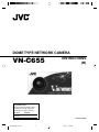
VN-C655
INSTRUCTIONS
(B)
For Customer Use:
Enter below the Serial No. which is
located on the body. Retain this
information for future reference.
Model No.
VN-C655
Serial No.
LW40710-001B
VN-C655(B)_In_Cover
3
05.3.16, 1:19 PM
Safety Precautions
FOR USA AND CANADA
Due to design modifications, data given in this
instruction book are subject to possible change
without prior notice.
CAUTION
RISK OF ELECTRIC SHOCK
DO NOT OPEN
CAUTION:TO REDUCE THE RISK OF ELECTRIC
SHOCK. DO NOT REMOVE COVER (OR
BACK). NO USER-SERVICEABLE PARTS
INSIDE.REFER
SERVICING
TO
QUALIFIED SERVICE PERSONNEL.
The lightning flash wish arrowhead
symbol, within an equilateral triangle is
intended to alert the user to the presence of uninsulated "dangerous voltage" within the product's enclosure that
may be of sufficient magnitude to constitute a risk of electric shock to persons.
The exclamation point within an equilateral triangle is intended to alert the
user to the presence of important operating and maintenance (servicing)
instructions in the literature accompanying the appliance.
Information for USA
This device complies with part 15 of the FCC Rules.
Changes or modifications not approved by JVC could
void the user’s authority to operate the equipment.
This equipment has been tested and found to comply
with the limits for a Class A digital device, pursuant
to Part 15 of the FCC Rules. These limits are
designed to provide reasonable protection against
harmful interference when the equipment is operated
in a commercial environment. This equipment
generates, uses, and can radiate radio frequency
energy and, if not installed and used in accordance
with the instruction manual, may cause harmful
interference to radio communications. Operation of
this equipment in a residential area is likely to cause
harmful interference in which case the user will be
required to correct the interference at his own
expense.
This device complies with Part 15 of the FCC Rules.
Operation is subject to the following two conditions:
(1) This device may not cause harmful interference,
and (2) this device must accept any interference
received, including interference that may cause
undesired operation.
WARNING:
TO REDUCE THE RISK OF FIRE OR
ELECTRIC SHOCK, DO NOT
EXPOSE THIS APPLIANCE TO RAIN
OR MOISTURE.
AVERTISSEMENT:
POUR EVITER LES RISQUES
D’INCENDIE OU D’ELECTROCUTION, NE PAS EXPOSER
L’APPAREIL A L’HUMIDITE OU A LA
PLUIE.
INFORMATION (FOR CANADA)
RENSEIGNEMENT (POUR CANADA)
This Class A digital apparatus complies with
Canadian ICES-003.
Cet appareil numérique de la Class A est
conforme á la norme NMB-003 du Canada.
WARNING (FOR EUROPE):
This is a Class A product. In a domestic environment
this product may cause radio interference in which
case the user may be required to take adequate
measures.
䡵 This installation should be made by a qualified
service person and should conform to all local
codes.
䡵 This installation shall be in accordance with the
National Electrical Code, ANSI/NFPA 70.
䡵 This product shall be powered by a Listed Class
2 power supply only.
䡵 Any Mention in this manual of Alarm inputs/
outputs have not been evaluated by UL to be
used for Burglar Alarm Functionality.
2
C655(B)_p2-22
2
05.3.16, 1:20 PM
These are general IMPORTANT SAFEGUARDS and certain items may
not apply to all appliances.
IMPORTANT SAFEGUARDS
1.
2.
3.
4.
5.
6.
7.
8.
9.
10.
11.
12.
13.
14.
15.
16.
17.
18.
19.
Read all of these instructions.
Save these instructions for later use.
All warnings on the product and in the operating instructions should be adhered to.
Unplug this appliance system from the wall outlet before cleaning. Do not use liquid cleaners or aerosol
cleaners. Use a damp cloth for cleaning.
Do not use attachments not recommended by the appliance manufacturer as they may cause hazards.
Do not use this appliance near water - for example, near a bathtub, washbowl, kitchen sink, or laundry tub, in
a wet basement, or near a swimming pool, etc.
Do not place this appliance on an unstable cart, stand, or table. The appliance may
PORTABLE CART WARNING
fall, causing serious injury to a child or adult, and serious damage to the appliance.
(symbol provided by RETAC)
Use only with a cart or stand recommended by the manufacturer, or sold with the
appliance. Wall or shelf mounting should follow the manufacturer’s instructions, and
should use a mounting kit approved by the manufacturer. An appliance and cart
combination should be moved with care.
Quick stops, excessive force, and uneven surfaces may cause the appliance and
cart combination to overturn.
Slots and openings in the cabinet and the back or bottom are pro-vided for ventilaS3125A
tion, and to insure reliable operation of the appliance and to protect it from overheating, these openings must not be blocked or covered. The openings should never
be blocked by placing the appliance on a bed, sofa, rug, or other similar surface.
This appliance should never be placed near or over a radiator or heat register. This appliance should not be
placed in a built-in installation such as a bookcase unless proper ventilation is provided.
This appliance should be operated only from the type of power source indicated on the marking label. If you
are not sure of the type of power supplied to your home, consult your dealer or local power company. For
appliance designed to operate from battery power, refer to the operating instructions.
This appliance system is equipped with a 3-wire grounding type plug (a plug having a third (grounding) pin).
This plug will only fit into a grounding-type power outlet. This is a safety feature. If you are unable to insert the
plug into the outlet, contact your electrician to replace your obsolete outlet. Do not defeat the safety purpose
of the grounding plug.
For added protection for this product during a lightning storm, or when it is left unattended and unused for
long periods of time, unplug it form the wall outlet and disconnect the antenna or cable system. This will
prevent damage to the product due to lightning and power-line surges.
Do not allow anything to rest on the power cord. Do not locate this appliance where the cord will be abused by
persons walking on it.
Follow all warnings and instructions marked on the appliance.
Do not overload wall outlets and extension cords as this can result in fire or electric shock.
Never push objects of any kind into this appliance through cabinet slots as they may touch dangerous voltage
points or short out parts that could result in a fire or electric shock. Never spill liquid of any kind on the
appliance.
Do not attempt to service this appliance yourself as opening or removing covers may expose you to dangerous voltage or other hazards. Refer all servicing to qualified service personnel.
Unplug this appliance from the wall outlet and refer servicing to qualified service personnel under the following conditions:
a. When the power cord or plug is damaged or frayed.
b. If liquid has been spilled into the appliance.
c. If the appliance has been exposed to rain or water.
d. If the appliance does not operate normally by following the operating instructions. Adjust only those controls that are covered by the operating instructions as improper adjustment of other controls may result in
damage and will often require extensive work by a qualified technician to restore the appliance to normal
operation.
e. If the appliance has been dropped or the cabinet has been damaged.
f. When the appliance exhibits a distinct change in performance - this indicates a need for service.
When replacement parts are required, be sure the service technician has used replacement parts specified
by the manufacturer that have the same characteristics as the original part. Unauthorized substitutions may
result in fire, electric shock, or other hazards.
Upon completion of any service or repairs to this appliance, ask the service technician to perform routine
safety checks to determine that the appliance is in safe operating condition.
3
C655(B)_p2-22
3
05.3.16, 1:20 PM
Introduction
Thank you for purchasing this product.
(These instructions are for VN-C655U.)
Before beginning to operate this unit, please read the instruction manual carefully in
order to make sure that the best possible performance is obtained.
Contents
Introduction
Preparation
Contents ................................................................................................. 4
Characteristics ....................................................................................... 6
Operating Precautions ........................................................................... 6
Items Included ........................................................................................ 9
Operating Environment .......................................................................... 9
Latest Updates ....................................................................................... 9
Name and Function of Parts ................................................................ 10
Connection Examples .......................................................................... 12
Preparation Procedure ......................................................................... 13
Step 1 Connection/Installation
1-1 Connecting Cables ..................................................................... 14
1. Making the hole ........................................................................ 14
2. Connect the cables .................................................................. 14
3. Connection to Alarm Input/Output Terminal ............................. 15
4. Connection of LAN Cables ....................................................... 16
5. Connection of Coaxial Cables .................................................. 17
6. Connection of Conveter Unit .................................................... 18
1-2 Attachment of Ceiling Mount ...................................................... 19
1-3 Installing the Camera ................................................................. 21
Settings
(VN-C655U Setup
Tool)
Step 2 Network Settings
2-1 Installing the Software ................................................................ 23
2-2 Setting PC's IP Address [Windows XP] ..................................... 24
Setting PC's IP Address [Windows 2000] .................................. 26
2-3 Setting IP Address for this Camera Using the "VN-C655U Setup Tool" .. 28
2-4 Other Settings Using the "VN-C655U Setup Tool" ..................... 30
1. Password Setting ..................................................................... 31
2. Multicast ................................................................................... 32
3. Alarm Setting ........................................................................... 34
4. Recording Setting .................................................................... 40
5. Private Mask Setting ................................................................ 42
6. Motion Detection Setting .......................................................... 43
7. Web .......................................................................................... 45
8. FTP Server ............................................................................... 46
9. FTP Client Setting .................................................................... 47
10. Black & White Setting ............................................................... 49
11. Time Setting ............................................................................. 51
12. Memory Information ................................................................. 52
2-5 Registering Connected Camera Using the "V.Networks Controller" . 52
4
C655(B)_p2-22
4
05.3.16, 1:20 PM
Step 3 Setting Using the V.Networks Controller
Settings
(V.Networks
Controller)
Operation
(V.Networks
Controller)
Operation
(Web Browser)
Others
3-1 Starting Up the V.Networks Controller ....................................... 54
3-2 Features that Allow Setting Using the V.Networks Controller .... 55
3-3 Motion Detection Standby .......................................................... 57
3-4 Image Size and Inversion .......................................................... 58
3-5 Image Quality Setting ................................................................ 59
3-6 Frame Rate ................................................................................ 65
3-7 Preset Position Setting ............................................................... 66
3-8 Alarm Setting ............................................................................. 67
3-9 Pan/Tilt Setting ........................................................................... 69
3-10 Auto Pan Setting ..................................................................... 70
3-11 Auto Patrol Setting .................................................................. 72
3-12 Auto Trace Setting .................................................................. 74
3-13 Time Stamp ............................................................................ 76
3-14 Changing Registered Information .......................................... 77
Step 4 Operating Using the V.Networks Controller
Features that Allow Operation Using the V.Networks Controller .. 78
Record/Stop ............................................................................... 80
Playback .................................................................................... 81
Cautions on Record/Play Functions ........................................... 83
Snapshot .................................................................................... 84
4-1
4-2
4-3
4-4
4-5
Step 5 Operating Using a Web Browser
5-1 Operating Environment .............................................................. 85
5-2 Access Authorization Level ........................................................ 86
5-3 Starting Up the Web Browser .................................................... 87
5-4 Setting Using the Web Browser ................................................. 88
1. Other Settings .......................................................................... 90
2. Control ..................................................................................... 93
3. Image Setting ........................................................................... 94
4. PAN/TILT Setting ...................................................................... 97
5. Position Memory Setting .......................................................... 98
6. View Setting ............................................................................. 99
7. Alarm Setting ......................................................................... 100
8. FTP Setting ............................................................................ 102
9. Auto Pan Setting .................................................................... 104
10. Auto Patrol Setting ................................................................. 105
11. Auto Trace Setting .................................................................. 106
12. Black & White Setting ............................................................. 107
13. Schedule Setting .................................................................... 107
14. Private Mask Setting .............................................................. 108
5-5 Viewing Still Images ................................................................. 109
5-6 Viewing Live Images ................................................................ 110
5-7 Image Link ............................................................................... 111
Troubleshooting .................................................................................. 112
Specifications ..................................................................................... 114
5
C655(B)_p2-22
5
05.3.16, 1:20 PM
Introduction
Characteristics
䡵 High-speed Rotating Table
High-speed rotating table with a horizontal
panning speed of 300˚/sec and vertical tilting
speed of 180˚/sec makes it possible to recall
a preset position quickly.
䡵 Optical + Electronic zooming
The 25X optical zoom lens and 10X electronic
zoom circuitry allows the camera to be used
even in surveillance situations in which the
object is very small.
䡵 Day/Night Surveillance
When the light is low, the camera is able to switch
automatically to the high-sensitive (Black &
White) mode by turning ON/OFF the IR filter.
It also suppor ts infrared illuminators
(wavelength of 850 nm to 880 nm).
䡵 Employment of a highly-sensitive CCD
and bright zoom lens
Employment of a highly-sensitive CCD and
bright zoom lens with a maximum aperture
ratio of F1.6 (at the Wide end) produces a
highly sensitive color mode of 2.0 lx (AGC:
20 dB, 50%).
䡵 Frame Rate
Supports a maximum frame rate of 30 fps
when resolution is 640 x 480 in the JPEG
compression format.
䡵 Supports Multicast
Support for multicast enables sending of an
image data to multiple PCs on the network
at one time without lowering the frame rate.
䡵 DSP with a wide dynamic range
Even objects that have a large difference in
brightness can be monitored clearly.
䡵 Private Mask Feature
This feature enables setting to mask a certain
portion of the shooting area if it is to be
hidden.
䡵 Motion Detection Feature
Enables output of alarm upon detecting
motion of images within a specified area.
䡵 Built-in Web Server
Enables browsing using the Internet Explorer.
Operating Precautions
䡵 To save energy, turn off the power supply of
the system when not in use.
䡵 This camera is intended for indoor use. It
cannot be used outdoors.
䡵 This camera has been designed for suspension
from ceilings. Fixing it to the ground surface or
at an angle may cause malfunction or shorten
the product's service life.
䡵 Do not install or use the camera in the
following locations.
• Places exposed to rain or water
• Places containing vapor or oil soot, such
as kitchens
• Places exceeding the operating ambient
temperature range (0˚ to 40˚)
• Places where corrosive gases are
generated
• Places nearby radiation or X-rays as well
as sources of strong radio waves or
magnetism
• Places subject to vibration
• Places with excessive dust
䡵 Insufficient ventilation may cause the camera
to malfunction. Be careful not to block
ventilation around the camera.
This camera radiates heat from its surfaces
䡵
䡵
䡵
䡵
䡵
(top panel facing ceiling and side panel). Do
not install at a location that may trap heat,
such as near the walls.
Do not install at a location that may expose the
camera directly to cool air, such as nearby the
air outlet of air conditioners. This may cause
moisture to condense within the dome cover.
Dew condensation may occur when there is
a drastic change in the ambient temperature
of the camera, hence causing a malfunction.
When the camera is installed at such
locations, turn on the power after allowing it
to dry for a few hours.
Do not point the camera lens at a strong light
source such as the sun. Doing so may cause
the camera to malfunction.
This camera contains a built-in AGC circuit.
As a result, gain increases at dark places
and screen may appear grainy. This is not a
malfunction.
When an equipment that generates a strong
magnetic field, such as transceivers, is used
near this camera with the AGC turned on, beat
noises may appear in the image. When using
a transceiver, therefore, place it at least 3 m
away from this camera.
6
C655(B)_p2-22
6
05.3.16, 1:20 PM
䡵 If this camera or cable connected this unit is
used near a location where strong electrical
or magnetic waves are generated (eg. radios,
TVs, transformers, monitors, etc.), noise
interference may occur in the image or its
color may be affected.
䡵 When the AGC circuit is on, brightness of
the screen may not change upon switching
the Auto Iris mode (Normal, + or -) using the
V.Networks Controller. This is due to the
automatic gain boost feature that is activated.
In this case, set AGC to OFF or use the
manual iris mode.
䡵 Under cer tain brightness conditions,
switching the Auto Iris mode (Normal, + or -)
using the V.Networks Controller may not bring
about any change in brightness. In this case,
set the iris to the manual mode.
䡵 When this camera is used in the White Balance
(ATW) mode, the colors captured may differ
slightly from the actual colors due to the
operational principles of the auto-tracking
white balance circuit. This is not a malfunction.
䡵 When shooting a bright object (eg. lamps,
etc.), white vertical streaks may appear on
the object on the screen. This is a
phenomenon (smear phenomenon) normal
to CCDs (solid-state image pickup devices)
and is not a malfunction.
䡵 When the camera is used to monitor the
same position over prolonged hours (such
as 24 hours of continuous monitoring),
contact resistance of the panning mechanism
may increase. This may cause noise
interference in the image or unstable
operation of the V.Networks Controller. To
prevent this from occurring, turn the power
of the system off and on again (to initialize
camera) once a week and clean the contacts.
䡵 The dome cover is hemispherical in shape, and
therefore images tend to be distorted at the
edges of the hemisphere. The edges of the
hemisphere is masked for this camera. When
the camera is tilted and pointed in the horizontal
direction, therefore, edges of the hemisphere
may enter the angle of view, hence causing
the upper end of the screen to appear dark
and the image to go out of focus.
䡵 When shooting an object that is near a light
source (eg. lightings) or with a large
difference in brightness, ghosting may occur
on the screen. This phenomenon is due to
the characteristics of the dome cover and
built-in lens and is not a malfunction.
䡵 Ensure to use the Converter Unit that has
been supplied.
䡵 When playing back images by connecting a
coaxial cable to the VIDEO OUT terminal,
the image on the screen may appear shaky
(rotational motions are not smooth) when
using the Manual or Auto Pan operation
par ticularly near the Tele end. This
phenomenon is due to the characteristics of
the motor and is not a malfunction.
䡵 Certain hubs/switches that are equipped with
the SNMP feature may come with a broadcast
or multicast control function. Proper viewing
of multicast images created by this camera
may not be possible if this function is enabled.
䡵 Do not touch the dome cover with your hand.
This may dirty the cover and cause the image
quality to deteriorate.
䡵 To clean the camera.
• Do so upon turning off the power.
• Use a lens cloth (or paper) to remove dirt
from the dome cover. The camera may
acquire dirt over a short period of time,
depending on the environment of use.
When there is excessive dirt, wipe using a
lens cloth (or paper) upon wetting it in a
neutral detergent diluted with water.
䡵 Do not connect cameras other than VN-C655
to the ceiling mount. Doing so may cause the
camera to malfunction.
䡵 Consumable Parts
The following parts are consumable. Please
replace them accordingly after a certain number
of hours or count of operations. The service lives
given below are only reference values and may
vary according to the operating environment and
conditions. Note that replacement of consumable
parts is chargeable even within the warranty period.
• Zoom lens assembly
Zooming operation : 2 million times
Focusing operation : 4 million times
• Slip rings
: Approx. 5 million
operations
• Cooling fan
: Approx. 30,000 hours
䡵 Zooming operation
Focus may deviate slightly upon stopping of a
zoom operation near the Tele end manually or
using a preset selection.
In addition, the manual zooming operation
may not always be smooth.
These phenomena are due to the
characteristics of the built-in lens and are not
malfunctions.
7
C655(B)_p2-22
7
05.3.16, 1:20 PM
Introduction
Operating Precautions (continued)
䡵 Auto Focus
Although this camera comes with the one-push
auto focus and EASY AF auto focus features, auto
focusing may sometimes be impossible
depending on the object and camera settings.
When this occurs, adjust the focus manually.
Objects for which auto focusing is
difficult
• When brightness of the screen is extremely
high (bright)
• When brightness of the screen is extremely
low (dark)
• When brightness of the screen varies
continuously (eg. flashing lights, etc.)
• When there is poor contrast
• When vertical stripe patterns recur on the
screen
䡵 Preset Positions
• The is a total of 100 preset positions that
can be set, including the home position.
• The TILT position can be set and operated
only between 0° to 90° even when the item
“FLIP” is set to ON.
䡵 Image sending may be affected when this is
done on a network where multicast
transmission devices are connected, or on
networks for which there is transmission of
voluminous broadcast data. When this
occurs, ensure to employ a system design
that separates the camera from other
multicast or broadcast devices by making use
of a switching valve or VLAN with a multicast
control function.
Camera settings for which auto focusing
is difficult
• When the AGC gain level increases and the
screen becomes grainy
• When SENSE UP is activated and the image
contains only little motion.
䡵 Read Me
Please read through the "Read Me" file in the
CD-ROM together with this instruction
manual.
Warning
Install at places that are strong enough
to support the camera weight.
Install this camera at places that are strong
enough to support its weight upon taking
into consideration the vibration force during
high-speed rotation as well as its mass
(approx. 2.2 kg). For ceiling materials that
are weak, such as overlay plywood and
plaster boards, reinforce by applying
reinforcements (veneer plywood). If
reinforcement is inadequate, image on the
monitor screen may be blurred due to
vibrations. In the worst scenario, it may even
fall and cause serious injuries if there is
someone underneath.
How to Use This Manual
Characters and symbols used in this manual
Caution
Points to pay attention to during operation.
Note
Details for reference, such as functions or constraints during use.
☞
Pages or items to refer to.
* JVC shall not be held liable for any loss or damage to the customer or any claim from a third
party arising from the use of this software.
Specifications of this software are subject to alteration for improvement without prior notice.
All product names that appear in this document are the trademarks or registered trademarks
of their respective companies. Marks and symbols such as ™,® and © do not appear in this
document.
8
C655(B)_p2-22
8
05.3.16, 1:20 PM
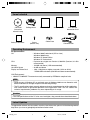
Items Included
CD-ROM
(instruction
manual inside)
Ceilling Mount
Safety Precautions
Screw
(M3x12 mm)
Read Me First
Warranty Card
JVC Service
Information Card
Cable Plate
Converter Unit
Operating Environment
PC Specifications
OS
CPU
Memory
Hard Disk Space
Display and Video Card
: Windows 2000 Professional (SP1 or later)
Windows 2000 Server
Windows XP Home Edition
Windows XP Professional
: Equivalent to or higher than Pentium 3, 500 MHz (Pentium4, 3.2 GHz
recommended)
: 128 MB and above (1 GB recommended)
: 20 MB and above
: 1024 x 768 pixels or higher, true color (24 bit or 32 bit)
*VRAM 8MB and above (256 MB and above recommended)
LAN Environment
• 10BASE-T/100BASE-TX networks mutually connected by IEEE802.3-compliant hubs
Note
• General users of Windows XP or restricted users of Windows 2000 are not allowed to add/
delete V.Networks or change snapshot and recording settings.
• The PC specifications above are only reference values for smooth operation of this application,
and are not meant to guarantee operation of this application. Even if the PC satisfies the
technical requirements, problems may occur depending on its usage.
Caution
If the OS specifications of the PC to be used are higher, they precede those described above.
Latest Updates
To upgrade the software version or obtain any other latest information, please visit the following website:
http://www.jvc-victor.co.jp/english/pro/vnetworks/index-e.html
9
C655(B)_p2-22
9
05.3.16, 1:20 PM
Introduction
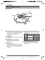
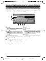
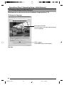
Name and Function of Parts
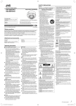
䡵Ceiling Mount
6
5
1
4
3
2
1
[MONITOR OUT] Coaxial Cable Terminal
Output Terminal of a composite video signal
(1 Vp-p) with an output impedance of 75 Ø, to
be connected to video monitor, etc.
(☞Page 17)
2
Locking Screw
Tighten this screw to fasten the camera clamping bracket.
3
[POWER INPUT DC18V] Terminal
Connect to a supplied Converter Unit.
(☞Page 18)
4
Safety Wire Hole
To prevent the possibility of the entire camera
falling down, attach the safety wire between
this hole and a secure attaching position in
the ceiling.
5
[ALARM I/O]Alarm Input/Output Terminals
Terminals for Alarm input and Alarm output.
(☞ Page 15)
Signal Name
Pin No.
1
ALM OUT 1
ALARM OUT
2
ALM OUT 2
3
ALM IN 1
ALARM IN
4
ALM IN 2
GND
5
6
[10BASE-T/100BASE-TX] Connector
For network connection with a LAN cable.
(☞ Page 16)
10
C655(B)_p2-22
10
05.3.16, 1:20 PM
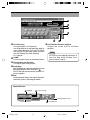
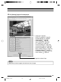
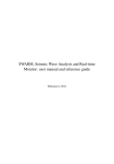
䡵Ceiling Mount
䡵Camera
%
0
9
9
!
7
$
@
8
#
(Camera Connector side)
7
Camera Terminal (Female)
Connect to 0, the Male Terminal on the camera.
@
Dome Cover
The dome cover is fragile. Take care when
handling it.
8
Drop Prevention Hook
Attach the Drop Prevention Wire & to this hook
to prevent the camera from falling.
#
Lens
The lens is not a replaceable item.
9
Clamping Holes (x 4)
Attach the camera to a ceiling using these
holes.
$
Camera Clamping Bracket
In order to clamp the camera onto the Ceiling
Mount, insert and tighten the Locking Screw
2 into this bracket.
%
Drop Prevention Wire
Attach this wire to the Drop Prevention Hook
8 on the Ceiling Mount.
0 Camera Terminal (Male)
Connect to 7, the Female Camera Terminal
on the Ceiling Mount.
!
Camera Body Cover
Do not remove the camera body cover while
the camera is installed on a ceiling. Doing so
will cause the dome cover to fall down.
11
C655(B)_p2-22
11
05.3.16, 1:20 PM
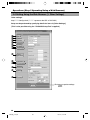
Preparation
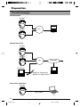
Connection Examples
LAN Connection
VN-C655
LAN
VN-C655
PC
Network Connection
VN-C655
VN-C655
LAN
INTERNET
FTP Server
Images are automatically
updated at a regular interval.
PC
PC
Peer-to-Peer Connection
VN-C655
Cross Cable
PC
12
C655(B)_p2-22
12
05.3.16, 1:20 PM
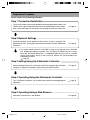
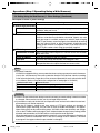
Preparation Procedure
Set the camera in the following procedure.
Step 1 Connection/Installation
Firstly, make a hole in the ceiling, followed by connecting the power cable, LAN
cable or alarm signal cable to the terminal of the ceiling mount of this camera.
Next, attach the camera to the ceiling. Do not forget to attach the safety wire.
☞Page 14
Step 2 Network Settings
Install the software, set the network for this camera as well as using the "VNC655U Setup Tool", and register the connected camera with the "V.Networks
Controller".
☞Page 23
● In a system where more than 1 VN-C655 is used, turn on the power for a VN-C655
first, followed by setting the camera until "2-3 Setting IP Address for this Camera
Using the 'VN-C655U Setup Tool' " is completed. Upon doing so, turn on a second
camera and perform setting in the same way. Perform the same procedure for
subsequent cameras.
(☞Page 18)
Step 3 Setting Using the V.Networks Controller
Perform settings for Auto Pan, Auto Patrol, Auto Trace, Image Quality and Alarm
using the "V. Networks Controller" software that has been installed.
☞Page 54
Step 4 Operating Using the V.Networks Controller
The "V. Networks Controller" can also be used to perform recording/playback
operations.
☞Page 78
Step 5 Operating Using a Web Browser
☞Page 85
Operation is possible via a web browser.
13
C655(B)_p2-22
13
05.3.16, 1:20 PM
Preparation (Step 1 Connection/Installation)
1-1 Connecting Cables
Cautions
● Attachment of a embedded cover in the ceiling (recess bracket) may be mandatory in certain
regions. If this is so, ensure that the embedded cover (recess bracket) is securely attached
before installing the camera.
● Ensure to attach the cover for the ceiling mount. Installation is not possible without attaching
the cover. In addition, the cover also prevents penetration of foreign objects into the ceiling
mount. Penetration of foreign objects may cause a malfunction or, in the worst scenario,
cause smoking or fire.
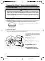
1. Making the hole
Make a hole for passing the connection cables through the inner side of the ceiling.
Make a 90 mm (3.5 inches) diameter hole in the ceiling.
(☞Page 115)
Diameter 90 mm
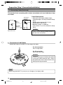
2. Connect the cables
Connect the cables to the terminals on the Ceiling Mount.
Lan cable
The connection cables include Alarm
Signal cable, LAN cable, coaxial cable and
Converter Unit.
Alarm signal cable
1. LAN cable (☞Page 16)
Connect to the hub or PC.
Coaxial cable
Converter Unit
2. Alarm Signal cable (☞Page 15)
Connect to devices with an alarm
output terminal.
3. Coaxial cable (☞Page 17)
Connect to the monitor, etc.
4. Converter Unit (☞Page 18)
Connect to AC 24 V power supply.
14
C655(B)_p2-22
14
05.3.16, 1:20 PM
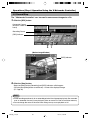
3. Connection to Alarm Input/Output Terminal
1
Connect the alarm input/output terminals to
external devices such as sensors and buzzers.
2
4 mm
Flathead
Screwdriver
Alarm Signal
Cable
1 Loosen
the screws on both edges of the
terminal block using a flathead screwdriver,
followed by dismantling it as shown in the left
diagram.
2 Strip the coating of the alarm signal cable by
3
Flathead
Screwdriver
4
about 4mm before inserting it into the terminal.
3 Turn the screw on the side to fasten the alarm
signal cable.
1
4 Upon
fastening the alarm signal cable, reinstall the terminal block that has been
dismantled in Step 1.
Note
Cable Specifications
50 m or shorter in length
UL1007, UL1015 or equivalent
AWG#22 to AWG#18 or equivalent
Caution
Due to external noise, the cable may not
function properly even when the cable length
is less than 50 m. In this case, use a shielded
cable or take measures such as keeping the
cable away from the noise source.
This terminal is for connecting with a sensor, infrared, door or metallic, or a manual
switch.
Sensor
Connection
Example 1
VN-C655
DC18V
R
VCC
Terminal
1 or 2
18V
R
OUT
0.6mA
Grounding
Terminal
GND
Sensor
Connection
Example 2
Relay,
switch,
etc.
(Alarm Input
Equivalent Circuit)
OUT
Input Requirements
● No-voltage relay input or NPN open collector
input
● The polarity of the input detection can be
selected via software.
● Make/Break/Toggle (at least 500 ms)
● Circuit current at low level: 0.6 mA
● Voltage applied at high level: 18 V
GND
15
C655(B)_p2-22
15
05.3.16, 1:21 PM
Preparation (Step 1 Connection/Installation)
1-1 Connecting Cables (Continued)
This terminal is for connecting with an alarm annunciator such as an indicator, a lamp
or a buzzer.
Alarm Device
Connection
Example
VN-C655
OUT
Terminal
DC 12 V
R
IN
Grounding
Terminal
GND
Output Requirements
• Equivalent to NPN open collector output
(The output logic is set with [V.Networks Setup
Tool.])
• Allowed applied voltage: DC 12 V max.
• Allowed input current: 50 mA
• Momentary output: 1 to 5000 ms
(The duration is set with [V.Networks Setup
Tool.])
Caution
(Alarm Output
Equivalent Circuit)
Connect the VN-C655 grounding terminal to
the one of the annunciator.
4. Connection of LAN Cables
Connect the camera to a hub or a PC by using a LAN cable.
• For hub connection
Use a straight cable.
• For PC connection
Use a cross-over cable.
Caution
There are a few types of LAN board for which
a cross-over cable cannot be used. Check
the specifications of the LAN board to be used
before performing connection.
Note
When using 100 BASE-TX, ensure to use a Category 5 (or higher) cable.
16
C655(B)_p2-22
16
05.3.16, 1:21 PM
5. Connection of Coaxial Cables
Polyethylene
*
Core Wire
Mesh
Wires
Connecting a 5C-2V or 3C-2V coaxial cable
Strip the coaxial cable according to the
diagram on the left. (Unit: mm)
Notes
7
17
Insulation Tape
Provided screw
Screw removed
in the figure on
the left
Provided cable
plate
• 7C-2V coaxial cables cannot be connected
directly to the terminal block. In this case,
make use of the 5C-2V cable as a junction
cable by connecting it to this camera.
* Fold back the mesh wires and secure
using an insulation tape to prevent them
from becoming loose and causing a
short circuit.
• Video output signal of the VIDEO OUT
terminal is restricted to NTSC signals.
● When mounting the coaxial cable in parallel with
the ceiling mount, remount the provided Cable
plate as shown in the figure.
17
C655(B)_p2-22
17
05.3.16, 1:21 PM
Preparation (Step 1 Connection/Installation)
1-1 Connecting Cables (Continued)
6. Connection of Conveter Unit
Press
2.
1.
Press
Power cable
5mm
Press
Connector
3.
Connect the camera to AC 24 V.
1. Disconnect the connector from the supplied Converter Unit.
It can be disconnected by pressing both ends
as shown in the left figure.
2. Mount the power cable to the connector.
Strip the cover of the power cable (about 5
mm), while pressing down the arrow portion
using a flat screwdriver, insert it into the connector.
to AC 24V
3. Mount the connector.
4. Connect the supplied Converter Unit to
the DC 18V input terminal on the terminal
stand.
4.
When a 2-conductor VVF (Vinyl-insulated vinyl-sheath cable) is used, the maximum connection length
is as shown below. (These are merely the standard reference values.)
Maximum cable length
Wire diameter (mm)
70 m
1.0 or more
180 m
1.6 or more
280 m
2.0 or more
480 m
2.6 or more
Caution
• Connect with the appropriate power-supply voltage. The rated voltage for VN-C655 (Converter
Unit) is AC 24 V, 50 Hz/60 Hz and shall be Class 2.
If a voltage exceeding the rating is supplied, malfunction, or in the worst case, fuming or fire,
may be caused.
• Installation shall be performed by qualified personnel according to regulations of individual
regions.
Notes
Connecting multiple VN-C655 Cameras
In a system where more than 1 VN-C655 is used, turn on the power for a VN-C655 first, followed
by setting the camera until "2-3 Setting IP Address for this Camera Using the 'VN-C655U Setup
Tool' " is completed. Upon doing so, turn on a second camera and perform setting in the same
way. Perform the same procedure for subsequent cameras.
• Default IP address setting for all VN-C655 cameras is 198.168.0.2. When the power for multiple
cameras are turned on at one time under a single LAN environment, therefore, proper access
may not be established due to IP address redundancy. Do not turn on the power of more than
1 camera at the same time.
• When IP address redundancy occurs, ensure that only one VN-C655 exists under a single
LAN environment, and wait for some time (at least 10 minutes). In some cases, the power for
all network devices under the same LAN environment may have to be turned off and on again
to enable access to VN-C655.
18
C655(B)_p2-22
18
05.3.16, 1:21 PM
1-2 Attachment of Ceiling Mount
Caution
Ceiling
Embedded Cover in Ceiling (recess bracket)
• Attachment of a embedded cover in the ceiling
(recess bracket) may be mandatory in certain
regions. If this is so, ensure that the embedded
cover (recess bracket) is securely attached
before installing the camera.
• Please refer to the instruction manual for the cover
in use for details on installation of the embedded
cover (recess bracket).
• For more detail, please contact the JVC.
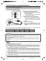
1. Attach
To a ceiling slab or channel
Safety wire
hole
Ceiling Mount
Rubber seals
(Four on each side)
safety wire to prevent camera
from falling down
Connect the ceiling slab or channel to
ceiling mount using the wire to prevent
camera from falling down. Make use of
safety wire mounting hole to connect
ceiling mount and the wire.
(See diagram on the left)
the
the
the
the
Cautions
Choose a wire and ceiling structure with an
appropriate strength and length that may
prevent danger in case the camera falls down.
Notes
• Connect the wire so that it can be insulated
from the ceiling structure.
If the ceiling structure is made of a metallic
material, improper insulation with the
camera may cause noise interference in
the images.
• Safety wires are not provided. Please
purchase commercially available wires on
a separate basis.
19
C655(B)_p2-22
19
05.3.16, 1:21 PM
Preparation (Step 1 Connection/Installation)
1-2 Attachment of Ceiling Mount (Continued)
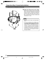
2. Fasten the ceiling mount to the ceiling
While taking care not to catch the connection
cables, attach the Ceiling Mount to the ceiling
using four screws (as shown in the diagram).
Use 8-32 UNC-sized (M4-sized) screws or
bolts. If woodscrews are used, use those with
a diameter of 4.1 mm.
Notes
• Be sure to use 4 screws and attach them
firmly.
• The seals attached to the ceiling-mount
screw holes of the ceiling mount act as an
insulator between the ceiling mount and the
ceiling structure. If the ceiling structure is
made of a metallic material, improper
insulation with the camera may cause noise
interference in the images. To prevent this
from occurring, ensure proper insulation
during installation.
Screws
20
C655(B)_p2-22
20
05.3.16, 1:21 PM
1-3 Installing the Camera
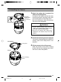
1. Attach
the safety wire to prevent the
camera from falling down
Attach Drop
Prevention Wire
to this hook.
Drop Prevention
Wire
As shown in the diagram, pull out the safety
wire from the camera and hang it to the safety
wire fastening hook on the ceiling mount.
Be sure to connect the safety wire to prevent
the camera from falling down.
Cautions
• Do not connect cameras other than VNC655 to the ceiling mount. Doing so may
cause the camera to malfunction.
• Be sure to connect the safety wire.
Otherwise, the camera may fall to the
ground.
2. Check that the locking screw is loosened
The camera cannot be properly installed if the
locking screw of the ceiling mount is not
loosened.
Ceiling Mount
Locking Screw
3. Fit the camera to the ceiling mount
Check the position of the camera clamping
bracket and that of the locking screw, and fit
the camera to the Ceiling Mount.
Camera
Camera Clamping
Bracket
21
C655(B)_p2-22
21
05.3.16, 1:21 PM
Preparation (Step 1 Connection/Installation)
1-3 Installing the Camera (Continued)
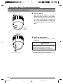
4. Turn the camera
Camera clamping bracket
Make sure that the camera is horizontal,
followed by fitting the camera to the ceiling
mount and turning it in the clockwise direction
until it stops. Upon doing so, check that the
the camera clamping bracket is aligned with
the position of the locking screw of the ceiling
mount.
Rotate the
camera
clockwise.
Locking Screw
5. Fasten the locking screw
Fasten the locking screw using a flathead
screwdriver.
Cautions
If the locking screw is not securely fastened,
the camera may vibrate or fall down.
Be sure to fasten the locking screw firmly.
* To dismantle the camera, perform procedure
from steps 1 to 5 in the reverse order.
Tighten the locking screw.
22
C655(B)_p2-22
22
05.3.16, 1:21 PM
Settings (Step 2 Network Settings)
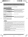
2-1 Installing the Software
To operate this camera, you will have to install the necessary software according to
the following procedure from the CD-ROM supplied.
~~~~~~~~~~~~~~~~~~~
Installing the V.Networks Controller
1. Execute "Setup.exe" in the [JVC] folder.
2. Follow instructions on the screen to install the software.
3. If installation is successful, the † "V.Networks Controller" icon will be displayed in the [Start] †
[V. NETWORKS] folder.
[Programs]
Installing the VN-C655U Setup Tool
1. Execute "Setup.exe". This is located inside the [Setup] folder of the [JVC] folder.
2. Follow instructions on the screen to install the software.
3. If installation is successful, the † "VN-C655U Setup Tool" icon will be displayed in the [Start] †
[V. NETWORKS] folder.
[Programs]
23
C655(B)_p23-39
23
05.3.16, 1:21 PM
Settings (Step 2 Network Settings)
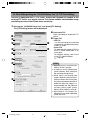
2-2 Setting PC's IP Address [Windows XP]
Upon installing the camera, set the IP address of the PC that is used to operate this
camera.
For Windows XP, set according to the following procedure.
(For Windows 2000, ☞ Page 26)
Note
Under a DHCP environment and when the IP address assigned to V. Networks is already known,
it will not be necessary to perform 2-2 "Setting PC's IP Address" as the PC's IP address is
automatically acquired from the DHCP server.
1. Click
.
• Right-click on [My Network] and select [Properties].
2. Slect the network for which the PC that operates this camera is connected to.
• Right-click to select [Properties].
Ensure that it is selected.
Note
Select "Install (N) ..." if [Client for
Microsoft Networks] or [Internet
Protocol (TCP/IP)] is not displayed.
24
C655(B)_p23-39
24
05.3.16, 1:21 PM
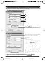
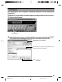
3. Select [Internet Protocol (TCP/IP)] and click [Properties].
1 Select [Internet Protocol (TCP/IP)].
2 Click [Properties].
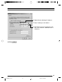
4. Select [Use the following IP address], set the [IP address] and [Subnet mask] and
click
.
1 Select [Use the following IP address].
2 Set [IP address] to 192.168.0.3.
Note
• Make sure to note down the original
IP address before changing.
• Do not use the same IP address
elsewhere within the same network
environment.
3 Set Subnet mask to an appropriate value.
Ask the network administrator if
necessary.
4 Click
5. Click
.
on the [Local Area Connection Properties] screen.
25
C655(B)_p23-39
25
05.3.16, 1:21 PM
Settings (Step 2 Network Settings)
2-2 Setting PC's IP Address [Windows 2000]
Upon installing the camera, set the IP address of the PC that is used to operate this camera.
For Windows 2000, set according to the following procedure.
1. Click
.
• Select [Settings] and click [Properties].
2. Double-click [Network and Dial-up Connection].
3. Double-click [Local Area Connection].
1 Click
.
2 Select [Internet Protocol (TCP/IP)].
3 Click
.
26
C655(B)_p23-39
26
05.3.16, 1:22 PM
4 Select [Use the following IP address].
5 Set [IP address] to 192.168.0.3.
6 Set Subnet mask to an appropriate value.
Ask the network administrator if
necessary.
4.Click
.
27
C655(B)_p23-39
27
05.3.16, 1:22 PM
Settings (Step 2 Network Settings)
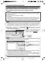
2-3 Setting IP Address for this Camera Using the "VN-C655U Setup Tool"
Set the IP address for VN-C655 using the "VN-C655U Setup Tool" that has been installed.
(This "VN-C655U Setup Tool" only allows connection of VN-C655.)
Caution
• Upon turning on the power of this camera, it may take about 60 seconds before it can be
connected to the PC.
• At the factory, DHCP is enabled for VN-C655.
• Using DHCP
JVC does not recommend operating VN-C655 with the DHCP function enabled because a
different IP address may be assigned upon the renewal of the leasing contract. The DHCP
function of VN-C655 is included with the aim to simplify installation/setting procedures.
Note
• To connect to a VN-C655 for which DHCP has been enabled, the DHCP server must exist in an
environment where the assigned IP address and MAC address are clearly defined. If the DHCP
server is not found, it will automatically start up using the static IP address after 60 seconds.
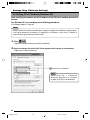
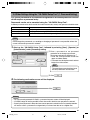
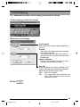
1. Select [Start] † [Programs] † [V.NETWORKS] †
[VN-C655U Setup Tool] to start
up the "VN-C655U Setup Tool".
1 Enter the IP address of the camera to be
connected in [Connection IP address].
Default IP address is 192.168.0.2.
2 Click
.
Note
To view the IP address of the connected camera, click "Search".
The [V.Networks Search] screen is
displayed.
Click
to start search and
a [V.Networks IP Address List] will
appear.
• [TimeOut] is for setting the time for searching (1 to 30 seconds). If no IP address is displayed
upon searching, change the value to a longer time and search again.
• If the [V.Networks] on the LAN has a different subnet from that of the PC, connection may not
be possible even if the IP address of the camera is found via search. Change the IP address
of the PC to an appropriate value and connect the camera.
28
C655(B)_p23-39
28
05.3.16, 1:22 PM
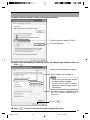
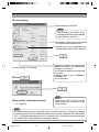
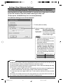
2. Check settings.
1 Select whether to use DHCP.
Note
The IP address of the DHCP server
and other information can be checked
when [DHCP] is selected.
2 Change the IP address to the one assigned
to or approved by the administrator.
3 Set Subnet mask to an appropriate value.
Ask the network administrator if necessary.
4 Click
For other settings, ☞ next page
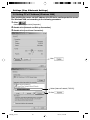
3. Click
.
.
[V.Networks ID] works as an identification
code set to VN-C655. Only alphanumeric
characters can be used.
This ID does not directly affect operation
by the user.
Normally, the ID is set as CAM00001,
CAM00002, etc.
(0 to 8 characters)
Click
.
Note
4. Start up the "V.Networks Controller".
(☞ Page 54)
Upon clicking OK, VN-C655 will be
automatically reset and the set values
will be enabled.
Note
In a system where more than 1 VN-C655 is used, turn on the power for a VN-C655 first, followed
by setting the camera until "2-3 Setting IP Address for this Camera Using the 'VN-C655U Setup
Tool' " is completed. Upon doing so, turn on a second camera and perform setting in the same
way. Perform the same procedure for subsequent cameras.
29
C655(B)_p23-39
29
05.3.16, 1:22 PM
Settings (Step 2 Network Settings)
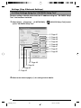
2-4 Other Settings Using the "VN-C655U Setup Tool"
Perform setting of details other than the IP address using the "VN-C655U Setup
Tool" that has been installed.
1. Select [Start] † [Programs] † [V.NETWORKS] †
[VN-C655U Setup Tool] to start
up the "VN-C655U Setup Tool".
☞ Page 31
☞ Page 43
☞ Page 49
☞ Page 45
☞ Page 46
☞ Page 47
☞ Page 51
☞ Page 52
☞ Page 40
☞ Page 34
☞ Page 42
☞ Page 32
2. Refer to the relevant pages (☞) for setting of other details.
30
C655(B)_p23-39
30
05.3.16, 1:22 PM
2-4 Other Settings Using the "VN-C655U Setup Tool" (1. Password Setting)
PCs (users) connected to this camera are regulated via an access protection function
which requires a password entry.
Passwords can be set or canceled using the "VN-C655U Setup Tool".
A different password can be set for each of the 3 authorization levels, namely user, operator and administrator.
Authorization Level
User
Operator
Administrator
Allowed Access
Viewing of motion images only
All operations using the V.Networks Controller
All of the above and all settings using the VN-C655U Setup Tool
Note
Do not forget the passwords as canceling or changing of passwords is not possible unless the
current and correct password is entered.
1. Start
up the "VN-C655U Setup Tool", followed by selecting [User], [Operator] or
[Administrator] under [Password] setting.
1 Enter a password to set password
protection or to change a password.
Characters entered are displayed as *.
• Enter the same password in both the
upper and lower boxes.
• Password must be alphanumeric and not
longer than 8 characters.
Note
To cancel the password setting, leave
the entry box blank and click OK.
2 Click
.
2. The following confirmation screen will be displayed.
Click
.
Notes
• For a password-protected VN-C655, a password request screen will be displayed.
• VN-C655 setup will not be possible unless the correct administrator password is entered.
• Security level increases in the order from user to operator to administrator. Password protection
will not be valid if a password is assigned only to a lower level but not to a higher one.
31
C655(B)_p23-39
31
05.3.16, 1:22 PM
Settings (Step 2 Network Settings)
2-4 Other Settings Using the "VN-C655U Setup Tool" (2. Multicast)
Selecting Multicast mode allows VN-C655 to send the same image data to multiple
PCs on the network at one time without lowering the frame rate.
1. Start up the "VN-C655U Setup Tool" and select [Multicast].
The [Multicast Setting] screen will be displayed.
1 Select [Multicast Mode].
2 Select the mode for acquiring images.
: Set to Normal when using a
narrow bandwidth network.
High Speed : A maximum transmission
rate of 30 fps is possible
for 640 x 480 images.
Normal
Notes
• Images are divided into IP fragments
when set to High Speed.
• Do not set to High Speed for narrow
bandwidth networks.
• Maximum data transmission capacity
is 8Mbps.Even when High Speed is
selected, a maximum rate of 30 fps
may not be possible for 640 x 480
images depending on the image size.
• The MTU(Maximum Transmission
Unit) sizes during image acquisition
are as follows.
Transmission Mode
Normal
MTU Size (Bytes)
1430 Bytes
High Speed
1500 Bytes
Multicast
• Set the multicast address within the range between 225.0.0.0 to 239.255.255.255. Do not set
the same multicast address for different devices on the same system.
• To view VN-C655 images in the multicast mode through a router, either the following operating
environment or router setting will be required.
1 The router supports IGMP Ver2 and is synchronized with the starting and stopping of the
multicast transmission, and the router settings can be dynamically changed.
2 If the router does not support IGMP Ver2, a static route for multicast must be set to the
router.
• When there are multiple cameras on the same subnet that are set to the multicast mode, set
up a network using a hub that supports the IGMP snooping feature.
32
C655(B)_p23-39
32
05.3.16, 1:22 PM
It is possible to search for the multicast address of a VN-C655 that is connected to
the network.
1. Start up the "VN-C655U Setup Tool".
Click
.
2. The [V.Networks Search] screen is displayed.
Click
.
3. The [Multicast Address Search] screen is displayed.
1 Select
.
Start search.
4. The search result is displayed.
33
C655(B)_p23-39
33
05.3.16, 1:22 PM
Settings (Step 2 Network Settings)
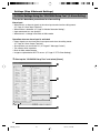
2-4 Other Settings Using the "VN-C655U Setup Tool" (3. Alarm Setting)
This section describes procedures for alarm setting.
Alarm Input
• When there is an input of signals to the alarm input terminal on the ceiling mount.
(☞ Page 15 "Alarm Input Terminal")
• When motion is detected. (☞ Page 43 "Motion Detection Setting")
• Upon movement to a new position.
• When there is a change in the Black & White mode.
Operation when an alarm input is activated
• Output signals are sent from the alarm output terminal on the ceiling mount.
(☞ Page 16 "Alarm Output Terminal")
• Alarm packets are sent to the PC. (☞ Page 37 "Message Packet")
• The camera shifts in position.
• Black & White mode changes.
• Images are uploaded to the FTP server. (☞ Page 47 "FTP Client Setting").
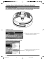
1. Start up the "VN-C655U Setup Tool" and select [Alarm].
1
2
3
4
34
C655(B)_p23-39
34
05.3.16, 1:22 PM
2. Click the [Other Triggers] tab on the [Alarm Setting] screen.
5
6
7
4
3. When setting is complete, click
followed by
.
4. Click the [Alarm Output] tab on the [Alarm Setting] screen.
8
9
4
5. When setting is complete, click
followed by
.
35
C655(B)_p23-39
35
05.3.16, 1:22 PM
Settings (Step 2 Network Settings)
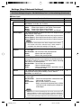
2-4 Other Settings Using the "VN-C655U Setup Tool" (3. Alarm Setting) (Continued)
Alarm Input
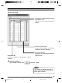
Item
1 Alarm 1/Alarm 2
Mode
Detect Mode
Alarm Output
Function/Set Value
Initial Value
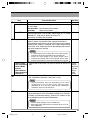
This section describes setting procedures for alarm input.
—
Not Available
For selecting whether to enable or disable the input signals.
Set Values : Available, Not Available
Make
For selecting the method for detecting input signals.
Make : Detect input signals at the "Make" contact point.
Break : Detect input signals during "Break".
Toggle : Detect input signals at both "Make" and "Break".
For selecting whether to output from the alarm output terminal Not Available
when there is alarm input.
Not Available : Do not output from the alarm output terminal.
Alarm Output 1 : Send output from the Alarm Output 1 terminal.
Alarm Output 2 : Send output from the Alarm Output 2 terminal.
Note
• Unless the alarm output in the "Alarm Output" tab is enabled,
this function will not be activated even if alarm output is
selected in the alarm input settings. (☞ Page 39)
Go to a preset
position
Return Mode
Interval
Black & White
For setting whether to move to the preset position when there Not Available
is alarm input.
Not Available : Do not move to the preset position.
Home
: Move to the home position.
1 to 99
: Move to the preset position.
For setting whether to return the camera that has moved to the Not Available
preset position upon the alarm input back to the home position.
Use [Return Interval] to set the time interval before returning
the camera to its home position.
Not Available : Do not return to home position.
Return
: Return to home position.
Event
: Return to home position if operation is not in
the manual mode.
0
For setting the time interval before the camera returns to its
home position when [Return Mode] is set to "Return".
Set Value : 0 to 65535 sec
For switching from the Color to Black & White mode when there Not Available
is alarm input.
Not Available : Do not switch between Black & White/Color mode.
Color
: Color mode at all times.
Black & White : Black & White mode at all times.
Auto
: Switch automatically between Black & White
and Color mode according to the brightness
of the object.
Note
• When Auto is selected, switching may fail in some cases due to the
lighting conditions or angle of view. In order to ensure that switching is
properly performed, it is recommended that signals from an external
sensor (sold separately) be input to the alarm terminal of this camera.
36
C655(B)_p23-39
36
05.3.16, 1:22 PM
Item
1 Alarm 1/Alarm 2
Message Packet
Alarm FTP
2 Relay Alarm
Function/Set Value
Initial Value
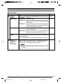
(Continued)
—
For setting whether to send alarm packets to the PC when there Not Available
is alarm input.
Not Available : Do not send alarm packets.
Available
: Send alarm packets.
For operation according to the [Alarm FTP] in the FTP Client Not Available
feature when there is alarm input. Please refer to FTP Client
Settings (☞ Page 47) for details on alarm FTP.
Set Values: Available, Not Available
Set here to enable the relay alarm function, which is activated Not Available
when 2 alarms are received within a preset time interval.
The sequence and time interval for the alarm input can be specified.
When [Alarm Output] is selected, alarm signal output will be
sent to the alarm output terminal on the ceiling mount according to the output port settings.
Notes
• A second alarm input enables this relay alarm function,
and alarm will not be activated for this second input.
• Unless the alarm output in the "Alarm Output" tab is
enabled, this function will not be activated even if alarm
output is selected in the alarm input settings. (☞ Page 39)
• Alarm Output
* Please refer to the [Alarm 1/2] item for details on the set val- *Please
• Go to a preset position ues.
refer to
• Return Mode
the [Alarm
• Interval
1/2] item
• Black & White
for the
• Message Packet
initial
• Alarm FTP
values.
For setting the no. of times alarm notification is to be sent to
1
3 Retry (1 to 3)
the "V.Networks Controller". (Set Value: 1 to 3)
Note
• Alarm notification may fail, depending on the LAN
environment in use. If it fails, set the value for alarm
notification to "3". In this case, alarm by the "V.Networks
Controller" itself is set off only once.
4 List
Press here to display the IP address of the PCs to which an
alarm notification is sent. ("Distribution Address List" Screen)
To delete a distribution address, select the IP address to delete, followed by pressing the Delete button.
—
Notes
• The list allows setting of up to 10 addresses.
• Message packets will not be sent out when there are 11 or
more addresses.
37
C655(B)_p23-39
37
05.3.16, 1:22 PM
Settings (Step 2 Network Settings)
2-4 Other Settings Using the "VN-C655U Setup Tool" (3. Alarm Setting) (Continued)
Other Triggers
Item
5 Preset Position
•
•
•
•
Mode
Alarm Output
Black & White
Message Packet
6 Motion Detection
•
•
•
•
Mode
Alarm Output
Message Packet
Alarm FTP
7 Black & White
• Mode
• Alarm Output
• Go to a preset
position
• Return Mode
• Interval
• Message Packet
Function/Set Value
Initial Value
For performing the following operations by using movement to
—
preset positions as triggers.
* Please refer to the [Alarm 1/2] item for details on the set val- *Please
ues.
refer to
the [Alarm
1/2] item
for the
initial
values.
For setting alarm operations when motion is detected within
—
the area specified in the motion detection settings.
* Please refer to the [Alarm 1/2] item for details on the set val- *Please
ues.
refer to
the [Alarm
1/2] item
for the
initial
values.
For performing the following operations by using switches
—
between the Color and Black & White modes as triggers.
* Please refer to the [Alarm 1/2] item for details on the set val- *Please
ues.
refer to
the [Alarm
1/2] item
Note
for the
• The Black & White alarm may be activated upon
initial
restarting VN-C655.
values.
38
C655(B)_p23-39
38
05.3.16, 1:22 PM
Alarm Output
Function/Set Value
Initial Value
This section describes the setting procedures for alarm output.
Set Values : ON, OFF
Select the alarm output method.
Output OFF : Output alarm signals when the Alarm Output 1
or Alarm Output 2 terminal is connected to the
GND terminal.
Output ON : Output alarm signals when the Alarm Output 1
or Alarm Output 2 terminal and the GND terminal
are disconnected from each other.
Level
: Continue output of alarm signals throughout the
alarm input process.
Momentum : Output alarm signals only at the specified time.
Specify time using the Return Interval item.
OFF
For setting the output interval when the Output Pattern item is
set to Momentum.
This is disabled when the Output Pattern item is set to Level.
—
Upon pressing the Output button, alarm signal output will be
sent from the alarm output terminal on the ceiling mount.
This is used for checking the alarm operation.
—
Item
8 Output 1/
Output 2
Output Value
Pattern
Interval
9 Output 1
force output/
Output 2
force output
—
—
Notes
• Output is disabled when the Output Pattern item is set
to "Level".
39
C655(B)_p23-39
39
05.3.16, 1:22 PM
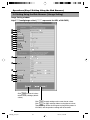
Settings (Step 2 Network Settings)
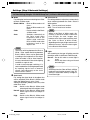
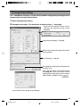
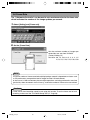
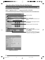
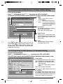
2-4 Other Settings Using the "VN-C655U Setup Tool" (4. Recording Setting)
This function records the image to the memory of VN-C655 when an alarm is activated.
● When an alarm is activated, image recording can be carried out in one of the following two ways.
One way, local recording, saves images to the VN-C655 memory, and the other record images
with [V.Networks Controller] and saves them to the PC hard disc drive, etc. ( ☞ Page 67)
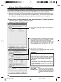
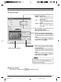
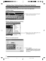
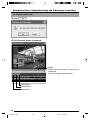
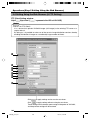
1. Start up the "VN-C655U Setup Tool" and select [Recording]. To make new values
effective, click on [Apply], followed by [OK].
● Setting the [Trigger Recording] screen
1 Select alarm input signal “Trigger” for starting local
recording.
2 To set the frame rate for local recording, select "Change
the Recording Frame Rate during trigger recording",
followed by selecting the frame rate accordingly.
Default frame rate is set at 10 fps. A frame rate of 10
fps for recording will be used when this box is not
checked. (Set values: 30, 15, 10, 8, 6, 5, 4, 3, 2, 1)
● Setting the [Frame Rate] screen
3 For setting the recording time.
This can be set up to 30 seconds before and 60
seconds after the alarm input.
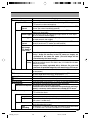
Cautions
● [Before trigger] and [After trigger] values cannot
be set to "0" at the same time.
● Due to the memory capacity of VN-C655, recording
time set for [Before trigger] and [After trigger] may
differ from the actual maximum recording time.
(Example)
If 320x240 (15 fps)/640x480 (5 fps) with a
compression rate of 2, the actual recording time
is 5 to 0 and 30 to 35 seconds, before and after a
trigger respectively.
4 For setting the priority.
Frame Rate
: Priority is given to frame rate settings.
Recording Time : Frame rate is automatically adjusted
such that recording can be performed
according to the specified recording
time.
40
VN-C655(B)_p40-p53
40
05.3.16, 1:23 PM
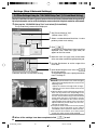
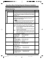
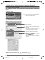
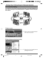
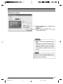
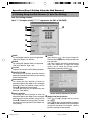
● Setting the [Advance] screen
4 For
setting the recording action when the
memory capacity for recording has become
full. One of the following actions can be
selected. (Internal memory capacity is 8 MB.)
• Stop recording until a free memory space for
recording is created.
• Remove old files that have exceeded a
specific number of days. (If the number of
days is set to "0", files will be deleted starting
with the oldest one.)
Cautions
● When record setting that exceeds the recording
capacity is performed with [Remove old files]
set to "0 days", recorded files will not be retained.
To retain the files, change the value for [Remove
old files] or alter the record settings.
Notes
Recording time
While maximum recording time varies with the recording frame rate and image size, recording over
a specified length of time may not be possible depending on the compression level and object.
Recording files
A trigger-recording file is created each time a trigger occurs. If successive triggers occur over a
continuous period of time, these will be recorded into 1 file.
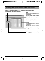
Cautions
Loading local recording images to the PC
Rec files containing local recording images may also be uploaded automatically to the FTP
server. (☞ Page 47, "Rec File")
Perform the following procedure to load local recording images to the PC.
1 Select [Refer to Local Rec.].
2 Select the file to load.
3 Right-click on the selected
file and select
[Download to PC].
To obtain information on whether local recording has started, check the [Trigger] box on the [Recording]
screen, followed by setting [Message] in [Alarm Setting] of the V.Networks Controller. (☞Page 68)
41
VN-C655(B)_p40-p53
41
05.3.16, 1:23 PM
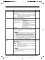
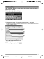
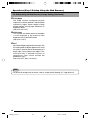
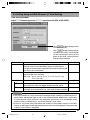
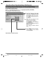
Settings (Step 2 Network Settings)
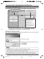
2-4 Other Settings Using the "VN-C655U Setup Tool" (5. Private Mask Setting)
Use the Private Mask function to gray out areas on the screen that are to be excluded during shooting.
Up to 4 private masks can be set for each display screen and a total of 8 private masks for each camera.
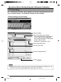
1. Start up the "VN-C655U Setup Tool" and select [Private Mask].
The [Private Mask] screen will be displayed.
(Controller Used for Private Mask Setting)
1
Set [Private Mask] to "ON".
(Default value: "OFF")
2
Select a number between Mask Nos. 1 to 8 to
perform private mask setting.
3
Click
.
A controller for setting the private mask will be
displayed, and a mask area (gray color) will
appear on the live screen.
4
Move the mask area (gray color) to the center
of the area to be masked using the position pad.
5
Use the Size buttons to set the range of the
mask area.
6
Upon determining the mask area, click
to save the setting.
To set multiple mask areas, repeat procedures
from 2 through 6.
Notes
● Even when private mask is set, mask area (gray
color) will not be displayed on the screen in the
following cases.
• When the camera's tilt angle it 40˚ or larger.
• When there are 5 or more mask areas set on
the screen.
● Objects within areas for which private mask has
been set may still be seen, depending on the
orientation of the camera and the zoom position.
As such, ensure that the range of area for which
private mask has been set cannot be seen by
moving the orientation of the camera and the
zoom position upon setting. In the case when
objects within the private mask area are seen,
enlarge the mask area.
● The private mask function will not run properly
during the initial operation of the camera
immediately after its power has been turned on.
● For screens that contain 5 or more preset
masks, the entire screen will be masked.
2. When all the settings have been completed, click
to end.
42
VN-C655(B)_p40-p53
42
05.3.16, 1:23 PM
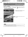
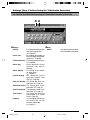
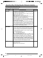
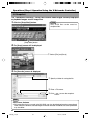
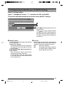
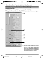
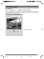
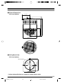
2-4 Other Settings Using the "VN-C655U Setup Tool" (6. Motion Detection Setting)
For setting the motion detection function, which activates the alarm when there is motion
in the camera image. Perform the following procedure to set area for motion detection.
1. Start up the "VN-C655U Setup Tool", select [Alarm Setting] and set [Motion Detection]
to "Available". (☞ Page 38 "Other Trigger")
2. Select [Motion Detect] under [VN-C655 Setup Tool].
1
Select "ON" to turn on the motion detection
feature.
2
Set the detection mode.
Fixed area
Set motion detection only for a specific area.
Select a preset position, followed by clicking
. The Motion Detection Setting
screen will be displayed.
(Set values: Home, Position 1to Position 99)
Free area
Motion detection is activated for all areas.
3
For setting the time interval for defining a
motion.
When there is intensive motion throughout the
entire screen, lengthening the time interval will
help to prevent false detection.
(Set value: 0 to 3)
43
VN-C655(B)_p40-p53
43
05.3.16, 1:23 PM
Settings (Step 2 Network Settings)
2-4 Other Settings Using the "VN-C655U Setup Tool" (6. Motion Detection Setting) (Continued)
3. Perform area setting.
Image of the position that is selected as the Fixed area in 2 of Step 2 will be displayed.
1
Click and drag the mouse to select the
detection area. To cancel the detection area
(displayed in yellow), right-click and drag the
mouse.
Area for which motion is detected will be
displayed in red.
2
For setting the sensitivity level of motion
detection.
Drag towards the right to increase and left
to decrease the sensitivity level.
, area other than that
Upon clicking
selected in 1 will be selected as the motion
detection area and displayed in yellow.
Notes
● The area display position only serves as a guide. Ensure to perform operation check.
● Each screen is divided into 300 (20x15) blocks. Adjust the zoom ratio of the lens such that the
object for which motion is to be detected is at least the size of multiple blocks.
Cautions
● Flickering lights may cause false detections in motion when the camera is connected.
● When brightness varies due to the use of the auto iris function or lighting conditions, this may
be detected as motion. In this case, it is recommended that the detection time be set to a
value other than "0".
● When automatic control is enabled, false detection may occur at the instant when the camera
starts to move. In this case, it is recommended that the detection time be set to a value other
than "0".
● Note that the motion detection function is not designed to prevent theft or fire. It may not
function properly under certain object or setting conditions. We shall not be responsible for
any accident or losses incurred.
44
VN-C655(B)_p40-p53
44
05.3.16, 1:23 PM
2-4 Other Settings Using the "VN-C655U Setup Tool" (7. Web)
A designated html file can be set as the default page for the web browser using this setting.
1. Start up the "VN-C655U Setup Tool" and select [Web].
Specify settings for viewing using the web
browser. When "Disable" is checked, viewing of
images from other PCs will be disabled.
Set the use of a default HTTP page.
Specify the html file to be used as the default
page when the [Available] box is checked.
Set the port number.
The proxy server may cache cgi on some rare
occasions, and setting may not be successfully
performed. In this case, check "No Cache".
Cautions
● It is possible to increase the security level by setting the HTTP server port number of this
camera to a value other than the default value of 80 (value can be set between 1 to 65535.
However, 21 and 554 cannot be used).
Upon changing the HTTP port number, access from the web browser by entering http://
192.168.0.2:12345 or http://192.168.0.2:12345/index.html (when the port number is changed
to 12345). If you have lost track of the HTTP port number, check using the setup tool provided.
● Default page refers to the page displayed upon specifying the IP address such as http://
192.168.0.2 at the web browser.
Even when this feature is set to "Enabled", an error message indicating "404: Not Found" will
be displayed when http://192.168.0.2 is entered if the html file specified here does not exist.
Be sure to enter correctly.
● Displaying still images uploaded to the /user folder
Still images in the /user folder can be displayed by creating a web page containing the following:
<IMG SRC ="/user/xxxxx">
(xxxxx refers to the file name of the still image)
45
VN-C655(B)_p40-p53
45
05.3.16, 1:23 PM
Settings (Step 2 Network Settings)
2-4 Other Settings Using the "VN-C655U Setup Tool" (8. FTP Server)
HTML pages or gif and jpeg images can be uploaded to this camera by using the
FTP Client software.
1. Start up the "VN-C655U Setup Tool" and select [FTP Server].
Set the FTP Server Function to "ON" or "OFF".
Notes
● The FTP user name is fixed as "Administrator". Use the administrator level password as the
FTP password.
● About 256 KB is allocated as the FTP's user area.
● All uploaded files will be placed under the /user folder.
Access from the web browser is possible by entering http://192.168.0.2/user/
aaa.html.(192.168.0.2 is the IP address for this camera when referring to aaa.html that is
stored in the FTP.)
● Folders cannot be created on the FTP server of this camera. Only uploading, deletion and
renaming of files are possible.
46
VN-C655(B)_p40-p53
46
05.3.16, 1:23 PM
2-4 Other Settings Using the "VN-C655U Setup Tool" (9. FTP Client Setting)
VN-C655 is equipped with a "FTP Client" feature that uploads still images to the
existing FTP server on a regular interval. This feature enables simultaneous image
monitoring by many clients (from many locations).
1. Start up the "VN-C655U Setup Tool" and select [FTP Setting].
The [FTP Setting] screen will be displayed.
1
Continuous FTP
Check [Available] to enable the FTP
feature.
2
8
Trigger FTP
• Rec File
*.rec files containing local recording
images will be uploaded automatically
to the FTP server.
• Alarm FTP
For uploading still images (JPEG) to
the FTP server when there is an
alarm input.
For detailed settings, refer to the
alarm FTP upload settings.
(☞ Page 48)
9
Notes
1
2
3
4
5
6
7
● Uploading starts automatically
when a rec file is created.
● To delete a rec file, following the
[Lower Memory Size] setting on
the recording setting screen.
● When there is not enough free
space in the built-in memory of VNC655 to create a Rec file, the [Rec
file] setting will not be executed. To
enable the [Rec file] setting, it is
recommended that the [Remove
old files] setting under [Lower
Memory Size] setting is set to [0].
● Uploading of still images will
temporarily stop when uploading
of Rec file starts.
0
!
47
VN-C655(B)_p40-p53
47
05.3.16, 1:23 PM
Settings (Step 2 Network Settings)
2-4 Other Settings Using the "VN-C655U Setup Tool" (9. FTP Client Setting) (Continued)
3
4
Username
Enter the user name to use for verification with
the FTP server. It can be set as "anonymous".
Password
Enter the password to use for verification with
the FTP Server. Characters entered are
displayed as " * ".
Note
To resume operation, set 1 [Continous
FTP] to "Available".
0
Filename
*.jpg : Check this item to upload file with the
name that appears in the position
indicated as " * ".
5
FTP Serverv IP Address
Enter the IP address of the FTP server at the
upload destination.
6
FTP Port
Enter the FTP port number at the upload
destination.
This is normally set to "21".
Files are always overwritten with the latest
ones and therefore only 1 image file will
be stored in the FTP server.
FTP Folder
Enter the folder name on the FTP server at
the upload destination.
Images will be uploaded to the default folder
when this is left blank.
Timestamp : Upload the time of the internal
clock in VN-C655 as the file
name.
Upload Interval
Specify the upload interval at which images
are uploaded to the FTP server.
(Set value: 0 to 65535)
If "Disconnect every time" is selected,
connection with the FTP server will be cut off
upon uploading of each image.
● Ensure to set to the correct time on the
Time Setting screen.
● All image files uploaded are stored in
the FTP server.
7
8
9
Error recovery
(Connection error)
Specify a recovery action when an error
occurred with the TCP connection or FTP
verification of VN-C655.
Retry forever : Recovery attempt is repeated
until the power for VN-C655
is turned off.
* mins. Retry : Recovery attempt is repeated
for a specified duration.
Set value (*) 1 to 600 mins
(Transfer error)
Specify a recovery action upon occurrence of
a file transfer error while uploading the images.
Disable FTP : Disable the FTP function
automatically.
Note
Notes
!
Alarm FTP Upload Setting
Specify the method for uploading still images
via the alarm FTP.
Upload Interval : Set the time interval for
uploading JPEG images
to the FTP server when
there is an alarm input.
Set value: 0 to 60 seconds
Before trigger : Set the time interval for
uploading images before
an alarm input.
Set value: 0 to 5 seconds
before trigger
After trigger
: Set the time interval for
uploading images after
an alarm input.
Set value: 0 to 60 seconds
after trigger
48
VN-C655(B)_p40-p53
48
05.3.16, 1:23 PM
2-4 Other Settings Using the "VN-C655U Setup Tool" (10. Black & White Setting)
1. Start up the "VN-C655U Setup Tool" and select [B & W].
The [Black & White] screen will be displayed.
1
2
3
4
Click
.
The [Trigger Setting] screen will be displayed.
Set the [Time Trigger] for switching the Black
& White mode at the specified time.
Time1/Time2
Mode
Black and White
: Switches to the Black & White
mode upon reaching the
specified time.
<Trigger Setting Screen>
Color
: Switches to the Color mode upon
reaching the specified time.
Auto
: Switches automatically between
the Black & White and Color
modes according to the brightness
upon reaching the specified time.
Time
Time at which the selected "Mode" will be
activated.
2. When all the settings have been completed, click
to end.
49
VN-C655(B)_p40-p53
49
05.3.16, 1:23 PM
Settings (Step 2 Network Settings)
2-4 Other Settings Using the "VN-C655U Setup Tool" (10. Black & White Setting) (Continued)
1
Mode
For setting the function on switching from Color
to Black & White mode.
Black & White : Black & White mode at all
times. :
Black & White mode at all
times.
Color
: Do not switch to the Black
& White mode.
Auto
: Switches automatically to
the Color mode when
brightness level of the
object is high, and to the
Black & White mode when
brightness level of the
object is low.
3
One Push AF
For setting whether to adjust focus automatically
when switching between the Color / Black &
White modes.
ON : Turn on auto focus function.
OFF : Turn off auto focus function.
Note
When in the Black & White mode, this
camera is sensitive to both visible and
near-IR light. As such, images may
become out of focus upon switching from
the Color to Black & White mode,
depending on the type of light source used.
When this occurs, adjust the focus again
in the Black & White mode.
Note
To ensure switching between the Black &
White / Color modes Switching between
Black & White / Color may be performed
according to the brightness of the object
when the mode is set to Auto. However,
this may sometimes fail due to the lighting
condition or angle of view.
In order to ensure proper switching, it is
recommended that switching be performed
by inputting signals from an external
sensor (sold separately) to the alarm
terminal of this camera.
2
Auto Level
For setting the signal level of the object that
will be switched to the Black & White mode
when the [Mode] item is set to "Auto".
Setting is disabled if [Mode] is set to any value
other than "Auto".
Low : Switch to the Black & White mode
when signal level of the object is low.
Normal: Switch to the Black & White mode
when signal level of the object is
normal.
High : Switch to the Black & White mode
when signal level of the object is
high.
4
Light
Set according to the type of lighting used for
the object when in the Black & White mode.
Normal : Set to this when a normal light is
used.
IR
: Set to this when using an infrared
emission light.
Note
Switching from the Color to Black & White
mode may not function correctly if the "IR"
setting is used under ordinary sunlight or
fluorescent light.
50
VN-C655(B)_p40-p53
50
05.3.16, 1:23 PM
2-4 Other Settings Using the "VN-C655U Setup Tool" (11. Time Setting)
This section describes how to set the standard time for VN-C655. NTP can also be
used for this function.
1. Start up the "VN-C655U Setup Tool" and select [Time].
There are 2 methods of setting, depending on whether NTP is to be used.
When NTP is not used
1 Set the date and time.
2 Allows reference of PC time.
When NTP is used
1 Enter the IP address of the NTP server to be used.
2 Set the time zone.
3 Set the time interval for acquiring the current
time from the NTP server.
Notes
● When using NTP, an NTP server will be required.
● When the time is changed during local recording, local recording time may not be correctly
counted and recording for the specified number of seconds may not be obtained.
● Even upon selecting the NTP server and applying the settings, you will have to set the time
again when the power is turned on if the NTP server cannot be used.
● The NTP server function is enabled by default upon standard installation of Windows XP
Home Edition and Windows XP Professional.
● For Windows 2000, perform the following setting to enable the NTP server function.
1. Set the following registry value to "1". (Default: "0")
HKEY_LOCAL_MACHINE\SYSTEM\CurrentControlSet\Services\W32Time\Parameters\LocalNTP
Note that registry editing is a highly risky operation.
Editing operations shall be performed at your own risk. Please store backups of the
registry as a safety measure. JVC shall not be held liable for any accident that arise
from this operation.
2. Restart the Windows Time Service (= Stop and start again).
Open the [Properties] for Windows Time Service from [Services] under [Administrative
Tools].
51
VN-C655(B)_p40-p53
51
05.3.16, 1:23 PM
Settings (Step 2 Network Settings)
2-4 Other Settings Using the "VN-C655U Setup Tool" (12. Memory Information)
It is possible to check the memory capacity of VN-C655.
1. Start up the "VN-C655U Setup Tool" and select [Memory Info].
1 Check the available memory space.
(The built-in memory capacity of this
camera is about 8000 KB.)
2-5 Registering Connected Camera Using the "V.Networks Controller"
The connected camera can be registered with the installed "V.Networks Controller".
1. Select [Start] † [Programs] † [V. NETWORKS] †
[V.Networks Controller] to
start up the "V.Networks Controller".
2. Select [File] and [New].
3. The [New] screen will be displayed.
1 Enter the [IP Address].
Note
In a DHCP environment, enter the IP
address that is assigned to this camera by
the DHCP server.
2
Enter the [V.Networks Name]. Do so by using
a name convenient for subsequent selection,
such as the installation location or number.
(1 to 40 characters)
3
A folder with the name entered in 2 will be
created inside the folder specified here, and
recorded files will be stored here.
Select the mode for acquiring images.
Normal :
Client will send requests for each image to
VN-C655.
Set to Normal when using a narrow
bandwidth network.
High Speed:
Images will be automatically sent from VNC655 at the specified frame rate. A
maximum transmission rate of 30 fps is
possible for 640 x 480 images.
When sending out images to multiple
clients at the same time, however,
transmission at a rate of 30 fps for 640 x
480 images will not be possible.
4
52
VN-C655(B)_p40-p53
52
05.3.16, 1:23 PM
Notes
● Images are divided into IP fragments when set to "High Speed".
● Images will be sent at the frame rate set at VN-C655. When setting the frame rate to "High Speed",
do so upon ensuring that this does not impose excessive burden on the network. (☞ Page 65)
● Do not set to high speed for narrow bandwidth networks.
● Maximum data transmission capacity is 8 Mbps. A maximum rate of 30 fps may not be possible
for 640 x 480 images depending on the image size.
● The MTU (Maximum Transmission Unit) sizes during image acquisition are as follows.
Transmission Mode
Normal
MTU Size (Bytes)
1430 Bytes
High Speed
1500 Bytes
4. Connect to VN-C655.
Notes
To connect to a VN-C655 for which DHCP
setting is possible, either one of the following
environments will be required.
• Environment where no DHCP server
exists.
• Environment with a DHCP server that
clearly defines the IP and MAC addresses
assigned to VN-C655.
53
VN-C655(B)_p40-p53
53
05.3.16, 1:24 PM
Settings (Step 3 Setting Using the V.Networks Controller)
3-1 Starting Up V.Networks Controller
The installed "V.Networks Controller" can be used to monitor camera images.
In addition, recording/playback operations and setting of frame rate for camera
images are also possible.
1. Select [Start] † [Programs] † [V. NETWORKS] †
[V.Networks Controller] to
start up the "V.Networks Controller".
1 Select the camera to connect to from the
pull-down menu for the camera.
2 Live
2
images from the camera wil be
displayed.
Notes
● Enter the correct password if a password has been set.
● This controller can be connected to VN-C1, VN-C2, VN-C3, VN-C30 (JPEG only), VN-A1, VNC10 (JPEG and MPEG) and VN-C625 as well VN-C655.
54
C655(B)_p54-p77
54
05.3.16, 1:29 PM
3-2 Features that Allow Setting Using the V.Networks Controller
The V.Networks Controller can be used to perform settings for image size and alarm.
1
2 3
1File
New
: Creates a new file if the camera
is connected for the first time.
Delete
: Deletes a file.
Motion Detection Standby
: Select the camera for which
the Motion Detection Standby
function is to be enabled.
Exit
: Exits the controller.
2View
Image Size
: Sets the image display size.
JPEG : 640 x 480
320 x 240
Upside Down: Displays the image inversely.
3Control (C)
Auto Pan
: Select this item and click to
start the Auto Pan operation.
Auto Patrol (Mode1 to Mode 3)
: Select a mode for this item and
click to start the Auto Patrol
operation for the selected
mode.
Auto Trace : Select this item and click to
start the Auto Trace operation.
Auto Pan Stop
: Stops the Auto Pan operation.
Auto Patrol Stop
: Stops the Auto Patrol operation.
Auto Trace Stop
: Stops the Auto Trace operation.
Notes
● The following setting are disabled during
Auto Pan:
• Auto Pan Setting
• Auto Patrol Setting
• Auto Trace Setting
• Preset Position Setting
• Pan Control
● The following setting are disabled during
Auto Patrol:
• Auto Pan Setting
• Auto Patrol Setting
• Auto Trace Setting
• Preset Position Setting
• Pan/Tilt Control
• Zoom Control
● The following setting are disabled during
Auto Trace:
• Auto Pan Setting
• Auto Patrol Setting
• Auto Trace Setting
• Preset Position Setting
• Pan/Tilt Control
• Zoom Control
• Focus Control
55
C655(B)_p54-p77
55
05.3.16, 1:29 PM
Settings (Step 3 Setting Using the V.Networks Controller)
3-2 Features that Allow Setting Using the V.Networks Controller (Continued)
4 5
5Help
4Setting
Quality
: For setting the compression
rate and image quality.
(☞ Page 59)
Frame rate
: For setting the number of
camera images to send per
second. (☞ Page 65)
Position Memory : For setting preset positions.
(☞ Page 66)
Alarm Reg
: Alarm operation will be
enabled if this item is
checked.
Alarm Setting
: For setting alarm actions
for each alarm.
(☞ Page 67)
Pan/Tilt Setting : For setting the Pan/Tilt
operation (speed, Auto
Flip). (☞ Page 69)
Auto Pan Setting : For setting the Auto Pan
operation. (☞ Page 70)
Auto Patrol Setting: For setting Auto Patrol
operation. (☞ Page 72)
Auto Trace Setting : For setting the Auto Trace
operation. (☞ Page 74)
Time Stamp
: For setting the date and
time display of a stored
file.(☞ Page 76)
Property
: For changing information
of cameras that are not
currently connected.
(☞ Page 77)
About
: For checking the version of
the V.Networks Controller.
56
C655(B)_p54-p77
56
05.3.16, 1:29 PM
3-3 Motion Detection Standby
The "Motion Detection Standby" function enables automatic connection upon
receiving notifications on detected motion from VN-C655 when the V.Networks
Controller has been started up.
1. Select [File] and [Motion Detection Standby].
2. Select a camera.
1 Select the camera for which the Motion
Detection Standby function is to be
enabled.
1 Click
3. Click
.
.
57
C655(B)_p54-p77
57
05.3.16, 1:29 PM
Operations (Step 3 Setting Using the V.Networks Controller)
3-4 Image Size and Inversion
The "V.Networks Controller" can be used to set the size of the motion image window
as well as to invert an image.
1. Select [View].
2. Specify [Image Size] and [Upside Down] settings.
Notes
● Setting to the Fine mode enables
display of image details.
Images of moving objects shot in this
mode may be blurred, but this is not a
malfunction.
● Fine mode can only be used with the
640 x 480 resolution.
Click
.
Notes
Right-click on the motion image window to
change the settings.
Set the image size.
• VN-C655 does not support the 160 x 120
setting.
Click to adjust focus automatically.
Displays the MAC address, IP address,
model and firmware version.
When
is checked, a grid for the motion
detection area will appear and the detection
area will be displayed in red.
58
C655(B)_p54-p77
58
05.3.16, 1:29 PM
3-5 Image Quality Setting
The "V.Networks Controller" can be used to perform image quality settings such as
compression level and white balance.
1. Select [Setting] and [Quality].
2. Change the set values. (For description of each function, ☞ next page)
* When the [Distribution control ON] is
selected, the following screen will be
displayed.
Image Quality Setting (☞ Page 60)
Resets all set values on image quality to their
factory settings.
Lens Setting (☞ Page 64)
For setting the image quality during Auto Pan
and Auto Trace.
to display a confirmation screen
Click
containing the current set values. Perform
setting using "Image Quality" on this screen.
When setting is complete, click
.
<Auto Pan/Auto Trace Image Quality Setting>
59
C655(B)_p54-p77
59
05.3.16, 1:29 PM
Operations (Step 3 Setting Using the V.Networks Controller)
3-5 Image Quality Setting (Continued)
Image Quality Setting
Item
Function/Set Value
Initial Value
Distribution Control Set the maximum transmission control.
OFF
Setting of compression level is possible when this is set to "OFF",
and images will be sent out at the specified compression level.
The smaller the value, the lower the compression level and hence
a higher image quality. However, data volume will also increase.
Set Value: 1 to 7
Setting of bit rate is possible when this is set to "ON", and the
ON
compression level of images will be automatically adjusted according to the specified bit rate before they are sent out.
Set value: 32 kbps to 8 Mbps
OFF
2
—
Note
• It will be necessary to establish connection again upon
setting to enable display at the correct frame rate.
WB
R-B
Mg-G
Color Level
Enhance Level
Pedestal Level
Determines the setting of the white balance adjustment
feature.White balance can be adjusted for lighting conditions
within a color temperature range of 2,300 K to 10,000 K.
ATW : Auto-Tracking White Balance mode. Adjusts the white
balance automatically according to the color temperature of the lighting.
During ATW setting, hue adjustment for the R-gain and
B-gain items will be disabled.
AWC : If AWC is selected from the pull-down menu, the Auto
White Control mode will be activated for white balance
adjustment. Switching from the ATW to AWC mode will
take at least 15 seconds.
Adjusts the phases of R (Red) and B (Blue) under AWC mode.
To enhance blue
: Decrease the value.
To enhance red
: Increase the value.
Setting values
: 0 to 100
Adjusts the phases of M (Magenta) and G (Green) under AWC
mode.
To enhance green
: Decrease the value.
To enhance magenta : Increase the value.
Setting values
: 0 to 100
Adjusts the color level of video signals.
To lighten the color † Decrease the value
To darken the color † Increase the value
Set value: -5 to 5
Sets the contour enhancement which controls the sharpness
of video signals.
To soften the picture
† Decrease the value
To sharpen the picture † Increase the value
Set value: -5 to 5
Sets the pedestal level (black level) of video signals.
To darken the picture † Decrease the value
To brighten the picture † Increase the value
Set value: -5 to 5
60
C655(B)_p54-p77
60
05.3.16, 1:29 PM
ATW
56
30
0
0
0
Item
Function/Set Value
Initial Value
Auto Black Control
Use this function when darker parts of a picture are unclear
even after the gain has been increased using the AGC (Auto
Gain Control).
ON
: When the black level of the video signal is low, the
pedestal level is increased automatically in order to
improve the clarity of the darker parts.
OFF : Turns this function off.
Sets the method of exposure detection according to ratio between the average and peak values.
• Large Average value : Use this setting when areas other than
those highlighted are dark and unclear.
(Example: 10:0)
• Large Peak value : Use this setting when halation occurs
at the highlighted areas.
Use this setting when areas other than
those highlighted are dark and unclear.
(Example: 5:5)
Set value
: 10:0, 9:1, 8:2, 7:3, 6:4, 5:5
Sets the speed of the electronic shutter.
Set value : 1/60, 1/100, 1/250, 1/500, 1/1000, 1/2000, 1/4000,
1/10000
OFF
Average : Peak
Shutter
8:2
1/60
Notes
• To reduce flickering that occurs under fluorescent
lighting, set the shutter speed to 1/100 if your local power
supply frequency is 50 Hz, and to 1/60 if it is 60 Hz.
• The higher the shutter speed, the more prominent will
be the smear phenomenon. This is a phenomenon that
is characteristic of CCDs, whereby white stripes appear
at the top and bottom of a bright light source.
AGC
Sets the maximum gain of the AGC (Auto Gain Control), which
electronically increases the gain when the object is under low
light conditions.
OFF : Disable AGC.
10 dB : Increase gain by a maximum of 10 dB according to
the brightness of the object.
20 dB : Increase gain by a maximum of 20 dB according to
the brightness of the object.
10 dB
Note
• The screen may appear grainy at dark places when the
gain level is increased.
61
C655(B)_p54-p77
61
05.3.16, 1:29 PM
Operations (Step 3 Setting Using the V.Networks Controller)
3-5 Image Quality Setting (Continued)
Image Quality Setting (Continued)
Item
Function/Set Value
Initial Value
Sense Up
This function is used to increase the sensitivity by extending
the exposure time. Increasing this value slows the shutter speed
and motion may appear unnatural.
When the item "SHUTTER" is set to "1/250" or more, the
SENSE UP item does not work.
Setting values: OFF, x2, x4, x8, x16, x24, x32
• When SENSE UP is activated, the picture may become rough
and whitish, and subject to white blemishes.
• When the setting of the "SENSE UP" function is not OFF,
flicker may appear on the screen under fluorescent light or
mercury lamps. This is due to the principles of the SENSE
UP, and is not a malfunction.
• There may be cases where flicker can not be reduced even
under the following conditions: 1) Shutter speed is set at 1/100
in areas where the commercial electric current frequency is 60
Hz. 2) The shutter speed is set at 1/60 in areas where the commercial electric current frequency is 50 Hz.
OFF
ExDR Mode
The ExDR function synthesizes pictures captured at a shutter
speed of 1/100 and those captured at higher shutter speeds to
help monitor objects having large differences in brightness levels.
When the "SHUTTER" function is set to "1/250" or a higher,
this function does not work.
OFF : Turns the ExDR function off.
ON : Turns the ExDR function on.
• When the ExDR function is on, flicker may appear on the
screen under fluorescent light or mercury lamps. This is due
to the principles of the ExDR, and is not a malfunction.
• There may be cases where flicker cannot be reduced even
under the following conditions: 1) Shutter speed is set at 1/
100 in areas where the commercial electric current frequency
is 60 Hz. 2) The shutter speed is set at 1/60 in areas where
the commercial electric current frequency is 50 Hz.
OFF
ExDR Level
This function sets which section of the object is to be displayed
in the easiest-to-view
brightness level in the ExDR mode.
0
62
C655(B)_p54-p77
62
05.3.16, 1:29 PM
Item
Function/Set Value
Initial Value
ExDR Level
(Continued)
To make a low-light section of the object easy to view: Increase
the level.
To make a highlighted section of the object easy to view: Decrease the level.
Setting values : -5 to 5
• When the difference in brightness between objects is large,
the picture may not change even when the ExDR LEVEL is
varied. This is due to the characteristics of the camera and is
not a malfunction.
• When the item "SHUTTER" is set to 1/250 or higher,the settings to the item "ExDR LEVEL" cannot be carried out.
• When the item "ExDR MODE" is set to OFF, the settings for
the item "ExDR LEVEL" cannot be carried out.
0
V.Sharpness
This function sets sharpness in the vertical direction of the NORMAL
image.
NORMAL : Normal sharpness.
HIGH
: High sharpness.
The following phenomena may be observed when HIGH is
selected. This is not a malfunction.
* Horizontal stripes are observed on bright objects.
* Vague horizontal stripes are observed under low light conditions.
BLC
Sets of area of back light compensation. Use this function when
the object appears dark (under auto iris control) because of
the presence of a bright light source behind it. This function
make it possible to place the unnecessary light source outside
the photometry area.
OFF
: The backlight compensation function
does not work.
ARER 1 to AREA 4 : Select one of the four types.
OFF
Photometry Area Photometry Area
Photometry
Area
OFF
Photometry
Area
Area 1
Area 2
Area 3
Photometry
Area
Area 4
When the item "ExDR MODE" is set to ON, the item "BLC" is
set to OFF. Under this condition, the settings to the item "BLC"
cannot be varied.
63
C655(B)_p54-p77
63
05.3.16, 1:29 PM
Operations (Step 3 Setting Using the V.Networks Controller)
3-5 Image Quality Setting (Continued)
Lens
Item
Function/Set Value
Initial Value
Iris
Adjust the brightness of lens.
A smaller value makes images darker, closing the iris.
Auto
: Adjusts iris automatically.
Auto + : Adjusts iris automatically to a level brighter than
the default state.
Auto – : Adjusts iris automatically to a level darker than the
default state.
Manual : Adjusts iris manually.
Auto
Focus
Easy AF
Adjust focus.
Move the slider to the left to focus far object while moving the
slider to the right to focus near object.
Easy AF : Focus will be adjusted automatically when Pan/Tilt
and Zoom are operated on the camera.
Manual : Adjusts the focus manually.
Zoom
Perform Zoom operation.
The object enlarges when zoomed towards the Wide end, and
reduces when zoomed towards the Tele end.
When the zoom lens is set toward TELE, optical zooming is
activated first and electronic zooming second. This function
sets the maximum zoom ratio of the electronic zooming.
Setting values : x1, x2, x4, x6, x8, x10.
Note
● Note Picture quality deteriorates under electronic zooming as
it is accompanied by digital image processing.
● An increase in the electronic zooming ratio may deviate the
center of the image slightly toward the top left. This is due to
the camera properties and is not a malfunction.
● Continuous operation from optical zooming to electronic zooming is not available. When optical zooming reaches the TELE
end, press the TELE button again.
● During digital zoom, the PAN/TILT Position Indicator
(☞Page 73) lights up in yellow color.
ALC Priority
When an object is dark, this functions sets whether priority
during monitoring is placed on maintaining the motion of the
camera or on picture quality.
Motion : Motion of the camera is given priority. When an object is dark, the AGC function is prioritized. This setting is suitable when objects are characterized by
quick motion.
Picture : Picture quality is given priority. When an object is
dark, the SENSE Up function is prioritized. This setting is suitable when picture quality is important.
When the "AGC " and "SENSE UP" functions are both set to
"OFF", this function does not work .
64
C655(B)_p54-p77
64
05.3.16, 1:29 PM
Motion
3-6 Frame Rate
The "V.Networks Controller" can be used to set a maximum value for the frame rate,
which indicates the number of live image updates per second.
1. Select [Setting] and [Frame rate].
2. Set the [Frame Rate].
Set the maximum number of images per
second that are sent from VN-C655.
(Factory Setting: 15)
Set value : 30, 15, 10, 8, 6, 5, 4, 3, 2, 1,1/
2,1/3, 1/5, 1/10, 1/15, 1/20, 1/30
Notes
The actual number of frames received and displayed per second is dependent on factors such
as PC performance, compression level of images and the LAN environment.
In the case of a LAN environment where multiple operations are being performed at one time
(particularly when the network traffic is heavy), reduce the number of frames to be transmitted.
Cautions
Frame rate for local recording cannot be set using this function. To set the frame rate for local
recording, make use of the "VN-C655U Setup Tool" (☞ Page 40).
65
C655(B)_p54-p77
65
05.3.16, 1:29 PM
Settings (Step 3 Setting Using the V.Networks Controller)
3-7 Preset Position Setting
The "V.Networks Controller" can be used to set the preset position for the connected
camera.
1. Select a camera.
1 Select a camera for setting from the pulldown menu for the camera.
2. Select [Setting] and [Position Memory].
1 Select a position.
2 The title of the current position will be
displayed.
Enter here to change the title. (Up to 32
single-byte characters (32 bytes))
3 Adjust the angle of view and zoom.
4 Adjust the image quality.
to display the Image
Click
Quality Setting screen.
(For details on set values, ☞ Page 62 to
Page 64)
<Image Quality Setting Screen>
3. When setting is complete, click
followed by
.
66
C655(B)_p54-p77
66
05.3.16, 1:29 PM
3-8 Alarm Setting
The "V.Networks Controller" can be used to set the action to be taken when an
alarm signal is received.
1. Select [Setting] and [Alarm Setting].
2. Change the set values. (For description of each function, ☞ next page)
Setting may be performed for the [Motion Detection], [Alarm 1], [Alarm 2], [Relay Alarm], [Preset
Position] and [Black & White].
1
2
3
4
(Setting of 1 and 2 are disabled when in the
Relay Alarm mode.)
3. When setting is complete, click
.
67
C655(B)_p54-p77
67
05.3.16, 1:29 PM
Settings (Step 3 Setting Using the V.Networks Controller)
3-8 Alarm Setting (Continued)
1
2
Message
Message entered in the textbox will be
displayed when there is an alarm input.
(Up to 100 single-byte characters)
3 Playing wave file
Plays back a designated Wave file when there
is an alarm input. Click the [Browse] button to
specify a file.
Note
Recording
Starts recording when there is an alarm input.
Non-stop : Recording continues until the Stop
button is pressed.
1 minute : Recording stops after 1 minute.
Notes
Alarm actions may be delayed due to PC
performance if a large Wave file (.wav) is
selected.
4 Execute application file
● The [1 minute] mode is used for conserving
hard disk space.
● In this mode, recording stops after 1 minute
even if recording has already started
before the alarm input.
Executes a designated program when there
is an alarm input. Click the [Browse] button to
specify a program.
Notes
Alarm Operation
The following settings are required for the operation of the set alarm.
1. [Alarm Reg] is checked. This item is located under the [Setting] menu of the "V. Networks
Controller". (☞ Page 56)
2. All alarm settings in the [Alarm Setting] of the "VN-C655U Setup Tool" are enabled. (☞ Page 34)
Relay Alarm
When the Relay Alarm function is enabled, subsequent alarms will not be activated.
68
C655(B)_p54-p77
68
05.3.16, 1:29 PM
3-9 Pan/Tilt Setting
The "V.Networks Controller" can be used to perform pan/tilt settings.
1. Select [Setting] and [Pan/Tilt Setting].
2. Perform Pan/Tilt settings.
Pan/Tilt Speed
Sets the speed of movement when Angle Step is
set to "0".
Variable:
Alters the pan/tilt speed automatically according
to the zoom of the lens.
The speed lowers when the zoom position is
set to the Tele-end, and increases when set to
the Wide-end.
Speed 1 to Speed 8:
Sets the Pan/Tilt speed. The larger the value,
the higher will be the pan/tilt speed.
Auto Flip
Inverts images on the screen according to the
camera angle. Set this function when shooting an
object that passes beneath the camera.
OFF : Auto Flip is disabled.
ON
: The image rotates 180˚ horizontally and
stops when the object comes directly
beneath the camera.
3. Click
.
69
C655(B)_p54-p77
69
05.3.16, 1:29 PM
Settings (Step 3 Setting Using the V.Networks Controller)
3-10 Auto Pan Setting
The "V.Networks Controller" can be used to set the Auto Pan operation, which moves
the camera from a preset position horizontally at a constant speed.
Return
An
ti-c
loc
kw
ise
ckw
Clo
ise
1. Select a camera.
1 Select the camera for setting from the
pull-down menu for the camera.
2. Select [Setting] and [Auto Pan Setting].
1 Select [Auto Pan Setting] from the
[Setting] pull-down menu.
70
C655(B)_p54-p77
70
05.3.16, 1:29 PM
3. Perform setting.
1 Set Auto Pan operation using the [Action
Mode] pull-down menu.
• Right
: Rotates horizontally in the
clockwise direction from the
start position.
• Left
: Rotates horizontally in the anticlockwise direction from the start
position.
• Return : Moves continuously between the
start and return positions
horizontally.
2 Set the speed of operation from the
[Speed] pull-down menu.
(Set value: High, Normal, Low)
3 Set the start position of the operation.
Set the start position using the position
setting control panel, followed by clicking
.
If Pan/Tilt is operated after setting the
to move the
start position, click
camera to its start position.
4 Set the return position of the operation.
(This can be specified only when [Mode]
is set to "Return".)
Set the return position using the position
setting control panel, followed by clicking
.
If Pan/Tilt is operated after setting the
to move the
return position, click
camera to its start position.
<Position Setting Controller>
Note
For starting and stopping operations of
Auto Pan, Auto Patrol and Auto Trace,
please refer to Page 55.
4. Close the window.
When setting is complete, click
to close the window.
71
C655(B)_p54-p77
71
05.3.16, 1:29 PM
Settings (Step 3 Setting Using the V.Networks Controller)
3-11 Auto Patrol Setting
The camera can be moved to multiple positions based on the preset sequence and
time. Use this setting to view specified positions in sequence. Perform setting for
each camera.
1. Select a camera.
1 Select a camera for setting from the pulldown menu for the camera.
2. Select [Setting] and [Auto Patrol Setting].
1 Select [Auto Patrol Setting] from the
[Setting] pull-down menu.
72
C655(B)_p54-p77
72
05.3.16, 1:29 PM
3. Perform setting.
1 Set the mode. Setting can be performed
from Modes 1 to 3.
Click the tab of the respective mode for
setting.
2 Set the Position Number.
For each Patrol Number, set a Position
Number to move to in sequence.
3 Set the time interval.
Auto Patrol No.
Auto Patrol operates in the sequence of these
numbers.
Set the time for displaying each position
set in 2.
(Unit: seconds)
4. Close the window.
When setting is complete, click
to close the window.
Note
For starting and stopping operations of
Auto Pan, Auto Patrol and Auto Trace,
please refer to Page 55.
73
C655(B)_p54-p77
73
05.3.16, 1:29 PM
Settings (Step 3 Setting Using the V.Networks Controller)
3-12 Auto Trace Setting
Details of manual camera operations can be stored and reproduced.
1. Select a camera.
1 Select a camera for setting from the pulldown menu for the camera.
2. Select [Setting] and [Auto Trace Setting].
1 Select [Auto Trace Setting] from the
[Setting] pull-down menu.
3. Start to memorize operation.
1 Click
.
Memorization of Auto Trace will start and
subsequent pan/tilt as well as zoom
operations will be stored. (Approximately
30 seconds)
74
C655(B)_p54-p77
74
05.3.16, 1:29 PM
4. Close the window.
1 When memorization is complete, click
to end.
2 When setting is complete, click
to close the window.
Caution
● There is a limit to the length of recording
time.
Recording can be performed up to 30
seconds. However, this may shorten
depending on its frequency of use. Be
sure to perform operation check upon
setting.
Note
For starting and stopping operations of
Auto Pan, Auto Patrol and Auto Trace,
please refer to Page 55.
75
C655(B)_p54-p77
75
05.3.16, 1:29 PM
Operations (Step 3 Setting Using the V.Networks Controller)
3-13 Time Stamp
The "V.Networks Controller" can be used to set the time stamp that displays date/
time on camera images. The displayed time/date will be recorded.
1. Select [Setting] and [Time Stamp].
2.Perform setting.
1 Select [Visible].
2 Select the display style in [Style].
Year, month and day are represented as
"YYYY", "MM" and "DD" respectively.
Hour, minute and second are represented
as "HH", "MM" and "SS".
Millisecond is represented as "mm".
3 Select the display [Font].
4 Set the [Text Color].
5 Set the background color.
6 Click
.
Note
● Left-click on the motion image or playback window while holding down the [Shift] key at the
same time. The time stamp will appear where the mouse was clicked.
76
C655(B)_p54-p77
76
05.3.16, 1:29 PM
3-14 Changing Registered Information
The "V.networks Controller" can be used to change information such as the preset
connection method for a camera.
1. Select [Setting] and [Property].
2. Perform setting.
1 Change the camera.
Cannot be changed.
2 Recorded files will be stored in the folder
specified here.
3 Select the mode for image acquisition.
*For details, refer to Page 52.
4 Set whether to [ON].
3. When alteration is complete, click
.
Caution
Information cannot be changed for a camera that is currently connected.
77
C655(B)_p54-p77
77
05.3.16, 1:30 PM
Operations (Step 4 Operation Using the V.Networks Controller)
4-1 Features that Allow Operation Using the V.Networks Controller
The "V.Networks Controller" can be used to select a camera as well as record/play
back camera images.
(The controller screen is identical to other V.Networks versions, and there are
functions that cannot be operated from VN-C655)
1
2
3
4 5 6 7
1 CAMERA
Displays the name of the connected camera.
You can also select the connected camera
(pull-down menu).
using
2 Position tabs [1-10], [11-20], [21-30], [31-40],
[41-50], [51-60], [61-70], [71-80], [81-90], and
[91-99]
For assigning the buttons for position moving
(see 3).
3 Buttons for position moving
For selecting a position. Assign buttons using
the position tabs in 2.
5 STOP
Stops recording.
6 REC
Starts recording when this is selected.
Recorded files are saved under the name as
shown in 1. During recording, a [Recording]
and [REC] indicator will appear in 1 and on
the displayed image respectively.
7 Snap Shot
For registering and saving only 1 frame of the
displayed image.
4 PLAY
For selecting and playing back video files
saved in 6. Use also this button to make a
selection when playing back files recorded
during an alarm.
78
C655(B)_p78-p92
78
05.3.16, 1:30 PM
#
@
!
0
8
8
Pan/Tilt button
For adjusting the Pan/Tilt position.
Use Angle Step to set the operating angle for
every single operation of the Pan/Tilt button.
Set the Pan/Tilt operating speed using the
[Pan/Tilt Setting] item under [Setting].
(☞ Page 69)
9
HOME
For moving the camera to the home position.
0
Zoom button and Zoom bar
For adjusting the zoom position.
9
# Pan/Tilt/Zoom Position Indicator
Displays the current Pan/Tilt and Zoom
positions.
Note
For starting and stopping operations of
Auto Pan, Auto Patrol and Auto Trace,
please refer to Page 55.
! Angle Step
Sets the degree of angle to move per click when
operating using the Pan/Tilt button in 8.
Pan/Tilt will operate continuously when this is
set to 0 degrees.
@ Size
For reducing the display size of the [V.Networks
Controller] screen. (See diagram below)
Reduced Screen
1 CAMERA
3 Position Moving
CameraA
Enlarge Display Screen
8
Compression Mode
Pan/Tilt button
79
C655(B)_p78-p92
79
05.3.16, 1:30 PM
Operations (Step 4 Operation Using the V.Networks Controller)
4-2 Record/Stop
The "V.Networks Controller" can be used to save camera images to a file.
1. Click the [REC] button.
Connected Camera
(Saved in a folder under this
name)
Recording Format
[REC] Indicator
2. 1.
(Motion Image Window)
[REC] Indicator
2. Click the [Stop] button.
Stops recording and the [Recording] and [REC] indicators will disappear.
(Click the [Snap Shot] button to record only 1 frame of the displayed image.
(☞ Page 84)
Notes
● Avoid recording continuously for an extended period of time. Attempt to play back files recorded
over an extended time may cause playback failure on some PCs due to insufficient memory.
● Do not change the name of the record file. Doing so may cause playback to fail.
80
C655(B)_p78-p92
80
05.3.16, 1:30 PM
4-3 Playback
Files saved upon "REC" using the "V.Networks Controller" can be selected and
played back.
(Playback of a file and display of motion images cannot be performed at the same time.)
1. Click the [PLAY] button.
[PLAY] button
2. Select the file to play back on the [Playback File] screen, followed by clicking
.
To play back local recording files, click [Refer to Local Rec.] to select a file.
Select [Refer to Local Rec.].
The file name is represented by the time that
recording started and ended.
Click
.
81
C655(B)_p78-p92
81
05.3.16, 1:30 PM
Operations (Step 4 Operation Using the V.Networks Controller)
4-3 Playback (Continued)
3. Click
.
4. The [Playback] screen is displayed.
Slidebar
• Moves towards the right as playback time
progresses.
• It can be dragged using the mouse.
[Stop] button
[Pause] button
[Play] button
82
C655(B)_p78-p92
82
05.3.16, 1:30 PM
4-4 Cautions on Record/Play Functions
Record/Playback Time
• Do not record or play back a file that exceeds 2 GB using the "V.Networks Controller". Random
access to data beyond 2 GB is not possible with standard Windows applications.
Reference: Approximate recording time for 2 GB data
(At frame rate of 5 fps)
Image Size
320 x 240
640 x 480
Data Size Per Image
Approx. 15 KB
Approx. 50 KB
Approximate Recording Time
6 hours
2 hours
83
C655(B)_p78-p92
83
05.3.16, 1:30 PM
Operations (Step 4 Operation Using the V.Networks Controller)
4-5 Snapshot
The "V.Networks Controller" can be used to save video images currently displayed
or playback images as still image files.
1. Click the [Snap Shot] button.
Note
Only JPEG files can be saved as
snapshot files.
[Snap Shot] button
2. The [Snap] screen will be displayed.
1
Select [File] and [Save].
3. The [Save As] screen is displayed.
1 Specify a folder for saving the file.
2 Enter a File name.
3 Click
to save the snapshot.
Note
Other Viewer Software
● Still image files that are saved using VN-C655 can also be displayed on other conventional
viewer software. However, inverted images will not be reversed. In addition, the color reproduced
may also differ.
84
C655(B)_p78-p92
84
05.3.16, 1:30 PM
Operations (Step 5 Operating Using a Web Browser)
In addition to the controller software supplied, web browsers can also be used to
view still/motion images as well as to perform various settings.
5-1 Operating Environment
The following environment will be required to view/operate VN-C655 using a web browser.
The PC in use shall also meet requirements on the operation environment stated in this
manual (☞ Page 9).
PCs installed with the following web browsers
● Internet Explorer 4.x, 5.x or 6.x.
● For CPU performance, required memory space and other values, please refer to the
recommended values by the respective web browser in use.
In order to enable smooth display of motion images on a large screen, it will be necessary to
ensure adequate allowance as compared with the recommended values by web browsers. In
addition, images of the installed camera cannot be properly displayed using 256 color modes.
Caution
Operation using the web browser requires an environment that enables proper running of
Java. Please refer to our web site for details.
http://www.jvc-victor.co.jp/english/pro/vnetworks/index-e.html
LAN Environment
● VN-C655 functions as a web server that makes use of a HTTP protocol.
Access linking by host name will be possible as long as the environment allows use of a DNS
(Domain Name System).
● It is possible to establish a 1-to-1 connection between the PC and VN-C655 using a cross cable.
(Although rare, the use of cross cables may not be possible with some LAN boards. Be sure to
check before using.)
Notes
Web Page Images
Web page screens in this manual are web page data inside VN-C655 (including images shot
using the installed camera) which are displayed using the web page browsing/display function
of the browser.
As such, the format of web pages and fonts displayed may vary according to the type of browser
and settings.
In the event that items on the screen are not fully displayed, hence causing problems during
use, display all items such as by resizing the window.
Description in this manual is based on the web page browsing/display screen of Internet Explorer.
Password
Upon changing a password, the password confirmation screen may appear, which requires you
to enter the new password twice. When this screen appears, enter the same password twice.
85
C655(B)_p78-p92
85
05.3.16, 1:30 PM
Operations (Step 5 Operating Using a Web Browser)
5-2 Access Authorization Level
The configuration of URLs (web pages) in VN-C655 is illustrated as follows.
Access Authorization Level
<< User >>
<< Operator
Top page
Still image page
>>
<< Administrator >>
(index-e.html)
(still-e.html)
Live image page (java-e.html)
Still image URL
(still.jpg)
Serverpush moving image URL
(push.jpg)
Java moving image URL
(mjpeg.class)
Control (pantilt-e.html)
Settings ( java config-e. html )
Setting page
PAN/TILT settings(configpantilt-e.html)
Position Memory(position-e.html)
Image settings(configimage-e. html )
View settings(view config-e. html )
Alarm settings(alarm-e. html )
FTP settings(ftp-e. html )
Auto Pan settings(autopan-e.html)
Auto Patrol settings(autopatrol-e.html)
Auto Trace settings(auto trace-e.html)
Black&White settings(bwconfig-e.html)
Schedule Setting(bwschedule-e. html)
PrivateMask Setting(privatemask-e. html)
Other settings(config-e. html)
Front Page: http://******/index-e.html ("******" represents the URL of VN-C655)
This page provides links to the various web pages of VN-C655.
Authentication of Access Authorization
When there are authenticated passwords, a message requesting entry of user name and password
(acess authorization authentication) will appear.
1 User name is not used.
2 Enter a password among the 3 different levels that
have been set.
Click
.
3
Notes
It is recommended that you register a URL (Uniform Resource Locator).
To speed up display of VN-C655 web pages using your web browser, register the URL information
during the access test using the set IP addres or DNS host name.
This is represented by [Favorites] in Internet Explorer. To register, use the [Add to Favorites]
item in the operation menu of the web browser when a VN-C655 web page is displayed.
86
VN-C655(B)_p78-p92
86
05.3.17, 1:03 PM
5-3 Starting Up the Web Browser
Specify the default web page address of VN-C655 as the page to view using the web
browser. (Upon entering the factory setting of the IP address, the web browser will
display the front page of VN-C655.)
Note
You may not be able to specify the IP address directly if a proxy server is set for accessing the
Internet. In this case, change the proxy settings to enable direct specification.
1. Start up the web browser.
"http://192.168.0.2/index-e.html"
Notes
The terms "Top Page" and "Home Page" are defined as follows in this manual.
Top Page : Refers to /index-e.html
Home Page : • Refers to the specified html page when the default page feature is enabled.
• /index-e.html will be used when the default page is disabled.
2. The Top page will be displayed.
Still Image of VN-C655
Camera image at the point when browsing starts is
displayed.
Link buttons to various web pages.
(Click once to jump to these pages.)
• Still Image (☞ Page 109)
• Live Image (☞ Page 110)
• Settings (☞ Page 88)
87
C655(B)_p78-p92
87
05.3.16, 1:30 PM
Operations (Step 5 Operating Using a Web Browser)
5-4 Setting Using the Web Browser
Web browsers can be used to set the IP address, image quality or FTP.
1. Display the Top page.
Still Image of VN-C655
Camera image at the point when browsing
starts is displayed.
.
Click
(Click once to jump to these pages.)
Top Page
88
C655(B)_p78-p92
88
05.3.16, 1:30 PM
2. The [Settings] page will be displayed.
• Control (☞ Page 93)
• PAN/TILT settings (☞ Page 97)
• Position Memory (☞ Page 98)
• Image setting (☞ Page 94)
• View settings (☞ Page 99)
• Alarm settings (☞ Page 100)
• FTP settings (☞ Page 102)
• Auto Pan settings (☞ Page 104)
• Auto Patrol settings (☞ Page 105)
• Auto Trace settings (☞ Page 106)
• Black & White setting (☞ Page 107)
• Schedule setting (☞ Page 107)
• Private Mask setting (☞ Page 108)
• Other settings (☞ Page 90)
Hyperlink to Home Page
Note
Web browsers do not support the function to invert images.
89
C655(B)_p78-p92
89
05.3.16, 1:31 PM
Operations (Step 5 Operating Using a Web Browser)
5-4 Setting Using the Web Browser (1. Other Settings)
Other settings:
http://******/config-e.html ("******" represents the URL of VN-C655)
Setup can be performed by specifying details for items in [Other Settings].
(This is also possible using the "VN-C655U Setup Tool" supplied.)
1
2
3
4
5
6
7
8
9
0
!
@
#
Click
to update settings.
90
C655(B)_p78-p92
90
05.3.16, 1:31 PM
Description of Items in [Other Settings]
Item
DHCP
1
2 IP Address
3 Subnet Mask
4 Default Gateway
5 Host Name
6 MAC Address
7 Program Version
8 Password
(Within 8 characters)
User Level
Operator Level
Administrator Level
9 Cache Control
0 FTP Server Function
! Default Page
Meaning
Select [Available] when DHCP is used.
Change the IP address to the one assigned or approved by the network
administrator. (*This can only be altered when DHCP is not used.)
As with IP address, set subnet mask to a value as instructed or
approved by the network administrator. (*This can only be altered
when DHCP is not used.)
Specify the IP address for the default gateway. Specify as 0.0.0.0 if
this is not used. (*This can only be altered when DHCP is not used.)
Specify up to 8 single-byte alphanumeric characters. Specify when
access linking is performed using a host name in an environment
that enables use of a DNS (Domain Name System). This is also
displayed in the title bar of each subwindow.
Do not enter if this is not used or unknown.
This is a physical address unique to the product. Alteration is not possible.
This is the firmware version of the VN-C655 camera. Alteration is
not possible.
Enter password for VN-C655 up to 8 single-byte alphanumeric
characters.
Enter the User level password.
Enter the Operator level password.
Enter the Administrator level password.
There may exist a small number of proxy servers that cache cgi. In
this case, check "Disable cache".
Specify whether the FTP server function is enabled or disabled.When
this function is enabled, uploading of various user html pages or
GIF/JPEG images to VN-C655 will be possible using conventional
FTP client software.
* All uploaded files will be placed under the /user folder.
Access from the web browser is possible by entering http://
192.168.0.2/user/aaa.html. (When referring to aaa.html that is
stored in the FTP. 192.168.0.2 is the IP address of VN-C655.)
* The FTP user name is fixed as "Administrator". Use the
Administrator Level Password as the FTP password.
Usually, the top page of VN-C655 is specified. When this function is
availabled, the specified html file will be used as the default page.
* Default page refers to the page that is displayed when only the IP
address is specified.
Displaying Still Images that are Uploaded to the /user Folder
Still images in the /user folder can be displayed by creating a web
page containing the following:
<IMG SRC ="/user/xxxxx">
(xxxxx refers to the file name of the still image)
Note
Even when this feature is enabled, an error message indicating "404:
Not Found" will be displayed when http://192.168.0.2 is entered if
the html file specified here does not exist. Be sure to enter correctly.
91
C655(B)_p78-p92
91
05.3.16, 1:31 PM
Operations (Step 5 Operating Using a Web Browser)
5-4 Setting Using the Web Browser (1. Other Settings) (Continued)
Description of Items in [Other Settings]
Meaning
Item
! Default Page (Continued)
Available/Not Available Set to "Available" when using the default page function and to "Not
Available" when not in use.
File Name
Enter the html file name that is to be used as the default page.
To enhance the security level, set the HTTP server port number of VN@ HTTP Port
C655 to a value other than the default value of 80. (Specify any value
within the range of 1 to 65535, except for 21 and 554.) Upon changing
the HTTP port number, access the page via the web browser by entering
http://192.168.0.2:12345/ or http://192.168.0.2:12345/index.html.
(When the port number is changed to 12345.) If you have lost track of
the HTTP port number, check using the setup tool supplied.
This is used to perform setting for the NTP (Network Time Protocol) server.
# NTP Settings
Available/Not Available Set to "Available" when using the NTP function and to "Not Available"
when not in use.
Server IP Address
Enter the IP address of the NTP server.
Time Zone
The local time will be derived from the Greenwich Time.
Adjust interval
An accurate time will be acquired from the NTP server according to
the specified interval to adjust the time to a correct value.
Note
● Password Protection
VN-C655 is equipped with an access protection feature using a password to restrict browsers
(users) that are connected. The access protection function is divided into 3 levels according
to the authorization levels. Pages that can be accessed (browsed) for each authorization level
are as follows. (Refer to Page 86 for the configuration of web pages in VN-C655.)
Authorization Level
User Level
Operator Level
Administrator Level
Allowed Access
Still or motion image pages only
Web pages except the Settings page
All web pages
Cautions
● Unless a correct Administrator level password is entered, password settings cannot be undone
or changed. Please make sure that you do not forget the password.
● If passwords are only set for the User and Operator levels and not for the Administrator level,
password entry will not be requested.
When the IP address, subnet mask, host name or HTTP port settings are changed, a
confirmation screen indicating "Are you sure to reset to enable the changes?" will appear.
Upon clicking [OK] on this confirmation screen, VN-C655 will be reset internally and settings
such as the IP address will be changed. The IP address before change (factory setting) will be
disabled and connection to VN-C655 will be cut off upon the reset operation.
When the web browser is left unoperated for some time, a message will appear indicating that
connection cannot be established. This is due to the change in the IP address. (The same
message will also appear when the port number is changed.)
92
C655(B)_p78-p92
92
05.3.16, 1:31 PM
5-4 Setting Using the Web Browser (2. Control)
Control window:
http://*****/pantilt-e.html ("*****" represents the URL of VN-C655)
1
5
6
2
3
4
7
8
1 Current Position
Displays the current Pan/Tilt and Zoom
positions.
5 One Push AF
Click to adjust focus automatically.
6 Speed
2 PAN/TILT/ZOOM
For moving the camera to the specified position
upon pressing the [Move] button.
For setting the speed of the Pan/Tilt operation.
Set value : 1 (Low), 2, 3, 4, 5, 6, 7, 8 (Fast)
7 Pan/Tilt Buttons
3 Position
For moving the camera to the selected position
upon selecting a position number from the pulldown menu and pressing the [Move] button.
For manual Pan/Tilt operation. Manual
operation is possible only when you are clicking
one of these buttons.
8 Zoom Buttons
4 Auto Function
For starting the Auto Pan, Auto Patrol and Auto
Trace operations.
A mode selection item will appear at the top of
the controller only when "Auto Patrol" is
selected. (☞ Page 105)
For adjusting the Zoom position. Zoom is
possible only when you are clicking these
buttons.
93
C655(B)_p93-p111
93
05.3.16, 1:32 PM
Operations (Step 5 Setting Using the Web Browser)
5-4 Setting Using the Web Browser (3.Image Setting)
Image Setting window:
http://*****/configimage-e.html ("*****" represents the URL of VN-C655)
1
2
3
4
5
6
7
8
9
0
!
@
#
$
%
^
&
*
Click
to reset all values
to their factory settings (default
values).
Click
to apply settings and to save the set values.
to apply settings without saving the set values.
Click
These settings will be cleared upon turning off the power of
VN-C655, and the previous settings will be restored.
94
C655(B)_p93-p111
94
05.3.16, 1:32 PM
1 Zoom
This function sets maximum zoom ratio of the
electronic zooming.
(Set value: x1, x2, x4, x6, x8, x10)
2 Focus
For selecting the mode of focus.
Easy Auto Focus : Focus will be adjusted automatically
upon performing Pan/Tilt or Zoom
operations on the camera.
Manual
: Adjust focus manually.
3 Color Level
Adjusts the color level of video signals.
(Set value: -5 to 5)
4 Enhance Level
Sets the contour enhancement which controls
the sharpness on the monitor screen. (Set
value: -5 to 5)
5 V. sharpness
This function sets sharpness in the vertical
direction of the image.
(Set value: Normal, High)
6 Pedestal Level
Sets the pedestal level (black level) of video
signals.
(Set value: -5 to 5)
7 Auto Black Control
Use this function when darker parts of a picture
are unclear even after the gain has been
increased using the AGC (Auto Gain Control).
(Set value: ON, OFF)
8 AGC:
Sets the maximum gain of the AGC (Auto Gain
Control), which electronically increases the
gain when the object is under low light
conditions.
(Set value: OFF, 10 dB, 20 dB)
9 Sense Up
This function is used to increase the sensitivity
by extending the exposure time. Increasing this
value slows the shutter speed and motion may
appear unnatural.
(Set value: OFF, x2, x4, x8, x16, x24, x32)
0 ALC Priority
When an object is dark, this function sets
whether priority during monitoring is placed
on maintaining the motion of the camera or
on picture quality.
(Set value: Motion, Picture)
! Shutter
Sets the speed of the shutter.
(Set value : 1/60, 1/100, 1/250, 1/500, 1/
1000, 1/2000, 1/4000, 1/10000)
@ Manual Focus Level
For adjusting focus when [Focus] in 1 is set
to "Manual". Focus will be set on a nearer
object when the value decreases, and on a
distant object when the value increases.
(Set Value: 0 to 100)
Click the [One-push AF] button to enable
automatic focus.
# Iris Mode
For performing setting related to lens iris
adjustment.
Auto : Adjusts iris automatically to the
default state.
Manual : Adjust iris manually.
Auto+ : Adjusts iris automatically to a level
brighter than the default state.
Auto- : Adjusts iris automatically to a level
darker than the default state.
$ White Balance
For setting the white balance, which provides
a color standard.
ATW : Adjusts the white balance automatically
according to the color temperature of
the lighting.
AWC : Adjusts the white balance automatically.
R-B : Adjusts the phases of R (Red) and
B (Blue) under AWC mode.
Mg-G : Adjusts the phases of M (Magenta)
and G (Green) under AWC mode.
% Average:Peak
Sets the method of exposure detection
according to ratio between the average and
peak values.
(Set value: 10:0, 9:1, 8:2, 7:3, 6:4, 5:5)
95
C655(B)_p93-p111
95
05.3.16, 1:32 PM
Operations (Step 5 Setting Using the Web Browser)
5-4 Setting Using the Web Browser (3.Image Setting) (Continued)
^ ExDR Mode
The ExDR function synthesizes pictures
captured at a shutter speed of 1/100 and those
captured at higher shutter speeds to help
monitor objects having large differences in
brightness levels.
(Set value: ON, OFF)
& ExDR Level
This function sets which section of the object
is to be displayed in the easiest-to-view
brighness level in the ExDR mode.
(Set value: -5 to 5)
* BLC
Sets the backlight compensation function. Use
this setting when an object appears dark using
the Auto Iris function due to the presence of a
bright light source behind the object. This
function makes it possible to place an
unnecessar y light source outside the
photometry area.
(Set value: OFF, Area 1 to Area 4)
Note
For details on settings and set values, refer to "Image Quality Setting" (☞ Page 60 to 64).
96
C655(B)_p93-p111
96
05.3.16, 1:32 PM
5-4 Setting Using the Web Browser (4. PAN/TILT Setting)
PAN/TILT Setting window:
http://*****/configpantilt-e.html ("*****" represents the URL of VN-C655)
This section describes procedures to perform various PAN/TILT settings.
1
2
to apply settings and to save
Click
the set values.
Click
to apply settings without
saving the set values. These settings will
be cleared upon turning off the power of
VN-C655, and the previous settings will
be restored.
1 PAN/TILT Speed
For performing settings related to the speed of
Pan/Tilt operation.
1(Low), 2 to 7, 8(Fast):
For selecting the speed of Pan/Tilt operation.
The larger the value, the higher will be the
Pan/Tilt speed.
According to ZOOM, speed of operation is
made variable.:
Alters the pan/tilt speed automatically
according to the zoom of the lens.
The speed lowers when the zoom position
is set to the Tele-end, and increases when
set to the Wide-end.
2 Auto Flip
Inverts images on the screen according to the
camera angle. Set this function when shooting
an object that passes beneath the camera.
OFF
: Auto Flip is disabled.
ON
: The image rotates 180˚ horizontally
and stops when the object comes
directly beneath the camera.
97
C655(B)_p93-p111
97
05.3.16, 1:32 PM
Operations (Step 5 Setting Using the Web Browser)
5-4 Setting Using the Web Browser (5. Position Memory Setting)
Position Memory Setting window:
http://*****/position-e.html ("*****" represents the URL of VN-C655)
This section describes procedures for setting preset positions of the connected camera.
Select a position.
Enter a position title.
(Up to 32 single-byte characters (32
bytes))
Position of the current angle of view will
be displayed.
Adjust the angle of view and zoom.
Adjust the image quality.
to display the [Image
Click
Settings] screen.
When setting is complete, click
The position will be registered.
<Image Settings Screen>
98
C655(B)_p93-p111
98
05.3.16, 1:32 PM
.
5-4 Setting Using the Web Browser (6. View Setting)
View Setting window:
http://******/viewconfig-e.html ("******" represents the URL of VN-C655)
Click
to apply settings and to
save the set values.
to apply settings without
Click
saving the set values. These settings
will be cleared upon turning off the
power of VN-C655, and the previous
settings will be restored.
Item
Resolution
Meaning
Initial Value
Select either 640 x 480 or 320 x 240 for the image size.
640 x 480
*Setting to the Fine mode enables display of image details.
Images of moving objects captured in this mode may be blurred,
but this is not a malfunction.
Frame Rate
For setting the maximum number of frames per second when sending out images from VN-C655.
Set value : 30, 15, 10, 8, 6, 5, 4, 3, 2, 1, 1/2, 1/3, 1/5, 1/10,
1/15, 1/20, 1/30
Distribution Control For performing settings related to distribution of images.
15
OFF
OFF
Distributes an image at a fixed compression level. (Set value: 1 to 7)
The smaller the value, the higher will be the image quality.
2
ON
Adjusts the compression level automatically to enable distribution
of images at the specified bit rate. (Set value: 32 kbps to 8 Mbps)
—
Cautions
● The actual number of frames transmitted and displayed per second are affected by the PC
performance, web browser type as well as the LAN environment. When there is a possibility
of communication failure with other user operations (particularly in an environment where
network traffic is relatively heavy), set [Frame Rate] to a small value.
● Ensure to set [Frame Rate] according to the number of simultaneous access to VN-C655.
Display of web pages and move/button operations may not function properly if the processing
capacity of the camera is exceeded.
99
C655(B)_p93-p111
99
05.3.16, 2:32 PM
Operations (Step 5 Operating Using a Web Browser)
5-4 Setting Using the Web Browser (7. Alarm Setting)
Alarm Setting window:
http://******/alarm-e.html ("******" represents the URL of VN-C655)
This page describes procedures for setting VN-C655 operation upon input of alarm signals.
1
2
3
4
5
Click
to apply settings and to save the
set values.
Click
to apply settings without saving
the set values. These settings will be cleared
upon turning off the power of VN-C655, and
the previous settings will be restored.
100
C655(B)_p93-p111
100
05.3.16, 1:32 PM
䡵 Alarm In
䡵 Other Triggers
For specifying the camera operation upon
input of alarm signals.
1 IN1/IN2
For setting alarm activation via methods other
than alarm input.
3 Preset Position
On : Detect Mode
(Set value: Make, Break, Toggle)
: Alarm Out
(Set value: Not Available, OUT1, OUT2)
: Go to a Preset Position
(Set value: Not Available, Home,
Position 1 to Position 99)
: Return Mode
(Set value: Not Available, Return, Event)
: Return Interval
(Set value: 1 to 65535 seconds)
: Black & White
(Set value: Not Available, Color, Black
& White, Auto)
: Message Packet
(Set value: Available, Not Available)
: FTP
(Set value: Available, Not Available)
Off : Do not use Alarm 1 and Alarm 2.
2 Relay Alarm
On : Alarm Out
(Set value: Not Available, OUT1, OUT2)
: Go to a Preset Position
(Set value: Not Available, Home,
Position 1 to Position 99)
: Return Mode
(Set value: Not Available, Return, Event)
: Return Interval
(Set value: 1 to 65535 seconds)
: Black & White
(Set value: Not Available, Color, Black
& White, Auto)
: Message Packet
(Set value: Available, Not Available)
: FTP
(Set value: Available, Not Available)
Off : Do not use Relay Alarm.
On : Alarm Output
(Set value: Not Available, OUT1, OUT2)
: Black & White
(Set value: Not Available, Color, Black
& White, Auto)
: Massage Packet
(Set value: Available, Not Available)
Off : Do not use "Preset Position" Alarm.
4 Black & White
On : Alarm Out
(Set value: Not Available, OUT1, OUT2)
: Go to a Preset Position
(Set value: Not Available, Home,
Position 1 to Position 99)
: Return Mode
(Set value: Not Available, Return, Event)
: Return Interval
(Set value: 1 to 65535 seconds)
: Massage Packet
(Set value: Available, Not Available)
Off : Do not use Black & White Alarm.
䡵 Alarm Out
For performing setting related to output during
an alarm activation.
5 OUT1/OUT2
On : Output Value
(Set value: ON, OFF)
: Pattern
(Set value: Level, Momentum)
: Momentum Interval
(Set value: 1 to 5000 milliseconds)
Off : Do not output alarm.
Notes
● Set output settings according to settings of
the device for which alarm output is sent to.
● When alarm setting is complete, always
check to ensure that the alarm is functioning
correctly.
101
C655(B)_p93-p111
101
05.3.16, 1:32 PM
Operations (Step 5 Setting Using the Web Browser)
5-4 Setting Using the Web Browser (8. FTP Setting)
FTP Client Setting window:
http://******/ftp-e.html ("******" represents the URL of VN-C655)
Notes
● What is an FTP Client?
It is a feature that uploads VN-C655 images (still images) to the existing FTP server at a
regular interval.
By doing so, it is possible to make use of the server's image distribution services, thereby
enabling distribution of images to a considerably larger number of clients.
1
2
3
4
5
6
7
8
Click
to apply settings and to save the set values.
to apply settings without saving the set values.
Click
These settings will be cleared upon turning off the power of VN-C655,
and the previous settings will be restored.
102
C655(B)_p93-p111
102
05.3.16, 1:32 PM
Meaning
Item
1 FTP Function
For setting whether to use the FTP function.
Check this box when the function for uploading JPEG images to the
FTP server is to be used regularly.
Upload
Specify the time interval at which images are uploaded to the FTP
Interval
server. (Set value: 0 to 65535 seconds)
Alarm FTP
Check this box to upload JPEG images to the FTP server when
there is an alarm input.
Before trigger Set the time interval for uploading images before an alarm input.
(0 to 15 seconds before trigger)
After trigger
Set the time interval for uploading images after an alarm input.
(0 to 60 seconds after trigger)
Upload
Specify the time interval for uploading images to the FTP server
Interval
when in the Alarm FTP mode. (0 to 60 seconds)
Filename
Specify the name of the image file to upload.
(Still image
FTP, Same as
Alarm FTP)
File will be uploaded using the file name specified here.
*.jpg
*Only 1 image file remains in the FTP server as images are
uploaded as the same file name. (The old image will be
overwritten by the latest image.)
Time
Images are uploaded using a file name that indicates the current
stamp time of the internal clock in VN-C655 in the (YYYY-MM-DD-HH-MMSS-mmm) format.
* Images are always uploaded with a different file name and
therefore all uploaded image files will remain in the FTP server.
Enter the user name to use for verification with the FTP server. (1 to
2 User name
16 characters)
Enter the password to use for verification with the FTP server.
3 Password
(0 to 32 single-byte characters) (Displayed as "***")
Enter the IP address of the FTP server at the upload destination.
4 Host IP Address
Enter the FTP port number at the upload destination.
5 FTP Port
Enter the folder name on the FTP server at the upload destination.
6 FTP Folder
Set whether to disconnect everytime upon uploading.
7 Connection
Disconnect everytime Disconnect upon uploading each image.
Connection will have to be re-established when uploading the next image.
Specify a recovery action when errors related to FTP occur.
Specify a recovery action when errors related to TCP connection or
8 Error Recovery
FTP verification occur.
On connect error
Retry forever Recovery attempt is repeated until the power for VN-C655 is turned off.
Retry Interval Repeats recovery attempt within the specified time interval.
(Set value: 1 to 600 mins)
On transfer error
Specify a recovery action upon occurrence of a file transfer error
while uploading the images.
Stop
Disable the FTP function of VN-C655 automatically upon occurrence
Uploading
of a transfer error. To resume, enable the FTP function.
Snap Shot FTP
103
C655(B)_p93-p111
103
05.3.16, 1:33 PM
Operations (Step 5 Setting Using the Web Browser)
5-4 Setting Using the Web Browser (9. Auto Pan Setting)
Auto Pan Setting window:
http://******/autopan-e.html ("******" represents the URL of VN-C655)
1
2
3
8
4
5
6
7
1 Mode
For setting the mode of Auto Pan operation.
(Set value: Right, Left, Return)
2 Speed
For setting the speed of Auto Pan operation.
(Set value: Normal, High, Low)
3 Current
Displays the current Pan/Tilt/Zoom positions.
7 Quality
Upon clicking
, the current image will
switch to the image quality setting during Auto
Pan operation.
The same settings will also be applied during
Auto Trace operation. To adjust the image
quality, do so using the [Image Quality
.
Adjustment] screen by clicking
4 PAN/TILT/ZOOM
For manual Pan/Tilt/Zoom operation. Manual
operation is possible only when you are clicking
one of these buttons.
5 Start Position
For setting the start position of Auto Pan
operation. Specify the angle of view and zoom
position for the start position using Pan/Tilt/
Zoom 4, followed by clicking [Set].
To check the Auto Pan start position that has
been set, click [Move].
6 Return Position
For setting the return position of Auto Pan
operation. Specify the angle of view and zoom
position for the return position using Pan/Tilt/
Zoom 4, followed by clicking [Set]. To check
the Auto Pan return position that has been set,
click [Move].
[Image Quality Adjustment] Screen
8 [Apply] and [Save] Buttons
to apply settings and to save the
Click
set values.
to apply settings without saving the
Click
set values. These settings will be cleared upon
turning off the power of VN-C655, and the
previous settings will be restored.
104
C655(B)_p93-p111
104
05.3.16, 1:33 PM
5-4 Setting Using the Web Browser (10. Auto Patrol Setting)
Auto Patrol Setting window:
http://******/autopatrol-e.html ("******" represents the URL of VN-C655)
For setting the Auto Patrol operation.
Mode
Select the mode for which settings are
to be changed.
(Set value: Mode 1, Mode 2, Mode 3)
Position Number
For each Patrol Number, set a Position
Number to move to in sequence.
(Set value: 0 (HOME), 1 to 99)
Duration
For setting the duration for displaying
each position.
(Set value: Skip, 10 s, 20, s, 30 s, 45 s,
60 s, 120 s)
Click
to display the current settings
for the selected mode.
Click
to enable the settings.
105
C655(B)_p93-p111
105
05.3.16, 1:33 PM
Operations (Step 5 Setting Using the Web Browser)
5-4 Setting Using the Web Browser (11. Auto Trace Setting)
Auto Trace Setting window:
http://******/autotrace-e.html ("******" represents the URL of VN-C655)
For setting the Auto Trace operation.
1 Press
to display the
[Record Start Confirmation Screen].
Memorization of Auto Trace will start
and subsequent
upon clicking
Pan/Tilt as well as Zoom operations will
be stored. (Approximately 30 seconds)
2 For manual Pan/Tilt and Zoom
operation.
3 To end a recording operation, click
.
The following warning message will
be displayed upon clicking the
button if recording has
not started.
<Record Start Confirmation Screen>
Notes
Auto Trace will not be memorized
in the following cases. A warning
message will appear.
• During Auto Pan operation
• During Auto Patrol operation
• During Auto Trace operation
4 For setting image quality.
[Image Setting] Screen
Upon clicking
, the current image
will switch to the image quality setting
during Auto Trace operation.
The same settings will also be applied
during the Auto Pan operation. Use the
[Image Setting] screen to adjust image
quality.
to display the [Image
Click
Setting] screen.
106
C655(B)_p93-p111
106
05.3.16, 1:33 PM
5-4 Setting Using the Web Browser (12. Black & White Setting)
B & W Setting window:
http://******/bwcongig-e.html ("******" represents the URL of VN-C655)
For performing setting related to switching between the Color and Black & White modes.
1 Mode
Color : Color mode at all times.
Black & White
: Black & White mode at all times.
Auto : For switching automatically
between the Black & White and
Color modes according to the
brightness of the object.
2 Auto Level
For setting the sensitivity of switching
when in the [Auto] mode.
(Set value: Low, Normal, High)
3 One Push AF
Adjusts focus automatically upon
switching between the Color and
Black & White modes when in the
[Auto] mode.
4 Light
to apply settings and to save the set
Click
values. Click
to apply settings without saving
the set values. These settings will be cleared upon
turning off the power of VN-C655, and the previous
settings will be restored.
For selecting the type of lighting.
(Set value: Normal, IR)
5-4 Setting Using the Web Browser (13. Schedule Setting)
Schedule Setting window:
http://******/bwsuchedule-e.html ("******" represents the URL of VN-C655)
This can be used to specify switch between the Black & White/Color modes based on a timer.
Time1/Time2
For setting the time interval for switching
to the Color/Black & White/Auto modes.
ON : Switches to the selected mode at
the preset time.
(Set value: Color, Black & White,
Auto)
OFF : Do not switch using Timer.
to apply settings and to save
Click
the set values.
Click
to apply settings without saving
the set values. These settings will be cleared
upon turning off the power of VN-C655, and
the previous settings will be restored.
107
C655(B)_p93-p111
107
05.3.16, 1:33 PM
Operations (Step 5 Operating Using a Web Browser)
5-4 Setting Using the Web Browser (14. Private Mask Setting)
Private Mask Setting window:
http://******/privatemask-e.html ("******" represents the URL of VN-C655)
For setting the Private Mask function.
1 A mask will appear on the screen
when "ON" is selected. Even when
mask settings are performed, a mask
will not appear if this is set to "OFF".
to view the mask that is
Click
currently set.
2 Select the mask number for which
settings are to be changed.
(Set value: Mask 1 to Mask 8)
to alter the position
Click
and size of a mask.
Make use of the controller to alter its
position and size.
to delete a selected
Click
mask.
3 Click
to save the settings.
to exit without
Click
saving the settings.
Mask Position and Size Controller
108
C655(B)_p93-p111
108
05.3.16, 1:33 PM
5-5 Viewing Still Images
Still Image Page:
http://******/still-e.html ("******" represents the URL of VN-C655)
This page can only be used to view still images. Camera image at the point when browsing starts is
displayed. To update the image, use [Refresh] or [Reload] on the web browser. To save the displayed
image, use [Save As] on the web browser.
Hyperlink to Home Page
109
C655(B)_p93-p111
109
05.3.16, 1:33 PM
Operations (Step 5 Operating Using a Web Browser)
5-6 Viewing Live Images
Live Image Page:
http://******/java-e.html ("******" represents the URL of VN-C655)
This page can only be used to view motion images. Camera images are automatically updated and
displayed as a motion image.
Notes
Do not use the [Save As] function as this page is not created to support the [Save As] function
on the web browser. Similarly, do not use the [Save As] function for web pages as they also do
not support this function.
Hyperlink to Home Page
Click here to perform Pan/Tilt operation or
move to another position. (☞ Page 93)
110
C655(B)_p93-p111
110
05.3.16, 1:33 PM
5-7 Image Link
Output images of VN-C655 can be pasted onto a separately created web page.
Images (still and motion) captured using VN-C655 can also be incorporated and displayed on a
user-created web page.
Displaying a still image:
Still images can be displayed by creating a web page containing the following:
<IMG SRC="http://******/still.jpg">
(Enter URL of VN-C655 in "******")
Displaying a motion image:
Motion images can be displayed by creating a web page containing the following:
<APPLET CODE="mjpeg.class" WIDTH=640 HEIGHT=480 CodeBase="http://******/"></APPLET>
(Enter URL of VN-C655 in " ****** ")
Displaying still images uploaded to the /user folder:
Still images in the /user folder can be displayed by creating a web page containing the following:
<IMG SRC ="/user/xxxxx">
(xxxxx refers to the file name of the still image)
Notes
● Both still and motion images are displayed according to the preset image size and compression
level values.
If Java is disabled in the web browser, images may not be displayed properly.
● If a password has been set, password authentication will be necessary before display of
motion images using Java is made possible. (This is an Internet Explorer restriction.)
● Ensure that the "WIDTH" and "HEIGHT" values are identical to the image size set in VN-C655.
111
C655(B)_p93-p111
111
05.3.16, 1:33 PM
Others
Troubleshooting
Symptom
Causes/Remedial Actions
Forgotten the VN-C655 IP
address that was changed using
the "VN-C655U Setup Tool".
● Use the "Search" function in the "VN-C655U Setup Tool"
to view the list of IP addresses for cameras connected to
the network. (☞ Page 28)
Unable to record.
● Has the folder for saving images been deleted?
Check to ensure that the folder exists. (☞ Page 77)
● Is the hard disk of your PC full?
Check the available hard disk space on your PC and delete
unwanted files.
A long time is required to cancel
an action when the "Connecting
..." message is displayed.
● Once the connection is activated, it cannot be canceled
within a few seconds.
Color is unsatisfactory.
● Check the color adjustments of the monitor and video card.
● Is the color setting of your PC screen set to High Color
(16 bits) or lower?
If this is so, change it to True Color (24 bits) or higher. It
will be difficult to achieve display of natural color tones
using a setting that is lower than this.
● Adjust the White Balance.
Adjust White Balance manually on the [Image Quality
Setting] screen. (☞ Pages 59, 94)
● When shooting scenes with different light sources (e.g.
when alternately shooting outdoor scenes under the
sunlight and indoor scenes under a fluorescent light), Auto
White Balance may take some time to function. Hue may
differ slightly according to different objects, but this is not
a malfunction.
Operation fails upon changing
White Balance to the AWC
mode.
● White Balance is automatically adjusted when it is set to
AWC. Adjustment will take about 15 seconds, during which
setting of image quality is not possible.
Image size and quality changes
automatically.
● When a VN-C655 is connected to multiple PCs, priority
will be given to the PC for which VN-C655 operation /setting
is last performed.
Connection to VN-C655 cannot
be established or gets cut off.
● When the network is loaded with frequent broadcasting
or collisions, connection may not be established or may
be cut off when errors occur with the network.
Check the network status.
112
C655(B)_p112-p115
112
05.3.16, 2:01 PM
Symptom
Causes/Remedial Actions
Unable to perform camera control
or settings acquired are incorrect
for a span of about 60 seconds
after turning on the power.
● About 60 seconds are required for initialization of the
camera to complete upon turning on the power.
To perform camera control or acquire settings, do so by
allowing an interval of at least 60 seconds after turning on
the power.
Video images cannot be displayed
smoothly.
● Live images may appear in slow motion or loss of frames
may occur when the PC specifications or network
bandwidth is inadequate.
Forgotten the password upon
enabling the password protection
feature.
● Repair services will be required to undo the password
protection feature. Please consult your dealer for details.
Please also note that you may be asked to produce
identification cards for security reasons.
Camera turns to another direction
upon initializing.
● Has the Home position been registered?
Register accordingly if this has not been done.
(☞ Pages 66, 98)
Unable to select position.
● Are the positions registered?
Register positions accordingly if this has not been done.
(☞ Pages 66, 98)
Video images are not displayed.
● Is the camera connected to a DC 18 V power supply?
Check connection of the Converter Unit. (☞ Page 18)
● Is the LAN cable connected?
Check connection of the LAN cable. (☞ Page 16)
Delay in the camera's Pan/Tilt
actions.
● Is the Pan/Tilt speed set to a small value?
Set this to a larger value. (☞ Pages 69, 97)
Zoom does not move to "0"
● Is the maximum Digital Zoom value set to a value other
than x10?
Zoom to "0" is possible when this is set to x10.
113
C655(B)_p112-p115
113
05.3.17, 3:44 PM
Others
Specifications
■ Camera
■ Pan/Tilt Mechanism
Image pickup device : 1/4 inch type, interline
Panning range
: 360° endless revolution
transfer CCD, 768(H) x
Panning speed
: 1°/s to 300°/s
494(V) pixels.
Tilting range
: 0° to 90° (Horizontal –
Sync system
: Internal
Straight downwards)
Scanning frequencies : Horizontal 15.734 kHz,
Tilting speed
: 1°/s to 180°/s
Vertical 59.94 Hz
■ LAN standard
White balance
: TTL auto tracking/
Communication
Manual
protocol
: TCP, UDP, FTP, ICMP,
Electronic shutter : 1/60, 1/100, 1/250, 1/500,
ARP, DHCP, NTP, HTTP
1/1000, 1/2000, 1/4000,
1/10000 sec.
Back light compensation
■ General
: Possible by selecting 4
Power supply
: DC 18 V, 1.4 A
photometry areas
Number of preset
Colour level adjustment
positions
: 100
Ambient temperatures : 0°C to 50°C (32°F to
: Possible
122°F) (operating),
Contour correction : Both Horizontal and
Vertical (level adjustable)
0°C to 40°C (32°F to
(ENHANCE)
104°F) (recommended)
< Monitor Output >
Ambient humidity : 20 % to 85 %RH
(without condensation)
S/N
: 50 dB (typical), (AGC
Mass
: 2.2 k˝ (4.850 lbs)
OFF, ENHANCE –5)
Accessories
: Read Me First ............. 1
Minimum object
: Color mode :
Warranty Card ............. 1
illumination
2.0 Ix (50 % output, AGC
Service Information
20 dB, WIDE end)
Card ............................ 1
0.6 lx (25 % output, AGC
Ceiling Mount .............. 1
20 dB, WIDE end)
0.07 Ix (50 % output, AGC
Screw (M3 x 12 mm) ... 1
20 dB, WIDE end,
Cable plate .................. 1
32x slow shutter)
CD-ROM ..................... 1
B & W mode :
Converter Unit ............. 1
0.06 Ix (50 % output, AGC
20 dB, WIDE end)
Dynamic range
: 50 dB (ExDR mode)
■ Lens
Zoom ratio
: Approx. x25,
10x electronic
Focal distance
: 3.8 mm to 95 mm
Maximum aperture : F1.6 (WIDE) to F3.7
(Telephoto)
114
C655(B)_p112-p115
114
05.3.16, 2:01 PM
䡵 External Dimensions
Unit: mm (inches)
190 (7.480)
79 (3.110)
188 (7.402)
20
(0.787)
87 (3.425)
70 6)
SR .75
(2
152 (5.984)
䡵 Ceiling Mount Hole
Unit: mm (inches)
Mo
unt
113 (4.449)
Screw Positions
ing
hol
e
0(ø
3.5
ø9
43)
Screw
Positions
113 (4.449)
* Design and specifications are subject to change without notice.
115
C655(B)_p112-p115
115
05.3.16, 2:01 PM
VN-C655 DOME TYPE NETWORK CAMERA
R
R
is a registered trademark owned by Victor Company of Japan, Limited.
is a registered trademark in Japan, the U.S.A., the U.K. and many other countries.
© 2005 Victor Company of Japan, Limited.
VN-C655(B)_In_Cover
2
LW40710-001B
05.3.16, 1:19 PM