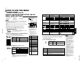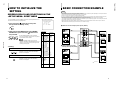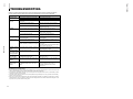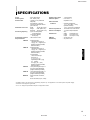
1
TM-H1750CG
OPERATING INSTRUCTIONS
[ TM-H1750CG/E / TM-H1750CG/U ]
COLOR VIDEO MONITOR
INSTRUCTIONS
FRANÇAIS
TM-H1750CG
DEUTSCH
ENGLISH
BEDIENUNGSANLEITUNG : FARB-VIDEO-MONITOR
MANUEL D’INSTRUCTIONS : MONITEUR VIDEO COULEUR
MANUALE DI ISTRUZIONI : MONITOR VIDEO A COLORI
INSTRUCCIONES : MONITOR DE VIDEO A COLOR
!"#$%&'(&)
ITALIANO
For Customer Use:
Enter below the Serial No. which is located on the rear of the cabinet.
Retain this information for future reference.
Pour l’usage du client:
Enter ci-dessous le numéro de série qui est situé sur l’arrière du coffret.
Conserver cette information pour une référence ultérieure.
Model No. :
Numéro de modèle :
TM-H1750CG
ESPAÑOL
Serial No. :
Numéro de série :
PHASE
BRIGHT
VOLUME/SELECT
MENU
UNDER
SCAN
COLOR
OFF
BLUE
CHECK
ASPECT
A
B
C SLOT D
POWER
INPUT SELECT
CHROMA CONTRAST
TM-H1750CG
LCT1025-001A-H
1101-Y-U-JMT
Jan. 2002 No. 51923
WARNINGS
To prevent fire or shock hazard, do not expose this
monitor to rain or moisture. Dangerous high voltages
are present inside the unit. Do not remove the back
cover of the cabinet. When servicing the monitor,
consult qualified service personnel. Never try to service
it yourself.
WARNING : THIS APPARATUS MUST
BE EARTHED.
Machine Noise Information Ordinance 3. GSGV,
January 18, 1991: The sound pressure level at the
operator position is equal or less than 70 dB(A)
according to ISO 7779.
Improper operations, in particular alternation of high
voltage or changing the type of tube may result in x-ray
emission of considerable dose. A unit altered in such a
way no longer meets the standards of certification, and
must therefore no longer be operated.
No.51923
This monitor is equipped with a 3-blade grounding-type
plug to satisfy FCC rule. If you are unable to insert the
plug into the outlet, contact your electrician.
FCC INFORMATION (U.S.A. only)
The power supply voltage rating of this product is AC 120 V (For U.S.A. and Canada only) and AC 230 V (For European countries
or United Kingdom), the power cord attached conforms to the following power supply voltage and countries. Use only the power
cord designated to ensure Safety and EMC regulations of each countries.
Power cord
CAUTION: Changes or modification not approved by
JVC could void the user's authority to operate the
equipment.
NOTE: This equipment has been tested and found to
comply with the limits for a Class B digital device,
pursuant to Part 15 of the FCC Rules. These limits are
designed to provide reasonable protection against
harmful interference in a residential installation. This
equipment generates, uses and can radiate radio
frequency energy and, if not installed and used in
accordance with the instructions, may cause harmful
interference to radio communications. However, there is
no guarantee that interference will not occur in a
particular installation. If this equipment does cause
harmful interference to radio or television reception,
which can be determined by turning the equipment off
and on, the user is encouraged to try to correct the
interference by one or more of the following measures:
– Reorient or relocate the receiving antenna.
– Increase the separation between the equipment and
receiver.
– Connect the equipment into an outlet on a circuit
different from that to which the receiver is connected.
– Consult the dealer or an experienced radio/TV
technician for help.
Notice (U.S.A. only)
This product utilizes both a Cathode Ray Tube (CRT) and
other components that contain lead. Disposal of these
materials may be regulated in your community due to
environmental considerations. For disposal or recycling
information please contact your local authorities, or the
Electronics Industries Alliance: <http://www.eiae.org.>
Power supply voltage : AC 120 V
Countries
: U.S.A. and Canada
AC 230 V
European countries
AC 230 V
United Kingdom
Warning:
● Do not use the same Power Cord for AC 120 V as for AC 230 V. Doing so may cause malfunction, electric shock
or fire.
Note for the United Kingdom power cord only
The plug on the United Kingdom power cord has a built-in fuse. When replacing the fuse, be sure to use only a correctly rated
approved type, re-fit the fuse cover.
(Consult your dealer or qualified service personnel.)
How to replace the fuse
Open the fuse compartment with the blade screw driver, and
replace the fuse.
(* An example is shown in the illustration.)
Fuse
SCREEN BURN
● It is not recommended to keep a certain still image displayed on screen for a long time as well as displaying extremely bright
images on screen. This may cause a burning (sticking) phenomenon on the screen of cathode-ray tube. This problem does
not occur as far as displaying normal video playback motion images.
CONTENTS
SAFETY PRECAUTIONS ................................................................................. 2
CONTROLS AND FEATURES ......................................................................... 4
PRECAUTIONS
● Use only the power source specified on the unit.
(120 V AC/230 V AC, 50 Hz/60Hz)
● When not using this unit for a long period of time, or when
cleaning it, be sure to disconnect the power plug from the
AC outlet.
● Do not allow anything to rest on the power cord. And do not
place this unit where people will tread on the cord. Do not
overload wall outlets or power cords as this can result in a
fire or electric shock.
● Avoid using this unit under the following conditions:
– in extremely hot, cold or humid places,
– in dusty places,
– near appliances generating strong magnetic fields,
– in places subject to direct sunlight,
– in badly ventilated places,
– in automobiles with doors closed.
● Do not cover the ventilation slots while in operation as this
could obstruct the required ventilation flow.
● When dust accumulates on the screen surface, clean it with
a soft cloth.
POWER CONNECTION
ENGLISH
In order to prevent any fatal accidents caused by misoperation
or mishandling the monitor, be fully aware of all the following
precautions.
TM-H1750CG
1-2
SAFETY PRECAUTIONS
● Unplug this unit from the AC outlet and refer servicing to
qualified service personnel under the following conditions:
– when the power cord is frayed or the plug is damaged,
– if liquid has been spilled into the unit,
– if the unit has been dropped or the cabinet has been
damaged,
– when the unit exhibits a distinct change in performance.
● Do not attempt to service this unit yourself as opening or
removing covers may expose you to dangerous voltage or
other hazards. Always refer servicing to qualified service
personnel.
● When replacement parts are required, have the service
personnel verify in writing that the replacement parts he/
she uses have the same safety characteristics as the
original parts. Use of manufacture’s specified replacement
parts can prevent fire, shock, or other hazards.
● Upon completion of any servicing or repair work to this unit,
please ask the service personnel to perform the safety
check described in the manufacturer’s service literature.
● When this unit reaches the end of its useful life, improper
disposal could result in a picture tube implosion. Ask
qualified service personnel to dispose of this unit.
CONTROLS AND FEATURES (INPUT CARD: OPTIONAL) ........................................ 7
PREPARATION................................................................................................. 8
HOW TO HANDLE BASIC OPERATIONS ....................................................... 9
HOW TO USE THE MENU FUNCTIONS.........................................................11
HOW TO INITIALIZE THE SETTING .............................................................. 14
BASIC CONNECTION EXAMPLE.................................................................. 15
HOW TO USE EXTERNAL CONTROL .......................................................... 17
TROUBLESHOOTING .................................................................................... 18
SPECIFICATIONS .......................................................................................... 19
APPENDIX ...................................................................................................... 20
2
3
CONTROLS AND FEATURES
FRONT VIEW
REAR VIEW
<Front Panel>
<Rear Panel>
VIDEO A
1
16
CHROMA CONTRAST
VOLUME/SELECT
MENU
UNDER
SCAN
COLOR
OFF
BLUE
CHECK
ASPECT
A
B
C SLOT D
REMOTE
POWER
IN
15
PHASE
BRIGHT
SLOT
18
OUT
VIDEO B
INPUT SELECT
17
19
IN
OUT
VIDEO A
IN
OUT
VIDEO B
CHROMA CONTRAST
TM-H1750CG
PHASE
VOLUME/SELECT
MENU
UNDER
SCAN
COLOR
OFF
BLUE
CHECK
ASPECT
BRIGHT
A
B
C SLOT D
POWER
2
3
4
5
6
7
8
9 10 11
12
13 14
IN
IN
INPUT SELECT
20
IN
Y/C
OUT
Y/C
OUT
AUDIO A
IN
OUT
AUDIO B
IN
Lights when the tally control signal is ON. The tally control
signal is input through the REMOTE (external control)
remote terminal. For details, refer to Page 17.
2 Chroma/Phase button
PHASE]
[ CHROMA/
No.51923
Press this button to activate the picture color density
adjustment mode or picture hue adjustment mode. Each
time you press the button, the adjustment item changes.
Picture color density f Picture hue
Adjust the value with the VOLUME/SELECT buttons 4.
Also used as a control button in the menu function mode.
3 Contrast/Brightness button
[CONTRAST / BRIGHT
]
Press this button to activate the picture contrast adjustment
mode or picture brightness adjustment mode. Each time
you press the button, the adjustment item changes.
Picture contrast f Picture brightness
Adjust the value with the VOLUME/SELECT buttons 4.
Also used as a control button in the menu function mode.
4 Volume/Select buttons
+]
[VOLUME/SELECT –
Adjusts the speaker volume. Also used as a control
button in the menu function mode.
5 Menu button [MENU]
Displays and disappears the <MENU> screen.
Pressing the CHROMA/PHASE button 2 with the Menu
button depressed will display the <SET-UP MENU>
screen.
6 Under Scan button [UNDER SCAN]
Reduces the screen size to display the entire image.
Press the button again to cancel Under Scan.
When selected, the Under Scan button lights.
7 Color Off button [COLOR OFF]
Cuts color signals to display a black and white image.
Press the button again to restore the original color.
When selected, the COLOR OFF button lights.
Note:
● This function is invalid with RGB input.
8 Blue Check button [BLUE CHECK]
Cuts red and green signal components. Only blue signal
components are shown. Press the button again to
restore the normal image.
When selected, this button lights.
AUDIO A
21
IN
OUT
AUDIO B
22
9 Aspect button [ASPECT]
IN
OUT
Press this button to change the aspect ratio from 4:3 to
16:9.
10 Input A (VIDEO) button [INPUT SELECT A]
Selects the video and audio signals input to the VIDEO A
* and AUDIO A q terminals on the rear panel. The
button lights when selected.
11 Input B (VIDEO Y/C) button [INPUT SELECT B]
Selects the video and audio signals input to the VIDEO B
( or VIDEO B (Y/C) ) and AUDIO B w terminals on
the rear panel. The button lights when selected.
Note:
● The VIDEO B terminals include a video terminal (BNC
connector) and a Y/C terminal (mini-DIN 4-pin connector).
The Y/C (S-video) terminal has priority.
12 Input C/D (Slot) buttons [INPUT SELECT C/D
(SLOT)]
Selects the signals to be input via the input cards installed
in the rear panel card slots.
C, D: Selects the image from the input card in the slot.
For details on input connectors and using the INPUT
SELECT button, refer to page 7.
Unlit
: The main power is OFF.
Orange : The main power is ON, but the monitor’s power
is OFF (in the stand-by mode).
Green : The main power is ON, and the monitor’s power
is ON (in the normal operation mode).
14 Power switch [POWER
16 Input card slot (SLOT)
Optional input cards can be installed in this slot. Input
cards are not provided when you purchase this monitor.
17 REMOTE (external control) terminal
Connect this terminal to an external control unit to enable
remote operation of the monitor.
Refer to the HOW TO USE EXTERNAL CONTROL on
page 17 for more details.
18 Video A terminals [VIDEO A IN/OUT]
Video signal input (IN) and output (OUT) terminals.
The output terminal is bridge-connected.
IN
: Video signal input terminal
OUT : Bridge-connected video signal output terminal
Notes:
* For corresponding audio signals, use the AUDIO A
terminals q.
* Also refer to BASIC CONNECTION EXAMPLE
on page 15.
19 Video B terminals [VIDEO B IN/OUT]
13 Power indicator
]
Press the power switch to turn the monitor’s power ON or
OFF when the main power is ON.
Note:
● When RUSH DELAY is set to SLOW, it takes about
three seconds before power is actually supplied after
the power switch is pressed.
A built-in speaker is located inside the right side panel
when the monitor is viewed from the front.
Video signal input (IN) and output (OUT) terminals.
The output terminal is bridge-connected.
IN
: Video signal input terminal
OUT : Bridge-connected video signal output terminal
Notes:
* For corresponding audio signals, use the AUDIO B
terminals w.
* Also refer to BASIC CONNECTION EXAMPLE on
page 15.
20 Video B (Y/C) terminals [VIDEO B Y/C IN/OUT]
Y/C (S-video) signal input (IN) and output (OUT) terminals. The output terminal is bridge-connected.
IN
: Y/C-separated (S-video) video signal input
terminal
OUT : Bridge-connected Y/C-separated (S-video) signal
output terminal.
Notes:
* For corresponding audio signals, use the AUDIO B
terminals w.
* When both VIDEO B terminals are connected (input) at
the same time, the Y/C terminal has priority.
* Also refer to BASIC CONNECTION EXAMPLE
on page 16.
21 Audio A terminals [AUDIO A IN/OUT]
Input (IN) and output (OUT) terminals for the audio signal
corresponding to the VIDEO A terminals *.
The output terminal is bridge-connected.
IN
: Audio signal input terminal
OUT : Bridge-connected audio signal output terminal
Notes:
* For corresponding video signals, use the VIDEO A
terminal *.
* Also refer to BASIC CONNECTION EXAMPLE
on pages 15 and 16.
22 Audio B terminals [AUDIO B IN/OUT]
Input (IN) and output (OUT) terminals for the audio
signals corresponding to the VIDEO B terminals ( or
VIDEO B (Y/C) terminals ).
The output terminal is bridge-connected.
IN
: Audio signal input terminal
OUT : Bridge-connected audio signal output terminal
Notes:
* For corresponding video signals, use the VIDEO B
terminals ( or VIDEO B (Y/C) terminals ).
* Also refer to BASIC CONNECTION EXAMPLE
on pages 15 and 16.
5
1-3
TM-H1750CG
15 Speaker
4
OUT
OUT
ENGLISH
1 Tally lamp
(cont’d)
TM-H1750CG
1-4
CONTROLS AND FEATURES
CONTROLS AND FEATURES
(INPUT CARD: OPTIONAL)
REAR VIEW
COMPONENT/RGB INPUT CARD (OPTIONAL:
IF-C01COMG)
<Rear Panel>
25
Input (IN) and output (OUT) terminals for component
(color deference) or RGB signals.
The IN and OUT terminals are bridge-connected.
(When no cable is connected to the OUT terminal, the
input signal is automatically terminated.)
Select component signal : press INPUT SELECT C button
Select RGB signal
: press INPUT SELECT D button
G/Y
REMOTE
For U.S.A. and Canada
IN
OUT
B/P B /B-Y
1
VIDEO A
IN
To AC outlet
(230 V AC,
50 Hz/60 Hz)
IN
OUT
IN
25
IN
Y/C
IN
OUT
IN
2 Synchronized signal input/output terminals
OUT
4
OUT
HD/C S
AUDIO A
For Europe
OUT
R/P R /B-Y
VIDEO B
OUT
AUDIO B
IN
OUT
IN
OUT
VD
25
IN
2
OUT
AUDIO
24
For the United Kingdom
3
23
OUT
IN
3 Audio input/output terminals
Compatible signal formats:
480/50i, 480/60i
23 Main power switch
No.51923
Press the switch to turn the main power ON or OFF. When
the main power is ON, the power lamp on the front panel
lights in orange and the monitor enters the stand-by
mode.
I : ON : OFF
24 AC inlet [AC IN]
Power input connector. Connect the provided AC power
cord t to an AC outlet (120 V AC or 230 V AC,
50 Hz/60 Hz).
Input (IN) and output (OUT) terminals for audio signals.
The IN and OUT terminals are bridge-connected.
25 Power cord
4 Connection terminal (to a Color Video Monitor)
Connects the provided power cord (120 V AC or
230 V AC, 50 Hz/60 Hz) to the AC IN connector r.
Caution:
In North America (USA and Canada), this monitor comes
with one power cable. In Europe and the United Kingdom, two power cables are provided (one for use in
continental European countries and the other for the UK).
Be sure to use the power cable that is appropriate for the
AC outlets used in your region. If none of the power
cables provided is suitable, please contact your dealer or
qualified service personnel to obtain the correct type of
power cable.
Attach to the connection terminal of your color video
monitor.
SDI INPUT CARD (OPTIONAL: IF-C01SDG)
1 Output terminal for a selected component
serial digital signal
SWITCHED
OUT
1
IN
SDI 1
IN
SDI 2
2
4
AUDIO 1
IN
OUT
3
AUDIO 2
Compatible signal formats: 480/60i, 480/50i
Note:
● The optional input cards shown below cannot be used.
Using any of these cards will void your warranty and may
result in damage or malfunction.
*Video input card (IF-C01PNG)
*HD-SDI input card (IF-C01HSDG)
6
Input (IN) and output (OUT) terminals for the vertical,
horizontal or complex synchronized signals.
The synchronized signals from these terminals have
priority over other terminals. When no synchronized signal
is input to these terminals, the synchronized signal from
the video input/output terminals (G/Y terminals) is valid.
The IN and OUT terminals are bridge-connected.
(When no cable is connected to the OUT terminal, the
input signal is automatically terminated.)
External sync is available with RGB input only. G on
SYNC cannot be used with RGB input.
ENGLISH
To AC outlet
(120 V AC,
50 Hz/60 Hz)
SLOT
1 Video input/output terminals
Output terminal for a selected digital signal (the input
displayed on the screen). The output signal is cablecompensated.
NOTE: When the monitor’s main power is OFF, no digital
signal is output.
In the standby mode, signals from the SDI 1 connector
are output.
2 Input terminals for component serial digital
signals
Input terminals for the digital signal.
Select SDI 1 : press INPUT SELECT C button
Select SDI 2 : press INPUT SELECT D button
3 Audio input/output terminals
Input (IN) and output (OUT) terminals for the analog
signals corresponding to SDI 1 and SDI 2.
NOTE: This input card cannot decode audio data even if
contained in the input digital signal.
4 Connection terminal (to a Color Video
Monitor)
Attach to the connection terminal of your color video
monitor.
7
PREPARATION
HOW TO HANDLE BASIC
OPERATIONS
INSTALLING THE INPUT CARD
BASIC OPERATION
1. Turn off the Color Video Monitor’s main power and unplug the power cable
from the AC outlet.
2. Unscrew the screws and remove the slot cover from the slot (on the rear side
of the monitor) in which you are going to install the card.
1. Press the main power switch to turn on the power.
2. Press the POWER switch to turn on the power.
Rear side of the TM-H1750CG
color video monitor
SLOT
3. Press the INPUT SELECT buttons to choose input.
REMOTE
Select video/audio signals input to terminals on the rear
panel. The selected button lights in green.
A
B
C SLOT D
Slot cover
INPUT SELECT
VIDEO A
IN
OUT
VIDEO B
IN
OUT
Y/C
IN
No.51923
3. Insert the Input Card’s board (green-colored) into the slot, fitting the board into
the guide rails on the top and bottom of the slot.
PAL
ON : Power turns ON. (Power indicator: lit)
Green : The main power is ON, and the monitor’s
power is ON (in the normal operation mode).
OFF : Power turns OFF. (Power indicator: unlit)
Orange : The main power is ON, but the monitor’s
power is OFF (in the standby mode)
Unlit
: The main power is OFF.
INPUT
SELECT
buttons
1 Input A
(VIDEO)
2 Input B
(VIDEO/Y/C)
VIDEO A terminal
3 Input C
4 Input D
Refer to page 7 for details about the input terminals
on each card and the INPUT SELECT button.
Terminals on the rear panel
Video signal input
VIDEO B terminal
Audio signal input
AUDIO A terminal
AUDIO B terminal
VIDEO B (Y/C) terminal
About the STATUS indication
● With the COLOR SYSTEM setting set
to AUTO mode, when you turn on the
power or select inputs, the color
system indication appears for about
3 seconds on the screen while PAL or
NTSC signals are being detected.
It does not appear when receiving a
B/W signal or when no signal is input.
Refer to page 11 for more information
about COLOR SYSTEM setting and
page 12 for more information about
STATUS indication setting.
Note: The Y/C (S-video) terminal has priority.
00 ~ 50
4. Press the VOLUME/SELECT buttons to adjust the
speaker volume.
Fit the board to
the guide rails.
SLOT
Knob
VOLUME/SELECT
REMOTE
Press this button to display the speaker volume level on the
screen.
+ : The Built-in speaker volume is increased. (00 = 50)
– : The Built-in speaker volume is decreased. (50 = 00)
VOLUME
:
20
* Screen indication will disappear about 10 seconds after operating.
* The on-screen display goes off when you press MENU button.
VIDEO A
IN
Guide rails
OUT
VIDEO B
IN
IN
Knob
ENGLISH
POWER
STATUS indication
(PAL or NTSC)
–
PICTURE ADJUSTMENT
UPPER
OUT
Y/C
Input card (the illustration
shown is of the IF-C01COMG)
1. Press select buttons corresponding to the item
you want to adjust.
CHROMA CONTRAST
SLOT
4. Push the Input Card in so that its front panel touches the monitor’s rear panel.
5. Secure the Input Card by replacing the screws removed in Procedure 2.
PHASE
BRIGHT
+
The item you select is displayed on the screen.
1 Chorma control : Press the CHROMA/PHASE button once.
2 Phase control
: Press the CHROMA/PHASE button twice.
3 Contrast control : Press the CONTRAST/BRIGHT button once.
4 Brightness control : Press the CONTRAST/BRIGHT button twice.
* Pressing the CHROMA/PHASE button and CONTRAST/BRIGHT button
alternately while the item is shown on screen restores the previous status.
When no item is shown on screen, CHROMA and CONTRAST have priority.
2. Adjust with the VOLUME/SELECT buttons.
–40 ~ +40
PHASE
:
00
PHASE
:
00
–
Notes:
+
LOWER
REMOTE
VOLUME/SELECT
CHROMA
(Chroma)
VIDEO A
IN
OUT
VIDEO B
IN
IN
Items
OUT
Y/C
lighter
deeper
reddish
greenish
lower
higher
darker
brighter
* Screen indication will disappear about 10 seconds after operating.
* The on-screen display goes off when you press MENU button.
8
● Phase control is effective only in the
NTSC color system mode.
● Chroma control is not effective when
receiving RGB and B/W or when no
signal is input. (Except when a
component signal is input.)
● When CHROMA is adjusted to “–40,”
the picture becomes less colorful.
● “NO EFFECT” is displayed (for about
3 seconds) when your selected
function has no effect.
● To change the display position on
screen, set UPPER or LOWER with
ADJ. BAR POSI.
9
1-5
TM-H1750CG
NOTE : Do not touch the terminal connected to the monitor or board pattern.
Do not remove slot covers from the monitor’s slots if they are not in use.
PHASE
(Phase)
CONTRAST
(Contrast)
BRIGHT
(Brightness)
VOLUME/SELECT button
–
+
TM-H1750CG
1-6
HOW TO HANDLE BASIC
OPERATIONS (cont’d)
HOW TO USE THE MENU FUNCTIONS
DISPLAY AND SELECTION IN THE <MENU>
SCREEN MODE (SETTING)
<MENU> screen
You can set the following menu items.
Set them depending on your needs.
Use these buttons for video signal control.
UNDER SCAN
• APERTURE
• ADJ. BAR POSI.
• COLOR TEMP.
Press the UNDER SCAN button to reduce the size of display area so that the whole
picture is displayed on screen. Use to check the picture frame.
1
• COLOR SYSTEM
• COMPO. LEVEL*
• RUSH DELAY
1. Press the MENU button.
COLOR OFF
MENU
To display a black and white picture, press the COLOR OFF button to input the luminance signal only. Use to check noise in the luminance signal or for white balance
adjustment.
CHROMA CONTRAST
PHASE
BLUE CHECK
BRIGHT
APERTURE
Input the standard color-bar signal for your TV system and display it on the screen.
When the BLUE CHECK button is pressed, the red and green signals are cut and only
the blue signal is displayed. The BLUE CHECK function adjusts and checks CHROMA
(COLOR) GAIN and PHASE.
Make sure that COMPO. LEVEL has been initialized when a component signal is input.
ADJ. BAR POSI.
COLOR TEMP.
COLOR SYSTEM
00
LOWER
6500
AUTO
00
STD
3
Function
displayed
CHROMA/
PHASE
CONTRAST/
BRIGHT
4
EXIT
CHROMA CONTRAST
PHASE
A selection mark (4) is put next to the selected item.
Front panel
button
:
:
:
:
:
:
2
The <MENU> screen is displayed.
* The on-screen display goes off automatically after about five
minutes with operation performed.
2. Press the CHROMA/PHASE or CONTRAST/BRIGHT
button to select MENU items.
Note:
● No effect with RGB input.
< MENU >
‰ APERTURE
ADJ. BAR POSI.
COLOR TEMP.
COLOR SYSTEM
COMP. LEVEL
RUSH DELAY
VOLUME/SELECT
MENU
BRIGHT
<Front panel buttons>
1 Selection mark (4): Indicates the
Contents
menu item you select.
2 Menu item: Menu items you can
Forward selection mark (4)
select.
3 Setting display: Indicates the current
settings (value).
4 Function display: The functions of
the front panel buttons (5 buttons on
the left) correspond to the function
displayed.
Reverse selection mark (4)
COMPO. LEVEL*
RUSH DELAY
ENGLISH
VIDEO SIGNAL CONTROLS
3. Press the VOLUME/SELECT buttons to set.
Blue
VOLUME/SELECT
Blue
Blue
1. Input the standard color-bar signal for your TV system and display it on the screen.
2. Press the BLUE CHECK button.
3. Press the CHROMA button to adjust the chroma so that the blue bars on the left and
right sides of the screen have the same brightness.
4. (Only when an NTSC signal is input) Press the PHASE button to adjust the phase so
that the two blue bars at the center of the screen have the same brightness.
5. (Only when an NTSC signal is input) Repeat procedures 3 and 4 for the adjustment so
that all four blue bars on the screen have the same brightness.
Blue
No.51923
[Procedure]
VOLUME/
SELECT (+)
Function
displayed
+
Menu items
Initializing COMPO. LEVEL (when a component signal is input)
with the IF-C01COMG component/RGB input card inserted
When a component signal is input, be sure to adjust (initialize) the COLOR offset in
COMPO. LEVEL.
Blue
Blue
Blue
Blue
[Procedure]
Function
displayed
Increase (to max. value)
–
Forward the setting value
Decrease (to min. value)
1
Reverse the setting value
Purpose
Setting range
APERTURE
Picture aperture level
00
ADJ.BAR POSI
Volume bar position
LOWER
COLOR TEMP.
Color temperature of white
balance
6500
+01
COLOR SYSTEM
Color system
AUTO
COMPO. LEVEL*
Component level
–40
RUSH DELAY
Delay time
STD.
••••••••••••
+39
+40
UPPER
Contents
Forward the menu item.
Contents
4
VOLUME/
SELECT (–)
When you have finished making the adjustment, press the BLUE CHECK button to
deactivate.
1. Input the standard color-bar signal for your TV system and display it on the screen.
2. Press the BLUE CHECK button.
3. Select COMPO. LEVEL in the <MENU> screen and then adjust it with VOLUME +/–
buttons so that the blue bars on the left and right sides of the screen have the same
brightness.
4. Quit the <MENU> screen and press the BLUE CHECK button.
5. Make sure that the blue bars on the left and right sides of the screen have the same
brightness.
6. Repeat procedures 3, 4 and 5 for the adjustment so that the blue bars on the left and
right sides of the screen have the same brightness.
Front panel
button
Reverse the menu item.
–
Lower the adjustment
value. (to the minimum)
+
Raise the adjustment
value. (to the maximum)
4
Forward the setting value.
1
Reverse the setting value.
EXIT
Exits the <MENU> screen.
UPPER
<ADJ. BAR POSI> screen
9300
NTSC
AUTO
PAL
–39 • • –01
00
+1 • • +9
BRIGHT
:
BRIGHT
:
00
+10
SLOW
* For normal use, leave the COLOR SYSTEM setting to AUTO.
If reception is unsatisfactory in AUTO position, set it to the appropriate color system mode (NTSC or PAL).
* COMPO. LEVEL is displayed only with COMPONENT (SDI) input. (Shown with INPUT-C and INPUT-D
except for RGB input.)
00
EXIT
4. If you want to set the other menu items, repeat
procedures 2 and 3.
LOWER
CHROMA CONTRAST
5. Press the MENU button to quit.
PHASE
VOLUME/SELECT
MENU
BRIGHT
<Front panel buttons>
MENU
Front panel
button
MENU
10
Function
displayed
EXIT
Contents
Quit (or Release) the <MENU>
screen
The upper screen; when setting
“UPPER” in “ADJ. BAR POSI.”
The lower screen; when setting
“LOWER” in “ADJ. BAR POSI.”
11
HOW TO USE THE MENU
FUNCTIONS (cont’d)
• WHITE BALANCE
• CONTROL LOCK
• STATUS DISPLAY
• REMOTE SYSTEM
• INPUT REMOTE
1
Notes:
● Parameters for H. POSITION and V. POSITION can be set separately depending on
the signal (Input A (VIDEO), Input B (VIDEO), Input C or Input D) selected with the
2
input select buttons on the front panel.
Select the required video input with the input select buttons on the front panel in
advance.
● WHITE BALANCE can be set independently at 6500 or 9300 for the color temperature
value.
Set COLOR TEMP. to 6500 or 9300 on the <MENU> screen beforehand.
● INPUT REMOTE is shown when REMOTE SYSTEM is set to MAKE.
<SET-UP MENU>
‰ PICTURE SUB ADJ.
H. POSITION
V. POSITION
WHITE BALANCE
CONTROL LOCK
STATUS DISPLAY
REMOTE SYSTEM
INPUT REMOTE
No.51923
1. While pressing the MENU button, press the
CHROMA/PHASE button.
MENU
PHASE
The <SET-UP MENU> screen is displayed.
* The on-screen display goes off automatically after about five
minutes with operation performed.
2. Press the CHROMA/PHASE or CONTRAST/BRIGHT
button to select the desired menu item.
CHROMA CONTRAST
PHASE
BRIGHT
PICTURE SUB ADJ.
H. POSITION
V. POSITION
A selection mark (4) is put next to the selected item.
Front panel
button
Function
displayed
Contents
CHROMA/
PHASE
Forward selection mark (4)
CONTRAST/
BRIGHT
Reverse selection mark (4)
00
00
:
:
:
:
OFF
ON
MAKE
A–D
H. POSITION
3
4
CHROMA CONTRAST
VOLUME/SELECT
MENU
BRIGHT
<Front panel buttons>
1 Selection mark (4): Indicates the
menu item you select.
2 Menu item: Menu items you can
select.
3 Setting display: Indicates the
current settings (value).
4 Function display: The functions of
the front panel buttons (5 buttons
on the left) correspond to the
function displayed.
Contents
Forward the menu item.
Reverse the menu item.
–
Lower the adjustment
value. (to the minimum)
+
Raise the adjustment
value. (to the maximum)
4
Forward the setting value.
STATUS DISPLAY
1
Reverse the setting value.
REMOTE SYSTEM
3. Press the VOLUME/SELECT buttons to set.
EXIT
Exit the <MENU>
screen.
DRV
Selects DRIVE adjustment.
CUTO
VOLUME/SELECT
Front panel
button
VOLUME/
SELECT (+)
VOLUME/
SELECT (–)
Function
displayed
+
4
CUTO
–
1
DRV
Contents
Increase (to max. value)
Forward the setting value
Selects CUT OFF setting screen
Decrease (to min. value)
Reverse the setting value
Selects DRIVE setting screen
Notes:
R. DRIVE
B. DRIVE
CUT OFF R. CUT OFF
G. CUT OFF
B. CUT OFF
CONTROL LOCK
STATUS DISPLAY
REMOTE SYSTEM
INPUT REMOTE
Settings
Selects CONTRAST/BRIGHT/CHROMA/PHASE. The
selected setting screen is shown. Select the function display for
adjustment.
Adjusts contrast.
Adjusts brightness.
Adjusts color density.
*1
Adjusts hue.
*1
Adjusts the horizontal position of the
screen (+: Horizontal position shifts
to the right/-: Horizontal position shifts to
the left)
Adjusts the vertical position of the screen
(+: Vertical position moves up/-: Vertical
position moves down)
Adjusts the white balance.
–10
Adjusts red level.
Adjusts blue level.
Adjusts red cut off.
Adjusts green cut off.
Adjusts blue cut off.
Sets the operation buttons on the front
panel to control lock mode.
Sets the status display of the color system.
Sets the external control function method.
Sets external control of input selection.
(Shown only when REMOTE SYSTEM is
set to MAKE.)
–01
00
+10
00
+01 • •
+01 • •
+09
– 01
+09
+10
–01
–01
00
00
+01 • •
+01 • •
+09
+09
+10
+10
–10
–10
–9 • •
–9 • •
–9 • •
–9 • •
–5
•••
– 01
00
+1
•••
+5
–5
•••
–01
00
+1
•••
+5
– 10
Selects the drive (DRV) or cut off (CUTO) adjustment. The selected
setting screen is shown. Select the function display for adjustment.
–20 –19 • • –01 00 +01 • • +19 +20
– 20 – 1 9 • • – 01 00 +01 • • +19 +20
–20 –19 • • –01 00 +01 • • +19 +20
–20 –19 • • –01 00 +01 • • +19 +20
–20 –19 • • –01 00 +01 • • +19 +20
OFF
ON
OFF
MAKE
ON
TRG.
A–D
*2
A/B
*2
*1 May not be shown depending on the type of signals input.
*2 Refer to HOW TO USE EXTERNAL CONTROL on page 17 for more details.
RB
Selects CUT OFF
adjustment.
Adjusts red and blue
signal level.
4. To set the other set-up menu items, repeat the
procedures 2 and 3.
5. Press the MENU button to quit.
MENU
Front panel
button
MENU
Function
displayed
EXIT
Contents
Quit (or Release) the <MENU>
screen
Note:
Setting
Description
RGB
Adjusts red, green and
blue signal level.
MAKE
Make contact system: Controls the function with H and L (shortcircuits or opens 15th terminal (GND)).
Turns the ON-SCREEN
display on or off. (This
function is effective only
in the DRIVE or CUT OFF
adjustment mode.)
TRG.
DISP
Trigger system: Controls the function by short-circuiting (shortcircuits or opens 15th terminal (GND)) with pulse (about 1 sec.)
A-D
Switches the input by short-circuiting a specified signal line in
INPUT A, B, C, or D.
A/B
Switches between INPUT A and INPUT B with D-sub pin 2.
(Also, refer to HOW TO USE EXTERNAL CONTROL on page 17.)
● When the CONTROL LOCK function is
set to ON, pressing operation buttons
on the front panel will display the
message “CONTROL LOCK ON!” on
the screen for about 3 seconds.
● The CONTROL LOCK function is
maintained even when the power is
turned off.
● To turn off the CONTROL LOCK
function, while holding the MENU button
press the CHROMA/PHASE button.
Then set the CONTROL LOCK function
to OFF.
● Even when the CONTROL LOCK
function is set to ON, the following
operations are available:
– Power Switch operation
– Volume control with the VOLUME/
SELECT buttons
– Display or disappear of the <SET-UP
MENU> screen.
● The STATUS DISPLAY function can be
set to display (ON) or not display (OFF)
the present color system when the
power is turned on or the input signal is
changed. Refer to page 9 for more
information.
● When REMOTE SYSTEM is set to
MAKE and any one of the INPUT A to D
buttons, the UNDER SCAN button,
COLOR OFF button or the ASPECT
button is pressed, “REMOTE ON!”
appears on screen for about 3 seconds.
(Not shown with CONTROL LOCK set
to ON.)
● When REMOTE SYSTEM is set to
TRG, the front panel controls can be
operated.
● INPUT REMOTE and REMOTE
SYSTEM are enabled when REMOTE
ENABLE is set to ON.
13
1-7
TM-H1750CG
● For WHITE BALANCE items, select the CUT OFF or DRIVE
setting screen, then select the function display for adjustment.
● Press the EXIT (MENU) button to return to the <SET-UP
MENU> screen.
DRIVE
Purpose
Image sub adjustment
Notes:
Function
displayed
CONTROL LOCK
INPUT REMOTE
V. POSITION
WHITE BALANCE
WHITE BALANCE
12
:
:
EXIT
PHASE
CHROMA
CONTRAST
BRIGHT
CHROMA
PHASE
<SET-UP MENU> screen
You can set the following set-up menu items.
• PICTURE SUB ADJ.
• H. POSITION
• V. POSITION
Set-up menu items
PICTURE SUB ADJ.
ENGLISH
DISPLAY AND SELECTIONS IN THE <SET-UP
MENU> MODE (SETTING)
TM-H1750CG
1-8
HOW TO INITIALIZE THE
SETTING
BASIC CONNECTION EXAMPLE
Notes:
SCREEN DISPLAY AND SELECTIONS IN THE
<SET-UP MENU> RESET MODE
• Before connecting your system, make sure that all units are turned off.
• The illustration below shows some examples of different connections. Terminal connections may differ depending on the component connected.
Be sure to refer to the instructions provided with the unit(s) you are connecting.
• Each pair of input (IN) and output (OUT) terminals are bridge-connected.
• If you’re not connecting any equipment to a bridged output (OUT) terminal, be sure not to connect any other cables to the bridged output (OUT)
terminal as this will cause the terminating resistance switch to open (auto terminate function).
• When making a bridge connection, connect the input (IN) and output (OUT) terminals on the monitor to separate video components.
You can set <MENU> and <SET-UP MENU> screen items, picture adjustment items and
the volume level to their factory-set (initial) values.
<SET-UP MENU> RESET screen
<SET–UP MENU> RESET
Are you
“Yes” then
“No”
then
1. Press the Power ( ) switch to turn the power
OFF (activate the standby mode).
(For example, if both terminals are connected to the same VCR, resonance may occur except during playback. This is caused by the same video
signal “looping” between the VCRs, and is not a malfunction.)
• Select the video input signal (INPUT A(VIDEO) or INPUT B (VIDEO/Y/C)) with the INPUT SELECT buttons on the front panel. When both
VIDEO B terminals are connected (input) at the same time, the Y/C terminal has priority.
sure ?
<+>
<MENU>
VIDEO A Connection Example (Select Input A (VIDEO))
POWER
VIDEO A
Video
Video
APERTURE
ADJ. BAR POSI
COLOR TEMP
COLOR SYSTEM
COMPO. LEVEL
RUSH DELAY
PICTURE SUB ADJ.
CONTRAST
BRIGHT
CHROMA
PHASE
H. POSITION
V. POSITION
WHITE BALANCE
R. CUT OFF
G. CUT OFF
B. CUT OFF
R. DRIVE
B. DRIVE
CONTROL LOCK
STATUS DISPLAY
REMOTE SYSTEM
INPUT REMOTE
00
00
00
00
00
OFF
ON
MAKE
A–D
CHROMA
PHASE
CONTRAST
BRIGHT
00
00
00
00
VOLUME
No.51923
● The <SET-UP MENU> RESET screen will not be
displayed if the MENU or CHROMA/PHASE buttons are
pressed for a very short time. Keep pressing them until
the display screen appears.
3. Setting
Initialization is required.
VOLUME/SELECT
Press the VOLUME/SELECT [+] button.
* Initialization is completed, and the <SET-UP MENU>
RESET screen disappears.
Initialization is not required.
MENU
14
Press the MENU button.
* Initialization is aborted, and the <SET-UP MENU>
RESET screen disappears.
00
LOWER
6500
AUTO
00
STD
IN
OUT
VIDEO B
Video
(Video signal cable)
IN
ENGLISH
Sorts
Note:
PHASE
<MENU> screen
POWER
Initialization
Functions (Items)
(setting)
<SET-UP MENU> screen
MENU
Video Camera
Picture adjustment
CHROMA
The <SET-UP MENU> RESET screen is displayed.
* The screen automatically disappears when no operation
is performed after about 5 minutes.
(Video signal cable)
(Video signal cable)
Initial settings
Volume
2. While pressing both MENU button and CHROMA/
PHASE button, press the Power ( ) switch to turn
the power ON.
OUT
Audio
Video Monitor
(Audio signal cable)
IN
Y/C
OUT
00
00
00
00
00
00
AUDIO A
Audio
VCR
IN
OUT
AUDIO B
VIDEO B (VIDEO) Connection
Example (Select Input B (VIDEO))
Video Camera
IN
(Audio signal cable)
Video Monitor
Audio
OUT
(Audio signal
cable)
Video
(Video signal cable)
Video Monitor
VCR
Audio
(Audio signal cable)
Video Monitor
: Signal Flow
VCR
20
15
HOW TO USE EXTERNAL
CONTROL
BASIC CONNECTION EXAMPLE
(cont’d)
ABOUT EXTERNAL CONTROL
VIDEO B (Y/C) Connection Example (Select Input B (Y/C))
This monitor is provided with an external control terminal. MAKE (make contact) or TRG. (trigger) system can be selected.
(MAKE (make contact system): The function is controlled with H and L (short-circuit/open with the 15th pin GND).
(TRG. (trigger system): The function is controlled by short-circuiting with pulses (for about 1 second) (short-circuit/open with the
15th pin GND).
VIDEO A
* The 14th pin (REMOTE ENABLE) is controlled with MAKE even though TRG. is selected.
Note:
● When this monitor is externally controlled, the following buttons are disabled.
MAKE: INPUT-A to D, UNDER SCAN, COLOR OFF, ASPECT on the front panel.
OUT
VIDEO B
Video Camera
IN
OUT
Y/C (S-video)
(Y/C (S-video) signal cable)
VCR
IN
Video Monitor
10
Connections
Connect (short-circuit) the 15th terminal (GND) to each of the 1st through 14th terminals in the
3-lines 15-pins D-sub connector. The functions of each terminal are listed below.
Y/C
Y/C (S-video)
(Y/C (S-video) signal cable)
OUT
The Names and Functions of Terminals
AUDIO A
IN
VCR
Audio
No.51923
(Audio signal cable)
OUT
AUDIO B
IN
9
5
4 8
3 7
2 6
1
15
14
13
12
11
Video Monitor
Audio
OUT
(Audio signal cable)
: Signal Flow
No.
1
2
3
4
5
6
7
8
9
10
11
12
13
14
Names
TALLY
INPUT A
INPUT B
INPUT C
INPUT D
not used
not used
COLOR OFF
not used
ASPECT
UNDER SCAN
not used
not used
REMOTE ENABLE
15
GND
Functions
Puts on the tally lamp.
Changes the input to INPUT A
Changes the input to INPUT B
Changes the input to INPUT C
Changes the input to INPUT D
–
–
Changes the picture black-and-white.
–
Changes the screen ratio to 16:9
Makes the screen under-scan
–
–
Makes the external control from the
REMOTE terminal valid or invalid
Used as a ground terminal
Operations (OFF p[ ON)
Put off
Put on
Not change
Change
Not change
Change
Not change
Change
Not change
Change
–
–
–
–
Not change
Change
–
–
4:3
16:9
Over-scan
Under-scan
–
–
–
–
Invalid
Valid
–
*1
*2
*3
*4
*5
*6
*6
*8
*8
*8
*8
ENGLISH
IN
*6
*6
*6
*7
–
*1 : OFF stands for disconnection, and ON stands for short-circuit.
*2 : When INPUT REMOTE in the set-up menu is set to A/B, H: INPUT A and L: INPUT B are set.
*3 : When INPUT REMOTE in the set-up menu is set to A/B, pins not used should not be connected.
*4 : When INPUT REMOTE in the set-up menu is set to A/B, pins not used should not be connected.
*5 : When INPUT REMOTE in the set-up menu is set to A/B, pins not used should not be connected.
*6 : Do not connect.
*7 : Setting REMOTE ENABLE to ON enables remote control from the REMOTE terminal.
*8 : INPUT REMOTE setting in the set-up menu (REMOTE SYSTEM shown only when MAKE is selected.)
For the D-sub pins 2, 3, 4 and 5, 4-pin or 1-pin control can be set with INPUT REMOTE in the set-up menu.
• 4-pin control: Switches input by short-circuiting a specified signal line in INPUT A to D.
• 1-pin control: Switches between INPUT-A and INPUT-B only with the 2nd pin of the D-sub connector. In this case, INPUT-C and INPUT-D
cannot be selected.
Open (H): INPUT-A
Short-circuit (L): INPUT-B
NOTE : When more than two terminals are selected (short-circuited) from INPUT A through INPUT D, signal input is prioritized
alphabetically (A, B, C, D).
To control INPUT A through INPUT D, we recommend using the interlock switch, which turns off a switch when another
switch is turned on.
17
1-9
TM-H1750CG
16
Solutions to common problems related to your monitor are described here. If none of the solutions presented here
solves the problem, unplug the monitor and consult a JVC-authorized dealer or service center for assistance.
Problems
Points to be checked
Measures (Remedy)
Is the power plug loosened or disconnected?
Firmly insert the power plug.
Is the main power turned OFF?
Turn the main power ON. (See page 6.)
Is the video signal output from the connected
component?
Set the connected component correctly.
Is the input signal selected properly?
Select the required video signal input with the
Input select button. (See page 9.)
Is the video cable disconnected?
Connect the video signal cable firmly.
(See pages 15 and 16.)
Is the audio signal output from the connected
component?
Set the connected component correctly.
Is the volume output set to minimum?
Adjust the speaker volume with the VOLUME/
SELECT button. (See page 9.)
Is the audio cable disconnected?
Connect the audio signal cable firmly.
(See pags 15 and 16.)
Shaking picture.
Is the monitor close to a device generating a
strong magnetic field?
Move the device away from the monitor until the
picture stabilizes.
No colors, wrong
color, or dark picture.
Is the color system selected properly?
Set COLOR SYSTEM in the <MENU> screen to
AUTO. (See page 11.)
Has the picture control setting (CONTRAST,
BRIGHT, CHROMA or PHASE) been changed?
Set each picture control to the standard setting.
(See page 9.)
Press the COLOR OFF button and BLUE CHECK
button to adjust. (See page 10.)
Unnatural, irregularly
colored, or distorted
picture.
Is the monitor close to a speaker, magnet or any
other device generating a strong magnetic field?
Move the device away from the monitor and turn
the monitor’s power off. Wait at least 30 minutes,
then turn the power on again.
Dark stripes appear
at the top and bottom
of the screen, picture
vertically squeezed.
Is the aspect ratio set to 16:9?
Switch the aspect ratio to 4:3 with the ASPECT
button on the front panel.
The overall picture
size is too small.
Has the UNDER SCAN button been pressed so
the UNDER SCAN button lights?
Press the UNDER SCAN button to turn off the
button. (See page 4.)
Function buttons on
the front panel do not
function.
Has control of the buttons been locked? (Has
the CONTROL LOCK function been set to ON?)
Set CONTROL LOCK in the <SET-UP MENU>
screen to OFF. (See pages 12 and 13.)
The INPUT SELECT
buttons do not
function.
Is input selection under external control? (Has
the REMOTE ENABLE function been set to
valid?)
Set REMOTE SYSTEM in the <SET-UP MENU>
screen to TRG. (See pages 12 and 13.)
Set REMOTE ENABLE to OFF (invalid).
(See page 17.)
No power supply.
No picture with the
power on.
No sound.
No.51923
The following are not malfunctions:
● When a bright still image (such as a white cloth) is displayed for a long period, it may appear to be colored. This is due to the
structure of the cathode ray tube and will be deleted when another image is displayed.
● You experience a mild electric shock when you touch the picture tube. This phenomenon is due to a normal buildup of static
electricity on the CRT and is not harmful.
● The monitor emits a strange sound when the room temperature changes suddenly. This is only a problem if an abnormality
appears on the screen as well.
● If two or more monitors are operated next to each other, their images may shake or be distorted. This phenomenon is due to
mutual interference; it is not a malfunction. Move the monitors away from each other until the interference disappears or turn
the power off on any monitor that is not being used.
18
TM-H1750CG
1-10
TROUBLESHOOTING
TM-H1750CG
SPECIFICATIONS
Effective screen size
Scanning frequency
Horizontal resolution
Input terminals
VIDEO A
VIDEO B
AUDIO A
AUDIO B
REMOTE
: Color video monitor
: PAL, NTSC (3.58)
: 16-3/16" (41 cm) measured
diagonally,
90° deflection, in-line gun,
trio-dot type (phosphor dot-trio
pitch 0.27 mm)
: Width
12-7/8" (327.5 mm)
Height
9-5/8" (246.2 mm)
Diagonal
16-1/32" (407.1 mm)
: (H) 15.734 kHz (NTSC)
15.625 kHz (PAL)
(V) 59.94 Hz (NTSC)
50 Hz (PAL)
: 750 TV lines or more
Audio power output
Built-in speaker
Environmental
conditions
Power requirements
Power consumption
Dimensions
Weight
Accessory
: 1 W (monaural)
: 8 cm round x 1
impedance of 8 Ω
: Operation temperature:
0°C – 40°C (32°F – 104°F)
Operation humidity:
20 % – 80 % (non-condensing)
: 120 V/230 V AC, 50 Hz/ 60 Hz
: 1.2 A (120 V AC)/0.8 A (230 V
AC)
: Width
15-5/8" (395 mm)
Height
13-1/4" (334 mm)
Depth
16-1/2" (418.1 mm)
: 44.3 lbs (20.1 kg)
: AC power cord
: Composite video:
1 line, BNC connector x 2,
1 V(p-p), 75 Ω, negative sync
(bridge connection possible,
auto termination)
: Composite video:
1 line, BNC connector x 2,
1 V(p-p), 75 Ω, negative sync
(bridge connection possible,
auto termination)
Y/C-separated:
1 line, mini-DIN 4-pin
connector x 2
Y: 1.0 V (p-p), 75 Ω
C (BURST): 0.286 V (p-p),
75 Ω (NTSC)
0.3 V (p-p), 75 Ω (PAL)
(bridge connection possible,
auto termination)
: 1 line (monaural), RCA pin x 2
0.5 V(rms), high-impedance
(bridge connection possible)
: 1 line (monaural), RCA pin x 2
0.5 V(rms), high-impedance
(bridge connection possible)
: Point-of-contact connection,
1 line
D-sub connector (15-pin, 3-line)
ENGLISH
Type
Color system
Picture tube
* Illustrations used in this manual are for explanatory purposes only. The appearance of the actual product may differ slightly.
* Dimensions and weight are approximate.
* E. & O. E. Design and specifications subject to change without notice.
19
No.51923
1-11
TM-H1750CG
Dimensions
Unit : inch (mm)
< Side View >
< Front View >
16-1/2 (418.1)
16-1/8 (407)
15-5/8 (395)
1/16
(1.5)
VOLUME/SELECT
MENU
UNDER
SCAN
COLOR
OFF
BLUE
CHECK
ASPECT
A
BRIGHT
B
C SLOT D
POWER
INPUT SELECT
11-3/8 (288)
2-3/4 (68)
11-3/8 (286)
1/8 (3)
PHASE
1/8 (3)
CHROMA CONTRAST
TM-H1750CG
7 (175)
9-5/8 (246.2)*
13-1/4 (334)
12-7/8 (327.5)*
ø7/8 (20)
* Asterisks (*) are used to indicate front panel
dimensions.
Y/C (Mini DIN 4 pin) terminal
specification
2
4
Pin No.
IN
1
3
OUT 2
4
1
3
Y/C
Signal
1
GND (Y)
2
GND (C)
3
Y
4
C
APPENDIX: CONNECTION EXAMPLES FOR THE
SDI INPUT CARD
● To use the SWITCHED OUT terminal, the main power must be ON. (Unlike a bridged output, this connector outputs relocked
digital signals.)
● Signals output from the SWITCHED OUT terminal can be selected with INPUT-C (SDI-1) and INPUT-D (SDI-2) buttons on the
front panel (or remote control).
● When INPUT-A or INPUT-B is selected, this terminal outputs the signals last selected. In the standby mode, signals from the
SDI 1 connector are output.
20
1-12
No.51923
82 ,2!#