1
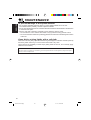
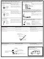
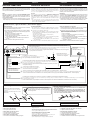
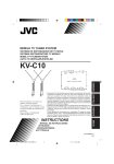
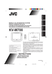
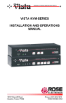
ENGLISH
DEUTSCH
MOBILE TV TUNER SYSTEM
FRANÇAIS
TRAGBARER TV-TUNER
SYSTEME DE TUNER DE TELEVISION MOBILE
MOBIEL TV-TUNERSYSTEEM
1
2
R AUDIO L
HEADPHONE
For installation and connections, refer to
the separate manual.
Für den Einbau und die Anschlüsse siehe
das eigenständige Handbuch.
Pour l’installation et les raccordements,
se référer au manuel séparé.
Bijzonderheden over de installatie en
aansluiting van het apparaat vindt u in
de desbetreffende handleiding.
2
TO DISPLAY
VOCAL
POWER
SUPPLY
OUTPUT
ANTENNA INPUT
1
VIDEO
NEDERLANDS
KV-C10
3
INPUT 1
INPUT 2
4
L AUDIO R
VIDEO
VIDEO
CONT
VIDEO
L AUDIO R
* This system is designed to enjoy TV programs by connecting JVC mobile
color monitor system KV-M700 (sold separately). All operations and functions
of the system including KV-M700 connected are explained in this
instructions.
* Dieses System wurde entwickelt, um mit dem tragbaren JVC-Farbmonitor
KV-M700 (separat erhältlich) Fernsehprogramme betrachten zu können.
Alle Funktionen und die Bedienung des Systems, einschl. Anschluss an
den KV-M700, sind in diesem Handbuch erklärt.
* Ce système est conçu pour vous permettre de regarder des émissions de
télévision en connectant le système de moniteur couleur mobile KV-M700
de JVC (vendu séparément). Le fonctionnement et les fonctions du système
avec le KV-M700 connecté sont expliqués dans ce manuel d’instructions.
* Het systeem is ontwor pen om op een aangesloten mobiel
kleurenmonitorsysteem van JVC (de KV-M700, apart leverbaar) naar TVprogramma’s te kijken en luisteren. Alle bediening en alle functies en
voorzieningen van het systeem, met inbegrip van de aangesloten KV-M700,
worden in deze handleiding besproken.
INSTRUCTIONS
BEDIENUNGSANLEITUNG
MANUEL D’INSTRUCTIONS
GEBRUIKSAANWIJZING
3351398B01-0
[E]
COVER.KV-C10_3351398B01-0
3
01.1.17, 10:04 AM
ENGLISH
Safety points (Be sure to follow these points)
CAUTIONS
CAUTION
RISK OF ELECTRIC SHOCK
DO NOT OPEN
CAUTION:
TO REDUCE THE RISK OF ELECTRIC SHOCK.
DO NOT REMOVE COVER (OR BACK).
NO USER-SERVICEABLE PARTS INSIDE.
REFER SERVICING TO QUALIFIED SERVICE PERSONNEL.
The lightning flash with arrowhead symbol, within an equilateral
triangle, is intended to alert the user to the presence of
uninsulated "dangerous voltage" within the product's enclosure
that may be of sufficient magnitude to constitute a risk of electric
shock to persons.
The exclamation point within an equilateral triangle is intended to
alert the user to the presence of important operating and
maintenance (servicing) instructions in the literature
accompanying the appliance.
WARNING:
TO PREVENT FIRE OR SHOCK
HAZARD, DO NOT EXPOSE THIS
UNIT TO RAIN OR MOISTURE.
CAUTION:
This TV tuner unit or system should be used with DC 12 V
only.
To prevent electric shocks and fire hazards, DO NOT use
any other power source.
WARNINGS
• BE SURE TO INSTALL THE MONITOR ON TOP OF
THE DASHBOARD TO PREVENT IT FROM
OBSTRUCTING VISIBILITY.
• IF THE MONITOR HAS BEEN INSTALLED FOR THE
REAR SEAT PASSENGERS, THEY MUST BE
CAREFUL NOT TO BE INJURED BY HITTING THEIR
HEAD ON THE MONITOR IN CASE OF AN ACCIDENT.
• DO NOT INSTALL THE TV TUNER SYSTEM IN A
LOCATION WHICH OBSTRUCTS DRIVING,
VISIBILITY OR WHICH IS PROHIBITED BY
APPLICABLE LAWS AND REGULATIONS.
• THERE MAY BE LEGAL REGULATIONS DEFINING
THE PERMISSIBLE INSTALLATION LOCATIONS FOR
THE MONITOR SYSTEM WHICH DIFFER BY
COUNTRY OR BY STATE, BE SURE TO INSTALL THE
MONITOR SYSTEM IN A CORRECT LOCATION
ACCORDING TO SUCH LAWS.
• DO NOT INSTALL THE TV TUNER SYSTEM IN A
LOCATION WHICH OBSTRUCTS THE OPERATION
OF AN AIR BAG.
• THE DRIVER MUST NOT OPERATE THE TV TUNER
SYSTEM WHILE DRIVING.
OPERATING THE TV TUNER SYSTEM WHILE
DRIVING MAY LEAD TO CARELESSNESS AND
CAUSE AN ACCIDENT.
2
• THE DRIVER MUST NOT WATCH THE TELEVISION
OR VIDEOS WHILE DRIVING.
IF THE DRIVER WATCHES THE TELEVISION OR A
VIDEO WHILE DRIVING, IT MAY LEAD TO
CARELESSNESS AND CAUSE AN ACCIDENT.
• DO NOT USE THE TV TUNER SYSTEM WHEN THERE
IS A PROBLEM OR MALFUNCTION.
IF THE TV TUNER SYSTEM IS USED IN AN
ABNORMAL CONDITION SUCH AS WHEN THE TV
TUNER SYSTEM IS EMITTING SMOKE OR AN
UNUSUAL SMELL, IT MAY CAUSE A FIRE OR SOME
OTHER PROBLEM.
* IMMEDIATELY STOP USING THE TUNER SYSTEM AND
CONSULT THE SALES OUTLET WHERE YOU PURCHASED
THE TUNER SYSTEM.
• DO NOT DISASSEMBLE THE TV TUNER SYSTEM OR
MAKE ANY CHANGES.
IF THE TUNER SYSTEM IS DISASSEMBLED OR
MODIFIED, IT MAY CAUSE MALFUNCTIONS OR A
FIRE OR OTHER ACCIDENTS.
• DO NOT PUT YOUR EYES OR FACE NEAR THE
ANTENNA ELEMENT.
IF YOU PUT YOUR EYES OR FACE NEAR THE
ANTENNA ELEMENT, YOU COULD BE INJURED.
• WHEN LIGHTNING OCCURS, DO NOT TOUCH THE
ANTENNA WIRE OR THE TV TUNER SYSTEM.
TOUCHING THE ANTENNA WIRE OR THE TV TUNER
SYSTEM UNDER SUCH CONDITIONS MAY CAUSE
ELECTROCUTION.
• KEEP THE TV TUNER SYSTEM AT AN APPROPRIATE
SOUND LEVEL WHILE DRIVING.
DRIVING WITH THE SOUND AT A LEVEL WHICH
PREVENTS YOU FROM HEARING SOUNDS OUTSIDE
OF AND AROUND THE VEHICLE MAY CAUSE AN
ACCIDENT.
• ASK A TRAINED TECHNICIAN TO INSTALL THE TV
TUNER SYSTEM.
INSTALLATION AND WIRING REQUIRE TRAINING
AND EXPERIENCE.
* TO BE SAFE, ASK THE SALES OUTLET WHERE YOU
PURCHASED THE TV TUNER SYSTEM TO PERFORM THE
INSTALLATION.
• DO NOT LET THE TV TUNER SYSTEM FALL OR BE
STRONGLY IMPACTED.
BE SURE NOT TO LET THE TV TUNER SYSTEM FALL
OR BE STRONGLY IMPACTED SINCE THIS MAY
CAUSE A MALFUNCTION OR FIRE.
• DO NOT WATCH THE MONITOR WITH THE ENGINE
OFF.
WATCHING THE MONITOR WITH THE ENGINE OFF
WILL CONSUME BATTERY POWER AND MAY
PREVENT THE ENGINE FROM STARTING.
* STOP YOUR VEHICLE IN A SAFE LOCATION WHEN
OPERATING THE TV TUNER SYSTEM.
EN02-08.KV-C10[E]f
2
01.1.17, 10:05 AM
• Do not leave the liquid crystal panel surface
facing upwards on top of the dashboard.
(storage temperature range: –20°C to +80°C)
ENGLISH
Cautions for the liquid crystal panel (sold separately)
• Do not strongly impact the liquid crystal panel.
+80°C
–20°C
–20°C to +80°C
During the summer,
temperatures can
reach as high as
100°C.
When the liquid crystal panel reaches high
temperatures or low temperatures, chemical
changes occur within the liquid crystal panel
which may cause malfunctions.
• There are red spots, blue spots and green
spots on the panel surface. This is a
characteristic of liquid crystal panels and is
not a problem.
Spots
The liquid crystal panel is built with very high
precision technology and has at least 99.99%
effective image pixels. Be aware that on
0.01% of the panel there may be missing
pixels or constantly light pixels.
• When the temperature is very cold or very
hot, the image may not appear clearly or may
move slowly.
In addition, movement of the image may seem
to be out of sync or the image quality may
decline in such environments. Note that this
is not a malfunction or problem.
(usage temperature range: 0°C to +40°C)
0°C or colder
40°C or hotter
3
EN02-08.KV-C10[E]f
3
01.1.17, 10:05 AM
ENGLISH
Thank you for purchasing a JVC product. Please read all instructions carefully before operation, to
ensure your complete understanding and to obtain the best possible performance from the unit.
CONTENTS
CONTROLS AND FEATURES ......................................... 5
TV tuner unit .................................................................................. 5
Color monitor (KV-M700, sold separately) .................................. 6
Remote controller (supplied with KV-M700) ............................... 7
Installing the batteries ................................................................. 8
BASIC OPERATIONS .................................................... 9
Watching television ......................................................................... 9
Storing channels in memory (Auto memory) ............................. 11
Setting the channel selection ........................................................ 12
Watching playback of external component ................................ 13
OTHER FUNCTIONS .................................................. 15
Setting the RF input ..................................................................... 15
ADJUSTMENTS ......................................................... 16
Adjusting the color ....................................................................... 16
Adjusting the brightness .............................................................. 17
Adjusting the contrast .................................................................. 18
Adjusting the headphone volume ................................................ 19
MAINTENANCE ......................................................... 20
TROUBLESHOOTING ................................................. 21
SPECIFICATIONS ....................................................... 23
4
BEFORE USE
* For safety....
• Do not raise the volume level too much, as this
will block outside sounds, making driving
dangerous.
• Stop the car before performing any complicated
operations.
EN02-08.KV-C10[E]f
4
* Temperature inside the car....
If you have parked the car for a long time in hot
or cold weather, wait until the temperature in the
car becomes normal before operating the unit.
01.1.17, 10:05 AM
CONTROLS AND FEATURES
ENGLISH
TV tuner unit
Front
ANTENNA INPUT
1
2
3
INPUT 2
4
VIDEO
1
INPUT 1
VIDEO
CONT VIDEO
L AUDIO R
L AUDIO R
3
2
4
Back
OUTPUT
R AUDIO L
VIDEO
8
2
POWER
SUPPLY
VOCAL
TO DISPLAY
7
HEADPHONE
6
1
5
9
See pages in the parentheses for details.
Front
Back
1 ANTENNA INPUT jacks (for connecting the
diversity antenna)
2 INPUT 2 jacks
• VIDEO
• AUDIO L
• AUDIO R
3 VIDEO CONT (Control) jack
4 INPUT 1 jacks
• VIDEO
• AUDIO L
• AUDIO R
5
6
7
8
POWER SUPPLY connector
This jack is not in use.
TO DISPLAY connector
OUTPUT jacks
• VIDEO
• AUDIO L
• AUDIO R
9 HEADPHONE 1 and 2 jacks (19)
5
EN02-08.KV-C10[E]f
5
01.1.17, 10:05 AM
ENGLISH
Color monitor (KV-M700, sold separately)
Front
Back
1
2
3
4
5
Top
DOWN
UP
AUTO/MANU
MODE
POWER
6 7 8 9 p
See pages in the parentheses for details.
Front
Top
1 STANDBY lamp
2 Remote sensor (8)
3 Screen (Liquid crystal panel)
6 DOWN button (10)
7 UP button (10)
8 AUTO/MANU (Auto/Manual) button
(11, 12)
9 MODE button (10, 11, 12, 13)
p POWER button (9)
Back
4 System connection cable
5 Monitor stand guide slot
• When you use the monitor stand to install
JVC mobile color monitor system KV-M700
in your car, attach the monitor stand here.
For installation, refer to the Installation/
Connection Manual supplied with KV-M700.
6
EN02-08.KV-C10[E]f
6
01.1.17, 10:05 AM
1
MONI
p
CH
2
3
4
5
6
ENGLISH
Remote controller (supplied with KV-M700)
H/P
VOL
MODE
H/P
VOL
q
w
e
r
CH
COLOR
BRIGHT
CONTRA
VCR section
u
VCR
i
VCR
;
a
VCR section
7
8
9
VOCAL
SKIP
A.MEMO
o
t
y
RF
CALL
RM-RK37
See pages in the parentheses for details.
1
(Power) button (9)
2 3 H/P VOL (Headphone volume up)
button (19)
3 2 H/P VOL (Headphone volume down)
button (19)
4 BRIGHT button (17)
5 COLOR button (16)
6 2 (Down) button (16, 17, 18)
7 This button does not function for this
system.
8 A.MEMO (Auto memory) button (11)
9 SKIP button (12)
p 5 CH (Channel up) button (10)
q MODE button (10, 11, 12, 13)
w ∞ CH (Channel down) button (10)
e CONTRA (Contrast) button (18)
r 3 (Up) button (16, 17, 18)
t RF (Radio frequency) button (15)
y CALL button (14)
VCR section
The buttons in this section are used for operating
JVC mobile video cassette player KV-V8 or JVC
mobile video cassette recorder KV-V10. For the
operation, refer to the instructions of KV-V8 or
KV-V10.
u
i
o
;
a
(Power) button
1 (Rewind) button
7 (Stop) button
¡ (Fast-forward) button
3 (Play) button
7
EN02-08.KV-C10[E]f
7
01.1.17, 10:05 AM
ENGLISH
Before using the remote controller:
• Aim the remote controller directly at
the remote sensor on the color
monitor. Make sure there is no
obstacle in between.
• Do not expose the remote sensor to
strong light (direct sunlight or artificial
lighting).
Remote sensor
Installing the batteries
When the controllable range or effectiveness of the remote controller decreases, replace the
batteries.
1. Remove the back cover.
While pushing on the back cover, slide it in the direction
of the arrow.
2. Install the batteries.
Place the two batteries R03(UM-4)/AAA(24F) supplied
into the remote controller as illustrated.
3. Close the back cover.
Slide the back cover in the direction of the arrow until a
click is heard.
8
EN02-08.KV-C10[E]f
8
01.1.17, 10:05 AM
BASIC OPERATIONS
ENGLISH
Preparation
Before operating the system, make sure that all external components are correctly
connected and installed. For connecting the external components, refer to the
instructions and the installations supplied with the external components.
Watching television
4
3 2
2
3
DOWN
UP
AUTO/MANU
MODE
MONI
CH
H/P
VOL
MODE
H/P
VOL
4
CH
POWER
COLOR
KV-M700 color monitor
BRIGHT
CONTRA
KV-M700 remote controller
1
If the system is connected to the parking brake
system:
ACC
ON
Engage the parking brake and turn on the
engine.
If the system is not connected to the parking brake
system:
ACC
ON
Turn on the engine.
Note:
For installation and connections, refer to the Installation/
Connection Manual supplied with KV-M700.
2
Monitor
Remote
Turn on the power.
Press the POWER button on the monitor or the
(power) button on the remote controller.
POWER
CONTINUED TO THE NEXT PAGE
9
EN09-15.KV-C10[E]f
9
01.1.17, 10:05 AM
ENGLISH
3
Monitor
Select TV as the input source.
Remote
Press the MODE button on the monitor or the remote
controller repeatedly to select TV.
CH
H/P
VOL
MODE
MODE
4
H/P
VOL
TV
CH
Monitor
Remote
VIDEO 1
VIDEO 2
Select the channel you want to watch.
Press the UP or DOWN button on the monitor or the 5 CH
or ∞ CH on the remote controller to change the channels.
CH
UP
or
H/P
VOL
MODE
08
H/P
VOL
CH
Selected channel number appears
on the screen for a while.
DOWN
If the channel selection is set to “AUTO” (See page 12.)
You can select only the channels preset by the auto
memory function. (See page 11.)
If the channel selection is set to “MANUAL” (See page
12.)
You can select all the channels. (Channel coverage: VHF
channels 1 to 12, UHF channels 21 to 69)
5
Adjust the volume level on the car receiver.
To turn off the power
Press the POWER button on the monitor or the
(power) button on the remote controller.
• Turning off the engine will also turn off the TV tuner system.
10
EN09-15.KV-C10[E]f
10
01.1.17, 10:05 AM
The auto memory function picks up the TV broadcast signals in the area where you are and
stores them automatically in memory.
ENGLISH
Storing channels in memory (Auto memory)
MONI
CH
2
1
1
MODE
H/P
VOL
H/P
VOL
CH
COLOR
DOWN
UP
AUTO/MANU
MODE
CONTRA
BRIGHT
VCR
POWER
KV-M700 color monitor
2
1
Monitor
KV-M700 remote
controller
CALL
Press the MODE button on the monitor or the remote
controller repeatedly to select TV.
CH
MODE
A.MEMO
RF
SKIP
Select TV as the input source.
Remote
H/P
VOL
VOCAL
H/P
VOL
TV
MODE
VIDEO 1
VIDEO 2
CH
2
Start scanning TV broadcast signals.
Monitor
Press and hold the AUTO/MANU button on the monitor or
press the A.MEMO button on the remote controller.
The auto memory function starts and TV broadcast signals
are picked up and stored in memory while scanning.
Remote
A.MEMO
AUTO/MANU
SCAN
22
AUTO MEMORY
When scanning is over, the screen shows the TV program of the smallest channel number in
memory.
Notes:
• TV stations with weak signals are not be picked up, therefore not being stored in memory.
• If you drive from one broadcasting area to another, the stored channels will not be tuned in. In this
case, perform the auto memory function again to store the stations in another area.
11
EN09-15.KV-C10[E]f
11
01.1.17, 10:05 AM
ENGLISH
Setting the channel selection
You can set the channel selection method either to select only the receivable channels in
memory or to select all the channels.
Remember that if you want to select only the receivable channels, you must store the channels
first. To store them, see page 11.
MONI
2
1
CH
1
H/P
VOL
MODE
H/P
VOL
CH
COLOR
DOWN
UP
AUTO/MANU
MODE
BRIGHT
POWER
CONTRA
VCR
KV-M700 color monitor
2
VOCAL
SKIP
A.MEMO
RF
CALL
KV-M700 remote controller
1
Monitor
Remote
Select TV as the input source.
CH
H/P
VOL
MODE
H/P
VOL
Press the MODE button on the monitor or the remote
controller repeatedly to select TV.
MODE
TV
CH
2
Monitor
VIDEO 1
VIDEO 2
Set the channel selection to “AUTO” or
“MANUAL.”
Remote
Press the AUTO/MANU button on the monitor or the SKIP
button on the remote controller.
Each time you press the button, the channel selection
alternates between “AUTO” and “MANUAL.”
SKIP
AUTO/MANU
AUTO:
Only the receivable channels stored in memory
can be selected. When you change the channel,
channel number and “AUTO” appear on the
screen for a while.
08
AUTO
MANUAL: All the channels can be selected. (Channel
coverage: VHF channels 1 to 12, UHF channels
21 to 69)
12
EN09-15.KV-C10[E]f
12
01.1.17, 10:05 AM
You can connect up to 2 external video components to the TV tuner unit.
To watch the playback, first follow steps 1 and 2 on page 9, then perform the following steps.
1
ENGLISH
Watching playback of external component
MONI
CH
H/P
VOL
DOWN
UP
AUTO/MANU
MODE
MODE
H/P
VOL
1
POWER
CH
KV-M700 color monitor
COLOR
BRIGHT
CONTRA
KV-M700 remote controller
1
Monitor
Select the input source.
Remote
Press the MODE button on the monitor or the remote
controller to select the input source you want.
Each time you press the button, the input source changes as
follows:
CH
H/P
VOL
MODE
MODE
H/P
VOL
CH
TV
VIDEO 1
VIDEO 2
The selected input source name also appears on the screen
for 3 seconds.
VIDEO1
EX: When VIDEO1 is selected.
2
Play back the external component.
To operate the external components, refer to the manuals of the connected
components.
3
Adjust the volume level on the car receiver.
13
EN09-15.KV-C10[E]f
13
01.1.17, 10:05 AM
ENGLISH
To check the current input source
Press the CALL button on the remote controller.
The current input source name appears on the screen for
3 seconds.
VOCAL
SKIP
A.MEMO
RF
CALL
CALL
RM-RK37
KV-M700 remote controller
To turn off the power
Press the POWER button on the monitor or the
(power) button on the remote controller.
• Turning off the engine will also turn off the TV tuner system.
Notes:
• When you watch the screen aslant, the picture might not be clear. This is not a malfunction. The
finest picture can be seen when you watch the screen straight.
• When JVC mobile video cassette player KV-V8 or JVC mobile video cassette recorder KV-V10 is
connected to the system, you can also operate it by using the remote controller supplied with this
system. For the operation, refer to the instructions of KV-V8 or KV-V10.
14
EN09-15.KV-C10[E]f
14
01.1.17, 10:05 AM
Setting the RF input
This system provides RF input selector. When you use JVC FM modulator KS-IF200, you can
listen to the sounds from the system through the receiver equipped with no line input. For
connecting and setting KS-IF200, refer to the instructions of KS-IF200.
VOCAL
SKIP
A.MEMO
RF
ENGLISH
OTHER FUNCTIONS
RF
CALL
RM-RK37
KV-M700 remote controller
RF
Press the RF button on the remote controller. Each time you press
the button, “RF ON” and “RF OFF” alternate, and the selected setting
appears on the screen.
RF ON: When reproducing the sound from the system through the
receiver equipped with no line input. (When using KSIF200)
RF OFF: Select this when you listen to the radio using the receiver
connected to this unit. (When using KS-IF200)
RF ON
RF OFF
15
EN09-15.KV-C10[E]f
15
01.1.17, 10:05 AM
ENGLISH
ADJUSTMENTS
Adjusting the color
You can adjust the color of the monitor system of KV-M700.
This function can be operated only by using the remote controller supplied with
KV-M700.
1
Press the COLOR button.
The color level appears on the screen.
MONI
CH
COLOR
H/P
VOL
MODE
H/P
VOL
08
COLOR
CH
COLOR
BRIGHT
CONTRA
COLOR
2
3
2
VCR
VOCAL
SKIP
Press the 3 (up) or 2 (down) button to adjust
the color.
RF
You can adjust the color level between 0 and 15.
A.MEMO
CALL
RM-RK37
Gets softer
Gets deeper
(0 +)
(= 15)
16
EN16-19.KV-C10[E]f
16
01.1.17, 10:05 AM
You can adjust the brightness of the monitor system of KV-M700.
This function can be operated only by using the remote controller supplied with
KV-M700.
1
ENGLISH
Adjusting the brightness
Press the BRIGHT button.
The brightness level appears on the screen.
MONI
CH
BRIGHT
H/P
VOL
MODE
H/P
VOL
08
BRIGHT
CH
COLOR
BRIGHT
CONTRA
VCR
VOCAL
SKIP
A.MEMO
BRIGHT
2
3
2
RF
Press the 3 (up) or 2 (down) button to adjust
the brightness.
You can adjust the brightness level between 0 and 15.
CALL
RM-RK37
Gets darker
Gets brighter
(0 +)
(= 15)
17
EN16-19.KV-C10[E]f
17
01.1.17, 10:05 AM
ENGLISH
Adjusting the contrast
You can adjust the contrast of the monitor system of KV-M700.
This function can be operated only by using the remote controller supplied with
KV-M700.
1
Press the CONTRA button.
The contrast level appears on the screen.
MONI
CH
H/P
VOL
MODE
CONTRA
H/P
VOL
08
CH
COLOR
BRIGHT
CONTRA
CONTRA
2
3
VCR
VOCAL
SKIP
A.MEMO
CONTRAST
2
RF
Press the 3 (up) or 2 (down) button to adjust
the contrast.
You can adjust the contrast level between 0 and 15.
CALL
RM-RK37
Gets lower
Gets higher
(0 +)
(= 15)
18
EN16-19.KV-C10[E]f
18
01.1.17, 10:05 AM
You can connect two pairs of headphones. When adjusting the headphone volume, the
adjustment applies to both connected headphones at the same time.
• You cannot adjust the headphone volume separately for the HEADPHONE 1 and 2 jacks.
This function can be operated only by using the remote controller supplied with
KV-M700.
ENGLISH
Adjusting the headphone volume
Press and hold the 3 (up) H/P VOL or 2
(down) H/P VOL button to adjust the
headphone volume.
MONI
CH
You can adjust the volume level between 0 and 35.
H/P
VOL
MODE
H/P
VOL
CH
COLOR
BRIGHT
CONTRA
Gets smaller (0 +)
2 and 3
H/P VOL
Gets louder (= 35)
CH
CH
VCR
H/P
VOL
VOCAL
SKIP
MODE
H/P
VOL
H/P
VOL
H/P
VOL
RF
CH
CH
A.MEMO
MODE
CALL
RM-RK37
The headphone volume level appears on the screen.
15
VOLUME
Note:
This adjustment is only for the connected headphones but not for the speakers in the car. When adjusting
the speaker volume, adjust it by using the car receiver.
19
EN16-19.KV-C10[E]f
19
01.1.17, 10:05 AM
MAINTENANCE
ENGLISH
To prevent damage to the system exterior
• Do not apply pesticides, benzine, thinner or other volatile substances to the unit.
The cabinet surface primarily consists of plastic materials.
• Do not wipe with benzine, thinner or similar substances because this will result in discoloration
or removal of the paint.
• When a cloth with a cleansing chemical is used, follow the caution points:
– Do not leave the unit in contact with rubber or vinyl products for long periods of time.
– Do not use cleansers which have polishing granules because this could damage the surface
of the unit.
Clean dirt by wiping lightly with a soft cloth
When the unit is very dirty, wipe with a well-wrung cloth dipped in a kitchen cleanser (neutral)
thinned by water and then go over the same surface with a dry cloth.
(Since there is the possibility of water drops getting inside of the unit, do not directly apply
cleanser to the surface.)
Caution:
If water drops or similar wet substances get inside of the monitor via the liquid crystal panel surface,
it may cause a malfunction.
20
EN20-23.KV-C10[E]f
20
01.1.17, 10:05 AM
What appears to be trouble is not always serious. Check the following points before calling a
service center.
Symptoms
Causes
Remedies
• Colored spots (red, blue and
green) appear on the screen.
This is a characteristic of liquid
crystal panels and is not a
malfunction.
See page 3.
• Sound can be heard but no
picture appears on the screen.
The parking brake has been
disengaged.
Engage the parking break.
The parking brake connection wire
(gray) is not connected correctly.
Check the connection and
correct it.
• No picture appears and sound
is not heard.
Correct input mode is not
selected.
Select the correct input mode.
• Remote controller does not
work.
The batteries have lost their
charge.
Install new batteries.
Remote sensor is exposed to
strong light.
Do not expose the remote
sensor to strong light.
You have driven to another
broadcasting area.
Perform the auto memory
function again.
• The preset channels cannot
be tuned in.
ENGLISH
TROUBLESHOOTING
21
EN20-23.KV-C10[E]f
21
01.1.17, 10:05 AM
ENGLISH
In the following environments, the image quality may be impaired.
Between buildings
A plane flies overhead
A train passes close by
Near electricity
transmission wires
Mountain shadow
Mountain or tree shadow
Distance from the broadcast
station
Movement
Interference
occurs
Doubling and tripling of
images (ghosts)
Interference
occurs
Image quality gradually
worsens and color instability
(displayed and then disappear)
Near an automobile, motor bike, high-voltage wires or a neon sign
Normal
sound
Spots appear on the screen
Near the transmission antenna of a radio station or an amateur
wireless station, or when a wireless device is being used in a
vehicle
Normal
sound
Color patterns appear on the
screen; colors are lost
22
EN20-23.KV-C10[E]f
22
01.1.17, 10:05 AM
TV TUNER UNIT
GENERAL
Input
Antenna:
Mini-jack × 4
Video: RCA pin × 2 circuits
1 V(p-p), 75 Ω
Audio: RCA pin × 2 circuits
0.5 V(rms)
Vocal: Mono mini-jack × 1
Video Control:
Mono mini-jack × 1
Output
Display:
8-pin DIN connector
Video: RCA pin × 1 circuit
1 V(p-p), 75 Ω
Audio: RCA pin × 1 circuit
0.5 V(rms)
Headphone:
Stereo mini-jack × 2
0 mW to 15 mW per channel
output into 32 Ω
Dimensions (W × H × D):
163 mm × 28.5 mm × 120 mm
Mass: 0.6 kg
Channel coverage:
VHF: ch 1 – 12
UHF: ch 21 – 69
Power Requirement
Operating Voltage:
DC 14.4 V (11 V to 16 V allowance)
Grounding System: Negative ground
Allowable Operating Temperature:
0°C to +40°C
Allowable Storage Temperature:
–20°C to +80°C
ENGLISH
SPECIFICATIONS
Design and specifications subject to change
without notice.
DIVERSITY ANTENNA
Output impedance:
75 Ω × 4 (with mini plug)
Cable length: 4 m
Dimensions (approx.) (W × H × D):
460 mm × 460 mm × 18 mm
(without the cable)
Mass (each unit) (approx.):
165 g (including the cable)
23
EN20-23.KV-C10[E]f
23
01.1.17, 10:05 AM
VICTOR COMPANY OF JAPAN, LIMITED
EN, GE, FR, NL
V
J
COVER.KV-C10_3351398B01-0
2
C
0101MNMMDWTAI
01.1.17, 10:04 AM
KV-C10
Installation/Connection Manual
Einbau/Anschlußanleitung
Manuel d’installation/raccordement
3351400B01-0
[E]
V
J
ENGLISH
DEUTSCH
C
0101MNMMDWTAI
EN, GE, FR
FRANÇAIS
WARNING
WARNUNGEN
AVERTISSEMENT
• DO NOT INSTALL THE MONITOR IN A LOCATION WHICH
OBSTRUCTS DRIVING, VISIBILITY OR WHICH IS
PROHIBITED BY APPLICABLE LAWS AND REGULATIONS.
If the monitor is installed in a location which obstructs forward
visibility or operation of the air bag or other safety equipment or
which interferes with operation of the vehicle, it may cause an
accident.
• NEVER USE BOLTS OR NUTS FROM THE VEHICLE’S
SAFETY DEVICES FOR INSTALLATION.
If bolts or nuts from the steering wheel, brakes or other safety
devices are used for installation of the TV tuner system, it may
cause an accident.
• INSTALL THE ANTENNA IN A PROPER LOCATION.
Be sure to select a location for installation of the antenna so
that the antenna is not protruding beyond the width or the front
or back of the vehicle.
If it is protruding, it might come into contact with a pedestrian or
other object and cause an accident.
• ATTACH THE WIRES CORRECTLY.
If the wiring is not correctly performed, it may cause a fire or an
accident. In particular, be sure to run and secure the lead wire
so that it does not get tangled with a screw or the moving portion
of a seat rail.
• USE WITH DC 12 V NEGATIVE GROUND VEHICLES.
This TV tuner system is only for use in a DC 12 V negative
ground vehicle.
It cannot be used in large trucks or diesel vehicles which are
DC 24 V vehicles.
If it is used in the wrong type of vehicle, it may cause a fire or
accident.
• To prevent short circuits, we recommend that you disconnect
the battery’s negative terminal and make all electrical
connections before installing the system. If you are not sure
how to install this system correctly, have it installed by a qualified
technician.
• Avoid installing the unit in the following places
– Where it would hinder your safety driving.
– Where it would be exposed to direct sunlight or heat directly
from the heater or placed in an extremely hot place.
– Where it would be subject to rain, water splashes or excessive
humidity.
– Where it would be subject to dust.
– Where it would be positioned on an unstable place.
– Where it could damage the car’s fittings.
– Where proper ventilation would not be maintained, such as
under a floor mat.
• INSTALLIEREN SIE DEN MONITOR NICHT AN EINEM ORT,
AN DEM DAS FÜHREN DES FAHRZEUGS ODER DIE SICHT
BEEINTRÄCHTIGT WIRD ODER DER AUFGRUND
GELTENDER GESETZE UND VERORDNUNGEN
UNZULÄSSIG IST.
Wenn Sie den Monitor an einem Ort installieren, an dem die
Voraussicht oder der Betrieb des Airbags oder anderer
Sicherheitseinrichtungen des Fahrzeugs beeinträchtigt wird oder
das Führen des Fahrzeugs gestört wird, kann er die Ursache
für einen Unfall sein.
• VERWENDEN SIE NIEMALS SCHRAUBEN ODER MUTTERN
DER SICHERHEITSEINRICHTUNGEN DES FAHRZEUGS ZUR
INSTALLATION.
Wenn Schrauben oder Muttern des Lenkrads, der Bremsen oder
anderer Sicherheitseinrichtungen zur Installation des TVTunersystems verwendet werden, kann ein Unfall verursacht
werden.
• INSTALLIEREN SIE DIE ANTENNE AN DER RICHTIGEN
STELLE.
Wählen Sie die Montagestelle so, dass die Antenne nicht
seitlich, vorne oder hinten über das Fahrzeug herausragt.
Wenn die Antenne übersteht, kann sie mit Fußgängern oder
anderen Objekten in Berührung kommen und einen Unfall
verursachen.
• BRINGEN SIE DIE DRÄHTE ORDNUNGSGEMÄSS AN.
Wenn die Verkabelung nicht richtig durchgeführt wird, entsteht
hierdurch möglicherweise ein Feuer oder Unfall. Achten Sie
insbesondere darauf, das Kabel so zu verlegen und zu sichern,
daß es sich nicht mit einer Schraube oder dem beweglichen
Teil einer Sitzschiene verheddert.
• VERWENDEN SIE DAS GERÄT NUR IN FAHRZEUGEN MIT
12 V-GLEICHSTROMSYSTEM UND NEGATIVER ERDUNG.
Dieser TV-Tunersystems darf nur in Fahrzeugen mit einem
12 V-Gleichstromsystem und Negativer Erdung verwendet
werden.
Er darf nicht in großen Lkw oder Dieselfahrzeugen mit 24 VGleichstromsystemen verwendet werden.
Wenn der Monitor im falschen Fahrzeugtyp verwendet wird, kann
er ein Feuer oder einen Unfall verursachen.
• Um einen Kurzschluß zu vermeiden, empfiehlt es sich, den
negativen Pol der Batterie abzutrennen und alle elektrischen
Anschlüsse vorzunehmen, bevor der Monitor installiert wird.
Wenn Sie sich nicht sicher sind, wie das Gerät installiert wird,
lassen Sie es von einem qualifizierten Techniker einbauen.
• Installieren Sie das Gerät nicht an solchen Orten:
– an denen die Fahrsicherheit gefährdet wäre.
– an denen es direkter Sonneneinstrahlung oder Hitzeeinwirkung
durch die Heizung ausgesetzt wäre. Installieren Sie es auch
nicht an einem extrem heißen Ort.
– an denen es Regen, Wasserspritzern oder übermäßiger
Feuchtigkeit ausgesetzt wäre.
– an denen es Staub ausgesetzt wäre.
– die instabil sind.
– an denen die Fahrzeugarmaturen beschädigt werden könnten.
– an denen keine ordnungsgemäße Belüftung aufrechterhalten
werden kann, z.B. unterhalb von Bodenmatten.
• N’INSTALLEZ PAS LE MONITEUR DANS UN ENDROIT QUI
GENE LA CONDUITE, LA VISIBILITE OU QUI EST INTERDIT
PAR LE CODE DE LA ROUTE ET LES REGLEMENTS.
Si le moniteur était installé à un emplacement gênant la visibilité
avant, ou le déploiement du sac à air, et autres dispositifs de
sécurité, ou à un emplacement gênant pour la conduite du
véhicule, comme près du levier des vitesses ou de la pédale du
frein, cela risquerait de provoquer des accidents.
• NE JAMAIS UTILISER POUR L’INSTALLATION DES
BOULONS OU DES ECROUS PROVENANT DES DISPOSITIFS
DE SECURITÉ DU VEHICULE.
Si l’on utilisait pour l’utilisation du système de tuner de télévision
des boulons et des écrous cannibalisés du volant, des freins ou
autres dispositifs de sécurités, cela risquerait de provoquer des
accidents.
• IMPLANTER L’ANTENNE A UN EMPLACEMENT ADEQUAT.
Bien choisir l’emplacement d’implantation de l’antenne en sorte
qu’elle ne dépasse pas des cotes latérales, avant ou arrière du
véhicule.
Si l’antenne dépassait, elle pourrait heurter un piéton, ou un
objet quelconque, ce qui risquerait de provoquer des accidents.
• ATTACHER LES CORDONS CORRECTEMENT.
Si le câblage n’est pas exécuté correctement, cela risque de
provoquer un incendie ou autre accident. Veiller, en particulier,
à tirer et attacher les fils en sorte qu’ils me s’accrochent pas à
une vis ou ne se coincent dans les parties mobiles des rails des
sièges.
• USAGE SUR LES VEHICULES DE 12 V CC AVEC NEGATIF
A LA MASSE.
Ce système de tuner de télévision ne peut être utilisé que sur
les véhicules de 12 V CC avec négatif à la masse.
Il ne peut pas être utilisé sur les gros camions ou les véhicules
diesel de 24 V CC.
S’il était utilisé sur un type de véhicule inadéquat cela risquerait
de provoquer un incendie ou autres accidents.
• Pour éviter les courts-circuits, nous recommandons que vous
déconnectiez la borne négative de la batterie et réalisiez toutes
les connexions électriques avant d’installer l’appareil. Si vous
n’êtes pas sûr de savoir comment installer cet appareil
correctement, faites-le installer par un technicien qualifié.
• Évitez d’installer l’appareil dans les endroits suivants
– Où il peut gêner la conduite de la voiture.
– Où il est exposé à la lumière directe du soleil, à la chaleur
directe du chauffage ou placé dans un endroit très chaud.
– Où il est sujet à la pluie, aux éclaboussures ou à une humidité
excessive.
– Où il est sujet à la poussière.
– Où il est positionné dans un endroit instable.
– Où il peut endommager les accessoires de la voiture.
– Où une ventilation correcte ne peut pas être maintenue, comme
sous un tapis de sol.
INSTALLATION
EINBAU
INSTALLATION
• The following illustration shows a typical installation. However,
you should make adjustments corresponding to your specific
car. If you have any questions or require information regarding
installation kits, consult your JVC IN-CAR ENTERTAINMENT
or a company supplying kits.
• Die folgende Abbildung zeigt einen typischen Einbau. Dennoch
müssen Sie entsprechend Ihrem jeweiligen Auto Anpassungen
vornehmen. Bei irgendwelchen Fragen oder wenn Sie
Informationen hinsichtlich des Einbausatzes brauchen, wenden
Sie sich an ihren JVC Autoradiohändler oder ein Unternehmen
das diese Einbausätze vertreibt.
• L’illustration suivante est un exemple d’installation typique.
Cependant, vous devez faire les ajustements correspondant à votre
voiture particulière. Si vous avez des questions ou avez besoin
d’information sur des kits d’installation, consulter votre revendeur
d’autoradios JVC ou une compagnie d’approvisionnement.
Diversity antenna
“Diversity”-Antenne
Antenne de réception en diversité
Monitor system (sold separately)
Monitor (separat erhältlich)
Système de moniteur (vendu séparément)
TV Tuner unit (under the passenger’s seat)
TV-Tuner (unter dem Beifahrersitz)
Unité de tuner de télévision(sous le siège edu passager)
ENGLISH
DEUTSCH
Before installing:
• The diversity antenna supplied with this unit is designed specifically
for use with the JVC mobile color monitor system. (It cannot be
connected to the car radio.)
• Do not rub the antenna or the antenna’s cable with alcohol, benzine,
thinner, gasoline or other volatile substances.
• Attach to the inside of the car window glass.
• Be sure to wipe the window surface where the antenna will be
attached with a clean cloth to remove moisture, dirt, dust, wax, oil
or other substances. (If there is moisture, oil or other wet substances
on the attachment surface, the attachment tape will not stick well
and easily come off.)
• Be sure to attach the antenna so that the adhesive surface is not
on glass heating wires or glass antenna wires.
• Identify the exact attachment location and confirm that the antenna
will not interfere with a heating wire, glass antenna or wiper motor.
CAUTION
Since there may be legal regulations defining the permissible
installation locations for the monitor system which differ by
country or by state, be sure to install the monitor in a location
complying with any such laws.
FRANÇAIS
Vor der Installation:
• Die “Diversity”-Antenne, die mit diesem Gerät mitgeliefert wird, ist
speziell für den Einsatz mit dem tragbaren JVC-Monitor ausgelegt.
(Sie kann nicht an das Autoradio angeschlossen werden.)
• Reinigen Sie die Antenne und das Antennenkabel nicht mit Alkohol,
Benzin, Verdünner, Diesel oder anderen flüchtigen Substanzen.
• Befestigen Sie die Antenne an der Innenseite des
Fahrzeugfensters.
• Wischen Sie die Glasfläche, auf der die Antenne angebracht
werden soll, mit einem sauberen Tuch ab, um Feuchtigkeit,
Schmutz, Staub, Wachs, Öl und andere Verunreinigungen zu
entfernen. (Wenn sich Feuchtigkeit, Öl oder eine andere
Flüssigkeit auf der Befestigungsfläche befindet, klebt das
Klebeband nicht richtig und löst sich leicht wieder ab.)
• Stellen Sie sicher, dass sich die Klebefläche der Antenne nicht
auf Scheibenheizungs- oder Scheibenantennendrähten befindet.
• Legen Sie die genaue Befestigungsstelle fest und überzeugen
Sie sich davon, dass die Antenne nicht mit Heizdrähten, der
Scheibenantenne oder dem Scheibenwischermotor in Konflikt
gerät.
Avant l’installation:
• Cette antenne est conçue spécialement pour être utilisé avec le
système de moniteur couleur mobile de JVC. (Elle ne peut pas
être connectée à une autoradio).
• Ne pas frotter l’antenne ou le câble d’antenne avec de l’alcool, de
la benzine, de l’essence, du dissolvant, ou toutes autres substances
volatiles.
• Fixer à l’intérieur de la vitre de la voiture.
• Ne pas omettre de frotter la surface de la vitre où doit être installée
l’antenne avec un chiffon propre, afin d’enlever l’humidité, la saleté,
la poussière, l’encaustique, l’huile et autres impuretés. (S’il
subsistait de l’humidité, de l’huile et autres impuretés sur la surface
de fixation, le collant de fixation n’adhérera pas complètement et
finira par se détacher).
• Veiller à ne pas positionner l’antenne de sorte que la surface
adhésive soit en contact avec les fils chauffants ou les fils d’antenne
de vitre.
• Repérer exactement le point d’implantation et vérifier une fois
encore que l’antenne n’interférera pas avec un fil chauffant,
l’antenne de vitre, ou le moteur d’essuie-glace.
VORSICHT
Da es möglicherweise gesetzliche Vorschriften gibt, mit denen
zulässige Installationsorte für den Monitor geregelt werden
und die von Staat zu Staat oder Bundesland zu Bundesland
unterschiedlich sein können, vergewissern Sie sich, daß Sie
den Monitor an einem Ort installieren, der mit den gesetzlichen
Vorschriften im Einklang steht.
ATTENTION
Il peut y avoir des réglementations définissant les emplacements
d’installation autorisés pour un moniteur et celles-ci peuvent
varier d’une région à l’autre. Assurez-vous d’installer le moniteur
dans un endroit conforme à ces lois.
Antenna element
Antennenelement
Élément d’antenne
Antenna element
Antennenelement
Élément d’antenne
Loading section
Ladeteil
Section de charge
Ground wire
Connected to metal section on
the vehicle
Erdungskabel
Befestigen Sie dieses an einem
Metallteil des Fahrzeugs
Conducteur à la masse;
connecté à un élément
métallique du véhicule
Ground wire
Connected to metal section on the vehicle
Erdungskabel
Befestigen Sie dieses an einem Metallteil des Fahrzeugs
Conducteur à la masse;
connecté à un élément métallique du véhicule
Antenna base
Antennenfuß
Base d’antenne
Headphone (not supplied)
Kopfhörer (nicht mit diesem
Gerät mitgeliefert)
Casque d’écoute (non fourni)
2nd monitor
Zweiter Monitor
2d. moniteur
Car receiver, etc.
Autoreceiver etc.
Récepteur d’autoradio, etc.
Headphone (not supplied)
Kopfhörer (nicht mit diesem
Gerät mitgeliefert)
Casque d’écoute (non fourni)
KV-M700 Color monitor
KV-M700 Farbmonitor
KV-M700 Moniteur couleur
Extension cord (supplied with KV-M700)
Verlängerungskabel (gehört zum Lieferumfang
des Modells KV-M700)
Cordon prolongateur (fourni avec le KV-M700)
This jack is not in use.
Diese Buchse wird nicht verwendet.
Cette prise n’est pas utilisée.
1
2
R AUDIO L
HEADPHONE
ANTENNA INPUT
1
2
VIDEO
TO DISPLAY
VOCAL
POWER
SUPPLY
OUTPUT
3
INPUT 2
4
* When JVC mobile video cassette player KV-V8 or JVC mobile video cassette recorder
KV-V10 is connected, you can control it by using the remote controller supplied with the
system. Connect the remote control data cord supplied with KV-V8 or KV-V10.
* Wenn der mobile Videospieler KV-V8 oder der mobile Videorecorder KV-V10 von JVC an
das System angeschlossen ist, können Sie den Recorder mit der Fernbedienung steuern,
die zum Lieferumfang dieses Systems gehört. Schließen Sie das FernbedienungaDatenkabel an, das zum Lieferumfang des Modells KV-V8 oder KV-V10 gehört.
* Quand le magnétoscope-lecteur mobile JVC KV-V8 ou le magnétoscope-enregistreur
mobile JVC KV-V10 est connecté, vous pouvez le commander en utilisant la télécommande
fournie avec cet appareil. Connectez le cordon de données de télécommande fourni
avec le KV-V8 ou le KV-V10.
VIDEO
INPUT 1
L AUDIO R
VIDEO
CONT
VIDEO
L AUDIO R
• Remove the KV-M700’s controller unit and connect
the KV-M700 to the same terminal on the KV-C10.
• Entfernen Sie das Steuergerät des KV-M700 und
schließen Sie den KV-M700 an dem gleichen
Anschluss am KV-C10 an.
• Retirer la connexion de l’unité de commande du
KV-M700 et connecter à la méme borne sur le
KV-C10.
Remote control data cord (supplied with
KV-V8 or KV-V10)*
Fernbedienungs-Datenkabel (gehört zum
Lieferumfang des Modells KV-V8 oder
KV-V10)*
Cordon de données de télécommande
(fourni avec le KV-V8 ou le KV-V10)*
(KV-V8 or KV-V10)
(KV-V8 oder KV-V10)
(KV-V8 ou KV-V10)
Camcorder
Camcorder
Caméscope
Playback source / Wiedergabesignalquelle / Source de lecture
• When the attachment surface overlaps with a heating wire or glass
antenna / Wenn die Befestigungsfläche über einem Heiz- oder
Antennendraht liegt / Au cas où la surface de fixation chevauche un fil
chauffant ou une antenne de vitre.
a. For the antenna base / Beim Antennenfuß / Pour la base d’antenne
Antenna base
Antennenfuß
Base d’antenne
Take off the
adhesive tape
Klebefolie
abziehen
Peler le ruban
adhésif
Attach the antenna base to the location where it does not
overlap with a heating wire or glass antenna.
Befestigen Sie den Antennenfuß an einer Stelle, an der er
nicht über einem Heiz- oder Antennendraht liegt.
Fixez la base d’antenne à un emplacement où elle ne
chevauche pas un fil de chauffage ou d’antenne de vitre.
b. For the loading section / Beim Ladeteil / Pour la section de charge
Loading section
Ladeteil
Section de charge
Take off the
adhesive tape
Klebefolie
abziehen
Peler le ruban
adhésif
Attach the loading section to the location where it does not
overlap with a heating wire or glass antenna.
Befestigen Sie den Ladeteil an einer Stelle, an der er nicht
über einem Heiz- oder Antennendraht liegt.
Fixez la section de charge à un emplacement où elle ne
chevauche pas un fil de chauffage ou d’antenne de vitre.
c. For the antenna element’s end / Beim Ende des Antennenteils / Pour l’extrémité
d’élément d’antenne
Antenna element’s end
Ende des Antennenelements
Extrémité d’élément d’antenne
Take off the
adhesive tape
Klebefolie
abziehen
Peler le ruban
adhésif
Attach the antenna element’s end to the location where it does
not overlap with a heating wire or glass antenna.
Befestigen Sie den Ende des Antennenelements an einer
Stelle, an der er nicht über einem Heiz- oder Antennendraht
liegt.
Fixez l’extrémité d’élément d’antenne à un emplacement où
elle ne chevauche pas un fil de chauffage ou d’antenne de
vitre.
• When the attachment surface overlaps with an electrode / Wenn die
Befestigungsfläche über der Elektrode liegt / Au cas où la surface de
fixation chevauche une électrode
Attach the antenna to either the left or right of the electrode.
Befestigen Sie die Antenne entweder links oder rechts von
der Elektrode.
Fixer l’antenne soit à gauche, soit à droite de l’électrode.
Electrode
Elektrode
Électrode
Heating wires
Heizdrähte
Fils chauffants
• When the attachment surface interferes with a rear wiper motor or a
high-mounted brake light / Wenn die Befestigungsfläche mit dem
Heckscheibenwischermotor oder einer hoch installierten Bremsleuchte in
Konflikt kommt / Au cas où la surface de fixation est gênée par un
moteur d’essuie-glace ou un feu stop surélevé.
Move the antenna’s attachment position upwards to avoid
interference.
Verschieben Sie die Befestigungsstelle der Antenne nach
oben, um einen Konflikt zu vermeiden.
Remonter l’implantation d’antenne jusqu’à ce qu’elle ne gêne
plus.
• When the antenna is attached by bending the antenna element / Wenn
die Antenne zur Montage gebogen wird / Au cas où l’implantation
d’antenne oblige à plier l’élément d’antenne.
Element holder
(sold separately)
Antennenhalter
(separate erhältlich)
Monture de élément
(vendu séparément)
Secure the bent portion with the element holder
(sold separately).
Caution: Do not overbend the element.
Befestigen Sie den gebogenen Teil mit einem
Antennenhalter (separate erhältlich).
Vorsicht: Biegen Sie die Antenne nicht zu stark.
Fixer la section pliée à l’aide de la monture de élément
(vendu séparément).
Avertissement: Ne pas courber excessivement le élément.
Installing the antenna
Montage der Antenne
Installation de l’antenne
1
Remove the cover paper from the antenna base tape and attach
to the surface.
1
Entfernen Sie die Folie von dem Antennenfuß und befestige
Sie den Fuß auf der Fläche.
1
Retirez le papier protecteur du ruban adhésif de la base
d’antenne et le coller à la surface.
2
Remove the cover paper from the loading section tape and
attach to the surface.
2
Entfernen Sie die Folie von dem Ladeteil und befestige Sie
das Ladeteil auf der Fläche.
2
Retirez le papier protecteur du ruban adhésif de la section de
charge et le coller sur la surface.
3
Remove the cover paper from the antenna element’s end tape
and attach to the surface.
3
Entfernen Sie die Folie von dem Klebeband des
Antennenendes und befestige Sie das Ladeteil auf der Fläche.
3
Retirez le papier protecteur du ruban de l’extrémité d’élément
d’antenneet et le coller sur la surface.
Antenna element’s end
Ende des Antennenelements
Extrémité de élément d’antenne
Loading section
Ladeteil
Section de charge
Antenna base
Antennenfuß
Base d’antenne
Installing the antenna cord
Einbau des Antennenkabels
Pose du cordon d’antenne
Install the cord from the antenna to the TV tuner unit through the
interior trim and under the carpet, and secure it using the cord
clampers and mirror mats.
Verlegen Sie das Kabel von der Antenne zum TV-Tuner hinter der
Innenverkleidung und unter dem Teppich und sichern sie es mit
Kabelschellen und Spiegelmatten.
Tirer le cordon de l’antenne à l’unité de tuner de télévision en le
faisant passer par la garniture d’intérieur et sous le tapis de sol
et le fixer en place à l’aide des mats miroitants.
Attachment location / Montageposition /
Enplacement de fixation
Antenna cord
Antennenkabel
Cordon d’antenne
Cord clampers (sold separately)
Kabelschellen (separat erhältlich)
Colliers de cordon
(vendu séparément)
Example of installation on the side window
Beispiel für die Installation am Seitenfenster
Exemple illustrant une implantation sur la vitre latérale
Mirror mats (sold separately)
Spiegelmatten (separat erhältlich)
Mats miroitants (vendu séparément)
To the TV tuner unit
zum TV-Tuner
Vers l’unité de tuner de télévision
ENGLISH
DEUTSCH
FRANÇAIS
ELECTRICAL CONNECTIONS
ELEKTRISCHE ANSCHLÜSSE
RACCORDEMENTS ELECTRIQUES
To prevent short circuits, we recommend that you disconnect the
battery’s negative terminal and make all electrical connections
before installing the unit. If you are not sure how to install this unit
correctly, have it installed by a qualified technician.
Zur Vermeidung von Kurzschlüssen empfehlen wir, daß Sie den
negativen Batterieanschluß abtrennen und alle elektrischen
Anschlüsse herstellen, bevor das Gerät eingebaut wird. Sind Sie
sich über den richtigen Einbau des Geräts nicht sicher, lassen
Sie es von einem qualifizierten Techniker einbauen.
Pour éviter tout court-circuit, nous vous recommandons de
débrancher la borne négative de la batterie et d’effectuer tous les
raccordements électriques avant d’installer l’appareil. Si l’on n’est
pas sûr de pouvoir installer correctement cet appareil, le faire
installer par un technicien qualifié.
Note:
This unit is designed to operate on 12 V DC, NEGATIVE ground
electrical systems. If your vehicle does not have this system, a
voltage inverter is required, which can be purchased at JVC INCAR ENTERTAINMENT.
• Replace the fuse with one of the specified ratings. If the fuse
blows frequently, consult your JVC IN-CAR ENTERTAINMENT.
Hinweis:
Remarque:
Cet appareil est conçu pour fonctionner sur des sources de courant
continu de 12 V à masse NEGATIVE. Si votre véhicule n’offre
pas ce type d’alimentation, il vous faut un convertisseur de tension,
que vous pouvez acheter chez un revendeur d’autoradios JVC.
• Remplacer le fusible par un de la valeur précisée. Si le fusible
saute souvent, consulter votre revendeur d’autoradios JVC.
Dieses Gerät ist für den Betrieb in elektrischen Anlagen mit
12 V Gleichstrom und (–) Erdung ausgelegt. Verfügt Ihr
Fahrzeug nicht über diese Anlage, ist ein Spannungsinverter
erforderlich, der bei JVC Autoradiohändler erworben werden
kann.
• Die Sicherung mit einer der entsprechenden Nennleistung
ersetzen. Brennt die Sicherung häufig durch, wenden Sie sich
an ihren JVC Autoradiohändler.
Typical Connections / Typische Anschlüsse / Raccordements typiques
Before connecting:
• Check the wiring in the vehicle carefully. Incorrect connection
may cause serious damage to this unit.
Vor dem Anschließen:
• Die Verdrahtung im Fahrzeug sorgfältig überprüfen. Falsche
Anschlüsse können ernsthafte Schäden am Gerät hervorrufen.
Avant de commencer la connexion:
• Vérifiez attentivement le câblage du véhicule. Une connexion
incorrecte peut endommager sérieusement l’appareil.
1
1
1
Connect the colored leads of the power cord to the car battery,
remote control and parking brake in the following sequence.
1
2
3
4
Black: ground
Yellow: to car battery (constant 12 V)
Red: to an accessory terminal
Blue with white stripe: to remote control lead of JVC
FM modulator (KS-IF200)
5 Gray: to parking brake or metallic body or chassis of
the car
Finally connect the wiring harness to the unit.
HEADPHONE
2
OUTPUT
R AUDIO L
VIDEO
TO DISPLAY
VOCAL
POWER
SUPPLY
2
Black / Schwarz / Noir
1
1
Yellow*1
Gelb*1
Jaune*1
3A
Red
Rot
Rouge
Blue with white stripe
Blau mit weißem Streifen
Bleu avec bande blanche
Gray
Grau
Gris
1
2
Schließen Sie die farbigen Kabel des
Spannunsgversorgungskabels in der folgenden Reihenfolge
an die Autobatterie, Fernbedienung und Feststellbremse an.
1
2
3
4
1
2
3
4
Noir: à la masse
Jaune: à la batterie de la voiture (12 V constant)
Rouge: à la prise accessoire
Bleu avec bande blanche: au fil de commande à distance
du modulateur FM JVC (KS-IF200)
5 Gris: au frein de stationnement, corps métallique ou
châssis du véhicule
Schwarz: an Erde
Gelb: an die Autobatterie (12 V Gleichstrom)
Rot: an den Hilfsanschluß
Blau mit weißem Streifen: an das Fernbedienungskabel
des UKW-Modulators von JVC (KS-IF200)
5 Grau: an Feststellbremse, Metallkarosserie oder Fahrwerk
des Fahrzeugs
2
Schließen Sie zum Schluß den Kabelbaum an das Gerät an.
Connectez les fils de couleur du cordon d’alimentation à la
batterie de la voiture, aux enceintes et à l’antenne automatique
(s’il y en a une) dans l’ordre suivant.
2
Finalement, connectez le faisceau de fils à l’appareil.
*1: Before checking the operation of this unit prior to installation, this lead must be connected, otherwise
power cannot be turned on.
*1: Vor der Überprüfung der Funktionsfähigkeit des Geräts vor dem Einbau, muß diese Leitung angeschlossen
werden, da sonst die Stromversorgung nicht eingeschaltet werden kann.
*1: Pour vérifier le fonctionnement de cet appareil avant installation, ce fil doit être raccordé, sinon l’appareil
ne peut pas être mis sous tension.
To metallic body or chassis of the car
Zur Metallkarosserie oder zum Fahrwerk des Fahrzeugs
Vers corps métallique ou châssis du véhicule
Ignition switch
Zündschalter
Interrupteur d’allumage
* * Not included with this unit.
Wird nicht mit Gerät mitgeliefert.
* Non fourni avec cet appareil.
2
To a live terminal in the fuse block connecting to the car battery (bypassing the ignition switch)
Zu einem stromführenden Anschluß im Sicherungsblock, der an die Autobatterie
angeschlossen ist (Umgehen des Zündschalters)
A une borne sous tension du porte-fusible connectée à la batterie de la voiture (en dérivant
l’interrupteur d’allumage)
3
To an accessory terminal in the fuse block
Zu einem Hilfsanschluß im Sicherungsblock
Vers borne accessoire du porte-fusible
Fuse block
Sicherungsblock
Porte-fusible
To remote control lead of JVC FM modulator (KS-IF200) (Refer to page 15 of INSTRUCTIONS — separate volume.)
Fernbedienungskabel des UKW-Modulators von JVC (KS-IF200) (Informationen finden Sie auf Seite 15 der(separaten) BEDIENUNGSANLEITUNG.)
4 Zum
Au fil de commande à distance du modulateur FM JVC KS-IF200 (Référez-vous à la page 15 des MANUEL D’INSTRUCTIONS — document séparé).
5
To parking brake or metallic body or chassis of the car (Refer to Installation/Connection Manual supplied with KV-M700.)
Zur Feststellbremse, Metallkarosserie oder zum Fahrwerk des Fahrzeugs (Weitere Informationen finden Sie im Einbau/Anschlußanleitung, das zum Lieferumfang
des Modells KV-M700 gehört.)
Au frein de stationnement, corps métallique ou châssis du véhicule (Référez-vous à Manuel d’installation/raccordementfourni avec le KV-M700.)
Connecting the leads / Anschließen der Leitungen / Raccordement des fils
Twist the core wires when connecting.
Die Kerndrähte beim Anschließen
verdrehen.
Torsader les âmes des fils en les
raccordant.
TROUBLESHOOTING
• The fuse blows.
* Are the red and black leads connected correctly?
• Power cannot be turned on.
* Is the yellow lead connected?
• Picture does not come on screen.
* Is the parking brake engaged?
* Is the gray cord correctly connected?
• Picture does not appear clearly.
* Is the color monitor installed at the right angle?
Solder the core wires to connect them securely.
Die Kerndrähte anlöten, um sie fest anzuschließen.
Souder les âmes des fils pour les raccorder entre
eux de façon sûre.
CAUTION / VORSICHT/ PRECAUTION:
• To prevent short-circuit, cover the terminals of the UNUSED leads
with insulating tape.
• Zur Vermeidung eines Kurzschlusses die Anschlußklemmen der
NICHT VERWENDETEN Leitungen mit Isolierklebeband umwickeln.
• Pour éviter les court-circuits, couvrir les bornes des fils qui ne sont
PAS utilisés avec de la bande isolante.
FEHLERSUCHE
• Die Sicherung brennt durch.
* Sind das rote und das schwarze Kabel ordnungsgemäß
angeschlossen?
• Die Stromversorgung kann nicht eingeschaltet werden.
* Ist das gelbe Kabel angeschlossen?
• Auf dem Bildschirm erscheint kein Bild.
* Ist die Feststellbremse angezogen?
* Ist das graue Kabel ordnungsgemäß angeschlossen?
• Das Bild scheint nicht klar zu sein.
* Ist der Farbmonitor im richtigen Winkel installiert?
EN CAS DE DIFFICULTES
• Le fusible saute.
* Les fils rouge et noir sont-ils racordés correctement?
• L’appareil ne peut pas être mise sous tension.
* Le fil jaune est-elle raccordée?
• Aucune image n’apparaît sur l’écran.
* Le frein de stationnement est-il serré?
* Le cordon gris est-il correctement connecté?
• L’image n’apparaît pas clairement.
* Le moniteur couleur est-il installé avec un angle correct?