1
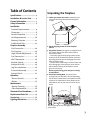
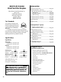
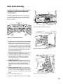
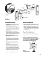
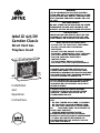
WARNING: IF THE INFORMATION IN THESE INSTRUCTIONS ARE NOT FOLLOWED EXACTLY, A FIRE OR EXPLOSION MAY RESULT CAUSING PROPERTY DAMAGE, PERSONAL INJURY OR LOSS OF LIFE. FOR YOUR SAFETY: DO NOT STORE OR USE GASOLINE OR OTHER FLAMMABLE VAPORS AND LIQUIDS IN THE VICINITY OF THIS OR ANY OTHER APPLIANCE. INSTALLATION: INSTALLATION AND SERVICE MUST BE PERFORMED BY A QUALIFIED INSTALLER, SERVICE AGENCY OR LICENSED GAS SUPPLIER. Jøtul GI 425 DV Camden Classic Direct Vent Gas Fireplace Insert • • • • • WHAT TO DO IF YOU SMELL GAS: DO NOT TRY TO LIGHT ANY APPLIANCE. DO NOT TOUCH ANY ELECTRICAL SWITCHES. DO NOT USE THE PHONE IN YOUR BUILDING. IMMEDIATELY CALL YOUR GAS SUPPLIER FROM A NEIGHBOR’S PHONE. FOLLOW YOUR GAS SUPPLIER’S INSTRUCTIONS. IF YOU CANNOT REACH YOUR GAS SUPPLIER, CALL THE FIRE DEPARTMENT. AVERTISSEMENT: ASSUREZ-VOUS DE BIEN SUIVRE LES INSTRUCTIONS DANS CETTE NOTICE POUR REDUIRE AU MINIMUM LE RISQUE D’INCENDIE OU POUR EVITER TOUT DOMMAGE MATERIEL, TOUTE BLESSURE OU MORTALIT’E. Installation and Operation Instructions NE PAS ENTREPOSER NI UTILISER D’ESSENCE NI OU LIQUIDES INFLAMMABLES DANS LE VOISINAGE DE CET APPAREIL OU DE TOUT AUTRE APPAREIL. L’INSTALLATION LE SERVICE DOIVENT ETRE EXECUTES PAR UN INSTALLATEUR QUALIFIE, AGENCE DE SERVICE OU LE FOURNISSEUR DE GAZ. QUE FAIRE SI VOUS SENTEZ UNE ODEUR DE GAZ. • NE PAS TENTER D’ALLUMER L’APPAREIL • NE TOUCHEZ A AUCUM NTERRUPTEUR. • NE PAS VOUS SERVIR DES TELEPHONES SE TROUVANT DANS LE BATIMENT OU VOUS VOUS TROUVEZ. • APPELEZ IMMEDIATEMENT VOTRE FOURNISSEUR DE GAZ CHEZ UN VOISIN. SUIVEZ LES INSTRUCTIONS DU FOURNISSEUR. • SI VOUS NE POUVEZ REJOINDRE LE FOURNISSEUR DE GAZ, APPELEZ LE SERVICE DES INCENDIES. Welcome to Jøtul... Congratulations on the purchase of your new Jøtul GI 425 DV Camden Classic Gas Fireplace. We at Jøtul are glad you’ve made the decision to warm your hearth with one of our products. We’ve been making fine quality cast iron stoves and fireplaces continuously since 1853. Your new Camden fireplace is the result of our experience as the world’s largest manufacturer of solid fuel burning appliances for over 150 years. In the GI 425 DV Camden Classic, we’ve combined advanced gas technology with the warm, traditional elements of cast iron. With proper care and use, your Jøtul fireplace will provide you with many years of safe, dependable and satisfying service. The GI 425 DV Camden Classic is a direct vented gas heater designed and approved for installation into an existing masonry fireplace. Please take a few minutes to familiarize yourself with this manual and the features of your new gas fireplace. PLEASE READ THESE INSTRUCTIONS IN THEIR ENTIRETY AND MAKE THEM AVAILABLE TO ANYONE USING OR SERVICING THIS APPLIANCE. THIS PRODUCT MUST BE INSTALLED BY A LICENSED MASTER OR JOURNEYMAN PLUMBER OR GAS-FITTER WHEN INSTALLED IN THE COMMONWEALTH OF MASSACHUSETTS. 2 Table of Contents Specifications ............................. 4 Installation & Service Tools .......... 4 General Information ................... 5 Safety Information.......................... 6 Installation Fireplace Requirements ............ 4 Clearances ....................................... 8 Hearth Protection ......................... 9 Vent Requirements ..................... 10 Masonry Fireplace ....................... 11 Prefabricated Fire ........................ 12 Fireplace Assembly Gas Connection ............................ 14 Gas Pressure .................................. 14 High Altitude Adjustment ........ 15 Fuel Conversion ............................ 16 Wall Thermostat .......................... 18 Remote Control ............................ 18 Antique Brick Kit .......................... 19 Log Set Installation ..................... 20 Surround Assembly ..................... 21 System Check ................................ 22 Operation Burner Controls ........................... 24 Blower ............................................ 25 Maintenance Annual Cleaning ......................... 26 Glass Replacement ..................... 26 Illustrated Part Breakdown ...... 28 Unpacking the Fireplace 1. Before you remove the carton, remove the cast iron parts that are packed around the fireplace firebox. 2. Lift the shipping carton off of the fireplace cabinet. 3. Unpack the Firebox. The Logset is packaged inside the firebox. Remove the Glass Panel Frame to unpack the firebox: • Locate the right and left spring latches on the underside of the firebox floor. Release each latch by pulling them forward to disengage the Frame from the Firebox body. • Pull the Glass Frame away from the Firebox and lift to disengage it from the three steel retainer tabs located at the top of the firebox. Set the glass out of the way. Do not unpack the log parts until you are ready to install them. 4. Install the Levelling Bolts. Five round head carriage bolts are included in the Hardware Bag. Tilt the insert cabinet back on the pallet to allow clearance for installation of these bolts into the Cabinet Base, one at each corner and one in the center. Spring Latch Replacement Parts List ............. 29 Service Log ................................ 30 Lighting Instructions ................ 31 Pull each Spring Latch to disengage them from the Glass Frame. 3 Jøtul GI 425 Camden Direct Vent Gas Fireplace Manufactured and Distributed by: Jøtul A.S.A. Fredrikstad, Norway Jøtul North America Gorham, Maine Accessories Antique Brick Panel Kit ....................................... #155311 Wide Surround Kit - Cast Iron Max. Opening Overlap: 47” Wide x 33 1/2” High. Matte Black ................................................... #155323 Blue Black Enamel ....................................... #155324 Jøtul Iron Gray .............................................. #155354 Fuel Conversion Kit - NG to LP ......................... #155300 Fuel Conversion Kit - LP to NG ......................... #155303 MEA No. 369-04-E Wall Thermostat ................................................... #750003 Remote Control ..................................................... #129706 Test Standards This appliance complies with National Safety standards and is tested and listed by Intertek Testing Services of Middleton, Wisconsin. In addition, the Jøtul GI 425 DV gas fireplace insert has been tested and listed as a direct vent gas fireplace heater and listed to ANSI Z21.88-1998 (NFPA 54) and CSA 2.33-M98 for Canada. Jøtul QuickFace™ System Rectangular Frame w/ Screen, Brushed Stainless Steel ............................. #155312 Arched Frame w/ Screen, Brushed Stainless Steel ............................. #155313 Rectangular Frame w/ Screen, Matte Black ................................................... #155314 Arched Frame w/ Screen, Matte Black ................................................... #155315 Specifications Double Doors, Cast Iron Matte Black ................................................... #350565 Input Rates Double Doors, Cast Iron Blue Black Enamel ....................................... #350566 Natural Gas 26,000 BTU/hr. maximum input 13,000 BTU/hr. minimum input Propane Suggested Tools for Installation and Service 26,000 BTU/hr. maximum input 13,000 BTU/hr. minimum input Inlet Pressure: MIN Natural Gas: 5.0 WC (1.24 kPa) Propane: 12.0 WC (2.98 kPa) Manifold Pressure: MIN Natural Gas: 1.2 WC (0.29 kPa) Propane: 2.9 WC (0.72 kPa) MAX 7.0 WC (1.74 kPa) 14.0 WC (3.48 kPa) MAX 3.8 WC (0.95 kPa) 11.0 WC (2.74 kPa) Steady State Efficiency: 77.3% A.F.U.E. Efficiency: 67.9% Piezo Ignitor / Standing Pilot THIS FIREPLACE IS SHIPPED AS A NATURAL GAS FIREPLACE ONLY. IF USE WITH PROPANE IS DESIRED, THE FIREPLACE MUST BE CONVERTED TO USE WITH PROPANE. FOR YOUR CONVENIENCE THIS FIREPLACE IS SHIPPED WITH A PROPANE CONVERSION KIT. 4 • • • • • • • • • • • • • • • • • External regulator (for Propane only) Piping which complies with local code Manual shutoff valve - T-Handle in Massachusetts Sediment trap - if required by code Tee joint Pipe wrench Pipe sealant 10mm open end wrench 1/2”, 7/16” open end wrench Phillips head screwdriver Flat head screwdriver 1/4” nut driver Gloves Safety glasses Torx T20 screwdriver Leak test solution Power Drill General Information IMPORTANT: SAVE THESE INSTRUCTIONS. THIS HEATER MUST BE INSTALLED AND MAINTAINED BY A QUALIFIED SERVICE AGENCY. DO NOT ATTEMPT TO ALTER OR MODIFY THE CONSTRUCTION OF THIS APPLIANCE OR ITS COMPONENTS. ANY MODIFICATION OR ALTERATION WILL VOID THE WARRANTY, CERTIFICATION AND LISTING OF THIS APPLIANCE. 1. The installation and repair of this appliance must be done by a qualified service person. Failure to properly install and maintain this heater could result in an unsafe or hazardous installation, which may result in a fire, explosion, property damage, personal injury or loss of life. 2. This appliance should be inspected before use and at least annually. More frequent cleaning may be required due to excessive lint from carpeting, bedding material, etc. It is imperative that control compartments, burners and circulating air passageways of the appliance be kept clean. 4. DO NOT OPERATE THIS FIREPLACE IF ANY PART HAS BEEN UNDER WATER. Immediately call a qualified service technician to inspect the heater and to replace any part of the control system and any gas control which has been under water. Ne pas se servir de cet appareil s’il a ete’ plonge dans l’eau, completement ou en partie. Appeler un technicien qualifie pour inspecter l’appareil et remplacer toute partie du syste’me de controle et toute commande qui ont ete plonges dans l’eau. 5. Do not operate the fireplace with the glass front removed, cracked or broken. Replacement of the glass should be done by a licensed or qualified service person. Only remove glass for routine service. Always handle glass carefully. Pour utilisation avec les portes en verre cerifiers aved l’appareil seulemend ou. Ne pas utiliser avec des portes on verre. 6. Notify your insurance company before proceding with installation of this fireplace. `S’assurer que le bruleur et le compartiment des commandes sont propres. Voir les instructions d’installation et d’utilisation qui accompagnent l’appareil. 3. The installation must conform to local codes. Your local Jøtul authorized dealer can assist you in determining what is required in your area for a safe and legal installation. Some areas require a permit to install a gas burning appliance. Always consult your local building inspector or authority having jurisdiction to determine what regulations apply in your area. In the absence of local codes, the installation requirements must comply with the current National codes. In the U.S., these requirements are established in the National Fuel Code, ANSI Z223.1.(NFPA 54). In Canada, the codes have been established in CAN/CGA B149 Fuel Installation Code. Installer l’appareil selon les codes ou reglements locaux, ou, en l’absence de tels reglements, selon les Codes d’installation CAN/CGA-B149. 5 Safety Information Due to the high operating temperatures this appliance should be located out of traffic and away from furniture, draperies, etc. Maintain proper clearance to combustible mantels and fireplace trim. Children and adults should be alerted to the hazards of high surface temperatures and should stay away to avoid burns or clothing ignition. Young children should be supervised while they are in the same room as the GI425 gas fireplace. Surveiller les enfants. Garder les vetements, les meubles, l’essence ou autres liquides a vapeur inflammables loin de l’appareil. Clothing or other flammable materials should not be placed ON or NEAR the GI425 gas fireplace. Never allow any to use the fireplace if they are unfamiliar with its operation. NEVER store or use gasoline or any other flammable vapors or liquids in the vicinity of the GI425 gas fireplace. Never burn any solid materials (wood, cardboard, paper, coal, etc.) in this gas fireplace. Use with natural gas or propane fuel ONLY. Any safety screen, glass or guard removed for servicing the appliance must be replaced prior to operating the appliance. Do not slam or strike the glass panel. Were gloves and safety glases while performing maintenance procedures. Electrical Hazard Be aware of electrical wiring locations when cutting holes in walls and ceilings for termination. The GI425 Blower must be electrically grounded in accordance with local codes or, in the absence of local codes, with the current ANSI/NFPA 70, National Electrical Code or CSA C22.1-Canadian Electrical Code. The GI425 Blower is supplied with a three-prong (grounding) plug for protection against shock hazard and should be plugged directly into a properly grounded three-prong receptacle. DO NOT CUT OR REMOVE THE GROUNDING PRONG FROM THE PLUG. Always disconect the power supply when per- 6 forming routine service on the fireplace. Installation Requirements The GI425 DV Camden Gas Insert can be installed in most solid fuel burning fireplaces of either masonry construction or a prefabricated factory built fireplace. Prior to any installation of the GI425 DV Camden the existing chimney exhaust flue must be thoroughly cleaned and completely inspected by a qualified chimney sweep or fireplace service person. Do not install this insert into a chimney that is damaged. Any repairs must be made prior to installing the insert. If you are unsure of the condition of your fireplace and chimney, contact a professional fireplace technician or your local authorized Jøtul dealer for professional assistance. DO NOT REMOVE BRICKS OR MORTAR FROM THE FIREPLACE OR CHIMNEY STRUCTURE. However, masonry or steel may be removed from the smoke shelf and adjacent damper frame area to accommodate installation of a chimney liner, provided that their removal will not weaken the structure of the fireplace or chimney, and will not reduce protection for combustible materials. If the fireplace has been modified to accommodate installation, use anchors or masonry nails to attach the metal Fireplace Conversion Notice Plate to the back wall of the masonry fireplace firebox where it will be readily seen should the insert be removed. THIS APPLIANCE MUST NOT BE CONNECTED TO A CHIMNEY OR FLUE SERVING ANY OTHER APPLIANCE OF ANY KIND. All venting components must be installed in accordance with the terms of their listing and manufacturer’s instructions. Refer to the pipe manufacturer’s instructions for proper pipe clearances. This fireplace insert is specifically designed for use with 3” Type B vent pipe components or a Listed Flexible gas liner. Do not modify or alter the construction of the gas insert or any of its components to enable it to fit into a fireplace. Any modification of the insert will void the warranty, certifications and approvals of the unit and could be dangerous. 25 635 mm 20 508 mm Air Intake 7 1/2 191 mm Exhaust Outlet 11 289 mm 13 330 mm 8 1/2 (216 mm) 1 1/2 38mm 2 50 mm Exhaust Outlet 30 1/4 768 mm Air Intake 22 559 mm 17 432 mm 5 127 mm 40 1016 mm 21 1/2 546 mm Figure 1. GI 425 DV dimensions. Minimum Fireplace Requirements The GI425 DV CAMDEN gas insert has been specifically designed to be installed into a solid fuel burning factory built fireplace OR a code approved solid fuel burning masonry fireplace with a tile flue liner. An acceptable fireplace cavity must have the minimum dimensions specified below. E D B C A A: Opening Width = 28” (711 mm) B: Opening Height = 22” (559 mm) C: Back Wall Width = 20” (508 mm) D: Back Wall Height = 20” (508 mm) E: Depth = 13” (330 mm) Figure 2. Minimum fireplace cavity dimensions. Surround Hangers 22 559 mm Min. Opening Height 28 711 mm Min. Opening Width for Surround Hanger Clearance Figure 3. Minimum opening clearance. Optional Lattice Surround shown. 7 Covering the Fireplace Opening Clearance Requirements Two cast iron surround styles are available for the GI 425 Camden fireplace insert. The following clearances and hearth requirements are the minimum requirements when installing the Camden gas insert into a solid fuel burning appliance. These dimensions are measured from the firebox cabinet to the combustible material. See figures 5 and 6. A combustible surface is anything that can burn (i.e. sheet rock, wallpaper, wood, fabrics etc.). These surfaces are not limited to those that are visible and also include materials that are behind non-combustibles. Standard Classic Surround The GI425 Camden includes Surround Panels that will overlap a maximum fireplace opening 39” Wide x 29 1/2” High. The actual standard surround dimensions are 40” Wide x 30 1/4” High. Optional Lattice Classic Surround The Lattice Surround Kit shares the same dimensions as the standard Classic Surround described above. #350557 - Matte Black #350558 - Blue Black. #350559 - Jøtul Iron Optional Wide Surround #155323 - Matte Black #155324 - Blue Black. #155354 - Jøtul Iron These optional panels can be used to extend the Classic or Lattice surround panels to cover oversize fireplace openings up to a maximum 47” Wide x 33 1/2” High. The actual wide surround dimensions are 48” Wide x 34” High. NOTE: The additional weight of the Wide Surround may necessitate use of the Anchor Bracket which is included with this fireplace. The anchor will ensure that the surround assembly aligns properly against the fireplace face. Use the installation instructions included in the Hardware bag. If you are not sure of the combustible nature of a material, consult your local fire officials. Remember, “Fire Resistant” materials are considered combustible: they are difficult to ignite, but will burn. Also, “fire-rated” sheet rock is considered combustible. Always maintain the proper clearances to the appliance for the proper flow of ventilation air around the insert. Figure 5. Clearance to Adjacent Combustible Material - measured from the fireplace centerline or hearth. F 48 1219 mm E B 34 864 mm Figure 4. Wide Surround Dimensions. SEE PAGE 21 FOR SURROUND PANEL ASSEMBLY INSTRUCTIONS. 8 C A D A: Hearth Protection Width - None required B: Hearth Protection Depth - None required C: Side Trim Clearance, 1” thick (25 mm) = 21 3/4 in. (552 mm) D: Side Room Wall Clearance = 39 3/4 in. (1010mm) E: Top Trim Clearance = 39 1/2 in. (1003 mm) F: Mantel Clearance at 9 in. max. depth = 47 in. (1194 mm) Mantel Clearance at 3.5 in. max. depth = 41 1/2 in. (1054 mm) Mantel and Trim Clearance 9 228 mm 8 6 1/2 5 3 1/2 21 1/2 622 mm 27 1/2 736 mm UPPER TRIM 1 Max. Depth 19 1/2 508 mm 25 1/2 698 mm 23 1/2 660 mm 17 1/2 394 mm TOP OF FIREBOX CABINET 22 559 mm Figure 6. Minimum Mantel Clearances. Measure clearances from the top and sides of the fireplace cabinet before installation of the cast iron surround panels. Hearth Requirements The Jøtul GI425 Camden does not require special hearth protection. Combustible flooring materials may be present directly in front of the fireplace insert. 9 Vent Guidelines • All vent components must be installed in accordance with the listing terms and manufacturer’s instructions. • Vent Height: Measured from the top of the insert to the top of the termination cap. Minimum: no less than 10' Maximum: no greater than 35'. See figures 9 and 10. The minimum vent height above the roof or adjacent walls is specified by building codes. As a general guide, follow the Gas Vent Rule on page 12. • HORIZONTAL RUNS ARE NOT PERMITTED ANYWHERE IN THE VENTING SYSTEM. • Venting liners used on this appliance may not be less than 3” in diameter or greater than 3” in diameter. • Any unused flue or masonry enclosure can be used as a passageway for venting provided the flue is relined using 3” Listed flexible gas liner. • The remaining space around the liner in a masonry or zero-clearance flue CANNOT be used to vent any other appliance. • Flexible liner components may not be exposed in any living space. • Installation of any components not manufactured or approved by Jøtul or failure to meet all clearance requirements will void all warranties and could result in property damage, bodily injury, or serious fire. • Never modify any venting component, or use any damaged venting product. • THE GAS APPLIANCE AND VENT SYSTEM MUST BE VENTED DIRECTLY TO THE OUTSIDE OF THE BUILDING, AND NEVER ATTACHED TO A CHIMNEY SERVING A SOLID FUEL OR GAS BURNING APPLIANCE. • Variable Vent Restriction: See the System Check section on pages 22-23 for specific instructions. IMPORTANT NOTICE: THE USE OF AN EXISTING CHIMNEY AS AN AIR INTAKE IS NOT COVERED UNDER THE ANSI Z21.88-1999-CSA 2.33M99 TEST METHODS AND RESULTING ITS/WHI PRODUCT CERTIFICATION. THE CODE AUTHORITY HAVING JURISDICTION MUST BE CONSULTED PRIOR TO PROCEEDING WITH THIS INSTALLATION METHOD. 10 Masonry Fireplace Installation When installing a GI425 DV Camden gas insert into a masonry fireplace the insert will be vented through dual 3” flexible gas aluminum liners. This co-linear installation includes a pair of 3” flex ducts that run from the insert completely through the existing chimney to the termination cap. One liner is attached to the Exhaust Outlet on the back of the unit and will carry the exhaust gases to the outside of the house. This exhaust liner must be directly connected to the unit and run the full length of the chimney. See figure 7. The other 3” liner will be attached to the Air Intake Collar on the back of the unit to provide fresh air for combustion. The Intake Collar is labeled for easy identification. The liner must extend a minimum of 6’ off the back of the unit and extend through the damper area of the fireplace into the tile liner of the chimney. This liner can also extend the full length of the chimney and connect to the termination cap. IMPORTANT If the intake flex does not extend the full length of the chimney, forming a direct connection between the unit and the termination cap, A METAL BLOCK OFF PLATE MUST BE INSTALLED to seal the air intake from room air. Normally this sealing plate will be installed within the existing fireplace damper area. See figure 7. The sealing plate is not necessary if a direct connection is made between the cap and the fireplace. WARNING! Avoid cross venting the insert. Before installation, label both ends of the exhaust flex pipe to ensure connection to the appropriate collars on the fireplace unit and vent termination cap. CANADA REQUIREMENT: Both the Intake and the Exhaust liners must extend the full length of the chimney and be securely connected to both the unit and the termination kit. If the fireplace has been modified to accommodate installation, use anchors or masonry nails to attach the metal Fireplace Conversion Notice Plate supplied with this unit to the back wall of the masonry fireplace firebox where it will be readily seen should the insert be removed. Venting through a Masonry Fireplace 1. Measure height of the chimney to fireplace opening. Determine if both the intake and exhaust will be extended to the top of the chimney. Listed Direct Vent Termination Cap 2. Use tin snips to cut the appropriate lengths of flex for both the intake and exhaust. 123456789 123456789 123456789 Sealed Chimney Cap Anchor Plate 3. Attach the appropriate ends of the flex to the chimney termination kit. 4. Drop the liners down the chimney from the top and rest the termination kit atop the chimney. 5. Seal the chimney termination kit to the top of the chimney flue with high temperature sealant. EXHAUST FLEX PIPE 6. Secure the appropriate DIRECT VENT CAP to the termination kit. 7. Inside the fireplace, fully extend the flex liner pipe and cut off the excess so that the liners hang approximately 15” from the floor of the fireplace. a. It will be necessary to install a minimum length of 6 ft. flex pipe up into the flue. b. A metal damper block off plate must be constructed and installed in the fireplace damper area to completely seal off the flue from the room. Cut holes in the plate for both the intake and exhaust flex pipes. c. A direct vent cap is required to bring fresh air into the chimney flue and Air Intake flex pipe. d. Compress the liners so that they are hanging out of the way above the fireplace opening. e. Attach the Fireplace Conversion Notice to the back of the fireplace if appropriate. 9. Position the insert without surround panels halfway inside the fireplace and attach the liners to the appropriate ports on the rear of the stove. Be sure not to cross vent these connections. Secure the liners to the ports using sheet metal screws or hose clamps. No silicone or sealant is required. WARNING: FAILURE TO POSITION THE PARTS IN ACCORDANCE WITH THIS DIAGRAM OR FAILURE TO USE ONLY PARTS SPECIFICALLY APPROVED WITH THIS APPLIANCE MAY RESULT IN PROPERTY DAMAGE OR PERSONAL INJURY. Listed Flexible Gas Liners Max. Height 35 ft. AIR INTAKE FLEX PIPE 8. If the Air Intake pipe will not be attached to the chimney termination kit: (See NOTICE on page 10. ) Min. Height 10ft. Maintain proper clearance to Mantel and Trim Metal block-off plate is required to seal flue from the living area if Air Intake pipe does not connect directly to a Direct Vent Termination at the top of the chimney To Exhaust Collar Attach Fireplace Conversion Notice Plate to Rear Wall of Fireplaceif the damper has been modified. To Air Intake Collar Figure 7. Masonry Fireplace Venting Configuration. 11 Prefabricated Fireplace Installation A factory-built prefabricated fireplace will require a few modifications before installation of the Jøtul GI425 Camden fireplace insert. Modification Steps: 1. Remove any fuel grate or other components attached attached to the firebox. On most models the firegrate is attached to the unit with brackets which should be cut or pried off. 2. Remove the damper assembly. This includes the damper blade, handle and any linkage. Two 3” liners must be able to pass through the damper area. 3. Remove any firescreen or door assembly. This is usually done by removing a support rod on the inside of the fireplace frame. 4. If there is a metal ashlip, it too should be removed to allow the unit to sit flat in the fireplace. Be sure to reinstall any screws removed. IMPORTANT: BEFORE STARTING THIS INSTALLATION, MAKE SURE THAT A GAS LINE CAN BE INSTALLED OR IS INSTALLED TO THE FIREBOX. THIS SHOULD ONLY BE DONE BY A QUALIFIED OR LICENSED PLUMBER OR GAS FITTER. The GI425 DV Camden gas insert is specifically designed to be vented using a co-linear system. Installation includes a pair of 3” flex ducts that run from the insert completely through the existing chimney to the termination cap. See figure 8. One liner is attached to the exhaust port on the back of the unit and will carry the exhaust gases to the outside of the house. This exhaust liner must be directly connected to the unit and run the full length of the chimney. IMPORTANT NOTICE: THE USE OF AN EXISTING CHIMNEY AS AN AIR INTAKE IS NOT COVERED UNDER THE ANSI Z21.88-1999-CSA 2.33M99 TEST METHODS AND RESULTING ITS/WHI PRODUCT CERTIFICATION. THE CODE AUTHORITY HAVING JURISDICTION MUST BE CONSULTED PRIOR TO PROCEEDING WITH THIS INSTALLATION METHOD. 12 The other 3” liner will be attached to the intake port on the back of the unit and will provide fresh air for combustion to the unit. This liner must extend a minimum of 6’ off the back of the unit and extend through the damper area of the fireplace and into the first section of pipe. This liner can also extend the full length of the chimney and connect to the termination cap. See figure 10. IMPORTANT: If the intake flex does not extend the full length of the chimney and connect to the unit and the termination cap - THEN A METAL BLOCK OFF PLATE MUST BE CONSTRUCTED AND INSTALLED ABOVE THE UNIT PRIOR TO THE END OF THE INTAKE FLEX (normally at the damper area). To avoid cross venting the insert- always label the flex to be used for the exhaust conduit at both the top and bottom ends of the flex. This ensures that the exhaust flex is installed to the proper outlet on the chimney termination kit. The minimum vent height above the roof or adjacent walls is specified by major building codes. A general guide to follow is the Gas Vent Rule below. GAS VENT RULE ROOF SLOPE Minimum Height From Roof Flat to 6/12 1’0” 0.3M Over 7/12 to 9/12 2’0” 0.6M Over 10/12 to 12/12 4’0” 1.2M Over 13/12 to 16/12 6’0” 1.8M Over 17/12 to 21/12 8’0” 2.4M CANADA REQUIREMENT: Both the Intake and the Exhaust liners must extend the full length of the chimney and be securely connected to both the unit and the termination kit. If the fireplace has been modified to accommodate installation, use anchors or masonry nails to attach the metal Fireplace Conversion Notice Plate supplied with this unit to the back wall of the masonry fireplace firebox where it will be readily seen should the insert be removed. Listed Direct Vent Termination Cap 123456789012 EXHAUST FLEX PIPE AIR INTAKE FLEX PIPE 123456789012 123456789012 1234 12345 1234 12345 1234 12345 1234 12345 1234 12345 1234 12345 1234 12345 1234 12345 1234 12345 1234 12345 1234 12345 1234 12345 Factory-built Listed 1234 12345 1234 12345 Gas Chimney 1234 12345 1234 12345 1234 12345 1234 12345 1234 12345 1234 12345 1234 12345 1234 12345 1234 12345 1234 12345 1234 12345 1234 12345 1234 12345 1234 12345 1234 12345 1234 12345 1234 12345 1234 12345 1234 12345 1234 12345 1234 12345 1234 12345 1234 12345 Listed Flexible 1234 12345 1234 12345 Gas Liners 1234 12345 1234 12345 Max. Height 35 ft. 1234 12345 1234 12345 Min. Height 10ft. 1234 12345 1234 12345 1234 12345 1234 12345 1234 12345 1234 12345 1234 12345 1234 12345 1234 12345 1234 12345 1234 12345 1234 12345 INTAKE FLEX MUST 1234 12345 1234 12345 EXTEND A MINIMUM 1234 12345 1234 12345 OF 6’ AND INTO 1234 12345 1234 12345 THE CHIMNEY PIPE 1234 12345 1234 12345 1234 12345 1234 12345 Maintain proper 1234 12345 1234 12345 123456 clearance to Mantel 123456 1234 12345 123456 1234 12345 and Trim 123456 1234 12345 123456 1234 12345 123456 1234 12345 123456 1234 12345 Metal block-off plate is 123456 1234 12345 123456 1234 12345 required to seal flue 123456 1234 12345 from the living area if 123456 1234 12345 1234 12345 Air Intake pipe does not 123456 123456 1234 12345 123456 connect directly to a 123456 Direct Vent Termination 123456 123456 at the top of the 123456 123456 chimney To Exhaust Collar Attach Fireplace Conversion Notice Plate to Rear Wall of Fireplaceif the damper has been modified. To Air Intake Collar 1234567890123456789012 1234567890123456789012 1234567890123456789012 1234567890123456789012 Venting Installation Through a Prefabricated Fireplace 1. Measure height of the chimney to fireplace opening. Determine if both the intake and exhaust will be extended to the top of the chimney. 2. Cut the appropriate lengths of flex for both the intake and exhaust. 3. Attach the appropriate ends of the flex to the chimney termination kit. 4. Drop the liners down the chimney from the top and rest the termination kit atop the chimney. 5. Seal the chimney termination kit to the top of the chimney pipe with high temperature sealant. 6. Secure the appropriate DIRECT VENT CAP to the termination kit. 7. Inside the fireplace, fully extend the flex and cut off the excess flex so that the liners hang approximately 15” from the floor of the fireplace. 8. If the intake flex is not attached to the chimney termination kit: See NOTICE on page 12. A. It is now necessary to install a minimum of a 6 foot length of flex into the flue for the intake air. B. A METAL damper block off plate must be constructed and installed in the damper area to completely seal off the flue from the room. Remember to cut holes for both the intake and exhaust liners in the block off plate. C. A direct vent cap is still required to allow fresh air into the chimney flue and ultimately into the intake flex and insert. D. Attach the Fireplace Conversion Notice to the back of the fireplace if appropriate. 9. Compress the liners so that they are hanging above the height of the fireplace opening and are out of the way. 10. Position the insert without surround panels half-way inside the fireplace and attach the liners to the appropriate ports on the rear of the stove. Be sure not to cross vent the insert. 11. Secure the liners to the ports using sheet metal screws or hose clamps. No silicone or sealant is required. Figure 8. Factory-built Fireplace Vent Configuration. 13 Connecting the Gas Supply Gas Supply Requirements Leak test: ALL INSTALLATIONS MUST COMPLY WITH LOCAL CODE OR IN THE ABSENCE OF LOCAL CODE, MUST COMPLY WITH THE MOST RECENT EDITION OF THE NATIONAL FUEL GAS CODE ANSI Z223.1/NFPA 54 OR CAN-B149. NOTE: INSTALL THE OPTIONAL BLOWER BEFORE PLUMBING THE GAS LINE TO THE VALVE. • Mix a 50-50 solution of water and dish soap. THIS PRODUCT MUST BE INSTALLED BY A LICENSED MASTER OR JOURNEYMAN PLUMBER OR GAS-FITTER WHEN INSTALLED IN THE COMMONWEALTH OF MASSACHUSETTS. Shutoff Valve • Light appliance- see lighting instructions on page 23 of this manual or on the fireplace’s rating plate. • Brush or spray all joints and connections with the soapy water solution. • If bubbles appear at any connection or seam or a gas odor is detected, immediately turn gas control knob to the OFF position. Tighten or reconnect the leaking joint and retest for any gas leaks. All codes require a gas shutoff valve (gas cock) and union to be installed in the supply line and in the same room as the appliance. This allows for the disconnection of the fireplace for servicing and maintenance. See Fig. 9. A T-HANDLE GAS SHUTOFF VALVE IS REQUIRED IN MASSACHUSETTS IN COMPLIANCE WITH CODE 248CMR. The fireplace and gas control valve must be disconnected from the gas supply piping during any pressure testing of the system at test pressures in excess of 1/2 psig. For pressures lower than 1/2 psig, isolate the gas supply by closing the manual shutoff valve. Control Valve Connection The gas supply line connection is made to the left side of the valve. The gas supply line should be a minimum 3/8" diameter, or the appropriate size to provide sufficient gas pressure to the valve regardless of the input setting. The use of flexible gas appliance connectors is acceptable in many areas in the U.S. In Canada, methods vary depending on local code. If local codes permit, use flexible gas line for ease of installation and service. For those locales where flexible gas lines are not permitted, use the 3/8” iron fitting to make the connection at the left side of the Control Valve. See Figures 9 and 10. Secure all joints tightly using appropriate tools and sealing compounds (for propane units, be sure to use compounds that are propane resistant). Turn on gas supply and test for gas leaks using a soapy water solution. Never use an open flame to check for leaks. 14 Figure 9. Gas supply line fittings. Gas Pressure Proper gas pressure provides a consistent flow of gas to the appliance and is instrumental in checking for gas leaks. The gas control valve on the fireplace is equipped with pressure test points for gauge connections. The gauge connections are located on the front of the valve under the On/Off/ Pilot knob. Gauge connections are identified by: • IN/E for inlet or supply pressure (the amount of gas coming to the valve.) • OUT/A for manifold pressure (the amount of gas that is coming out of the valve to the burner.) E A Figure 10. Pressure test point as located on the front of the valve. The appliance must be isolated from the gas supply line by closing its individual manual gas shutoff valve (gas cock) during any pressure testing of the gas supply piping system that is equal to or exceeds pressures of 1/2 psig (3.5 kPa). Inlet Pressure MIN MAX Natural Gas: 5.0 WC (1.24 kPa) 7.0 WC (1.74 kPa) Propane: 12.0 WC (2.98 kPa) 13.0 WC (3.23 kPa) Manifold Pressure MIN MAX Natural Gas: 1.2 WC (0.29 kPa) 3.8 WC (.95 kPa) Propane: 2.9 WC (0.72 kPa) 11.0 WC (2.74 kPa) ALWAYS TEST PRESSURE WITH VALVE CONTROL KNOB SET ON HIGH. Symptoms of incorrect gas pressure include: Insufficient gas pressure: • Small pilot flame which can result in insufficient millivolts. • Little variation in flame picture between HI and LO settings. • Insufficient gas to support more than one appliance causing nuisance outages or gas surges. Excessive gas pressure: • Permanent damage to valve causing complete appliance shut down. • Too large a pilot flame resulting in overheating of the power generator and consequent shut down. • Sooting due to impingement and/or incorrect fuel to air mix. High Altitude Adjustment Installations located at altitudes from 2000 - 4250 ft. (610 M - 1370 M), DONOT require adjustment. Do not derate this appliance for altitude. 15 Fuel Conversion The GI425 Fireplace is designed to for use with either Natural gas or Propane. It is shipped from the factory configured to use Natural gas. A conversion kit is included for conversion to Propane use if desired. Check the identification label on the Control Valve to confirm that the correct fuel is used. Conversion Kit Contents: WARNING: THE CONVERSION KIT IS TO BE INSTALLED BY AN AUTHORIZED JØTUL SERVICE TECHNICIAN IN ACCORDANCE WITH THE MANUFACTURER’S INSTRUCTION AND ALL CODES AND REQUIREMENTS OF THE AUTHORITY HAVING JURISDICTION. FAILURE TO FOLLOW THESE INSTRUCTIONS COULD RESULT IN SERIOUS INJURY OR PROPERTY DAMAGE. THE QUALIFIED AGENCY PERFORMING THIS WORK ASSUMES RESPONSIBILITY FOR THIS CONVERSION. • 1 Pilot Orifice (#30 for LP, #51 for NG) IN CANADA: THE CONVERSION SHALL BE CARRIED OUT IN ACCORDANCE WITH THE REQUIREMENTS OF THE PROVINCIAL AUTHORITIES HAVING JURISDICTION AND IN ACCORDANCE WITH THE REQUIREMENTS OF THE CAN1-B149.1 AND .2 INSTALLATION CODE. #155300 - LP #155303 - NG • 1 Regulator Tower labeled for Propane • 3 Regulator Tower Screws • 1 Burner Orifice (3/32” NG, 1.45 mm LP) • Label A - to be completed and applied to the control valve. • Label B - apply to the fireplace Rating Plate as designated on the plate. WARNING: If appropriate, be sure to unplug the blower before proceeding with this conversion. Fuel Conversion Procedure 1. Remove the Glass Frame: • Release the two frame latches and lift the frame up off of the retainer tabs at the top of the firebox. 2. Empty the firebox: • Lift and remove the Fettle and Logset package. CAUTION: THE LOGS ARE FRAGILE. Handle them with care and set aside out of the way. • Remove the Logset Base by lifting it out of the firebox. Cet equipement de conversion sera installe par une agence qualifiee de service conformement aux instructions du fabricant et toutes exigences et codes applicables de l’autorises avoir la juridiction. Si l’information dans cette Instruction n’est pas suivie exactement, un fey, explosion ou production de protoxyde de carbone peut resulter blessure personnelle de vie. L’agence qualifiee de service est esponsable de l’installation n’est pas propre et complete jusqu’a l’operation de l’appareil converti est cheque suivant les criteres etablis dans les instructions de proprietaire provisionnees avec l’equipement. 3. Change the Burner Orifice: Tools required: 4. Change the Pilot Orifice: 1/4” Nut driver, 7/16” and 1/2” open end wrench or deep well socket, 4 mm allen wrench, Torx t20 or slotted screwdriver. 16 • Loosen the locknut on the Air Shutter Stem, located under the firebox floor to the right of the Control Valve. This will allow you to disengage the Burner Tube. Fig. 11. • Lift the rear of the Burner Tube and rotate slightly forward. Slide the tube to the left enough to disengage it from the Air Shutter and Burner Orifice, then lift out. Slide the Air Shutter back out of the way to expose the orifice. Fig. 12. • Using a ½” open end wrench or deep well socket remove the burner orifice and replace with the appropriate orifice, supplied in the kit. • FROM WITHIN THE FIREBOX, disengage the Pilot Hood by releasing the retainer clip as shown in Fig. 13. Using a 4 mm allen wrench, unscrew the pilot orifice (counter clockwise). Replace with the appropriate orifice: #51 for Natural gas #30 for Propane Tighten new orifice into the base of the pilot assembly. • Replace Pilot Hood by pushing it into the base. 5. Replace the Burner Tube:. Slip the end of the tube into the Air Shutter and SLIDE TUBE TO THE RIGHT TO COMPLETELY COVER THE ORIFICE. 6. Adjust the Air Shutter: See Fig. 31. • Slide the shutter forward (toward yourself) to open the inlet. Slide it back to the rear to close. The standard settings are: Natural gas - 1/4” open Propane - 1/2” open 7. Change the Regulator: See Fig. 14. Air Shutter Wingnut Pull Frame Spring Latch to release. • Using a Torx T-20 screwdriver or small flat head screwdriver, remove the three specialty screws from the front of the valve regulator. • Remove the regulator tower and gasket. BE SURE TO REMOVE THE BLACK RUBBER GASKET FROM THE VALVE. OPEN • Install the new variable regulator tower with the new rubber gasket. Thoroughly tighten new regulator to valve body. CLOSED 8. Apply the Conversion Labels: Figure 11. Frame latch and air shutter stem location. Injector Air Shutter • Apply LABEL A to the cabinet floor so that it may be seen by anyone servicing the fireplace. • Apply LABEL B to the Rating Plate in the space provided. 9. Reassemble the fireplace, apply gas to the system and check for gas leaks including all gas lines before and after the valve. NEVER USE AN OPEN FLAME TO CHECK FOR GAS LEAKS. IMPORTANT: Correct gas pressure is essential for efficient and safe operation. It is important that the correct gas pressure be established at the time of the installation. For more details, see the Gas Pressure section of this manual on page 14. Burner Orifice Stem Figure 12. Burner orifice removal and replacement. Pilot Hood Pilot Orifice Retainer Clip WHEN LIGHTING THIS APPLIANCE, ALWAYS REFER TO THE LIGHTING INSTRUCTIONS ON THE BACK COVER OF THIS MANUAL. BE SURE TO REMOVE THE BLACK RUBBER GASKET FROM THE VALVE. PILOT ASSEMBLY Figure 13. Pilot Orifice replacement. Figure 14 Valve Regulator replacement. 17 Wall Thermostat Installation Remote Control Use Jøtul Thermostat #129706 or a 750 millivolt DC two-wire circuit thermostat to automatically control your fireplace operation. The thermostat should be placed in the same room as the heater, typically 5’ off the floor. Avoid drafty areas or any area that may affect the accuracy of the thermostat. The thermostat should be connected to the GI425 using a minimum of 16 gauge wire with a maximum length of 35 feet of wire. The optional Jøtul Remote Control can be installed on the GI425 gas fireplace. Using the wire supplied with the remote, connect the remote directly to the gas control valve. Connect one receiver lead to the terminal labelled TH. Connect the other receiver lead to the terminal labeled TH/TP. DO NOT DISCONNECT ANY OTHER WIRES FROM THE VALVE, AND DO NOT OVER TIGHTEN THE TERMINAL SCREWS. Connect the two thermostat wire leads to the two lower terminals on the terminal block located to the right of the ON/OFF/T’STAT switch. Do not overtighten the connections. IT IS NOT NECESSARY TO DISCONNECT ANY OTHER WIRES. See Figure 16. Place the receiver unit under the control valve on the floor of the fireplace cabinet. At the thermostat, the two wires should be connected to the two connections screw on the thermostat base plate per the manufacturer’s instructions. For thermostatic function, place the ON/OFF/T-STAT switch in the T-STAT position and the pilot flame must be lit. THERMOPILE ROCKER SWITCH ON TH OFF TP STAT TH TP OPTIONAL THERMOSTAT or REMOTE CONTROL VALVE TERMINAL BLOCK Figure 16. GI425 Valve Wiring Diagram 18 CAUTION: LABEL ALL WIRES PRIOR TO DISCONNECTION WHEN SERVICING THE CONTROLS. WIRING ERRORS CAN CAUSE IMPROPER AND DANGEROUS OPERATION. ALWAYS VERIFY PROPER OPERATION AFTER SERVICING THE APPLIANCE. ATTENTION: AU MOMENT DE L’ENTRETIENDES COMMANDES, ETIQUETEZ TOUS LES FILS AVANT LE DEBRANCHEMENT. DES ERREURS DE CABLAGE PEUVENT ENTRAIUN FONCTIONNEMENT INADEQUAT ET DAGEREUX. Brick Panel Assembly CAUTION: THESE PANELS ARE EXTREMELY FRAGILE! SUPPORT EACH PIECE WITH BOTH HANDS AND HANDLE TENDERLY. Install the optional Brick Panel Kit 155311 before placing the Logset. Place the panels in position in the order as numbered in Fig. 17. No fasteners or tools are required. Upper Rear Panel, 220515 Pull Frame Latches to Release Frame 4 3 Figure 18. Glass Frame latch locations. 2 1 Lower Rear Panel, 220514 Left Side Panel, 220516 Right Side Panel, 220517 Figure 17. Panel installation order. 1. Remove the Glass Frame, if you have not already done so. Remove the Ashlip and locate the two frame latches under the firebox floor. See Fig. 18. Pull the latch handles forward to disengage them from the bottom of the glass frame. You can then pull the frame out and up off of the three retainer tabs at the top of the firebox opening. Set the Glass Frame out of the way. Logset Base Figure 19. Install Lower Rear Panel. 2. Remove the Fettle and Logset. These parts are not fastened. Simply lift them out of the firebox. 3. Install the Lower Rear Panel. Orient the panel so that the cutout is at the bottom. Engage the bottom edge between the rear wall and the firebox base. See Fig. 17. 4. Install the Side Panels. Engage the bottom edge of each side panel between the Logset Base and the firebox wall and push the panel forward against the front lip of the firebox opening. See Fig.20. 5. Install the Upper Rear Panel. This will also be a snug fit. Set the panel up high and then carefully lower it to seat its lower edge against the top of the other rear panel. The side panels will hold it in place. 6. Install the Logset (see pg. 20). Side Panel Figure 20. Install the Side Panel. 7. Replace the Fettle, Andirons and Glass Assembly. 19 Logset Assembly This is the heart of your Jøtul GI 425 Camden fireplace. Much time and effort has been devoted to attaining a lively, realistic flame picture while simultaneously achieving efficient fuel combustion and effective heat output under a variety of installation conditions. The flame picture you experience, however, will be affected by a number of variables peculiar to your installation such as venting configuration, environmental and weather conditions, and fuel type. Log placement is critical to the final flame picture. Pay particular attention to placing the log pieces as illustrated here. Carefully unpack and arrange the logs as outlined below. CAUTION: The logs are fragile. Please handle each piece with care. Center Log Right Log Left Log Rear Log Use safety gloves to handle the log parts as the ceramic fibers can irritate skin. Ceramic Base Figure 21. Logset Parts. 1. Place the Rear Log in position on Ceramic Base pegs as shown in fig. 22. The base is already installed in the fireplace. 2. Set the Right, Left, and Center Logs on the appropriate pegs as shown in fig. 23. 3. Lightly scatter the Platinum Ember material (included in the Miscellaneous Hardware Bag) over the forward area of the Logset Base. Place them directly on top of the burner base and around the log parts. With a little experimentation, you will find that they add an inviting, glowing ember effect after the burner has been operating for a few minutes. 4. Replace the Glass Panel Frame: Engage the top of the frame with the three tabs at the top of the firebox. Push the bottom of the frame against the firebox face and pull the Frame Latches out to engage them with the slots in the bottom of the frame. Figure 22. Engage Rear Log with Base pegs. Loosely scatter Ember material over the burner screen and around the front log pieces. Figure 23. Install the Center, Left and Right Logs on the pegs. 20 Left Breastplate Right Breastplate M6 x 12 Hex Bolt, (2) M6 x 10 Hex Bolt, (2) Set Screw Plumb Adjustment Shim (2) Left Leg Right Leg Figure 24. Assemble the Surround Panels. Hanger Tabs, 4 (pre-installed) Surround Assembly Blower Installation 1. Layout the parts. Place the castings face down on a protective surface such as carpeting, blankets or a sheet of cardboard. 1. Run the 10 ft. power cord out from the fireplace to the nearest grounded power outlet. The blower must be electrically grounded in accordance with local codes or, in the absence of local codes, with the current NFPA 70- National Electrical Code or CSA C22.1-Canadian Code. A three-prong (grounding) power supply plug is included for protection against shock hazard and should be plugged directly into a properly grounded three-prong receptacle. DO NOT CUT OR REMOVE THE GROUNDING PRONG FROM THE PLUG. 5. If you will be installing the optional Wide Surround Panels, use the instructions included with that kit. 6. Attach the Assembly to the Firebox. Lift the entire assembly upright and position it in front of the insert firebox. The four hanger tabs on the surround legs must engage with the adjacent holes in the two brackets on either side of the firebox opening. The surround will easily engage with these brackets if the firebox is slightly proud of the fireplace opening. Hang the surround assembly on the firebox and push the entire unit into position so that the surround is flush against the fireplace face. BLOWER GREEN WHITE RED BLACK BLACK SNAPSTAT POWER SUPPLY Figure 25. Blower Wiring Diagram WHITE 4. Adjust plumb if necessary. Lift the surround assembly upright and check the plumb of the legs and breastplates. Look at the assembly from the side; the breastplates and legs should be aligned straight. If the assembly is bowed, loosen the attachment bolt enough to insert a shim as shown in the detail above, then retighten. Blower Power Requirement RED 3. Attach the Leg panels to the Breastplates: The Legs must be oriented with the Hanger Tabs on the inside edges as in the drawing above. Use two M6 x 12 hex head flange bolts to attach the Legs to the Breastplate assembly. 2. With the Speed Control in either the HI or LOW position, the fan will power on when the firebox comes up to operating temperature. (approximately 10 -20 minutes). See the Operation section for further details. BLACK 2. Attach the Breastplates together using two M6 x 10 hex head flange bolts. Do not tighten. Use the hex key found in the Hardware Bag to adjust the set screw until a flush fit is attained, then tighten the bolts. SWITCH HI OFF LO 21 System Check 1. PURGING THE GAS LINE: When lighting the appliance for the first time it will take a few moments to clear the gas line of air. Once this purge is complete, the appliance will operate as described in the lighting instructions located on the fireplace’s rating plate and back cover of this manual. 2. PILOT FLAME: The pilot flame should be steady, not lifting or floating. The flame should be blue in color around the pilot hood, with traces of yellow toward the outer edges. It is imperative that the pilot flame engulf the top 3/8” of the thermopile (power generator) and the top 1/8” of the quick drop out thermocouple. The pilot flame should project out of the pilot hood 1” at all three ports. See Figure 48. 3. BURNER ADJUSTMENT: Your Jøtul GI425 gas fireplace is equipped with a variable gas control valve. This valve provides easy adjustment of the flame height appearance and heat output. To adjust the flame between the HI and LO setting, rotate the HI/LO knob, located in the center of the valve face. Flame height will adjust approximately 1.0” to 1.5” between the HI and LO settings. NO SMOKE OR SOOT SHOULD BE PRESENT. CHECK LOG PLACEMENT IF ANY SOOT OR SMOKE IS DETECTED. IF SOOT OR SMOKE PERSISTS, THE AIR SHUTTER MAY NEED TO BE ADJUSTED. CAUTION: DO NOT ATTEMPT TO ALTER THE FLAME APPEARANCE BY POSITIONING THE GAS VALVE IN ANY OTHER POSITION OTHER THAN THE FULL “ON” POSITION. Flame Appearance / Air Shutter Adjustment THE GI425 GAS FIREPLACE IS SHIPPED FROM THE FACTORY EQUIPPED TO USE NATURAL GAS. IF THE BURNER HAS BEEN CONVERTED FOR USE WITH PROPANE, IT WILL BE NECESSARY TO ADJUST THE AIR SHUTTER ON THE BURNER TUBE TO ACHIEVE THE PROPER GAS TO AIR MIX. See fig. 27. WARNING: AIR SHUTTER ADJUSTMENTS SHOULD ONLY BE PERFORMED BY A QUALIFIED PROFESSIONAL SERVICE TECHNICIAN. The air shutter adjustment can also help achieve the desired flame appearance. Generally, flame appearance is a matter of individual preference, however a warm yellowish flame is most common. See fig. 26. Closing the air shutter - will generate very long yellow flames resulting in soot. Sooting produces black deposits on the logs, on the inside walls of the appliance, and potentially on the exterior termination cap. Sooting is caused by incomplete combustion in the flames and lack of combustion air entering the air shutter opening. Opening the air shutter - will generate a flame that is blue and transparent, or an “anemic” flame. This flame is generally more efficient but not as pretty. Pilot Hood Ignitor 1 (25mm) 1/8 (3mm) Min. Thermocouple Figure 25. Correct Pilot Flame Pattern 22 3/8 (8mm) Min. Thermopile Air Inlet Settings Natural Gas - 1/4” open Propane - 1/2” open IMPORTANT: Run the fireplace for a minimum of 15 to 20 minutes to produce an accurate representation of the flame appearance. This warm-up should be done before and between any air shutter adjustment. Variable Vent Restriction Figure 26. Proper flame pattern. Air Shutter Adjustment 1. Open the Lower Grill panel and locate the Air Shutter adjustment stem extending down from the firebox floor. See fig. 27. 2. Loosen the wingnut and pull the stem to the forward to open the air inlet and allow more air into the burner. Make adjustments in 1/8” (3 mm) increments. Allow the fireplace to burn 15 -20 minutes on the HIGH setting, observing the flame continuously. 4. If the flame appears weak, slow, or sooty, move the shutter back further and repeat the process until the flame is as desired. Retighten the wingnut. Air Shutter Stem You may find it necessary to restrict the vent to some degree to accommodate the characteristics of your individual installation. Generally, the taller the vent height, the more likely may be the need to restrict air intake to achieve the desired flame picture and/or heat output. Vent restriction is accomplished by a single panel that slides over the combustion air intake port located at the right rear of the firebox. The Air Intake Restrictor Plate is set in the fully open position at the factory. The panel can be adjusted while the burner is operating. 1. Locate the adjustment stem (see fig. 28) and loosen the wingnut. 2. With the burner operating, move the stem to the right in 1/4” increments until the desired flame picture or heat output is achieved. After each adjustment, wait a few minutes to allow the burner to settle in to the new air flow before making further adjustment. 3. When the desired result is achieved, retighten the wingnut. Restrictor Plate Stem OPEN CLOSED Figure 27. Air Shutter Adjustment. OPEN CLOSED Figure 28. Air Inlet Restriction Adjustment 23 Operation 1. Your GI425 gas fireplace can be operated manually using the On/Off/T-stat rocker switch or it can be automatically controlled using an optional wall-mounted thermostat and/or remote control device. A separate switch is provided for the optional forced air blower kit. Pilot Assembly Familiarize yourself with the location and function of the controls. See figs. 29 and 30. Gas Control - Used to control the Pilot light and gas flow from the supply line. Regulator - Allows you to adjust heat output and flame intensity. Piezo Ignitor - Push button pilot light ignition. ON/OFF/ T’STAT Switch - Allows for manual or thermostatic control of the burner. Figure 29. The pilot assembly is centered under the log set, toward the rear. Always follow the Lighting Instructions located on the inside Back Cover of this manual. 2. For the first several hours of operation, it is common that you will detect some odor as the metal and manufacturing materials cure under heat. This condition is temporary and can be alleviated by allowing plenty of fresh air to circulate through the area. Gas Control Knob Regulator 3. Condensation may develop on the glass upon each lighting of the appliance. This “fog” will disappear as the glass heats. 4. Keep the controls and the area under the appliance free of debris; vacuum this area frequently. Always keep the appliance area clear and free from combustible materials, gasoline and other flammable liquids. When a vacuum is used on any service for the fireplace, ALWAYS be sure the fireplace is completely cold. 5. Remember, your fireplace utilizes a continuously burning pilot flame. Exercise caution when using household products containing combustible vapors. 6. CAUTION: DO NOT OPERATE THIS APPLIANCE WITH THE GLASS REMOVED, CRACKED OR BROKEN. REPLACEMENT OF THE GLASS SHOULD BE DONE BY A LICENSED OR QUALIFIED SERVICE PERSON. USE ONLY REPLACEMENT GLASS PROVIDED BY YOUR AUTHORIZED JØTUL DEALER. NEVER USE ANY SUBSTITUTE MATERIALS. 24 Piezo Ignitor Figure 30. GI425 Controls - Gas Valve and Regulator. WARNING: OBSERVE CAUTION NEAR THE GLASS PANEL. THE GLASS MAY SHATTER WHEN STRUCK BY AN OBJECT. ALWAYS HANDLE THE GLASS PANEL WITH CARE. Blower Function The blower is controlled by a heat-activated switch (snapstat) that will ONLY function if the blower control switch is in either the HI or LOW setting. The blower will not operate until the sensor reaches 180°F. This will take 15-20 minutes in most installations. Conversely, once the burner is off, the blower will continue to operate until the snapstat cools down to 140°F and shuts off power to the blower. If the blower is not needed, place the blower control switch in the OFF position and the snapstat will not function. CAUTION: Always unplug the Blower when performing any routine service to the GI425 gas fireplace. Burner Control Manual Thermostatic or Remote Control Blower Conrol Blower Function and Speed Control ON OFF STAT HI OFF LO Figure 30a. GI425 Controls - Burner Control and Blower Switch. 25 Maintenance Your Jøtul GI425 Camden gas fireplace and its venting system should be inspected before use and at least annually by a qualified service technician. IMPORTANT: ALWAYS TURN OFF THE GAS SUPPLY TO THE FIREPLACE AND UNPLUG THE FORCED AIR BLOWER BEFORE ANY SERVICE WORK IS PERFORMED ON THE FIREPLACE. Annual Cleaning Vent System The entire vent system, including the chimney, should be inspected and cleaned every year. If the intake and exhaust venting is disassembled for any reason, it should be reassembled and sealed according to the manufacturer’s instructions provided at the initial installation. Burner and Logset Periodically inspect the Firebox, Valve Compartment, Blower Assembly and Convection Airways to BE CERTAIN THAT THE FLOW OF COMBUSTION AND VENTILATION AIR IS UNOBSTRUCTED. The firebox should be vacuumed annually to remove any surface build up. Use a soft brush attachment and handle the logs carefully as they are fragile. Be sure to vacuum or wipe off the pilot assembly, burner orifice and burner tube. Glass Care Clean the glass only when necessary. Wipe the surface with a clean, dampened, soft cloth. Follow with a dry, soft towel. Take care not to scratch the glass surface. WARNING: DO NOT USE ABRASIVE CLEANERS ON THE GLASS. NEVER CLEAN THE GLASS WHEN IT IS HOT. Gasket Inspection It is important that the glass gasket be inspected at least annually. Examine the ribbon gasket for signs of deterioration and make sure the gasket has a positive seal. Replace the gasket if necessary. Refer to the replacement parts list on page 29. Glass Panel or Gasket Removal 1. Open the Lower Grill Panel and release the glass frame latches at either side of the bottom of the firebox. 2. Swing the bottom of the glass frame out and lift to disengage it from the three retainer tabs at the top of the firebox. Lay the assembly on a flat surface, protecting the frame from scratches using a blanket or towel. 3. The glass panel is held in place by four compression clips. Use a screwdriver to pry these up off the edge of the glass retaining walls. See fig. 31. 4. Remove the old gasket material. See fig. 32. Retainer Clips Figure 31. Glass Retainer Clip locations. 26 Glass Panel or Gasket Replacement 1. Wrap the new gasketing material evenly around the edge of the glass, peeling back the protective strip to expose the adhesive as you go. Press the adhesive side down onto the glass surface. Do not stretch the gasket. 2. Place the gasketed glass within the frame and press each of the retainer clips back into place on the retainer walls. Figure 32. Gasket Replacement FOR REPLACEMENT, USEONLY JØTUL CERAMIC GLASS PANEL PART 220089. DO NOT USE ANY OTHER TYPE OF GLASS WITH THIS APPLIANCE. 27 17 Jøtul GI 425 DV Camden Classic lllustrated Parts Breakdown 76 6 9 17 7 4 76 76 29 77 5 76 77 32 63 64 61 63 27 30 64 57 31 a 14 24 47 56 58 51 39 37 52 40 41 54 45 38 33 21 21 b 28 26 55 42 34 62 23 50 70 43 8 44 35 67 68 48 59 49 25 22 72 18 15 19 1 16 66 2 28 22 10 12 13 59 36 65 3 11 69 60 c d Jøtul GI 425 DV Camden Parts List No. 1. 2. 3. 4. 5. 6. 7. 8. 9. 10. 11. 12. 13. 14. 15. 16. 17. 18. 19. 20. 21. 22. 23. 24. 24a. 24b. 24c. 24d. 25. 26. 27. 28. 29. 30. 31. 32. 33. 34. 35. 36. Description Control Door - Matte Black Control Door - Blue Black Control Door - Jøtul Iron Ashlip - Matte Black Ashlip - Blue Black Ashlip - Jøtul Iron Fettle - Blue Black Surround Leg, Right - Matte Black Surround Leg, Right - Blue Black Surround Leg, Right - Jøtul Iron Surround Leg, Left - Matte Black Surround Leg, Left - Blue Black Surround Leg, Left - Jøtul Iron Breastplate, Right - Matte Black Breastplate, Right - Blue Black Breastplate, Right - Jøtul Iron Breastplate, Left - Matte Black Breastplate, Left - Blue Black Breastplate, Left - Jøtul Iron Andiron - Blue Black (2) Socket Set Screw, M6 x 16 Glass Frame Assembly - Matte Black Glass Frame Assembly - Jøtul Iron Glass Panel Glass Gasket, 7/16” dia. Tadpole Glass Frame - Matte Black Glass Frame - Jøtul Iron Hanger, Glass Frame Ashlip Support - Right Ashlip Support - Left Hex Flange Bolt, M6 x 10 - (2) Hinge Adaptor Hinge, Control Door Control Door Lanyard* Surround Hanger Bracket, (2) Tinnerman U-Clip Ceramic Logset Base Logset, (4 pcs) Rear Log Left Log Right Log Center Log Insert Base Firebox Air Intake Manifold Exhaust Baffle Glass Frame Hood Heat Exchanger Gasket, Heat Exchanger Top Shroud Burner Tube Burner Tube Support Gas Valve - NG, 50% TD Valve Support (2) Part Number 10398092 10398027 10398085 10397992 10397927 10397985 10398227 10426092 10426027 10426085 10425992 10425927 10425985 10425892 10425827 10425885 10425792 10425727 10425785 10396727 118031 155319 155316 220089 129124 22006792 22006785 22007992 220083 220088 9962 220073 901043 220017 22033992 220042 220332 155318 220509 220510 220511 220512 22007292 22007692 129618 220075 220399 220095 129673 220354 220324 220392 220520 220352 No. Description 37. 38. 39. 40. 41. 42. 43. 44. 45. 46. 47. 47. 48. 49. 50. 51. 52. 53. 54. 55. 56. 57. 58. 59. 60. 61. 62. 63. 64. 65. 66. 67. 68. 69. 70. 71. 72. 73. 74. 75. 76. 77. 78. Pilot Assembly, NG Gasket, Pilot Assembly* Orifice Holder Jam Nut Brass Nipple, 3/8” - 5/16” Compression Nut, 5/16” (2) Compression Sleeve, 5/16 (2) Flex Tube, 5/16 x 14” Burner Orifice, NG -3/32” Burner Orifice, LP - 1.45mm* Pilot Orifice, NG - #51 Pilot Orifice, LP - #30 Ignitor On/Off/T’stat Switch Wingnut (2) Restrictor Plate, Air Intake Gasket, Air Intake Restrictor Plate Cover Plate, Restrictor Slot (Floor)* Primary Air Shutter Gasket, Primary Air Shutter Cover Plate, Air Intake Manifold Gasket, Air Intake Gasket, Air Intake Cover Plate Latch Assembly (2) Blower Blower Shroud Air Deflector, Rear Wall Adapter, 3” Gasket, 3” Adaptor Leg Leveller, (5) Rating Plate Grommet, Blower Mount, (4) Blower Mounting Plate Snap Disk Retainer Snap Disk, 140° - 180°F Terminal Block* Blower Switch, 2 speed Miscellaneous Hardware Bag* Platinum Embers, (5 oz. bag)* Hex Key, M4 Short* Hex Flange Bolt, M6 x 12 - (6) Hang Tab, (4) Stabilizer Bracket (2) * Part Number 129471 129670 129668 129152 220044 129464 129463 129390 129114 220387 129472 129473 3902573 129153 117975 220350 220396 220388 220330 220039 220355 129675 220500 220049 129374 220345 22039792 129622 129677 117983 220364 220055 220012 220507 220322 129154 129330 155305 220523 117964 117130 128401 221311 * not illustrated Use only genuine Jøtul Replacement Parts available from your local Authorized Jøtul Dealer or by contacting: Jøtul North America 55 Hutcherson Dr. Gorham, ME 04038 207 591-6608 29 RETAIN THIS MANUAL FOR REFERENCE AND MAKE IT AVAILABLE TO ANYONE USING OR SERVICING THE FIREPLACE. MODEL NAME: Jøtul GI425 DV Camden Gas Fireplace Insert SERIAL NUMBER:__________________________ DATE OF PURCHASE:_______________________ SERVICE LOG: First Year Name of Technician________________________ Company Name____________________________ Date of service_____________________________ AUTHORIZED DEALER:_____________________ Work Performed____________________________ NAME OF INSTALLER:______________________ ____________________________________________ TYPE OF FUEL:_____________________________ ____________________________________________ WAS FIREPLACE CONVERTED?__________________ NOTES: SERVICE LOG: Second Year Name of Technician________________________ Company Name____________________________ Date of service_____________________________ Work Performed____________________________ ____________________________________________ ____________________________________________ SERVICE LOG: Third Year Name of Technician________________________ Company Name____________________________ Date of service_____________________________ Work Performed____________________________ ____________________________________________ ____________________________________________ 30 LIGHTING INSTRUCTIONS FOR YOUR SAFETY, READ BEFORE LIGHTING. WARNING: IF YOU DO NOT FOLLOW THESE INSTRUCTIONS EXACTLY, A FIRE OR EXPLOSION MAY RESULT CAUSING PROPERTY DAMAGE, PERSONAL INJURY, OR LOSS OF LIFE. A. This appliance has a pilot which must be lit by hand. When lighting the pilot, follow these instructions exactly. B. BEFORE LIGHTING, smell all around the appliance area for gas. Be sure to smell next to the floor because some gas is heavier than air and will settle to the floor. WHAT TO DO IF YOU SMELL GAS: • Extinguish any open flame. • Open windows. • Do not light any appliance. • Do not touch any electrical switches. • Do not use any phone in your building. • Immediately call your gas supplier from a neighbor’s phone. • If your gas supplier cannot be reached, call the fire department. C. Use only your hand to push in or turn the gas control knob. Never use tools. If the knob will not push in or turn by hand, do not try to repair it. Call a qualified technician. Force or attempted repair may result in a fire or explosion. D. Do not use this appliance if any part has been under water. Immediately call a qualified service technician to inspect the appliance and to replace any part of the control system and any gas control which has been under water. LIGHTING INSTRUCTIONS 1. STOP! Read the safety information above. 2. Access the lower controls. 3. Turn the stove ON/OFF switch to “OFF”, or set the thermostat to lowest setting (if used). ON OFF Control Knob PILOT 4. Confirm that the gas supply line shut-off valve is open. Control Valve 5. Push in gas control knob slightly and turn clockwise to “OFF”. NOTE: Knob cannot be turned from “PILOT” to “OFF” unless the knob is pushed in slightly. Do not force. 6. Wait five (5) minutes to clear out any gas. If you then smell gas, STOP! Follow “B” in the safety information above on this page. If you do not smell gas, go to the next step. 7. Push in gas control knob slightly and turn counterclockwise to “PILOT”. 8. Push in control knob all the way and hold in. Immediately light the pilot by triggering the spark ignitor (push the red button repeatedly) until pilot lights. Continue to hold the control knob in for Pilot Assembly about one minute after the pilot lights. Release knob and it should spring back. The pilot should remain lit. If it goes out, repeat Steps 5 through 8. • If knob does not return when released, stop and immediately call your service technician or gas supplier. • If pilot will not stay lit after several tries, turn the control knob to OFF and call your service technician or gas supplier. 9. Turn gas control knob counterclockwise to “ON”. 10.Turn the stove ON/OFF switch to “ON”, or set thermostat (if used) to desired temperature. TO TURN OFF GAS TO THE APPLIANCE: 1. Turn ON/OFF switch to” OFF”. The pilot will remain lit for normal service. 2. For complete shutdown, turn ON/OFF switch to “OFF”. 3. Access the lower controls. 4. Depress gas control knob slightly and turn clockwise to “OFF”. Do not force. 31 July 2005 137449-C This appliance must be installed in conformance with local and national building regulations. Before beginning the installation, it is important that the these instructions be carefully read and understood. Jøtul maintains a policy of continual product development. Consequently, products may differ in specification, color or type of accessories from those illustrated or described in various publications. Jøtul vise sans cesse a ameliorer ses produits. C’est pourquoi, il se reserve le droit de modifier les specifications, couleurs etequipement sans avis prelable. Jøtul AS P.O. Box 1411 N-1602 Fredrikstad Norway 32 Jøtul North America 55 Hutcherson Drive Gorham, Maine 04038-2634